1
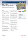
x600 Series Layer 3 Gigabit Ethernet Switches x600-24Ts x600-24Ts/XP x600-48Ts x600-48Ts/XP ◆ Installation Guide 613-001065 Rev. B Copyright © 2008 Allied Telesis, Inc. All rights reserved. No part of this publication may be reproduced without prior written permission from Allied Telesis, Inc. Allied Telesis and the Allied Telesis logo are trademarks of Allied Telesis, Incorporated. All other product names, company names, logos or other designations mentioned herein are trademarks or registered trademarks of their respective owners. Allied Telesis, Inc. reserves the right to make changes in specifications and other information contained in this document without prior written notice. The information provided herein is subject to change without notice. In no event shall Allied Telesis, Inc. be liable for any incidental, special, indirect, or consequential damages whatsoever, including but not limited to lost profits, arising out of or related to this manual or the information contained herein, even if Allied Telesis, Inc. has been advised of, known, or should have known, the possibility of such damages. Electrical Safety and Emissions Standards This product meets the following standards. U.S. Federal Communications Commission Radiated Energy Note: This equipment has been tested and found to comply with the limits for a Class A digital device pursuant to Part 15 of FCC Rules. These limits are designed to provide reasonable protection against harmful interference when the equipment is operated in a commercial environment. This equipment generates, uses, and can radiate radio frequency energy and, if not installed and used in accordance with this instruction manual, may cause harmful interference to radio communications. Operation of this equipment in a residential area is likely to cause harmful interference in which case the user will be required to correct the interference at his own expense. Note: Modifications or changes not expressly approved of by the manufacturer or the FCC, can void your right to operate this equipment. Industry Canada This Class A digital apparatus complies with Canadian ICES-003. Cet appareil numérique de la classe A est conforme à la norme NMB-003 du Canada. RFI Emissions FCC Class A, EN55022 Class A, EN61000-3-2, EN61000-3-3, VCCI Class A, C-TICK, CE Warning: In a domestic environment this product may cause radio interference in which case the user may be required to take adequate measures. EMC (Immunity) EN55024 Electrical Safety EN60950-1 (TUV), EN60825-1 (TUV), UL 60950-1 (CULUS), CSA-C22-2 No. 60950-1 (CULUS) Laser Safety EN60825 3 Translated Safety Statements Important: The indicates that a translation of the safety statement is available at www.alliedtelesis.com in a document entitled Translated Safety Statements (613-000990). 4 Contents Preface .............................................................................................................................................................. 7 Product Documentation ...................................................................................................................................... 8 Starting a Management Session ........................................................................................................................ 9 Safety Symbols Used in this Document ........................................................................................................... 10 Where to Find Web-based Guides ................................................................................................................... 11 Contacting Allied Telesis .................................................................................................................................. 12 Online Support ........................................................................................................................................... 12 Email and Telephone Support.................................................................................................................... 12 Warranty..................................................................................................................................................... 12 Returning Products .................................................................................................................................... 12 Sales or Corporate Information .................................................................................................................. 12 Management Software Updates................................................................................................................. 12 Chapter 1: Overview ...................................................................................................................................... 13 Introduction....................................................................................................................................................... 14 Switch Descriptions .......................................................................................................................................... 15 x600-24Ts Switch....................................................................................................................................... 15 x600-24Ts/XP Switch................................................................................................................................. 16 x600-48Ts Switch....................................................................................................................................... 17 x600-48Ts/XP Switch................................................................................................................................. 18 10/100/1000Base-T Twisted Pair Ports............................................................................................................ 19 Connector Type.......................................................................................................................................... 19 Speed......................................................................................................................................................... 19 Duplex Mode .............................................................................................................................................. 19 Maximum Distance..................................................................................................................................... 19 Cable Type................................................................................................................................................. 20 Auto-MDI/MDI-X......................................................................................................................................... 20 Port Pinouts................................................................................................................................................ 20 SFP Transceiver Slots...................................................................................................................................... 21 XFP Transceiver Slots...................................................................................................................................... 22 Redundant Twisted Pair Ports.......................................................................................................................... 23 SD Card Slot..................................................................................................................................................... 24 Port LEDs ......................................................................................................................................................... 25 10/100/1000Base-T Twisted Pair Port LEDs ............................................................................................. 25 SFP LEDs .................................................................................................................................................. 26 XFP Transceiver Slot LEDs ....................................................................................................................... 26 System LEDs.................................................................................................................................................... 27 Stack LEDs....................................................................................................................................................... 28 Secure Digital LEDs ......................................................................................................................................... 29 Terminal Port .................................................................................................................................................... 30 AT-RPS3204 Redundant Power Supply........................................................................................................... 31 AT-LBM Module................................................................................................................................................ 32 AC Power Connector........................................................................................................................................ 33 5 Contents Chapter 2: Installing the Hardware ............................................................................................................... 35 Reviewing Safety Precautions .......................................................................................................................... 36 Unpacking a Switch .......................................................................................................................................... 38 Installing the Power Cord Retaining Clip .......................................................................................................... 39 Installing the Switches in an Equipment Rack .................................................................................................. 40 Resetting the Switch ......................................................................................................................................... 42 Chapter 3: Cabling the Network Ports ......................................................................................................... 43 Twisted Pair and Fiber Optic Cable Specifications ........................................................................................... 44 Twisted Pair Cable Specifications .............................................................................................................. 44 Optional Transceiver Cable Specifications................................................................................................. 45 Installing Optional Transceivers ........................................................................................................................ 46 Installing an SFP Transceiver..................................................................................................................... 46 Installing an XFP Transceiver..................................................................................................................... 49 Cabling the Twisted Pair and Fiber Optic Ports ................................................................................................ 51 Powering on a Switch ....................................................................................................................................... 52 Starting a Local Management Session....................................................................................................... 53 Warranty Registration ....................................................................................................................................... 54 Chapter 4: Troubleshooting .......................................................................................................................... 55 Power LED is Off .............................................................................................................................................. 56 Twisted Pair Port Link LED is Off...................................................................................................................... 57 SFP or XFP LED is Off ..................................................................................................................................... 58 Transceiver is Installed but the Status is “Not Present” .................................................................................... 59 System Fault LED is Blinking ............................................................................................................................ 60 System Fault LED is Steadily On ...................................................................................................................... 61 Cannot Establish a Local (Out-of-Band) Management Session........................................................................ 62 Switch Functions Intermittently ......................................................................................................................... 63 Appendix A: Technical Specifications ......................................................................................................... 65 Physical Specifications ..................................................................................................................................... 65 Environmental Specifications ............................................................................................................................ 65 Power Specifications......................................................................................................................................... 66 Certifications ..................................................................................................................................................... 66 RJ-45 Twisted Pair Port Pinouts ....................................................................................................................... 67 RJ-45 Style Serial Terminal Port Pinouts.......................................................................................................... 69 RPS 21-pin D-combo Port and Connector Pinouts ........................................................................................... 70 6 Preface This guide contains the installation instructions for the x600 Series Layer 3 Gigabit Ethernet Switches. This preface contains the following sections: “Product Documentation” on page 8 “Starting a Management Session” on page 9 “Safety Symbols Used in this Document” on page 10 “Where to Find Web-based Guides” on page 11 “Contacting Allied Telesis” on page 12 7 Preface Product Documentation For overview information about the software features of the AlliedWare PlusTM Operating System Software which runs on the x600 Series Switches, refer to: 8 AlliedWare PlusTM Operating System Software Reference Guide x600 Layer 3 Gigabit Ethernet Switch Installation Guide Starting a Management Session For instructions that describe how to start a local management session on an x600 switch, refer to the “Starting a Local Management Session” on page 53. For information that describes how to log onto the AlliedPlusTM Operating System Software, see the AlliedWare PlusTM Operating System Software Reference Guide. 9 Preface Safety Symbols Used in this Document This document uses the safety symbols defined in Table 1. Table 1. Safety Symbols Symbol 10 Meaning Description Caution Performing or omitting a specific action may result in equipment damage or loss of data. Warning Performing or omitting a specific action may result in electrical shock. x600 Layer 3 Gigabit Ethernet Switch Installation Guide Where to Find Web-based Guides The installation and user guides for all Allied Telesis products are available in portable document format (PDF) on our web site at www.alliedtelesis.com. You can view the documents online or download them onto a local workstation or server. 11 Preface Contacting Allied Telesis This section provides Allied Telesis contact information for technical support as well as sales and corporate information. Online Support You can request technical support online by accessing the Allied Telesis Knowledge Base: www.alliedtelesis.com/support/kb.aspx. You can use the Knowledge Base to submit questions to our technical support staff and review answers to previously asked questions. Email and Telephone Support For Technical Support via email or telephone, refer to the Support section of the Allied Telesis web site: www.alliedtelesis.com. Warranty The x600 Series Layer 3 Gigabit Ethernet Switches are covered under a Lifetime Warranty (Two Years Fan & Power Supply). For warranty information, go to the Allied Telesis web site at www.alliedtelesis.com. Returning Products Products for return or repair must first be assigned a return materials authorization (RMA) number. A product sent to Allied Telesis without an RMA number will be returned to the sender at the sender’s expense. For instructions on how to obtain an RMA number, go to the Support section on our web site at www.alliedtelesis.com. Sales or Corporate Information You can contact Allied Telesis for sales or corporate information through our web site at www.alliedtelesis.com. Management Software Updates New releases of the management software for our managed products are available from the following Internet sites: Allied Telesis web site: www.alliedtelesis.com Allied Telesis FTP server: ftp://ftp.alliedtelesis.com If the FTP server prompts you to log on, enter “anonymous” as the user name and your email address as the password. 12 Chapter 1 Overview This chapter contains the following sections: “Introduction” on page 14 “Switch Descriptions” on page 15 “10/100/1000Base-T Twisted Pair Ports” on page 19 “SFP Transceiver Slots” on page 21 “XFP Transceiver Slots” on page 22 “Redundant Twisted Pair Ports” on page 23 “SD Card Slot” on page 24 “Port LEDs” on page 25 “System LEDs” on page 27 “Stack LEDs” on page 28 “Terminal Port” on page 30 “Secure Digital LEDs” on page 29 “AT-RPS3204 Redundant Power Supply” on page 31 “AT-LBM Module” on page 32 “AC Power Connector” on page 33 Note Do not begin the installation procedures in this guide until you have read the AlliedWare PlusTM Operating System Software Release Notes that are included with the latest release of the AlliedWare PlusTM Operating System Software. 13 Chapter 1: Overview Introduction The x600 Series Switches are managed Gigabit Ethernet switches that acts as standalone units. There are four Basic Layer 3 switches in the series: x600-24Ts Switch x600-24Ts/XP Switch x600-48Ts Switch x600-48Ts/XP Switch The x600-24Ts and the x600-24Ts/XP switches both have 24 10/100/1000Base-T ports. The x600-48Ts and the x600-48Ts/XP switches both have 44 10/100/1000 Base-T ports. All four switches have four SFP transceiver slots, an Secure Digital (SD) card slot, a console port, and a redundant power supply connector. In addition, the x600-24Ts/XP and the x600-48Ts/XP switches have two XFP transceiver slots. On the back of all the switches there is an AC power connector, an RPS connector, and an expansion slot. You can connect the RPS connector to the AT-RPS3204 Redundant Power Supply. The x600 switches are shipped with a blank expansion slot with the exception of the The x60048Ts/XP switch which is shipped with an AT-LBM (Link Back Mode) Module installed in the expansion slot. The AlliedWare PlusTM Operating System Software runs on all the x600 switches. For more detailed information about the switches, including illustrations, see “Switch Descriptions” on page 15. 14 x600 Series Layer 3 Gigabit Ethernet Switches Installation Guide Switch Descriptions The following sections describe the x600-24Ts, x600-24Ts/XP, x600-48Ts, x600-48Ts/XP Series Layer 3 Gigabit Ethernet Switches. x600-24Ts Switch The x600-24Ts switch has the following hardware features: 24 10/100/1000Base-T ports Four Gigabit Ethernet small form-factor pluggable (SFP) transceiver slots An RJ-45 style serial terminal port for local (out-of-band) management One SD slot supporting 512KB and 1GB SD cards Status LEDs for the ports, transceiver slots, and system Redundant power supply connector Expansion slot for the AT-StackXG Stacking Module Figure 1 shows the front panel of the x600-24Ts switch. Figure 2 shows the back panel of the x600-24Ts switch. System Port, SFP, and SD LEDs Slot LEDs 10/100/1000Base-T Ports 1 3 5 7 9 11 13 15 17 19 21R x600-24Ts 23R Layer 3 Gigabit Ethernet Switch PORT ACTIVITY L/A CLASS 1 LASER PRODUCT D/C 1000 LINK / FDX ACT 10/100 LINK / HDX / COL ACT SD READY BUSY STACK 1 3 5 7 9 11 13 15 17 SFP FAULT 2 L/A 21 FAULT L/A D/C 22 MASTER L/A L/A 23 RPS PRES D/C 24 PWR 2 2 4 6 8 10 12 14 16 18 20 22R 24R 21 22 23 STATUS MSTR SFP 1 CONSOLE L/A 19 21R 23R 4 6 8 10 12 14 16 18 RESET 20 22R 24R 24 1329 SFP Transceiver Slots RJ-45 Style Serial Terminal Port Figure 1. x600-24Ts Switch— Front Panel 100-240VAC~ RPS INPUT 1310 RPS Connector Expansion Slot AC Power Connector Figure 2. x600-24Ts Switch— Back Panel 15 Chapter 1: Overview x600-24Ts/XP Switch The x600-24Ts/XP switch has the following hardware features: 24 10/100/1000Base-T ports Four Gigabit Ethernet small form-factor pluggable (SFP) transceiver slots Two 10 Gigabit Ethernet small form factor pluggable (XFP) transceiver slots An RJ-45 style serial terminal port for local (out-of-band) management One SD slot supporting 512KB and 1GB SD cards Status LEDs for the ports, transceiver slots, and system Redundant power supply connector Expansion slot for the AT-StackXG Stacking Module Figure 3 shows the front panel of the x600-24Ts/XP switch. Figure 4 shows the back panel of the x600-24Ts/XP switch. Port, SFP, and SD Slot LEDs 10/100/1000Base-T Ports 1 3 5 7 9 11 13 15 17 19 21R x600-24Ts/XP 23R System LEDs Layer 3 Gigabit Ethernet Switch PORT ACTIVITY L/A CLASS 1 LASER PRODUCT D/C 1000 LINK / FDX ACT 10/100 LINK / HDX / COL ACT SD BUSY STACK SFP XFP L/A 1 1 6 8 10 12 14 16 18 20 22R 24R 21 22 23 24 25 5 7 9 11 13 15 17 CONSOLE STATUS L/A 19 21R 23R MSTR L/A 21 FAULT L/A D/C 22 MASTER 23 RPS 24 PWR L/A L/A PRES D/C 2 4 3 SFP FAULT XFP 2 2 READY 4 6 8 10 12 14 16 18 RESET 20 22R 24R 26 1307 SFP Slots XFP Slots RJ-45 Style Serial Terminal Port Figure 3. x600-24Ts/XP Switch— Front Panel 100-240VAC~ RPS INPUT 1310 RPS Connector Expansion Slot AC Power Connector Figure 4. x600-24Ts/XP Switch— Back Panel 16 x600 Series Layer 3 Gigabit Ethernet Switches Installation Guide x600-48Ts Switch The x600-48Ts switch has the following hardware features: 44 10/100/1000Base-T ports Four Gigabit Ethernet small form-factor pluggable (SFP) transceiver slots An RJ-45 style serial terminal port for local (out-of-band) management One SD slot supporting 512KB and 1GB SD cards Status LEDs for the ports, transceiver slots, and system Redundant power supply connector Expansion slot for the AT-StackXG Stacking Module Figure 5 shows the front panel of the x600-48Ts switch. Figure 6 shows the back panel of the x600-48Ts switch. RJ-45 Style Serial Terminal Port 10/100/1000Base-T Ports and LEDs SD Card Slot L/A L/A 1 3 5 7 9 11 13 15 17 19 1000 LINK / 21 ACT 10/100 LINK / 23 D/C ACT D/C 25 27 HDX / FDX 29 x600-48Ts COL 31 33 35 37 39 41 43 45 SFP Layer 3 Gigabit Ethernet Switch 47 SD READY BUSY FAULT CONSOLE STACK CLASS 1 LASER PRODUCT MSTR 1 L/A 2 L/A PRES 2 4 6 8 10 12 14 16 18 20 22 24 26 28 30 32 34 36 38 40 42 44 46 L/A STATUS FAULT MASTER RPS PWR RESET 48 1330 SFP Slots System LEDs Figure 5. x600-48Ts —Front Panel 100-240VAC~ RPS INPUT 1310 RPS Connector Expansion Slot AC Power Connector Figure 6. x600-48Ts —Back Panel 17 Chapter 1: Overview x600-48Ts/XP Switch The x600-48Ts/XP switch has the following hardware features: 44 10/100/1000Base-T ports Four Gigabit Ethernet small form-factor pluggable (SFP) transceiver slots Two 10 Gigabit Ethernet small form factor pluggable (XFP) transceiver slots An RJ-45 style serial terminal port for local (out-of-band) management One SD slot supporting 512KB and 1GB SD cards Status LEDs for the ports, transceiver slots, and system Redundant power supply connector AT-LBM module installed in the back of the switch Figure 7 shows the front panels of the x600-48Ts/XP switch. Figure 8 shows the back panel of the x600-48Ts/XP switch. RJ-45 Style Serial Terminal Port SD Card Slot 10/100/1000Base-T Ports and LEDs L/A L/A 1 3 5 7 9 11 13 15 17 19 1000 LINK / 21 ACT 10/100 LINK / 23 D/C ACT D/C 25 27 HDX / FDX 29 x600-48Ts/XP COL 31 33 35 37 39 41 43 45 SFP Layer 3 Gigabit Ethernet Switch 47 SD READY BUSY FAULT CONSOLE CLASS 1 LASER PRODUCT LINK / XFP SFP Slots 2 4 6 8 10 12 14 16 18 20 22 24 26 28 30 32 34 L/A ACT STACK XFP MSTR 1 L/A 2 L/A PRES 36 38 40 42 44 46 L/A 48 49 STATUS FAULT MASTER RPS PWR RESET 50 1308 XFP Slots SFP Slots System LEDs Figure 7. x600-48Ts/XP Switch —Front Panel 100-240VAC~ RPS INPUT AT-LBM 1309 AC Power Connector RPS Connector AT-LBM Module Figure 8. x600-48Ts/XP Switch —Back Panel 18 x600 Series Layer 3 Gigabit Ethernet Switches Installation Guide 10/100/1000Base-T Twisted Pair Ports This section describes the twisted pair ports on the switches. Connector Type Speed Duplex Mode The ports are 8-pin RJ-45 connectors that use four pins at 10 or 100 Mbps and all eight pins at 1000 Mbps. For the pin assignments, refer to “RJ-45 Twisted Pair Port Pinouts” on page 67. A port’s speed can be 10, 100, or 1000 Mbps. The speed can be set automatically through Auto-Negotiation, the default setting, or manually with the AlliedWare PlusTM Operating System Software. A twisted pair port can operate in either half- or full-duplex mode. (Fullduplex mode is the only mode available when a port is operating at 1000 Mbps.) The twisted pair ports are IEEE 802.3u-compliant and AutoNegotiate the duplex mode setting. You can disable Auto-Negotiation on one or all of the switch ports so that you can set the duplex mode manually through the AlliedWare PlusTM Operating System Software. Note In order for a switch port to successfully Auto-Negotiate its duplex mode with a 10 or 100 Mbps end node, the end node must be configured for Auto-Negotiation. Otherwise, a duplex mode mismatch can occur. A switch port using Auto-Negotiation defaults to half-duplex if it detects that the end node is not using AutoNegotiation. This results in a mismatch if the end node is operating at a fixed duplex mode of full-duplex. To avoid this problem when connecting an end node with a fixed duplex mode of full-duplex to a switch port, use the AlliedWare PlusTM Operating System Software to disable Auto-Negotiation on the port and set the port speed and duplex mode manually. Maximum Distance The ports have a maximum operating distance of 100 meters (328 feet). 19 Chapter 1: Overview Cable Type Auto-MDI/ MDI-X The cabling requirements for a 10/100/1000Base-T port are: For 10 Mbps operation: Standard TIA/EIA 568-B-compliant Category 3 or better shielded or unshielded cabling with 100 ohm impedance and a frequency of 16 MHz. For 100 Mbps operation: Standard TIA/EIA 568-A-compliant Category 5 or TIA/EIA 568-B-compliant Enhanced Category 5 (Cat 5e) shielded or unshielded cabling with 100 ohm impedance and a frequency of 100 MHz. For 1000 Mbps operation: Standard TIA/EIA 568-A-compliant Category 5 or TIA/EIA 568-B-compliant Enhanced Category 5 (Cat 5e) shielded or unshielded cabling with 100 ohm impedance and a frequency of 100 MHz. The twisted pair ports on the switch are IEEE 802ab-compliant and feature auto-MDI/MDI-X. This feature, available when a port’s speed and duplex mode are set through Auto-Negotiation, automatically configures a switch port to MDI or MDI-X depending on the wiring configuration of the port on the end node. This allows you to connect any network device to a port on the switch using a straight-through twisted pair cable. If Auto-Negotiation is disabled on a port and the speed and duplex mode are set manually, the auto-MDI/MDI-X feature is also disabled and the port’s wiring configuration defaults to the MDI-X setting. This setting can be configured with the AlliedWare PlusTM Operating System Software. Port Pinouts 20 Refer to Table 10 on page 67 for the port pinouts when a twisted pair port operates at 10 or 100 Mbps in the MDI configuration and Table 11 on page 67 for the MDI-X configuration. For port pinouts when a twisted pair port operates at 1000 Mbps, refer to Table 12 on page 68. x600 Series Layer 3 Gigabit Ethernet Switches Installation Guide SFP Transceiver Slots All of the x600 Series switches feature slots for four optional Gigabit Ethernet SFP transceivers that interconnect network devices over large distances using fiber optic cable. SFP tranceivers are also available with a copper cable interface allowing a host device designed primarily for optical fiber communications to also communicate over unshielded twisted pair networking cable. Figure 9 illustrates an SFP transceiver. Figure 9. SFP Transceiver Note For a list of supported SFP transceivers, contact your Allied Telesis sales representative. 21 Chapter 1: Overview XFP Transceiver Slots The x600-24Ts/XP and the x600-48Ts/XP Switches have two slots for optional XFP 10 Gigabit Ethernet transceivers to connect high speed, 10 gigabit devices to the switch or create high speed backbone networks between switches. Figure 10 shows an example of an XFP transceiver. 721 Figure 10. XFP Transceiver Note For a list of supported XFP transceivers, contact your Allied Telesis sales representative. 22 x600 Series Layer 3 Gigabit Ethernet Switches Installation Guide Redundant Twisted Pair Ports Four of the twisted pair ports on the x600-24-Ts and x600-24-Ts/XP switches are paired with SFP slots. The twisted pair ports are identified with the letter “R” for “Redundant” as part of their number on the faceplate of the unit. The ports and slots are listed in Table 2. Table 2. Twisted Pair Ports Matched with SFP Slots Models x600-24Ts and x600-24Ts/XP Ports and Slots 21R with SFP slot 21 22R with SFP slot 22 23R with SFP slot 23 24R with SFP slot 24 Follow these guidelines when using these ports and slots: Only one port in a pair can be active at a time. It can be either the twisted pair port or the corresponding SFP module. The twisted pair port is the active port when its SFP slot is empty, or when the SFP module is installed but has not established a link to the end node. The twisted pair port automatically changes to the redundant status mode when the SFP module establishes a link with the end node. The twisted pair port automatically transitions back to the active status when the link is lost on the SFP module. In nearly all cases, the twisted pair port and the SFP module share the same configuration settings, including port settings, VLAN assignments, access control lists, and Spanning Tree Protocol settings. An exception to the shared settings is port speed. If you disable AutoNegotiation on the twisted pair port and set the speed and duplex mode manually, the speed reverts to Auto-Negotiation when the SFP module establishes a link with the end node. 23 Chapter 1: Overview SD Card Slot All of the x600 Series Switches have an SD card slot which is designed for an SD card which stores configuration files and AlliedWare PlusTM Operating System Software image files. See Figure 11. x600-24Ts/X SD READY BUSY R FAULT 1 3 5 7 9 11 13 15 17 19 21R 23R 2 4 6 8 10 12 14 16 18 20 22R 24R L/A D/C L/A D/C 1318 Figure 11. SD Card Slot An SD card can make it easier for you to upgrade the files on a switch or transfer files between x600 switches. See Figure 12. LOCK SD Me mory Card 1319 Figure 12. SD Card Note An SD card is not required for normal operations of the switch. The x600 switches support various SD cards that are available from many vendors. To insert an SD card, position it so that the manufacturer’s brand label is facing up and press it into the slot until it is flush with the front of the chassis. The SD card is self-ejecting. To remove the SD card, press the card toward the x600 switch and the SD card pops out. For information on how to transfer files to and from a SD card, refer to the AlliedWare PlusTM Operating System Software Reference Guide. 24 x600 Series Layer 3 Gigabit Ethernet Switches Installation Guide Port LEDs The following sections describe the twisted pair port, SFP, and XFP LEDs. See Figure 13 for an illustration of the port LEDs on an x600-24Ts/XP. x600-24Ts/XP Layer 3 Gigabit Ethernet Switch PORT ACTIVITY K/ ACT 10/100 LINK / HDX / COL ACT SD BUSY STACK L/A READY 1 3 5 7 9 11 13 15 17 SFP FAULT CONSOLE STATUS L/A 19 21R 23R MSTR L/A 21 FAULT 1 L/A D/C 22 MASTER 2 L/A L/A 23 RPS PRES D/C 24 PWR XFP 2 4 6 8 10 12 14 16 18 RESET 20 22R 24R 26 1312 Figure 13. Port LEDs on an x600-24Ts/XP Switch 10/100/1000BaseT Twisted Pair Port LEDs A twisted pair port has two LEDs labeled L/A (link/activity) and D/C (duplex mode/collisions). The L/A LED indicates the speed and activity on a port. The D/C LED indicates the duplex mode (full- or half-duplex) and the status of collisions on the port. The twisted pair port LEDs appear on the right side of the x600-24Ts and x600-24Ts/XP faceplates. On the x600-48Ts and x600-48Ts/XP faceplates, the twisted pair port LEDs are interspersed among the twisted pair ports. Table 3 describes the LEDs for the 10/100/1000Base-T twisted pair ports. Table 3. Twisted Pair Port LEDs LED L/A Function Link Status and Activity State Description Off No link has been established between the port and the end node. Green The port has established a link at 1000 Mbps. Flashing green Packets are being received or transmitted at 1000 Mbps. Amber The port has established a link at 10 or 100 Mbps. Flashing amber Packets are being received or transmitted at 10 or 100 Mbps. 25 Chapter 1: Overview Table 3. Twisted Pair Port LEDs (Continued) LED D/C SFP LEDs Function Duplex Mode and Collisions State Description Green The port is operating in full-duplex mode. Amber The port is operating in half-duplex mode (only applies when operating at 10 or 100 Mbps). Flashing amber Collisions are occurring on the port (only applies when operating at 10 or 100 Mbps, half duplex mode). Each SFP transceiver slot on the x600 switches has one LED, defined in Table 4. Table 4. SFP Slot LED LED L/A XFP Transceiver Slot LEDs Function Link Status and Activity State Description Off No link has been established between the port and the end node. Green The port has established a link at 1 Gbps. Flashing green Packets are being received or transmitted at 1 Gbps. Each 10 Gigabit Ethernet transceiver slot on the x600-24Ts/XP and x60048Ts/XP switches has one LED, defined in Table 5. Table 5. XFP Slot LED LED L/A 26 Function Link Status and Activity State Description Off No link has been established between the port and the end node. Green The port has established a link at 10 Gbps. Flashing green Packets are being received or transmitted at 10 Gbps. x600 Series Layer 3 Gigabit Ethernet Switches Installation Guide System LEDs The system LEDs on the front panel display general status information. See Figure 14. x600-48Ts/XP Layer 3 Gigabit Ethernet Switch SD READY BUSY LINK / L/A FAULT CONSOLE ACT STACK XFP MSTR 1 2 L/A L/A PRES STATU S FAULT MASTER RPS PWR RESET 50 1313 Figure 14. System LEDs See Table 6 for a description of the system LEDs. Table 6. System LEDs LED FAULT MASTER RPS POWER State Description Off Indicates normal operation. Red Indicates a fault. The switch or the operating system software has malfunctioned. (Refer to Chapter 4, “Troubleshooting” on page 55 for instructions on how to troubleshoot a problem.) Off The switch is not a member of an enhanced stack or has an enhanced stacking status of slave or unavailable. Green The switch has an enhanced stacking status of master. Off No optional redundant power supply is connected to the switch. Green An optional redundant power supply is physically connected to the switch and may be powered on or off. Off The switch is not receiving power. Green The switch is receiving power. 27 Chapter 1: Overview Stack LEDs The STACK LEDs reflect the status of the two Stack ports on the AT-StackXG Stacking Module. These LEDs remain off if the module is not installed. See Table 7 for a description of the STACK LEDs. Table 7. STACK LEDs LED MSTR 1 L/A 2 L/A PRES 28 State Description Off The switch is not part of a stack or is a member unit of the stack. Green The switch is the master unit of the stack. Off Stack Port 1 has not established a link to a stacking port on another AT-StackXG Stacking Module. Green Stack Port 1 has established a link to a stacking port on another AT-StackXG Stacking Module. Flashing Green Stack Port 1 has established a link to a stacking port on another AT-StackXG Stacking Module and is sending or receiving packet traffic. Off Stack Port 2 has not established a link to a stacking port on another AT-StackXG Stacking Module. Green Stack Port 2 has established a link to a stacking port on another AT-StackXG Stacking Module. Flashing Green Stack Port 2 has established a link to a stacking port on another AT-StackXG Stacking Module and is sending or receiving packet traffic. Off The expansion slot for the AT-StackXG Stacking Module is empty. Green The AT-StackXG Stacking Module is installed in the switch. x600 Series Layer 3 Gigabit Ethernet Switches Installation Guide Secure Digital LEDs Both the x600-24Ts/XP and x600-48Ts/XP switches have one Secure Digital (SD) LED, defined in Table 8. Table 8. Secure Digital LED LED SD Function State Description Link Status and Activity Flashing amber Indicates a fault has been detected. The SD card is not valid or a read or write procedure was unsuccessful. Green An SD card has been detected. Flashing green An SD card is reading or writing data. Do not eject the SD card when it is in this state. 29 Chapter 1: Overview Terminal Port The terminal port is used to establish a local (out-of-band) management session with the switch. You establish a local management session by connecting a terminal or a personal computer with a terminal emulation program to the port. The terminal port has an RJ-45 style connector. An RJ-45 to RS-232 management cable is supplied with the switch. The terminal port is set to the following specifications: Default baud rate: 9600 bps (Range is 9600 to 115200 bps) Data bits: 8 Parity: None Stop bits: 1 Flow control: None Note These settings are for a DEC VT100 or ANSI terminal, or an equivalent terminal emulation program. 30 x600 Series Layer 3 Gigabit Ethernet Switches Installation Guide AT-RPS3204 Redundant Power Supply The RPS connector on the back panel of the switch connects to the optional AT-RPS3204 Redundant Power Supply Module, shown in Figure 15. The unit can provide power to the switch in the event that the switch’s internal power supply fails. The AT-RPS3204 Redundant Power Supply Module features one preinstalled AT-PWR3202 Power Supply and three empty slots for additional power supplies. Each power supply can support one x600 switch. When fully populated with AT-PWR3202 Power Supplies, the AT-RPS3204 unit can support up to four x600 switches simultaneously. The AT-RPS3204 Redundant Power Supply Module is hot swappable with the x600 switches. This means that it is safe to connect a powered on ATRPS3204 module to an x600 switch (which is also powered on) using a 21-pin D-combo connector cable from the module into the RPS connector on the x600 switch. For information about installing an AT-RPS3204 unit, consult the documentation shipped with the unit. POWE R AT-P WR3 204 Figure 15. AT-RPS3204 Redundant Power Supply Unit The pinouts for the redundant power supply’s 21-pin D-combo port and connector are described in “RPS 21-pin D-combo Port and Connector Pinouts” on page 70. 31 Chapter 1: Overview AT-LBM Module The AT-LBM (Link Back) Module is installed in the expansion slot of the x600-48Ts/XP switch. For an illustration, see Figure 8 on page 18. This module provides a nonblocking switching configuration when there are connections on the x600-48Ts/XP switch to all 44 copper ports and two XFP ports. 32 x600 Series Layer 3 Gigabit Ethernet Switches Installation Guide AC Power Connector The x600 switches have a single AC power supply socket on the back panel, which has autoswitch AC inputs. To power the switch on or off, connect or disconnect the power cord. Refer to “Technical Specifications” on page 65 for the input voltage range. 33 Chapter 1: Overview 34 Chapter 2 Installing the Hardware This chapter provides procedures to install an x600 switch. The chapter contains the following sections: “Reviewing Safety Precautions” on page 36 “Unpacking a Switch” on page 38 “Installing the Power Cord Retaining Clip” on page 39 “Installing the Switches in an Equipment Rack” on page 40 “Resetting the Switch” on page 42 35 Chapter 2: Installing the Hardware Reviewing Safety Precautions Please review the following safety precautions before you begin to install the switches or any of their components. Note The indicates that a translation of the safety statement is available in a PDF document titled “Translated Safety Statements” (613-000990) posted on the Allied Telesis website at www.alliedtelesis.com. Warning: Class 1 Laser product. L1 Warning: Do not stare into the laser beam. L2 Warning: To prevent electric shock, do not remove the cover. No user-serviceable parts inside. This unit contains hazardous voltages and should only be opened by a trained and qualified technician. To avoid the possibility of electric shock, disconnect electric power to the product before connecting or disconnecting the LAN cables. E1 Warning: Do not work on equipment or cables during periods of lightning activity. E2 Warning: Power cord is used as a disconnection device. To deenergize equipment, disconnect the power cord. E3 Warning: Class I Equipment. This equipment must be earthed. The power plug must be connected to a properly wired earth ground socket outlet. An improperly wired socket outlet could place hazardous voltages on accessible metal parts. E4 Pluggable Equipment. The socket outlet shall be installed near the equipment and shall be easily accessible. E5 Caution: Air vents must not be blocked and must have free access to the room ambient air for cooling. E6 Warning: Operating Temperature. This product is designed for a maximum ambient temperature of 40° degrees C. E7 36 x600 Layer 3 Gigabit Ethernet Switch Installation Guide All Countries: Install product in accordance with local and National Electrical Codes. E8 Circuit Overloading: Consideration should be given to the connection of the equipment to the supply circuit and the effect that overloading of circuits might have on overcurrent protection and supply wiring. Appropriate consideration of equipment nameplate ratings should be used when addressing this concern. E21 Caution: Risk of explosion if battery is replaced by an incorrect type. Replace only with the same or equivalent type recommended by the manufacturer. Dispose of used batteries according to the manufacturer’s instructions. Attention: Le remplacement de la batterie par une batterie de type incorrect peut provoquer un danger d’explosion. La remplacer uniquement par une batterie du même type ou de type équivalent recommandée par le constructeur. Les batteries doivent être éliminées conformément aux instructions du constructeur. E22 Warning: Mounting of the equipment in the rack should be such that a hazardous condition is not created due to uneven mechanical loading. E25 If installed in a closed or multi-unit rack assembly, the operating ambient temperature of the rack environment may be greater than the room ambient temperature. Therefore, consideration should be given to installing the equipment in an environment compatible with the manufacturer’s maximum rated ambient temperature (Tmra). E35 Caution: Installation of the equipment in a rack should be such that the amount of air flow required for safe operation of the equipment is not compromised. E36 Warning: Reliable earthing of rack-mounted equipment should be maintained. Particular attention should be given to supply connections other than direct connections to the branch circuits (e.g., use of power strips). E37 37 Chapter 2: Installing the Hardware Unpacking a Switch To unpack a switch, perform the following procedure: 1. Remove all components from the shipping packages. Note Store the packaging material in a safe location. You must use the original shipping material if you need to return the unit to Allied Telesis. 2. Place the switch on a level, secure surface. 3. Make sure the following components are included in your switch package. If any item is missing or damaged, contact your Allied Telesis sales representative for assistance. 38 One x600 Series Layer 3 Gigabit Ethernet Switch Two rack-mount brackets Eight flathead Phillips rack-mount bracket screws AC power cord (Americas, Australia, EU, Japan, and UK only) AC power cord retaining clip Management cable for local management x600 Layer 3 Gigabit Ethernet Switch Installation Guide Installing the Power Cord Retaining Clip Perform the following procedure to install the power cord retaining clip on the switches: 1. Locate the power cord retaining clip, shown in Figure 16. Figure 16. Power Cord Retaining Clip 2. Install the clip on the AC power connector on the back panel of the switch. With the “u” of the clip facing down, press the sides of the clip toward the center and insert the short ends into the holes in the retaining bracket, as shown in Figure 17. 100-2 40VA C~ 100-2 40VA C~ Figure 17. Inserting the Retaining Clip into the Retaining Bracket You are now ready to install the switches in the equipment rack, as explained in the next procedure. 39 Chapter 2: Installing the Hardware Installing the Switches in an Equipment Rack Perform the following procedure to install each switch in a standard 19-inch rack: Note Steps 1, 2, and 3 are optional. These steps provide instructions on how to remove the snap-on plastic feet from the bottom of a switch. You can leave the feet on. 1. Place the switch upside down on a level, secure surface. 2. Using a flat-head screwdriver, remove the snap-on plastic feet from the bottom of the switch, as shown in Figure 18. Figure 18. Removing the Feet 3. Turn the switch over. 4. Attach a rack-mount bracket to one side of the switch using four of the screws that come with the switch, as shown in Figure 19. 40 x600 Layer 3 Gigabit Ethernet Switch Installation Guide 15 17 19 21R 23R CLA LASER SS 1 PROD UCT 16 18 20 L/A SFP 22R D/C 24R 21 PORT 1000 ACTIV LINK / ITY FDX ACT 10/100 LINK / HDX / COL XF ACT P 22 L/A 23 STACK XFP 24 MSTR 1 25 L/A 2 L/A PRES 26 L/A x600 SD 1 3 5 7 9 D/C 11 13 L/A 15 17 D/C 2 4 6 READ Y BUSY -24Ts /XP FAU 19 21 LT R 23 R Layer 3 Gigabit Ethern et Sw SFP OLE STATU S 21 8 10 12 itch CONS L/A 22 14 16 18 FAUL T MAST ER RPS 23 20 22 R 24R 24 PWR RESE T 1327 Figure 19. Attaching Rack-Mount Brackets 5. Install the second rack-mount bracket on the other side of the switch with the four remaining screws. 6. Mount the switch in a 19-inch rack using standard screws (not provided), as shown in Figure 20. 1 3 5 7 9 11 13 15 17 19 2 21R 4 23R 6 8 10 12 14 CLAS S LASE R PRO1 DUCT 16 18 20 L/A SFP 22R D/C 24R 21 PORT 1000 ACTIVIT LINK / Y FDX ACT 10/100 LINK / HDX / COL ACT XFP 22 L/A 23 STACK XFP 24 MSTR 1 25 2 26 L/A L/A PRES L/A 1 x600 -24Ts/ XP SD 3 5 7 D/C 9 11 13 L/A READY 15 17 D/C 2 4 6 BUSY FAUL 19 21R T 23R 10 12 Layer 3 Gig abit Eth ernet Sw SFP L/A 21 8 CONSOL itch E STATUS 22 14 16 18 23 20 22R 24R 24 FAU LT MASTER RPS PWR RESET 1328 Figure 20. Mounting the Switch in a Rack 41 Chapter 2: Installing the Hardware Resetting the Switch You may need to reset the switch after upgrading the firmware or after you have made a configuration change that requires resetting the switch to activate the change. To reset the x600 switch, perform the following procedure: 1. Locate the RESET button which is on the right hand side of the faceplate. 2. Press the RESET button with the tip of a pen or a similar nonconducting object as shown in Figure 21. x600 -24Ts SD 9 11 13 15 17 READ Y BUSY FAUL 19 21 T R 23 R /XP L/A 21 10 12 Layer 3 Gig SFP CONS OL abit E thern et Sw itch E STATUS 22 14 16 18 20 22 R 24 R 23 FAU LT 24 MAST ER RPS PWR RESET 1321 Figure 21. Resetting the Switch 42 Chapter 3 Cabling the Network Ports This chapter contains the instructions for attaching network cables to an x600 switch. The chapter contains the following sections: “Twisted Pair and Fiber Optic Cable Specifications” on page 44 “Installing Optional Transceivers” on page 46 “Cabling the Twisted Pair and Fiber Optic Ports” on page 51 “Powering on a Switch” on page 52 “Warranty Registration” on page 54 43 Chapter 3: Cabling the Network Ports Twisted Pair and Fiber Optic Cable Specifications Twisted Pair Cable Specifications Table 9 lists the cabling specifications for the 10/100/1000Base-T twisted pair ports. Table 9. Twisted Pair Cabling and Distances Speed Cable Type Maximum Operating Distance 10 Mbps Standard TIA/EIA 568-B-compliant Category 3 or better shielded or unshielded cabling with 100 ohm impedance and a frequency of 16 MHz. 100 m (328 ft) 100 Mbps Standard TIA/EIA 568-A-compliant 100 m (328 ft) Category 5 or TIA/EIA 568-Bcompliant Enhanced Category 5 (Cat 5e) shielded or unshielded cabling with 100 ohm impedance and a frequency of 100 MHz. 1000 Mbps Standard TIA/EIA 568-A-compliant 100 m (328 ft) Category 5 or TIA/EIA 568-Bcompliant Enhanced Category 5 (Cat 5e) shielded or unshielded cabling with 100 ohm impedance and a frequency of 100 MHz. Note The auto-MDI/MDI-X feature on the twisted pair ports automatically configures the MDI/MDI-X setting when a link is established with an end node. Available when a port is at the default setting of AutoNegotiation, this feature allows you to use a straight-through twisted pair cable when connecting any type of network device to a port. Disabling Auto-Negotiation on a port and setting the speed and duplex mode manually also disables the auto-MDI/MDI-X feature. A port where Auto-Negotiation has been disabled defaults to MDI-X. Disabling Auto-Negotiation may require manually configuring a port’s MDI/MDI-X setting or using a crossover cable. 44 x600 Layer 3 Gigabit Ethernet Switch Installation Guide Optional Transceiver Cable Specifications The cable specifications for an optional SFP or XFP transceiver can be found in the transceiver’s installation guide that is shipped with the device. 45 Chapter 3: Cabling the Network Ports Installing Optional Transceivers Review the following guidelines before installing an optional SFP or XFP transceiver in a switch: A transceiver can be hot-swapped; the switch can be powered on when you install it. However, you should always disconnect the cables first before removing a transceiver. You must install the transceiver before you connect the cables to it. Fiber optic transceivers are dust sensitive. When a fiber optic cable is not installed, or when you store the transceiver, always keep the plug in the optical bores. When you do remove the plug, keep it for future use. Unnecessary removal and insertion of a transceiver can lead to premature failure. Warning A transceiver can be damaged by static electricity. Be sure to observe all standard electrostatic discharge (ESD) precautions, such as wearing an antistatic wrist strap, to avoid damaging the device. Installing an SFP Transceiver To install an SFP transceiver in an x600 switch, perform the following procedure: 1. Remove the dust plug from a transceiver slot on the switch, as shown in Figure 22. 23R CL LASE ASS 1 R PROD UCT L/A SFP D/C 24R 21 PORT 1000 AC LINK / FDX ACT XFP 22 L/A 23 24 25 1322 Figure 22. Removing a Dust Plug from an SFP Slot 2. Remove the transceiver from its shipping container and store the packaging material in a safe location. 46 x600 Layer 3 Gigabit Ethernet Switch Installation Guide 3. Position the transceiver with the label facing up. 4. Slide the transceiver into the slot until it clicks into place. 23R CL LASE ASS 1 R PROD UCT L/A SFP D/C 24R PORT 1000 AC LINK / FDX ACT 21 22 23 24 1331 Figure 23. Installing an SFP Transceiver 5. For the x600-24Ts and x600-24Ts/XP switches, verify that the handle on the SFP transceiver is in the upright position, as shown in Figure 24, to prevent inadvertently removing the transceiver. 23R CL LASE ASS 1 R PROD UCT L/A SFP D/C 24R PORT 1000 AC LINK / FDX ACT 21 22 23 24 1331 SFP Handle Figure 24. Positioning Handles on the x600-24Ts and x600-24Ts/XP Switches 47 Chapter 3: Cabling the Network Ports 6. For the x600-48Ts and x600-48Ts/XP switches, verify that handles on the top two SFPs are in the up position and the bottom two SFPs are in the down position as show in Figure 25. 41 43 45 SFP 47 x60 Laye 0-4 r3G ig SD CLA LASER SS 1 PROD UCT 42 44 XFP LINK / ACT L/A 46 L/A 48 49 1334 Figure 25. Positioning SFP Handles on the x600-48Ts and x600-48Ts/XP Switches 7. Repeat this procedure to install another SFP transceiver or go to “Cabling the Twisted Pair and Fiber Optic Ports” on page 51. For SFP optical and cabling specifications, consult the documentation shipped with the module. 48 x600 Layer 3 Gigabit Ethernet Switch Installation Guide Installing an XFP Transceiver To install an XFP transceiver in an x600 switch, perform the following procedure: 1. Remove the dust plug from a transceiver slot on the switch. Refer to Figure 26. L/A D/C PORT 1000 ACTI LINK VITY / FDX ACT 10/100 LINK / HDX / COL XF ACT P L/A STACK XFP 24 MSTR 1 25 2 L/A L/A PRES 26 L/A 1 SD 3 5 7 D/C 9 1 L/A D/C 2 4 6 8 10 1 1336 Figure 26. Removing an XFP Dust Plug 2. Remove the transceiver from its shipping container and store the packaging material in a safe location. 3. Position the transceiver with the label facing down. 4. Slide the transceiver into the slot until it clicks into place. L/A D/C PORT 1000 ACTI LINK VITY / FDX ACT 10/100 LINK / HDX / COL XF ACT P L/A STACK XFP 24 MSTR 1 25 2 26 L/A L/A PRES L/A 1 SD 3 5 7 D/C 9 1 L/A D/C 2 4 6 8 10 1 1316 Figure 27. Installing an XFP Transceiver 49 Chapter 3: Cabling the Network Ports 5. Repeat this procedure to install a second XFP transceiver or go to “Cabling the Twisted Pair and Fiber Optic Ports” on page 51. For XFP optical and cabling specifications, consult the documentation shipped with the module. 50 x600 Layer 3 Gigabit Ethernet Switch Installation Guide Cabling the Twisted Pair and Fiber Optic Ports Observe the following guidelines when connecting a twisted pair or fiber optic cable to a port on the switch: The connector on the cable should fit snugly into the port on the switch. The tab on the connector should lock the connector into place. Because the twisted pair ports on the switch are auto-MDI/MDI-X, any type of network device can be connected to a port on the switch using a straight-through twisted pair cable. If you disable Auto-Negotiation on the port, the port defaults to MDI-X. If your network topology contains a loop where two or more network devices can communicate with each other over more than one network path, do not connect the network cables forming the loop until you have activated a Spanning Tree Protocol on the switch. Data loops can adversely affect network performance. In order for a switch port to successfully Auto-Negotiate its duplex mode with an end node, the end node should also be using AutoNegotiation. Otherwise, a duplex mode mismatch can occur. A switch port using Auto-Negotiation defaults to half-duplex if it detects that the end node is not using Auto-Negotiation. This can result in a mismatch if the end node is operating at a fixed duplex mode of full-duplex. To avoid this problem, disable Auto-Negotiation on a switch port and set the port’s speed and duplex mode manually if the end node has a fixed duplex mode of full-duplex. 51 Chapter 3: Cabling the Network Ports Powering on a Switch To power on a switch, perform the following procedure: 1. Position the power cord retaining clip in the up position, as shown in Figure 28. 100-2 40VA C~ Figure 28. Power Cord Retaining Clip in the Up Position 2. Plug the power cord into the AC power connector on the back panel of the unit (see Figure 29). Warning: Power cord is used as a disconnection device. To deenergize equipment, disconnect the power cord. E3 100-2 40VA C~ Figure 29. Connecting the AC Power Cord 3. Connect the other end of the power cord to an appropriate AC power outlet. For power specifications for the switch, refer to “Power Specifications” on page 66. 52 x600 Layer 3 Gigabit Ethernet Switch Installation Guide 4. Start a local management session on the unit by performing the next procedure. Starting a Local Management Session The following procedure describes how to connect an RJ-45 cable to an x600 switch. For information about how to log onto the AlliedPlusTM Operating System Software, see the AlliedWare PlusTM Operating System Software Reference Guide. To start a local management session on the unit, perform the following procedure: 1. Connect the RJ-45 end of the management cable included with the x600 switch to the Terminal Port on the front panel of the switch, as shown in Figure 30. x600 -24Ts SD 9 11 13 15 17 READ Y BUSY /XP La yer 3 G igabit FAUL T 19 21 R 23 R SFP L/A 21 10 12 CONS OL Ether net S witch E STATUS 22 14 16 18 20 22 R 24 R 23 FAU LT 24 MAST ER RPS PWR RESET 1320 Figure 30. Connecting the Management Cable to the RJ-45 Terminal Port on the Switch 2. Connect the other end of the cable to an RS-232 port on a terminal or a personal computer with a terminal emulation program. 3. Configure the terminal or terminal emulation program as follows: Baud rate: Default is 9600 bps (Range is 9600 to 115200 bps) Data bits: 8 Parity: None Stop bits: 1 Flow control: None Note The port settings are for a DEC VT100 or ANSI terminal, or an equivalent terminal emulator program. 53 Chapter 3: Cabling the Network Ports Warranty Registration For warranty information, go to the Allied Telesis web site at www.alliedtelesis.com. 54 Chapter 4 Troubleshooting This chapter contains information about how to troubleshoot a switch in the event a problem occurs. Sections in the chapter include: “Power LED is Off” on page 56 “Twisted Pair Port Link LED is Off” on page 57 “SFP or XFP LED is Off” on page 58 “Transceiver is Installed but the Status is “Not Present”” on page 59 “System Fault LED is Blinking” on page 60 “System Fault LED is Steadily On” on page 61 “Cannot Establish a Local (Out-of-Band) Management Session” on page 62 “Switch Functions Intermittently” on page 63 Note If you are unable to resolve the problem after following the instructions in this chapter, contact Allied Telesis Technical Support for assistance. Refer to “Contacting Allied Telesis” on page 12 for contact information. 55 Chapter 4: Troubleshooting Power LED is Off Check the PWR LED on the front of the switch. If the LED is off, indicating that the unit is not receiving power, do the following: 56 Make sure the power cord is securely connected to the power source and to the AC connector on the back panel of the switch. Verify that the power outlet has power by connecting another device to it. Connect the unit to another power source. Use a different power cord. Check that the voltage from the power source is within the required levels for your region. x600 Layer 3 Gigabit Ethernet Switch Installation Guide Twisted Pair Port Link LED is Off When a twisted pair port on the switch is connected to a properly operating end node, the Link LED for the port should be on. If a Link LED is off, do the following: Note A 1000Base-T connection can take from five to ten seconds to establish a link. Verify that the end node connected to the port is powered ON and is operating properly. Check that the twisted pair cable is securely connected to the port on the switch and to the port on the end node. Make sure that the twisted pair cable does not exceed 100m (328 ft). Verify that you are using the appropriate category of twisted pair cable. For information, refer to Table 9 on page 44. Determine if a crossover cable is required. Since the twisted pair ports feature auto MDI/MDI-X, you should be able to use a straight-through cable regardless of the type of device you connect to a port. However, if you disable Auto-Negotiation on a port and set a port’s speed and duplex mode manually, the port defaults to MDI-X. Disabling AutoNegotiation may require manually configuring a port’s MDI/MDI-X setting or using a crossover cable. Make sure that the operating parameters of a port on the switch are compatible with the end node to which the port is connected. This may require using the switch’s operating system software. For a switch port to successfully Auto-Negotiate its duplex mode with an end node, the end node should also be using Auto-Negotiation. Otherwise, a duplex mode mismatch can occur. A switch port using Auto-Negotiation defaults to half-duplex if it detects that the end node is not using Auto-Negotiation. This can result in a mismatch if the end node is operating at a fixed duplex mode of full-duplex. To avoid this problem, disable Auto-Negotiation on a switch port and set the port’s speed and duplex mode manually if the end node has a fixed duplex mode of full-duplex. The switch has a bad cable detection feature that enables it to determine if a twisted pair cable has a electrical short that might cause a network loop. If the switch detects a bad cable on a port, it does not establish a link on that port. In this situation, replace the cable. 57 Chapter 4: Troubleshooting SFP or XFP LED is Off When a fiber optic port on the switch is connected to a properly operating end node, the Link LED for the port should be on. If a Link LED is off, do the following: Verify that the end node connected to the port is powered ON and is operating properly. Check that the fiber optic cable is securely connected to the port on the switch and the port on the end node. If the fiber optic port is on a SFP or XFP transceiver, check that the transceiver is firmly inserted into the slot on the switch. Make sure that you are using the appropriate type of fiber optic cable and that the cable length does not exceed the allowed maximum distance. For cable specifications for an SFP transceiver, refer to the installation instructions shipped with the module. Use a fiber optic tester to test the attenuation on the cable and the strength of the optical signal. For operating specifications for an SFP transceiver, refer to the installation instructions shipped with the module. Check that the operating specifications (for instance, wavelength and maximum operating distance) of the fiber optic port on the remote end node are compatible with the fiber optic port on the switch. Check that the fiber optic ports on the switch and on the end node are operating at the same speed and duplex mode. A fiber optic cable contains two separate fiber strands. One strand is for receiving data and the other is for transmitting data. When you connect a fiber optic cable to a port, be sure that the receive fiber connector is connected to the transmit connector on the remote end node. In addition, check that the transmit fiber connector is connected to the receive connector on the remote node. Note The L/A LED for an SFP transceiver slot may remain ON if you remove the transceiver when it has a link to an end node without first disconnecting the fiber optic cable. The L/A LED will change to OFF the next time an SFP module is installed in the slot. To avoid this, always disconnect the fiber optic cable before removing a transceiver. 58 x600 Layer 3 Gigabit Ethernet Switch Installation Guide Transceiver is Installed but the Status is “Not Present” If a SFP or XFP transceiver is installed in a transceiver slot but the Uplink Information menu in the AlliedWare PlusTM Operating System Software interface displays “Not Present” for that port, do the following: Verify that the transceiver is completely inserted in the slot on the front of the switch. Note The uplink status does not reflect whether a fiber optic cable is connected to the transceiver. 59 Chapter 4: Troubleshooting System Fault LED is Blinking A blinking FAULT LED indicates that the switch is updating the active boot configuration file.or a new version of the operating system software is in the process of being downloaded to the switch. The LED stops blinking after the switch has completed updating the boot configuration file or downloading the operating system software. 60 x600 Layer 3 Gigabit Ethernet Switch Installation Guide System Fault LED is Steadily On If the system FAULT LED is steadily on, a problem has occurred in the switch. Do the following: Reset the switch by disconnecting and reconnecting the AC power cord. If the FAULT LED remains ON, download a new version of the switch’s operating system software. For instructions, refer to the AlliedWare PlusTM Operating System Software Reference Guide. Note If the FAULT LED remains steadily on, contact Allied Telesis Technical Support for assistance. See “Contacting Allied Telesis” on page 12. 61 Chapter 4: Troubleshooting Cannot Establish a Local (Out-of-Band) Management Session If you are unable to establish a local (out-of-band) management session with the switch through the terminal port on the front panel, do the following: 62 Check that the RJ-45 serial management cable is securely connected to the serial terminal port on the switch and to the RS-232 port on the terminal or personal computer. Check that the operating parameters on the terminal or the terminal emulation program have been set correctly. The default settings for the RJ-45 serial terminal port can be found in “Starting a Local Management Session” on page 45. x600 Layer 3 Gigabit Ethernet Switch Installation Guide Switch Functions Intermittently If a switch functions intermittently, check the system hardware status through the management interface: Note the current voltage for the power supply compared to the optimum rating. Verify that the system temperature is within the operating range. 63 Chapter 4: Troubleshooting 64 Appendix A Technical Specifications Physical Specifications Dimensions (H x W x D): x600-24Ts x600-24Ts/XP x600-48Ts x600-48Ts/XP 44 mm x 440 mm x 305 mm (1.72 in. x 17.34 in. x 12.0 in.) 44 mm x 440 mm x 305 mm (1.72 in. x 17.34 in. x 12.0 in.) 44 mm x 440 mm x 305 mm (1.72 in. x 17.34 in. x 12.0 in.) 44 mm x 440 mm x 305 mm (1.72 in. x 17.34 in. x 12.0 in.) Weight: x600/24Ts x600-24Ts/XP x600-48Ts x600-48Ts/XP Recommended Minimum Ventilation on All Sides: 3.86 kg (8.50 lb.) 4.35 kg (9.60 lb.) 4.88 kg (10.75 lb.) 4.90 kg (10.80 lb.) 100 mm (4.0 in) Environmental Specifications Operating Temperature: 0° C to 40° C (32° F to 104° F) Storage Temperature: -25° C to 70° C (-13° F to 158° F) Operating Humidity: 5% to 90% noncondensing Storage Humidity: 5% to 95% noncondensing Maximum Operating Altitude: 3,048 m (10,000 ft) Maximum Nonoperating Altitude: 4,000 m (13,100 ft) 65 Appendix A: Technical Specifications Power Specifications Maximum Power Consumption: x600-24Ts x600-24Ts/XP x600-48Ts x600-48Ts/XP 76 watts 76 watts 123 watts 123 watts Input Voltage: AC 100-240V AC, 2.0 A maximum, 50/60 Hz Certifications EMI (Emissions): FCC Class A, ICES-003 Class A, EN55022 Class A, EN61000-3-2, EN61000-3-3, VCCI Class A, C-TICK, CE EMC (Immunity): EN55024 Electrical and Laser Safety: EN60950-1 (TUV), EN60825-1 (TUV), UL 60950-1 (CULUS), CSA-C22-2 No. 60950-1 (CULUS) Quality and Reliability (MTBF): x600-24Ts Compliance Marks: 66 130,000 hrs. x600-24Ts/XP 130,000 hrs. x600-48Ts 90,000 hrs. x600-48Ts/XP 90,000 hrs. CE, CULUS, TUV, C-Tick x600 Layer 3 Gigabit Ethernet Switch Installation Guide RJ-45 Twisted Pair Port Pinouts Figure 31 illustrates the pin layout of an RJ-45 connector and port. Pin 1 Figure 31. RJ-45 Connector and Port Pin Layout Table 10 lists the pin signals when a port is operating in the MDI configuration at 10 or 100 Mbps. Table 10. MDI Pin Signals - 10 or 100 Mbps Pin Signal 1 TX+ 2 TX- 3 RX+ 6 RX- Table 11 lists the pin signals when a port is operating in the MDI-X configuration at 10 or 100 Mbps. Table 11. MDI-X Pin Signals - 10 or 100 Mbps Pin Signal 1 RX+ 2 RX- 3 TX+ 6 TX- The MDI/MDI-X setting is established automatically when a port is set to Auto-Negotiation. If a port’s speed and duplex are set manually, the MDI/ MDI-X setting defaults to the MDI-X setting. 67 Appendix A: Technical Specifications Table 12 lists the pin signals when a port operating at 1000 Mbps. Table 12. Pin Signals - 1000 Mbps Pinout 68 Pair 1 Pair 1 + 2 Pair 1 - 3 Pair 2 + 4 Pair 3 + 5 Pair 3 - 6 Pair 2 - 7 Pair 4 + 8 Pair 4 - x600 Layer 3 Gigabit Ethernet Switch Installation Guide RJ-45 Style Serial Terminal Port Pinouts Table 13 lists the pin signals on the RJ-45 style serial terminal port. Table 13. RJ-45 Style Serial Terminal Port Pin Signals Pin Signal 4 Data Carrier Detect 3 Transmit Data 6 Receive Data 7 Data Set Ready 5 Ground 2 Data Terminal Ready 8 Clear to Send 1 Request to Send 69 Appendix A: Technical Specifications RPS 21-pin D-combo Port and Connector Pinouts Figure 32 illustrates the pin layout of the RPS 21-pin D-combo port and connector. 1 11 1 11 10 10 20 A1 A1 Figure 32. RPS 21-pin D-combo Connector and Port Pin Layout Table 14 lists the definitions for the RPS 21-pin D-combo port and connector pins. Table 14. RPS 21-pin Connector Pin Definitions Pin 70 Definition 1 Power supply ID 2 Fan 2 status 3 Fan 1 status 4 RPS status 5 Ground 6 Ground 7 RPS status 8 +12.0 VDC sense 9 Primary 12V 10 No connect 11 Ground 12 Ground 13 Ground 14 Ground 15 Ground 20 x600 Layer 3 Gigabit Ethernet Switch Installation Guide Table 14. RPS 21-pin Connector Pin Definitions (Continued) Pin Definition 16 Ground 17 Ground 18 +12.0 VDC sense 19 Ground 20 No connect A-1 +12.0 VDC 71 Appendix A: Technical Specifications 72