1
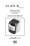
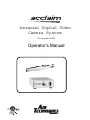
Intraoral Digital Video
Camera System
Part Number A5000
Operator’s Manual
TABLE OF CONTENTS
Page
Congratulations . . . . . . . . . . . . . . . . . . . . . . . . . . . . . . . . . . . . . . . . . . . . . . . . . . . . . . . . . . 3
Air Techniques Warranty . . . . . . . . . . . . . . . . . . . . . . . . . . . . . . . . . . . . . . . . . . . . . . . . . . 3
On-Line Warranty Registration . . . . . . . . . . . . . . . . . . . . . . . . . . . . . . . . . . . . . . . . . . . . . 3
Safety Notice . . . . . . . . . . . . . . . . . . . . . . . . . . . . . . . . . . . . . . . . . . . . . . . . . . . . . . . . . . . . 4
Box Contents . . . . . . . . . . . . . . . . . . . . . . . . . . . . . . . . . . . . . . . . . . . . . . . . . . . . . . . . . . . . 5
Unpacking and Inspection . . . . . . . . . . . . . . . . . . . . . . . . . . . . . . . . . . . . . . . . . . . . . . . . . 5
Key Parts Identification . . . . . . . . . . . . . . . . . . . . . . . . . . . . . . . . . . . . . . . . 6
Component Description . . . . . . . . . . . . . . . . . . . . . . . . . . . . . . . . . . . . . . . . . . . . . . . . . . . 6
Pre-Installation Information . . . . . . . . . . . . . . . . . . . . . . . . . . . . . . . . . . . . . . . . . . . . . . . . 7
Handpiece Keypad Button Functions . . . . . . . . . . . . . . . . . . . . . . . . . . . . . . . . . . . . . . . . 8
Control Module Controls and Connectors . . . . . . . . . . . . . . . . . . . . . . . . . . . . . . . . . . . . 9
S y s t e m I n t e r c o n n e c t i o n s . . . . . . . . . . . . . . . . . . . . . . . . . . . . . . . . . . . . . . . . . . . . . . . . . . . 10
Installation . . . . . . . . . . . . . . . . . . . . . . . . . . . . . . . . . . . . . . . . . . . . . . . . . . . . . . . . . . . . . .
Control Module Location . . . . . . . . . . . . . . . . . . . . . . . . . . . . . . . . . . . . . . . . . . . . . . . . . . .
Control Module Hanging Option . . . . . . . . . . . . . . . . . . . . . . . . . . . . . . . . . . . . . . . . . . . . .
Camera Handpiece Connection . . . . . . . . . . . . . . . . . . . . . . . . . . . . . . . . . . . . . . . . . . . . . .
Handpiece Holder Installation . . . . . . . . . . . . . . . . . . . . . . . . . . . . . . . . . . . . . . . . . . . . . . .
Control Module USB Video Connection Options . . . . . . . . . . . . . . . . . . . . . . . . . . . . . . . . . .
WDM Driver Installation . . . . . . . . . . . . . . . . . . . . . . . . . . . . . . . . . . . . . . . . . . . . . . . . . . . .
Video Connection Options . . . . . . . . . . . . . . . . . . . . . . . . . . . . . . . . . . . . . . . . . . . . . . . . . .
Operating Power Connection . . . . . . . . . . . . . . . . . . . . . . . . . . . . . . . . . . . . . . . . . . . . . . . .
PC Gameport Control Cable Installation . . . . . . . . . . . . . . . . . . . . . . . . . . . . . . . . . . . . . . . .
10
10
10
11
11
12
13
14
14
15
C a m e r a H a n d p i e c e P o r t a b i l i t y . . . . . . . . . . . . . . . . . . . . . . . . . . . . . . . . . . . . . . . . . . . . . . 16
I n f e c t i o n C o n t r o l S h e a t h . . . . . . . . . . . . . . . . . . . . . . . . . . . . . . . . . . . . . . . . . . . . . . . . . . 17
A c t i v a t i o n . . . . . . . . . . . . . . . . . . . . . . . . . . . . . . . . . . . . . . . . . . . . . . . . . . . . . . . . . . . . . . . 17
Final System Check . . . . . . . . . . . . . . . . . . . . . . . . . . . . . . . . . . . . . . . . . . . . . . . . . . . . . . .
Live Video Output Check . . . . . . . . . . . . . . . . . . . . . . . . . . . . . . . . . . . . . . . . . . . . . . . . . . .
USB Video Diagnostic . . . . . . . . . . . . . . . . . . . . . . . . . . . . . . . . . . . . . . . . . . . . . . . . . . . . .
PC Gameport Diagnostic . . . . . . . . . . . . . . . . . . . . . . . . . . . . . . . . . . . . . . . . . . . . . . . . . . .
18
18
18
19
C o m p u t e r - C o n n e c t e d S y s t e m O p e r a t i o n . . . . . . . . . . . . . . . . . . . . . . . . . . . . . . . . . . . . . 20
M o n i t o r - C o n n e c t e d S y s t e m O p e r a t i o n . . . . . . . . . . . . . . . . . . . . . . . . . . . . . . . . . . . . . . . 20
M a i n t e n a n c e . . . . . . . . . . . . . . . . . . . . . . . . . . . . . . . . . . . . . . . . . . . . . . . . . . . . . . . . . . . . . 21
S p e c i f i c a t i o n s . . . . . . . . . . . . . . . . . . . . . . . . . . . . . . . . . . . . . . . . . . . . . . . . . . . . . . . . . . . . 22
P h y s i c a l C h a r a c t e r i s t i c s . . . . . . . . . . . . . . . . . . . . . . . . . . . . . . . . . . . . . . . . . . . . . . . . . . . 22
A c c e s s o r i e s . . . . . . . . . . . . . . . . . . . . . . . . . . . . . . . . . . . . . . . . . . . . . . . . . . . . . . . . . . . . . . 23
2
CONGRATULATIONS
Congratulations on your purchase of the Acclaim Intraoral Digital Video Camera System, the latest
camera in the dental video imaging product line from Air Techniques, a leading manufacturer of dental
equipment since 1962.
The Acclaim Camera System design offers the benefits of a flexible and reliable image capturing
system that is easily integrated into any practice. The very lightweight one-piece toothbrush-size
Acclaim Camera Handpiece is an extremely maneuverable instrument, which produces crisp, clear
images.
In addition to providing quality high-resolution images, the Acclaim Camera Handpiece is a versatile addition that can grow with your practice. Using a quick-disconnect feature the Acclaim
Camera Handpiece quickly detaches and is easily carried among patient operatories for use with
other Acclaim Camera System components.
Start with a single counter-top Acclaim Camera System and, as your practice and your
requirements grow, add cameras, control modules, monitors, printer etc. Even integrate your
Acclaim Camera System with your existing computerized practice management software system.
This manual covers the installation, operation and maintenance of:
O
Acclaim Camera Handpiece with Control Module,
Power Supply Adapter and Cables . . . . . . . . . . . . . . . . . . . . . . . . . . . . . .Part Number A5000
O
Acclaim Camera Handpiece . . . . . . . . . . . . . . . . . . . . . . . . . . . . . . . . . .Part Number A5020
O
Control Module with Power Supply Adapter and Cables . . . . . . . . . . . . .Part Number A5050
Review and follow the guidelines included in this Operator’s Manual to ensure that your Acclaim
Camera System gives you the highest level of service.
For product support and information on how to expand your Acclaim Camera System, contact your
authorized Air Techniques dealer.
AIR TECHNIQUES WARRANTY
This Air Techniques equipment is warranted to be free from defects in material and workmanship from
the date of installation for a period of 2 years.
Any item returned to our factory in Hicksville, New York, through your authorized Air Techniques
dealer, will be repaired or replaced at our option at no charge provided that our inspection shall
indicate it to have been defective. Dealer labor, shipping and handling charges are not covered by
this warranty.
This warranty does not apply to damage due to shipping, misuse, careless handling or repairs by
other than authorized service personnel. Warranty void if installed or serviced by other than your
authorized Air Techniques dealer service personnel. Air Techniques, Inc. is not liable for indirect or
consequential damage or loss of any nature in connection with this equipment.
This warranty is in lieu of all other warranties expressed or implied. No representative or person is
authorized to assume for us any liability in connection with the sale of our equipment.
ON-LINE WARRANTY REGISTRATION
Quickly and easily register your new Acclaim Camera on-line. Just have your product model and serial
numbers available. Then go to the Air Techniques website, www.airtechniques.com, click the warranty
link and complete the registration form. This on-line registration ensures a record for the warranty
period and helps Air Techniques keep you informed of product updates and other valuable information.
3
SAFETY NOTICE
GENERAL
This equipment has been designed to minimize exposure of personnel to hazards. While the
Acclaim Camera System is designed for safe operation, certain precautions must be observed.
Use of the Acclaim Camera System not in conformance with the instructions specified in this
manual may result in permanent failure of the unit.
KNOWLEDGE OF WARNINGS AND CAUTIONS
Users must exercise every precaution to ensure personnel safety, and be familiar with the warnings
and cautions presented throughout this manual and summarized below.
CAUTION:
TO REDUCE THE RISK OF ELECTRICAL SHOCK, DO NOT REMOVE THE COVER OF THE CONTROL MODULE
OR POWER SUPPLY ADAPTER. THERE ARE NO USER-SERVICEABLE PARTS INSIDE. SERVICING SHOULD BE
PERFORMED BY QUALIFIED DEALER SERVICE REPRESENTATIVES ONLY.
CONNECTING ANY DEVICE TO THE ACCLAIM CAMERA SYSTEM THAT DOES NOT MEET THE EQUIVALENT
SAFETY REQUIREMENTS OF THE SYSTEM MAY REDUCE THE SAFETY EFFECTIVENESS OF THE ACCLAIM
CAMERA SYSTEM.
TURN
OFF POWER AND UNPLUG THE
CLEANING PROCEDURES.
WARNING:
ACCLAIM CAMERA SYSTEM
COMPONENTS BEFORE PERFORMING
TO PREVENT FIRE OR ELECTRICAL SHOCK, DO NOT EXPOSE THIS EQUIPMENT TO RAIN OR MOISTURE.
DO NOT SPRAY CLEANING LIQUIDS OR DISINFECTANTS DIRECTLY ON THE CAMERA HANDPIECE OR
CONTROL MODULE. USE CARE NOT TO ALLOW LIQUIDS TO RUN INTO INTERNAL CIRCUITRY.
DO NOT WIPE THE SURFACES USING BENZINE, THINNER, ETC. AS THIS MAY DEGRADE THE FINISH.
ATTENTION USERS:
MANUFACTURING DATE CODE ON SERIAL NUMBER LABEL IS IN THE FORMAT MONTH YYYY.
Alerts users to important Operating
and Maintenance instructions. Read
carefully to avoid any problems.
Indicates type BF equipment in
accordance with IEC 60601-1
Warns users that uninsulated voltage
within the unit may be of sufficient
magnitude to cause electric shock.
DO NOT ATTEMPT INTERNAL SERVICE
The interior of each component of the Acclaim system is only accessible by removing
hardware with tools and should only be opened and serviced by an authorized Air Techniques’
Dealer Service Technician. Please contact your local authorized Air Techniques dealer for service.
Failure to heed this warning may result in equipment damage and voiding the warranty.
4
BOX CONTENTS
Each component of the Acclaim Camera System is shipped packaged in individual protective
containers all packed in a single box, which includes:
Item
Supplied
Part No.
Camera Handpiece Assembly
1
A5020
Control Module without Capture
1
A5050
Power Supply Adapter
1
A5135
15-foot Multi-Conductor
Camera Handpiece Umbilical Cable Assembly
1
A5105
6-foot Composite Video Cable Assembly, RCA/RCA
1
77389
6-foot High Speed USB Cable Assembly, Type A/Type B
1
B3554
10-foot Game Port Control Cable Assembly,
8-pin Mini DIN/DB15 Male
1
A5115
Camera Handpiece Holder
1
A5145
Dual-Lock Fastener
1
A5155
20
See Page 23
Operator’s Manual
1
A5044
CD containing WDM video drivers for DirectX 9 compliant streaming video capture
software applications.
USB Video Diagnostic Software
PDF version of Operator’s Manual
1
A5151
Disposable Infection Control Sheaths
for Camera Handpiece
UNPACKING AND INSPECTION
Unpack each component of the Acclaim Camera System and inspect for physical damage such
as scratched panels, damaged connectors, etc. If any damage is noted, immediately notify your
Air Techniques authorized dealer immediately so corrective action can be taken.
Make sure to save all packaging material in case repackaging and shipment is necessary.
Verify that all listed items were received. If any item is missing, notify your Air Techniques
authorized dealer.
5
KEY PARTS IDENTIFICATION
CAMERA
HANDPIECE
P/N A5020
POWER SUPPLY
ADAPTER
USB 2.0 HIGH
SPEED VIDEO
CABLE
P/N B3554
P/N A5135
CAMERA HANDPIECE
Holder
with Double-Sided
Adhesive Fastener
P/N A5145
CAMERA HANDPIECE
CABLE
P/N A5105
COMPOSITE VIDEO CABLE
GAME PORT
CONTROL CABLE
P/N 77389
P/N A5115
CAMERA CONTROL
MODULE
WITH CABLES AND
POWER SUPPLY ADAPTER
P/N A5050
OPTIONAL
GAMEPORT TO USB
ADAPTER CABLE
P/N A5125
A5000 Acclaim Camera System Key Parts Identification
COMPONENT DESCRIPTION
The Acclaim Camera Systems is an intraoral camera system designed for dental applications that
consists of the Camera Handpiece with holder, Control Module, Power Supply Adapter and associated
cables as described below.
A5050 Control Module - The Control Module, part number A5050, is the single-point
interconnection interface for the system providing operating power, video and control connections
between the Camera Handpiece and various video outputs for connection to a computer and/or video
monitor as required. This Control Module is designed to connect to a PC with USB streaming video
capture software or to a PC with an installed capture card and associated video capture software.
When connected to a PC, the live video images taken by the Camera Handpiece are displayed on the
computer monitor and can be saved on the computer’s hard disk via the video capture software
application. When operated directly connected to only a video monitor, the connected monitor
displays high-resolution live video images taken by the Camera Handpiece.
Camera Handpiece - The Camera Handpiece, part number A5020, is extremely lightweight with a
high resolution, high sensitivity, auto-exposure controlled CCD sensor and a high performance lens
system illuminated by 7 ultra-bright white LED lamps. The fixed focus lens has a broad depth of field
bringing all objects measuring between 6 and 50 mm into focus enabling the camera to finely detail a
section of a single tooth to a full smile. The Camera Handpiece has 2 keypad buttons that provide fingertip operating control of the system. The specific functions performed by the keypad buttons depend
on system hardware and software installation configurations.
Power Supply Adapter - The 15-watt power supply adapter, part number A5135, connects to
the Control Module to provide 12 VDC power for operating the Acclaim Camera System.
6
COMPONENT DESCRIPTION
Camera Handpiece Holder with Double-Sided Adhesive Fastener - The Camera
Handpiece Holder, part number A5145, can be fastened in a convenient location for safe storage of
the Camera Handpiece when it is not in use. In addition to storage, the Camera Handpiece Holder
also has built-in magnets that turn off the Camera Handpiece power. This feature conserves energy
and equipment wear so the camera is ready and operational when needed.
Camera Handpiece Cable - This 15-foot multi-conductor cable with quick-disconnect connectors
at each end (part number A5105) interconnects between the Camera Handpiece and the Control
Module providing all power, video output and control for camera operation. Optional 6, 9, 30 and
50-foot length cables are available from your Air Techniques Dealer.
Gameport Control Cable - A 10-foot cable, part number A5115, that interconnects between the
Control Module and the gameport of the user’s PC. Allows the 2 keypad buttons on the camera to be
used instead of a gameport-connected footswitch to freeze/unfreeze and save images on a PC with a
user-supplied compatible streaming video capture software application. An optional 20-foot cable is
available from your Air Techniques Dealer.
Gameport to USB Adapter Cable - An optional external gameport to USB adapter cable, part
number A5125, is purchased separately to allow the PC Game Port Control cable to connect to the
USB Port of the user’s computer when no gameport is available.
USB 2.0 High Speed Cable - A 6-foot USB 2.0 cable, part number B3554 that connects between
the Control Module and the user’s computer. Provides a digital video output for use with a PC with
user-supplied compatible streaming video capture software application.
Composite Video Cable - A 6-foot composite video cable (part number 77389) is used to connect
between the Control Module and external video monitor or computer with video capture card for direct
viewing.
PRE-INSTALLATION INFORMATION
IMPORTANT::
When operating the Acclaim Camera System connected to the USB port on a
Computer System, the computer must be loaded with Air Techniques Authorized
DirectX 9 compliant streaming video software application.
Neither the Computer System nor the Software is provided by Air Techniques. The
Computer System and Software is provided by third party dealers.
Minimum Computer System Requirements - The Computer System (CPU, monitor, etc.) and
any related peripheral or other equipment, supplied by the user, or a third party, must comply with the
requirements for “Information Technology Equipment" (ITE) as specified in IEC 60950 (EN 60950).
Unless otherwise stated, the components of the computer system must comply with the minimum
requirements listed below.
CPU Speed:
Pentium-4, 2 GHz or higher
Operating System:
Windows 2000 Service Pack 4 or Windows XP Service Pack 1
with Microsoft knowledge base KB822603 update
DirectX 9 compliant streaming video software application installed
System RAM:
256 MB
CD ROM Drive:
24X or higher
Monitor :
SVGA 17" with 800 x 600 resolution or higher
Video Display Adapter:
16 MB video card with 800 x 600 pixel resolution and 32-bit color
USB Port:
Must be USB 2.0 high speed port
7
HANDPIECE KEYPAD BUTTON FUNCTIONS
Acclaim Camera
Handpiece
A5020
2
1
3
Keypad Buttons - Each keypad button provides the Acclaim Camera Handpiece fingertip control
over the PC streaming video capture software via the gameport cable. The specific functions performed
by the keypad buttons depend on system hardware and software installation configurations that support
a 2-button footswitch. Typical keypad actions provided below.
NOTE:
Simultaneously depressing both keypad buttons for approximately 3
seconds deactivates the Camera Handpiece LED light source. This is
commonly used when imaging an X-ray on a light box.
(1) Top Keypad Button
Sends a gameport footswitch button 1 command to the PC via the
gameport control cable. While the specific function performed
depends on the setting of the video capture software application
installed on the PC, this command typically freezes and unfreezes the
image that is displayed on the computer monitor.
(2) Bottom Keypad Button
Sends a gameport footswitch Button 2 command to the PC via the
gameport control cable. While the specific action depends on the
video capture software installed, it typically saves the image displayed
on the computer monitor to the computer hard disk.
(3) Handpiece Connector
An 8-pin connector socket that accepts connection of the keyed 8-pin
quick-disconnect plug end from the multi-conductor Handpiece cable.
Makes connection between the Camera Handpiece and Control Module
to provide power, video and control for the Acclaim Camera.
8
CONTROL MODULE CONTROLS AND CONNECTORS
POWER INDICATOR LAMP
Control Module
A5050
Front Panel
CAMERA Connector
A 10 pin connector socket that accepts connection of the keyed 10-pin
quick disconnect plug end from the multi-conductor Handpiece cable.
Makes connection between the Camera Handpiece and Control
Module to provide power, video output and control for the camera.
Power Indicator Lamp
A green LED lamp that illuminates to indicate the presence of 12 VDC
operating power from the power supply adapter.
STANDBY/ON Switch
A rocker panel switch that controls the application of 12 VDC operating
power from the Power Supply Adapter.
When set in the ON position, the 12 VDC is applied, the LED power
indicator lamp illuminates, and the camera is operational.
The 12 VDC is removed and the camera is turned off when the switch
is set in the STANDBY position and the LED power indicator lamp
extinguishes.
Control Module
A5050
Rear Panel
12 VDC Connector
Provides connection of the 12 VDC operating power from the Power
Supply Adapter.
S-VIDEO Connector
A 4-pin Mini DIN connector that provides output connection for
S -Video peripherals (e.g. video monitor or computer with capture
card).
VIDEO Connector
An RCA connector that provides connection for composite video
peripherals (e.g. video monitor or computer with capture card).
PC Connector
An 8-pin mini DIN connector that provides connection to the PC Game
Port of the computer.
USB Connector
A USB type B connector that provides connection to the USB 2.0 High
Speed port of the computer.
9
SYSTEM INTERCONNECTIONS
A5000 Acclaim System - The diagram below shows the possible interconnections of the A5000
Acclaim System using the A5050 Control Module (without internal capture card). The heavy solid
connection lines designate the typical operating configuration (connected to a computer system). The
dashed line shows the optional connection to a video monitor, while the lighter solid connection lines
show camera and power connections common to all system setups. Connect the A5000 System as
required by individual office equipment .
A5000 System Interconnection
USB 2.0
HIGH SPEED VIDEO
PC
COMPUTER
Typical Connections
Optional Connections
PC GAME PORT
CONTROL
Video
Capture Card
S-VIDEO OR
COMPOSITE
VIDEO
See Note
VIDEO
MONITOR
CAMERA
HANDPIECE
A5020
A5050
CONTROL
MODULE
BOTTOM
BUTTON
Note:
AC
INPUT
POWER
Required Connections
15-Foot
Multi-Conductor
Cable
POWER
SUPPLY
ADAPTER
12 VDC POWER
TOP
BUTTON
S-Video and Composite Video cables can
be connected to either a PC computer
with capture card or video monitor as
required by individual office equipment.
INSTALLATION
Installing the Acclaim Camera System is as simple as deciding where to place the Control Module
and making the necessary cable connections to a video monitor and/or a PC loaded with an Air
Techniques Authorized DirectX 9 compliant user-supplied streaming video software application.
Perform the following procedures to install the Acclaim Camera System.
Control Module Location - Locate the Acclaim Control Module on a table top, cart or any flat
stable surface convenient to an AC wall outlet and associated computer system/monitor. Make sure
that the selected location allows easy access to front and rear panel controls and connectors.
USE CARE WHEN ADHERING THE DUAL LOCK FASTENER TO SELECTED
SURFACE. THE ADHESIVE FASTENS QUICKLY AND PERMANENTLY.
Control Module Hanging Option - The Control Module can also be installed hanging under
a table top, under the chair or on the computer using the supplied Dual Lock Fastener Kit P/N
A5155. Refer to the instruction sheet provided with the Dual Lock Fastener Kit for procedures to
apply the fastener to the Control Module when using the hanging option.
10
INSTALLATION
DO
NOT TWIST OR TURN THE CABLE CONNECTORS.
EACH
CONNECTOR IS
KEYED AND MATES STRAIGHT ON WITH ASSOCIATED DEVICE CONNECTOR.
NOTE:
In addition to the supplied 15-foot multi-conductor cable, optional 6, 9, 30
and 50-foot lengths are available from your authorized Air Techniques Dealer
at an extra cost.
Camera Handpiece Connection - Carefully connect the supplied Camera Handpiece Cable
between the Camera Handpiece and Control Module as follows:
1. Using the gray molded connector cable end, align the connector key with the keyway of the
Handpiece connector.
2. Insert straight into Handpiece connector until it securely snaps into place.
3. Using the 10-pin quick disconnect plug end, align connector key with the keyway of the mating
CAMERA connector located on the front panel of the Control Module.
4. Insert the connector straight into the mating CAMERA connector until it securely snaps into
place.
Camera Handpiece Connection
HANDPIECE CABLE
10-PIN QUICK
CONNECTOR KEY
DISCONNECT PLUG
CAMERA HANDPIECE
A5050 Control Module/Camera Connection
USE CARE WHEN ADHERING THE HANDPIECE HOLDER TO SELECTED SURFACE.
THE DOUBLE-SIDED ADHESIVE FASTENS QUICKLY AND PERMANENTLY.
Handpiece Holder Installation - Remove the protective film from the double-sided adhesive
on the Handpiece Holder and attach the Holder to a flat, clean dry surface where the Camera
Handpiece will be located.
11
INSTALLATION
Control Module USB Video Connection Options - Refer to corresponding figure below and
perform the following procedure to connect the USB 2.0 High Speed Video output of the Acclaim
Control Module to the associated PC computer as desired.
1. Connecting Directly to PC. Connect the supplied 6-foot USB 2.0 high-speed cable between
the USB connector located on the rear of the Control Module to be connected and directly to
the USB 2.0 high speed port on the computer.
2. Connecting via High Speed Hub. Connect the supplied USB 2.0 high-speed cable between
the USB connector located on the rear of the Control Module to be connected and the selfpowered USB 2.0 High Speed Hub. If necessary connect an additional USB 2.0 high-speed
cable up to 16 feet long between the High Speed Hub and the USB 2.0 high speed port on
the computer.
3. With USB connection accomplished, refer to page 13 and install the WDM drivers from the
supplied CD onto the PC to enable the Acclaim Camera system to communicate with the
user-supplied USB streaming video software application running on the PC.
USB Cable Connection Directly to PC
REAR OF USER PC
NOTES:
REAR OF ACCLAIM
CONTROL MODULE
On PC's that have both front and rear USB 2.0
high speed ports, it is recommended that the
camera be connected to one of the rear
mounted ports for best results.
USB 2.0 HIGH
SPEED PORT
Minimum PC processor and operating system
requirements are listed in the Preinstallation
Information of this manual.
A DirectX 9 user-supplied compliant streaming
video capture software application must be
installed on the PC to display live video. The
supplied CD provides the required WDM drivers.
6-FOOT (2M ) USB 2.0 HIGH
SPEED CABLE (SUPPLIED)
USB Cable Connection via Hub
NOTES:
6-FOOT (2M ) USB 2.0 HIGH
POWER
SPEED CABLE (SUPPLIED)
A Hub may be used to connect the
SUPPLY
camera to the PC when the connection
ADAPTER
REAR OF ACCLAIM
is longer than 6 feet or when the PC
CONTROL MODULE
only has a single USB 2.0 high speed
port and the camera must be connected
along with other USB devices.
SELF-POWERED
USB 2.0
HIGH
SPEED
PORT
USB 2.0 HIGH
SPEED HUB
DO NOT use a USB BUS POWERED
HUB. Use only a self powered USB 2.0
high speed hub (ie: is powered from it's
own AC line powered supply).
UP TO 16-FOOT (5M) USB 2.0
HIGH SPEED CABLE
Follow instructions provided with the
hub to install it before connecting the
camera.
12
REAR OF USER PC
INSTALLATION
WDM Driver Installation - The supplied CD provides the WDM drivers needed to communicate
between the Acclaim Camera System and the associated user-supplied USB streaming video software
application installed on the PC computer system. Install the WDM drivers for the corresponding operating system (Windows 2000 or Windows XP) by performing the following procedures.
Installing Driver Files Under Windows 2000:
1. Insert the supplied CD into the CD-ROM drive on the PC. Windows may display a screen
providing options to install Acrobat Reader or to view the Acclaim Camera System
Operator's Manual. If so, click EXIT to close this screen.
2. Make sure that the supplied USB 2.0 high speed cable is connected per procedures above.
Windows should display the Found New Hardware Wizard Screen.
3. On the first wizard screen, click NEXT to continue.
4. On the second wizard screen, select the SEARCH FOR A SUITABLE DRIVER FOR MY
DEVICE option and then click NEXT to continue.
5. Select the CD-ROM DRIVES option and then click NEXT to continue.
6. Windows should now display a screen indicating that the wizard has found a driver for the
Acclaim Camera System in the DEVICE DRIVERS folder on the CD.
If so, click NEXT to continue.
If not, click BACK to return to the previous screen, select the SPECIFY A LOCATION option
in place of the CD-ROM DRIVES option, click NEXT and then use the BROWSE button to
manually locate the “Acclaim USB Camera.INF” file in the DEVICE DRIVERS folder on the
CD. Click NEXT to continue.
7. On the this wizard screen, Windows may indicate that a digital signature was not found.
Click YES to continue.
8. On the final wizard screen, click FINISH to complete the driver installation.
Installing Driver Files Under Windows XP:
1. Insert the supplied CD into the CD-ROM drive on the PC. Windows may display a screen
providing options to install Acrobat Reader or to view the Acclaim Camera System
Operator's Manual. If so, click EXIT to close this screen.
2. Make sure that the supplied USB 2.0 high speed cable is connected per procedures above.
Windows should display the Found New Hardware Wizard Screen.
3. Select the INSTALL THE SOFTWARE AUTOMATICALLY option and then click NEXT to
continue.
4. Windows may now display a screen indicating that the software for the Acclaim USB
Camera has not passed Windows logo testing. Click CONTINUE ANYWAY to continue.
5. On the next wizard screen, click FINISH to complete the driver installation.
13
INSTALLATION
Video Connection Options - Make connections as required by individual office equipment
to connect the Acclaim Camera System video outputs.
1. S-Video. Using an optional 6-foot S-Video, 4-Pin Mini DIN/4-pin Mini DIN cable
(PN 77379), connect between the S-VIDEO connector located on the rear of the A5050
Control Module and the associated connector of a video monitor or a computer with a
capture card as required.
2. Composite Video. Connect the supplied composite video cable between the VIDEO RCA
connector located on the rear of the A5050 Control Module and the associated RCA
connector of a video monitor or a computer with a capture card as required.
Optional Video Connections
REAR OF PC
Video
Monitor
Optional
S-Video
Cable to
Video
Monitor or
PC
Capture
Card
S-Video 4-Pin
Mini DIN
Connector
Composite
Video RCA
Connector
Acclaim Control
Module A5050
Rear Panel
Composite
Video RCA
Connector
S-Video
4-Pin Mini DIN
Connector
Video
Capture
Card
Composite Video Cable to
Video Monitor or PC
Capture Card
System Power Connection
Operating Power Connection - The A5050
Control Module receives operating power from the
supplied Power Supply Adapter (P/N A5135). Connect
the dc power cord of the Power Supply Adapter to the
12 VDC connector located on the rear of the Control
Module and then plug the Power Supply Adapter into
an AC wall outlet.
14
12 VDC
CONNECTOR
INSTALLATION
THE CAMERA HANDPIECE
KEYPAD BUTTON OPERATION CONTROL MAY BE USED IN PLACE
OF THE FOOTSWITCH THAT IS SUPPLIED WITH USER-SUPPLIED PC VIDEO CAPTURE SOFTWARE
APPLICATION SUPPORTING A GAMEPORT-CONNECTED FOOTSWITCH.
THIS
FEATURE MUST BE USED ON A PC WITH AN INTERNAL GAMEPORT OR WITH AN
OPTIONAL EXTERNAL A5125 GAMEPORT TO USB ADAPTER.
PC Gameport Control Cable Installation - Perform the following procedure as necessary to
connect the Acclaim Camera System using the supplied PC Game Port Control cable directly to a
PC with gameport or via an optional external A5125 gameport to USB adapter cable as follows:
1. Connection with gameport a. Connect the 8-Pin Mini DIN connector end of the PC Game Port Control cable to the PC connector located on the rear of the Control Module.
b. Connect the DB-15 connector end of the PC Game Port Control cable to the PC Game Port on
the PC. Tighten connector securing screws.
c. Perform step d. to typically install the required gameport driver on the PC running Windows
2000 or XP. If there is a problem with the gameport driver installation on Windows XP, perform
step e. as necessary.
d. Install the required gameport driver on the PC as follows:
1) Click Start from the Windows Desktop, select Settings and then click Control Panel.
2) Double click Gaming Options and select the Controllers tab.
3) Click the Add button, select the 2-Axis, 2-Button Joystick option from the list of game
controllers and then click OK.
4) Verify that the 2-Axis, 2-Button Joystick gameport controller/driver appears in the list of
installed game controllers. The status will be listed as OK when gameport cable is
connected.
e. If necessary install the required gameport driver on
computer systems running Windows XP as follows:
1) Click Start from the Windows XP Desktop, and select
Control Panel.
NOTE:
Make sure display is set for Classic View
Connection with Gameport
2) Double click the Game Controllers icon and select
the Add button on the Game Controllers window.
3) On the Add Game Controller window, select the
2-Axis, 2-Button Joystick option from the list of
game controllers and click the Custom button.
4) On the Custom Game Controller window, configure
the controller as follows:
a.) Select the Joystick radio button
b.) Select 2 from the Axes drop down box
c.) Select 2 from the Buttons drop down box
d.) Type in Acclaim into the Controller Name
field box
5) Verify configuration of Acclaim gameport controller
driver created above and click the OK button..
6) On the Add Game Controller window, select the
Acclaim controller from the list of game controllers
and click the OK button.
15
REAR OF PC
8-Pin Mini DIN
Connector
Audio/Game
PC Card
Supplied PC Game
Port Control Cable
INSTALLATION
2. Connection without gameport made via optional
external A5125 gameport to USB adapter cable a. Connect USB connector end of the A5125
adapter to the USB port on the rear of the PC.
b. Set the red DIP switch on DB-15 connector of the
A5125 USB adapter to the Joystick A
(option 2) position.
c. Turn on Computer and observe that the A5125
USB adapter is recognized.
d. Connect 8-Pin Mini DIN connector end of the PC
Game Port Control cable to the PC connector on
the rear of the Control Module.
e. Connect the DB-15 connector end of the PC
Game Port Control cable to the A5125
gameport to USB adapter DB-15 connector.
Tighten connector securing screws.
Connection without Gameport
REAR OF PC
USB
Port
8-Pin Mini DIN
Connector
Optional
USB
Adapter
Cable
Supplied PC Game
Port Control Cable
CAMERA HANDPIECE PORTABILITY
DO
NOT TWIST OR TURN THE
HANDPIECE CABLE CONNECTOR. THE CONNECTOR
CAMERA HANDPIECE CONNECTOR.
IS KEYED AND MATES STRAIGHT ON WITH
The Acclaim Camera Handpiece quickly detaches from the Handpiece Cable and is easily carried
among patient operatories for use with additional Acclaim Camera System Control Modules. Refer to
the corresponding illustrations and transport the Camera Handpiece as follows:
1. Retract collar of quick disconnect Handpiece Cable connector and simultaneously pull
straight from the Handpiece connector.
2. Release connector quick disconnect collar.
3. Store the Handpiece Cable by placing cable slide holder into the Handpiece Holder.
4. Transport Handpiece to next operatory.
5. Connect Handpiece at new location by aligning the connector key with the keyway
of the mating Handpiece Cable connector.
6. Insert straight into Handpiece connector until it securely snaps into place.
Detaching Camera Handpiece
Stored Handpiece Cable
Quick Disconnect
Connector End
Quick Disconnect Collar
Camera Handpiece
Handpiece Holder
Camera Handpiece Connection
Cable Slide Holder
Connector Key
Handpiece
Cable
Camera Handpiece
16
INFECTION CONTROL SHEATH
MAKE SURE TO USE A NEW DISPOSABLE INFECTION CONTROL
SHEATH (PN A5123) FOR EACH PATIENT.
NOTE:
For optimum image clarity, the optically clear section of the sheath
must be aligned with the camera lens by facing the camera/lightsource
section of the handpiece down toward the paper layer.
Disposable Sheath Installation - Install a new infection control sheath on the Camera
Handpiece for each patient as follows:
1. Remove the Camera Handpiece from the holder.
2. Insert the Camera Handpiece tip between the second
and third layers (between the outer paper and plastic
layers) with the camera/light facing towards the paper
layer. See A.
3. Push the Camera Handpiece completely in until the tip
is fully inserted into the narrow tip of the sheath. See B.
4. Gently squeeze the illuminated tip of the Camera
Handpiece between the thumb and index finger to
ensure that the optically clear area of the sheath is flat
against the lens tip. See C.
5. Peel away and discard the top plastic layer and the
bottom paper layer. See D.
ACTIVATION
NOTE:
Depending on the setup of the associated Acclaim Camera System,
power turn on for each system configuration varies.
When all components share a single power source, turn ON that
power source first.
When all components are plugged into a power strip with an ON/OFF
switch, place the power strip switch to the ON position. Verify that the
light on the ON/OFF switch illuminates.
When components are plugged into separate wall outlets, make sure
power is available at each outlet.
Power Turn On - Perform the following procedure as necessary to turn the power on for operation
of the Acclaim Camera System.
1. Review the Installation Section as necessary and make sure that the Acclaim Camera
System components are setup and connected for the applicable operating configuration.
2. If not connecting to a computer system, proceed to step 3. When connecting to a computer
system, turn on the computer and verify that the applicable video capture software and camera
drivers are installed.
3. On the connected video monitor, turn on the Power switch and verify operation.
4. On the associated Control Module front panel, set the STANDBY/ON switch to the ON
position and verify that the Control Module front panel LED indicator lamp lights.
5. Verify that the camera turns on and live video is displayed on the associated monitor when
the handpiece is removed from the Handpiece Holder.
6. Verify that the camera turns off when the handpiece is returned to the Handpiece Holder.
17
FINAL SYSTEM CHECK
Live Video Output Check - Upon activation, perform the steps below to check that live video is
correctly displayed on the connected monitor for the applicable operating configuration.
NOTE:
If there is no video or if the video is not correctly displayed when connected to
a computer system, contact your software provider to verify that the proper
Windows operating system service pack is installed and the video capture
software is configured for optimum performance.
Computer Connected Systems. When the Acclaim Camera System is connected to a computer system using a streaming video capture software application, perform the steps below to check
the live video output.
1. Start the installed streaming video capture software application.
2. Refer to the instructions provided with the installed video capture software application
and set the software to display NTSC (M) at a minimum resolution of 640 x 480 pixels
using the S-Video input video source on the Acclaim Camera video source.
3. Remove the Camera Handpiece from it's holder. The camera lamp should turn on.
4. Verify that live video from the camera is correctly displayed on the display monitor. If live
video is not displayed on the PC monitor when running the streaming video capture
software application, perform the USB Video Diagnostic procedure below.
Monitor Connected System. When the Acclaim Camera System is connected directly to only
a video monitor, check the live video output by observing that the monitor displays high-resolution live video images taken by the camera.
USB Video Diagnostic - When live video is not displayed on the PC monitor of the Acclaim
Camera System when the streaming video capture software application is running, there could be a
problem with the settings in the software application or with the camera system. Use the following USB
Video Diagnostic procedure to check that the camera and control module are working correctly, the
USB cable is correctly connected and the camera USB driver files are installed correctly on the PC.
1. Make sure that the associated Control Module is correctly connected to it's power supply, to
the Camera Handpiece and to the PC USB port and then turn on the power.
2. Insert the supplied USB driver CD disk into the CD-ROM drive.
3. Display the contents of this CD by double clicking the MY COMPUTER icon on the Windows
desktop. Right click the icon for your CD-ROM drive and select OPEN.
4. Open the Utilities folder on the CD and then double click the AMCAP.EXE icon to start the
software application.
5. On the AMCAP screen, click DEVICES on the menu bar along the top of the screen and make
sure that ACCLAIM USB CAMERA is selected from the drop down list.
6. Click OPTIONS on the menu bar along the top of the AMCAP screen and make sure that
PREVIEW is selected from the drop down list.
7. Depending on the outcome of the USB Video Diagnostic, perform one of the following:
a. If a live image is correctly displayed, exit from AMCAP application and make sure that the
streaming video capture software application is configured correctly.
b. If a live image is not displayed, exit from AMCAP application and check the camera, control module, USB cable and USB driver file installation.
c. If a live image is displayed but the image colors are not correct, reset the driver's video
settings by performing the procedures of step 8.
18
FINAL SYSTEM CHECK
8. Reset the driver's video settings by performing the following:
a. On the AMCAP screen, click OPTIONS on the menu bar along the top of the screen and
select VIDEO CAPTURE FILTER from the drop down list.
b. On the Properties screen select the VIDEO PROC AMP tab and then click the DEFAULT
button. The image colors should now be correct. Click OK to close the Properties screen
and exit from AMCAP application.
PC Gameport Diagnostic - If the buttons on the Camera Handpiece do not operate correctly
when the streaming video capture software application is running, there could be a problem with the
settings in the software application or with the camera system. Use the following PC Gameport
Diagnostic procedure to check that the Camera Handpiece and the Control Module are working
correctly and the gameport cable is correctly connected.
1. Make sure that the associated Control Module is connected to it's power supply, to the
Camera Handpiece and to the PC gameport (or the optional gameport-to-USB Adapter) and
then turn on the power.
2. Go to the Windows Control Panel, double click the GAMING OPTIONS icon. On the Gaming
Options screen select the CONTROLLERS tab.
3. Depending on the gameport cable connection, perform one of the following:
a. If the gameport cable is connected directly to the PC gameport, then observe that the
2-AXIS, 2-BUTTON JOYSTICK appears in the list of installed controller/drivers with it's status
listed as OK. If the status listed is not OK, check the gameport cable.
b. If the gameport cable is connected via the optional gameport-to-USB Adapter to the PC,
then observe that the USB ADAPTER appears in the list of installed controller/drivers with
it's status listed as OK. If the status listed is not OK, check the USB Adapter.
4. Check the operation of the Camera Handpiece buttons and the gameport cable connection
by clicking the PROPERTIES button from the Gaming Options screen. Select the TEST tab from
the Properties screen and verify the following:
a. Momentarily press the Top button on the Camera Handpiece and observe that the red
Button1 indicator on the screen illuminates briefly when the button is released.
b. Momentarily press the Bottom button on the Camera Handpiece and observe that the red
Button2 indicator on the screen illuminates briefly when the button is released.
c.
If the expected results for both buttons is verified, then the problem is most likely with the
streaming video capture software application. Make sure that the software application is
correctly installed and configured .
d. If the expected results for both buttons is not verified, then the problem is most likely a
hardware/ connection problem. Make sure that the Camera Handpiece, Control Module
and gameport cable are correctly installed.
19
SYSTEM OPERATION
Computer-Connected System Operation - The Acclaim Camera System A5000 is normally
operated connected directly to a computer system running various PC USB streaming video capture
software applications. In this configuration the camera provides the image/video source while the computer and associated software are used to display and save the resultant images. Perform the following
procedures to operate the Acclaim Camera System when connected to a computer.
Make sure that the Acclaim Camera System and
associated computer power is turned on.
Verify that the video capture software is running
and correctly configured.
1. Activate the Acclaim Camera System by performing the Power Turn-On procedures provided
on page 17.
2. Remove the Camera Handpiece from the handpiece holder and observe that the computer
display shows the high-resolution live video images taken by the camera.
3. Place the camera lens window over area of interest and view image on display.
4. Press the appropriate keypad button on the Camera Handpiece to freeze (ie. capture) the displayed image on the computer monitor screen. The keypad button used depends on the video
capture software installed.
5. Press the appropriate keypad button on the Camera Handpiece to save the captured image to
the computer hard drive and then to return to a live image display. The keypad button used
depends on the video capture software installed.
6. Repeat steps 3 through 5 as necessary.
7. When imaging an X-ray film on a light box, deactivate the LED light source by depressing both
Camera Handpiece buttons simultaneously for approximately 3 seconds. Perform steps 3
through 5 to freeze and save the X-ray film image as desired.
8. Return the Camera Handpiece to the holder when done. Verify that the LED light source and
camera turns OFF.
9. Set the STANDBY/ON switch on the Control Module front panel to the STANDBY position and
verify that the front panel LED indicator lamp extinguishes.
Monitor-Connected System Operation - The Acclaim Camera System can be operated directly
connected to a video monitor. In this configuration the connected monitor displays high-resolution live
video images taken by the camera. There is no computer system or software used to freeze and save
the resultant images. Perform the following procedures to operate the Acclaim Camera System when
connected to a video monitor.
1. Activate the Acclaim Camera System by performing the Power Turn-On procedures provided
on page 17.
2. Remove the Camera Handpiece from the Handpiece Holder and observe that the video monitor
display shows the high-resolution live video images taken by the camera.
3. Place the camera lens window over area of interest and view image on display.
4. When imaging an X-ray film on a light box, deactivate the LED light source by depressing both
Camera Handpiece buttons simultaneously for approximately 3 seconds.
5. Return the Camera Handpiece to the holder when done. Verify that the LED light source and
camera turns OFF.
6. Set the STANDBY/ON switch on the Control Module front panel to the STANDBY position and
verify that the front panel LED indicator lamp extinguishes.
20
MAINTENANCE
INSPECTION AND CLEANING
Perform the following inspection and cleaning procedures periodically as a preventive maintenance
measure to keep the Acclaim Camera System in optimal condition resulting in trouble-free operation
producing crisp, clear images.
DO NOT ATTEMPT ANY INTERNAL SERVICE OF ACCLAIM CAMERA SYSTEM COMPONENTS.
CONTACT YOUR LOCAL AUTHORIZED AIR TECHNIQUES DEALER FOR SERVICE. FAILURE TO
HEED THIS WARNING MAY RESULT IN EQUIPMENT DAMAGE AND VOIDING THE WARRANTY.
Inspection - Routinely inspect each component of the Acclaim Camera System for possible
defects as follows:
1. Camera Handpiece a. Check overall handpiece for chips, cracks or other irregularities.
b. Check the lens window for debris or spots.
c. Check the connector socket for damage.
2. Control Module a. Check for broken indicator lamp and switch.
b. Check all connector sockets for damage, loose or missing hardware.
3. Cables and Connectors a. Check cables for damaged or deteriorated insulation kinking or twisting.
b. Check connectors for loose, bent or missing pins.
c. Check that both quick-disconnect plug ends snap closed to snugly secure the Handpiece
Cable to the Camera Handpiece and Control Module connectors.
CAUTION: TURN OFF POWER AND UNPLUG THE ACCLAIM CAMERA SYSTEM COMPONENTS
BEFORE PERFORMING CLEANING PROCEDURES.
DO
NOT SPRAY CLEANING LIQUIDS OR DISINFECTANTS DIRECTLY
ON THE CAMERA HANDPIECE OR CONTROL MODULE. USE CARE
NOT TO ALLOW LIQUIDS TO RUN INTO INTERNAL CIRCUITRY.
DO NOT WIPE THE SURFACES USING BENZINE, THINNER, ETC. AS
THIS MAY DEGRADE THE FINISH.
Cleaning - Clean each component of the Acclaim Camera System as necessary by performing the
following procedures.
1. Control Module - Use a non-corrosive surface disinfectant such as Birex® se.
2. Camera Handpiece - Following every patient use, the Camera Handpiece can be wiped
clean and disinfected with any non-corrosive surface disinfectant such as Birex® se.
3. Camera Window Lens - Remove debris or spots from lens window by cleaning with alcohol
and cotton swabs.
21
SPECIFICATIONS
External Adapter Voltage input:
100-240 Volts ±10%
Frequency:
50/60 Hz
Voltage Output:
12 VDC
(Optional adapter configurations available for international outlet usage.)
Power Consumption:
Video Outputs:
Sensor:
Format:
Pixels:
Resolution:
Signal to Noise Ratio:
Exposure Control:
Illumination:
Image:
Viewing Angle:
Operating Temperature:
Storage Temperature:
Humidity:
Classifications:
Protection for Ingress
of Water:
Flammable Atmosphere:
4.8 watts
S-Video, Composite Video, High Speed USB 2.0 Video
¼ Inch CCD
NTSC
768 H X 494 V
470 TV lines
> 50 dB
Automatic
7 Ultra-bright white LED lamps
Normal, not mirrored
50 Degrees horizontal
10º to 40º C
0º to 70º C
10 to 90% non-condensing
Portable, Continuous Operation, Class 2, Type BF
Ordinary
Cannot use in the vicinity of flammable anesthetic
mixtures of air, oxygen or nitrous oxide.
Minimum PC Requirements for USB Video Feature:
CPU Speed:
Pentium-4, 2 GHz or higher
Operating System:
Windows 2000 Service Pack 4 or Windows XP Service Pack 1 with
Microsoft knowledge base KB822603 update
DirectX 9 compliant streaming video software application installed
System RAM:
256 MB
CD ROM Drive:
24X or higher
Monitor :
SVGA 17" with 800 x 600 resolution or higher
Video Display Adapter:
16 MB video card with 800 x 600 pixel resolution and 32-bit color
USB Port:
Must be USB 2.0 high speed port
PHYSICAL CHARACTERISTICS
Dimensions
Length
Width
Height
Weight
Handpiece A5020:
8.3 inches
(211 mm)
1.0 inches
(25 mm)
0.9 inches
(23 mm)
2.1 oz.
Control Module:
without Capture A5050:
6.4 inches
(163 mm)
3.7 inches
(94 mm)
1.5 inches
(38 mm)
0.7 lbs.
22
ACCESSORIES
The following lists the ordering number and description for accessory components available to
maintain and expand the Acclaim Camera System to meet your professional needs. Contact your
Air Techniques Dealer for information.
Acclaim Camera System
Order
Number
Description
A5000
Complete Acclaim Camera System consisting of the following:
A5020
Acclaim Camera Handpiece Assembly
A5050
Acclaim Control Module consisting of the following:
Acclaim Control Module Assembly
Wall-Mounted Power Supply Adapter, P/N A5135
15-foot Multi-Conductor Camera Handpiece Cable Assembly, P/N A5105
6-foot Composite Video Cable, RCA/RCA, P/N 77389
6-foot USB 2.0 High Speed Cable, Type A/Type B, P/N B3554
10-foot Game Port Control Cable, 8-pin Mini DIN/DB-15 Male, P/N A5115
Camera Handpiece Holder with Double-Sided Adhesive Fastener, P/N A5145
Dual Lock Fastener Kit for Control Module Mounting, P/N A5155
Disposable Infection Control Sheaths for Camera Handpiece (Quantity 20)
A5151
CD containing WDM video drivers for DirectX 9 compliant
streaming video capture software applications.
USB Video Diagnostic Software
PDF version of Operator’s Manual
A5044
Operator's Manual
A5110
A5100
Replacement Disposable Infection Control Sheaths for Camera Handpiece
Box of 100
Box of 500
A5105-6
A5105-9
A5105-30
A5165
Optional Multi-Conductor Camera Handpiece Cable Assemblies
6-Foot Length Cable Assembly
9-Foot Length Cable Assembly
30-Foot Length Cable Assembly
50-Foot Length Cable Assembly
A5115-20
Optional 20-Foot Length Gameport Cable
A5125
Optional External Gameport to USB Adapter Cable
77379
Optional 6-foot S-Video, 4-Pin Mini DIN/4-pin Mini DIN Cable
77389
Optional 6-foot Composite Video Cable, RCA/RCA
23
Air Techniques is a leading manufacturer of fine dental equipment from
air and vacuum systems and X-ray film processors, to an impressive line
of new products incorporating the most recent technological advances.
These new products, vital components of the innovative dental practice,
include intraoral cameras, air abrasion systems, rapid curing and bleaching systems, a digital imaging system which utilizes phosphor plate technology and, most recently, an intraoral X-ray system.
Air Techniques has been manufacturing quality products for the dental
professional since 1962.
K
Acclaim Intraoral Digital Video Camera System
K
AirDentJ II / AirDent II CSJ
K
AirStar®
K
GuardianJ Amalgam Collector
K
A/T 2000® XR
K
ARC Light®
K
Peri-Pro®
K
Provecta 70J
K
ScanXJ
K
SLC
K
STSJ
K
VacStarJ
K
VistaCam Omni®
K
VistaCam Omni® ic4
CORPORATE HEADQUARTERS
70 Cantiague Rock Road, P. O. Box 870, Hicksville, New York 11802-0870
1-800-AIR-TECH
(516) 433-7676
FAX: (516) 433-7684
(1-800-247-8324)
©Air Techniques, Inc. 2004
PN A5044 Rev. G
WESTERN FACILITY
291 Bonnie Lane, Suite 101, Corona, CA 92880
1-800-822-2899
(951) 898-8555
FAX: (951) 898-7646
www.airtechniques.com