1
Sun Blade™ X6270 Server Module
Service Manual
Part No. 820-6178-13, Rev. A
September 2010
Copyright © 2010, Oracle and/or its affiliates. All rights reserved.
This software and related documentation are provided under a license agreement containing restrictions on use and disclosure and are protected by
intellectual property laws. Except as expressly permitted in your license agreement or allowed by law, you may not use, copy, reproduce, translate,
broadcast, modify, license, transmit, distribute, exhibit, perform, publish, or display any part, in any form, or by any means. Reverse engineering,
disassembly, or decompilation of this software, unless required by law for interoperability, is prohibited.
The information contained herein is subject to change without notice and is not warranted to be error-free. If you find any errors, please report them to us
in writing.
If this is software or related software documentation that is delivered to the U.S. Government or anyone licensing it on behalf of the U.S. Government, the
following notice is applicable:
U.S. GOVERNMENT RIGHTS. Programs, software, databases, and related documentation and technical data delivered to U.S. Government customers
are "commercial computer software" or "commercial technical data" pursuant to the applicable Federal Acquisition Regulation and agency-specific
supplemental regulations. As such, the use, duplication, disclosure, modification, and adaptation shall be subject to the restrictions and license terms set
forth in the applicable Government contract, and, to the extent applicable by the terms of the Government contract, the additional rights set forth in FAR
52.227-19, Commercial Computer Software License (December 2007). Oracle America, Inc., 500 Oracle Parkway, Redwood City, CA 94065.
This software or hardware is developed for general use in a variety of information management applications. It is not developed or intended for use in any
inherently dangerous applications, including applications which may create a risk of personal injury. If you use this software or hardware in dangerous
applications, then you shall be responsible to take all appropriate fail-safe, backup, redundancy, and other measures to ensure its safe use. Oracle
Corporation and its affiliates disclaim any liability for any damages caused by use of this software or hardware in dangerous applications.
Oracle and Java are registered trademarks of Oracle and/or its affiliates. Other names may be trademarks of their respective owners.
AMD, Opteron, the AMD logo, and the AMD Opteron logo are trademarks or registered trademarks of Advanced Micro Devices. Intel and Intel Xeon are
trademarks or registered trademarks of Intel Corporation. All SPARC trademarks are used under license and are trademarks or registered trademarks of
SPARC International, Inc. UNIX is a registered trademark licensed through X/Open Company, Ltd.
This software or hardware and documentation may provide access to or information on content, products, and services from third parties. Oracle
Corporation and its affiliates are not responsible for and expressly disclaim all warranties of any kind with respect to third-party content, products, and
services. Oracle Corporation and its affiliates will not be responsible for any loss, costs, or damages incurred due to your access to or use of third-party
content, products, or services.
Copyright © 2010, Oracle et/ou ses affiliés. Tous droits réservés.
Ce logiciel et la documentation qui l’accompagne sont protégés par les lois sur la propriété intellectuelle. Ils sont concédés sous licence et soumis à des
restrictions d’utilisation et de divulgation. Sauf disposition de votre contrat de licence ou de la loi, vous ne pouvez pas copier, reproduire, traduire,
diffuser, modifier, breveter, transmettre, distribuer, exposer, exécuter, publier ou afficher le logiciel, même partiellement, sous quelque forme et par
quelque procédé que ce soit. Par ailleurs, il est interdit de procéder à toute ingénierie inverse du logiciel, de le désassembler ou de le décompiler, excepté à
des fins d’interopérabilité avec des logiciels tiers ou tel que prescrit par la loi.
Les informations fournies dans ce document sont susceptibles de modification sans préavis. Par ailleurs, Oracle Corporation ne garantit pas qu’elles
soient exemptes d’erreurs et vous invite, le cas échéant, à lui en faire part par écrit.
Si ce logiciel, ou la documentation qui l’accompagne, est concédé sous licence au Gouvernement des Etats-Unis, ou à toute entité qui délivre la licence de
ce logiciel ou l’utilise pour le compte du Gouvernement des Etats-Unis, la notice suivante s’applique :
U.S. GOVERNMENT RIGHTS. Programs, software, databases, and related documentation and technical data delivered to U.S. Government
customers are "commercial computer software" or "commercial technical data" pursuant to the applicable Federal Acquisition Regulation and
agency-specific supplemental regulations. As such, the use, duplication, disclosure, modification, and adaptation shall be subject to the
restrictions and license terms set forth in the applicable Government contract, and, to the extent applicable by the terms of the Government
contract, the additional rights set forth in FAR 52.227-19, Commercial Computer Software License (December 2007). Oracle America, Inc., 500
Oracle Parkway, Redwood City, CA 94065.
Ce logiciel ou matériel a été développé pour un usage général dans le cadre d’applications de gestion des informations. Ce logiciel ou matériel n’est pas
conçu ni n’est destiné à être utilisé dans des applications à risque, notamment dans des applications pouvant causer des dommages corporels. Si vous
utilisez ce logiciel ou matériel dans le cadre d’applications dangereuses, il est de votre responsabilité de prendre toutes les mesures de secours, de
sauvegarde, de redondance et autres mesures nécessaires à son utilisation dans des conditions optimales de sécurité. Oracle Corporation et ses affiliés
déclinent toute responsabilité quant aux dommages causés par l’utilisation de ce logiciel ou matériel pour ce type d’applications.
Oracle et Java sont des marques déposées d’Oracle Corporation et/ou de ses affiliés.Tout autre nom mentionné peut correspondre à des marques
appartenant à d’autres propriétaires qu’Oracle.
AMD, Opteron, le logo AMD et le logo AMD Opteron sont des marques ou des marques déposées d’Advanced Micro Devices. Intel et Intel Xeon sont des
marques ou des marques déposées d’Intel Corporation. Toutes les marques SPARC sont utilisées sous licence et sont des marques ou des marques
déposées de SPARC International, Inc. UNIX est une marque déposée concédée sous licence par X/Open Company, Ltd.
Ce logiciel ou matériel et la documentation qui l’accompagne peuvent fournir des informations ou des liens donnant accès à des contenus, des produits et
des services émanant de tiers. Oracle Corporation et ses affiliés déclinent toute responsabilité ou garantie expresse quant aux contenus, produits ou
services émanant de tiers. En aucun cas, Oracle Corporation et ses affiliés ne sauraient être tenus pour responsables des pertes subies, des coûts
occasionnés ou des dommages causés par l’accès à des contenus, produits ou services tiers, ou à leur utilisation.
Please
Recycle
Contents
Preface
1.
2.
ix
Sun Blade X6270 Hardware and Software Features
1.1
Server Hardware and Software Features
1.2
Server Indicators and Buttons
1.3
Attaching Devices To the Server
1–5
1.4
Replaceable Server Components
1–7
Powering On and Off the Server
2–1
2–2
2.1.1
Power On the Server Module
2.1.2
Power Off and Verify Server Is Ready for Removal From Chassis
2–3
2.1.3
Troubleshoot Server Power States
2.1.4
Wake On LAN – Remote Power On
2.1.4.1
2.2
1–2
1–4
Powering On and Configuring BIOS Settings
2.1
1–1
About The BIOS
2.2.1
2–2
2–4
2–5
WOL Set Up Requirements
2–5
2–6
BIOS Booting and Set Up Considerations
2–6
2.2.1.1
Default BIOS Power-On Self-Test (POST) Events
2.2.1.2
BIOS POST F1 and F2 Errors
2.2.1.3
How BIOS POST Memory Testing Works
2–7
2–8
2–11
iii
2.2.1.4
PCI Express ExpressModule Slot Booting Priority
2.2.1.5
Ethernet Port Device and Driver Naming
2.2.1.6
Ethernet Port Booting Priority
BIOS Setup Utility Menus
2.2.3
Enabling Support for Common BIOS Settings
▼
▼
▼
▼
2.2.4
iv
2–19
220
Configuring Option ROM Settings in BIOS
Enable or Disable Option ROM Settings
Updating the BIOS Firmware
3.1
Tools and Supplies Needed
3.2
Avoid Electrostatic Discharge
3.3
Removing or Replacing Filler Panels
3.4
2–17
217
Configuring SP LAN Settings
Maintaining the Sun Blade X6270 Server
3.3.1
2–16
216
Configuring Support for TPM
Configure LAN Settings for SP
2.2.3.5
2–15
215
Enabling Support for Wake ON LAN
Configure TPM Support
2.2.3.4
2–15
Accessing the BIOS Setup Utility Menus
Enable or Disable WOL in BIOS
2.2.3.3
▼
2–13
Access BIOS Setup Utility Menus
2.2.3.2
3.
2–13
2.2.2
2.2.3.1
2–12
2–21
221
2–22
3–1
3–2
3–2
3–3
Remove or Insert Filler Panels
3–3
Removing the Server From the Chassis and Removing the Cover
3.4.1
Remove Server Module From Chassis
3.4.2
Remove or Install Server Cover
▼
Remove Cover From Server
▼
Install Cover on Server
3–7
3-7
3-7
3.5
Locations of Replaceable Components
3.6
Replaceable Component Procedures
Sun Blade X6270 Server Module Service Manual • September 2010
3–8
3–10
3–5
3–5
2–12
3.6.1
Replacing or Adding a Hard Disk Drive
3.6.1.1
Internal System Software Designation for Storage
Devices 3–11
3.6.1.2
HDD or SSD Failure and RAID
3.6.1.3
Replace or Add HDD or SSD
3–12
3–12
3.6.2
Replacing the System Battery
3.6.3
Replacing the Compact Flash Module
3.6.4
Replacing or Upgrading Memory Modules (DIMMs)
3.6.5
3.6.6
3–15
3–17
3–18
3.6.4.1
Memory Module Installation Considerations
3.6.4.2
Replace or Add DIMM
3.6.4.3
Error Correction and Parity
3.6.4.4
Inconsistencies Between DIMM Fault LEDs and the BIOS
Mapping of Faulty DIMMs 3–25
3.6.4.5
Locations of Faulty DIMMs Using ILOM Versus BIOS
3–26
Adding a RAID Expansion Module
3–18
3–22
3–25
3–26
3.6.5.1
Add a REM Card
3.6.5.2
Replace a REM Card 4620A
3–27
3–30
▼
Replace a REM Card 4620A When the REM Battery Is Installed
on the REM Card 330
▼
Replace a REM Card 4620A When the REM Battery Is Installed
on the Motherboard 331
3.6.5.3
Replace a REM Battery
3–31
▼
Replace a REM Battery on the REM Card
▼
Replace a REM Battery on the Motherboard
331
332
Adding or Replacing a Fabric Expansion Module
3.6.6.1
4.
3–11
Replace or Add a FEM
3–33
3.6.7
Replacing or Upgrading the CPU
3–34
3.6.8
Replacing Motherboard Enclosure
3–38
Troubleshooting the Server and Restoring ILOM Defaults
3–33
4–1
Contents
v
4.1
4.2
Troubleshooting the Server
4.1.1
Sun Diagnostic Tools
4.1.2
Diagnostic Tool Documentation
Restoring ILOM Defaults
4.2.1
4–2
4–5
4–6
Accessing the Preboot Menu
4–6
▼
Access to the Preboot Menu
▼
Edit Preboot Menu for Remote Serial Access
4.2.2
▼
▼
4-8
4-9
Restoring the Factory Default ILOM Root Password
4–12
Restore ILOM Root Password to Factory Default Using the Preboot
Menu 4-12
4.2.3
Restoring ILOM Access to the Serial Console
4–13
Restore Access to the Serial Console Using the Preboot Menu
4.2.4
4.2.5
Restoring the SP Firmware Image
4-13
4–15
4.2.4.1
Prerequisites for Restoring SP Firmware Using the
Preboot Menu 4–16
4.2.4.2
Special Recovery Considerations for Systems Running
ILOM Firmware 2.0.2.x or Later 4–16
4.2.4.3
Restore the SP Firmware Image Using the Preboot
Menu 4–19
Preboot Menu Command Summary
A. Server Module Specifications
4–20
A–1
A.1
Physical Specifications
A.2
Electrical Specifications
A.3
Environmental Requirements
B. BIOS Setup Utility Menus
vi
4–2
A–2
A–2
A–3
B–1
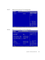
B.1
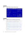
BIOS Main Menu Selections
B–2
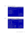
B.2
BIOS Advanced Menu Selections
B–2
B.2.0.1
BIOS Advanced Menu Main
B.2.0.2
BIOS Advanced Menu CPU Configuration
Sun Blade X6270 Server Module Service Manual • September 2010
B–3
B–3
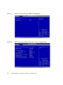
B.2.0.3
BIOS Advanced Menu On-board SATA Configuration
B–4
B.2.0.4
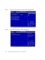
BIOS Advanced Menu ACPI Configuration
B.2.0.5
BIOS Advanced Menu Event Logging Details
B.2.0.6
BIOS Advanced Menu IPMI Configuration
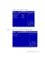
B.2.0.7
BIOS Advanced Intel VT-d Configuration
B.2.0.8
BIOS Advanced Menu LAN Configuration
B–7
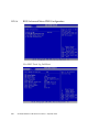
B.2.0.9
BIOS Advanced Menu MPS Configuration
B–8
B.2.0.10
BIOS Advanced Menu Remote Access Configuration
B–8
B.2.0.11
BIOS Advanced Menu Trusted Computing
B–9
B.2.0.12
BIOS Advanced Menu USB Configuration
B–9
B.3
BIOS PCI Menu Selections
B.4
BIOS Boot Menu
B–5
B–6
B–7
B–10
B–10
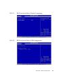
B.4.0.1
BIOS Boot Menu Main
B.4.0.2
BIOS Boot Menu Boot Settings Configuration
B.4.0.3
BIOS Boot Menu Boot Device Priority
B.4.0.4
BIOS Boot Menu Option ROM
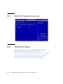
B.4.0.5
BIOS Boot Menu Wake On LAN
B.5
BIOS Security Menu
B.6
BIOS Chipset Menu Settings
B.7
B–4
B–11
B–11
B–12
B–12
B–13
B–14
B–14
B.6.0.1
BIOS Chipset Main Menu
B.6.0.2
BIOS Chipset Menu CPU Bridge Configuration
B.6.0.3
BIOS Chipset Menu NorthBridge Configuration
B–16
B.6.0.4
BIOS Chipset Menu SouthBridge Configuration
B–16
BIOS Exit Menu
C. Connector Pinouts
B–15
B–15
B–17
C–1
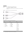
C.1
3–Cable Dongle Pinouts
C–2
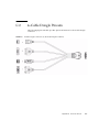
C.2
4–Cable Dongle Pinouts
C–3
Contents
vii
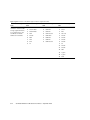
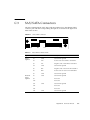
C.3
SAS/SATA Connectors
C.4
SAS Diskplane
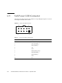
C.5
SAS Power/LED Connector
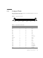
C.6
Compact Flash
Index
viii
C–5
C–7
C–8
C–9
Index–1
Sun Blade X6270 Server Module Service Manual • September 2010
Preface
The Sun Blade X6270 Server Module Service Manual contains information and
procedures for maintaining and upgrading the Sun Blade™ X6270 Server Module.
Before You Read This Document
It is important that you review the safety guidelines in the Sun Blade X6270 Server
Module Safety and Compliance Guide (820-4411) and in the Important Information for Sun
Hardware Systems (816-7190).
Product Updates
For product updates that you can download for the Sun Blade X6270 Server Module,
please visit the following web site:
http://www.sun.com/download/
Find the Hardware Drivers section and click x64 Servers & Workstations. The Sun
Blade X6270 Server Module site contains updates for firmware and drivers, as well as
CD-ROM ISO images.
ix
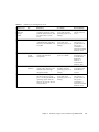
Related Documentation
The documents listed in the following table are available online at:
http://docs.sun.com/app/docs/prod/blade.x6270
x
Title
Content
Part Number
Format
Sun Blade X6270 Server
Module Product Notes
Late-breaking information
about the server module
820-6179
PDF
HTML
Sun Blade X6270 Server
Module Getting Started Guide
Basic installation information
for setting up the server
module
820-6181
PDF
Print
Sun Blade X6270 Server
Module Installation Guide
Detailed installation
information for setting up the
server module
820-6175
PDF
HTML
Print option
Sun Blade X6270 Server
Module Linux, VMware, and
Solaris Operating Systems
Installation Guide
Installation instructions for
the Linux, VMware, and
Solaris operating systems
820-6176
PDF
HTML
Sun Blade X6270 Server
Module Windows Operating
System Installation Guide
Installation instructions for
the Windows Server
operating system
820-6177
PDF
HTML
Sun Installation Assistant for
Linux and Windows User’s
Guide
Instructions for using the Sun
Installation Assistant (SIA)
when installing a Windows or
Linux operating system
820-3357
PDF
HTML
Sun Blade X6270 Server
Module Service Manual
Information and procedures
for maintaining and
upgrading the server module
820-6178
PDF
HTML
x64 Servers Utilities Reference
Manual
Information for using
applications and utilities
common to x64 servers and
server modules
820-1120
PDF
HTML
Sun x64 Servers Diagnostics
Guide
Information about how to use
the diagnostic software tools
provided with x64 servers
820-6750
PDF
HTML
Sun Blade X6270 Server Module Service Manual • September 2010
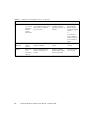
Title
Content
Part Number
Format
Sun Integrated Lights Out
Manager 3.0 document
collection
These documents cover ILOM
features and tasks that are
common to servers and
server modules that support
ILOM 3.0.
820-5523
820-6410
820-6411
820-6412
820-6413
PDF
HTML
Sun Integrated Lights Out
Manager 2.0 User’s Guide
ILOM features and tasks that
are common to servers and
server modules that support
ILOM
820-1188
PDF
HTML
Sun Integrated Lights Out
Manager (ILOM) Supplement
for Sun Blade X6270 Server
Module
ILOM information that is
specific to the server module
820-6180
PDF
HTML
Important Safety Information
for Sun Hardware Systems
Multilingual hardware safety
and compliance information
for all Sun hardware systems
816-7190
Print
Translated versions of some of these documents are available at the web site
described above in French, Simplified Chinese, and Japanese. English documentation
is revised more frequently and might be more up-to-date than the translated
documentation.
Documentation, Support, and Training
Sun Function
URL
Sun Documentation
http://docs.sun.com
Support
http://www.sun.com/support/
Training
http://www.sun.com/training/
Preface
xi
Typographic Conventions
Typeface*
Meaning
Examples
AaBbCc123
The names of commands, files,
and directories; on-screen
computer output
Edit your.login file.
Use ls -a to list all files.
% You have mail.
AaBbCc123
What you type, when contrasted
with on-screen computer output
% su
Password:
AaBbCc123
Book titles, new words or terms,
words to be emphasized.
Replace command-line variables
with real names or values.
Read Chapter 6 in the User’s Guide.
These are called class options.
You must be superuser to do this.
To delete a file, type rm filename.
* The settings on your browser might differ from these settings.
Using UNIX Commands
This document might not contain information about basic UNIX® commands and
procedures such as shutting down the system, booting the system, and configuring
devices. Refer to the following for this information:
■
Software documentation that you received with your system
■
Solaris™ Operating System documentation, which is at:
http://docs.sun.com
xii
Sun Blade X6270 Server Module Service Manual • September 2010
Sun Welcomes Your Comments
Sun is interested in improving its documentation and welcomes your comments and
suggestions. You can submit your comments by going to:
http://www.sun.com/hwdocs/feedback
Please include the title and part number of your document with your feedback:
Sun Blade X6270 Server Module Service Manual, part number 820-6178-11
Preface
xiii
xiv
Sun Blade X6270 Server Module Service Manual • September 2010
CHAPTER
1
Sun Blade X6270 Hardware and
Software Features
This chapter summarizes the features available on the Sun Blade X6270 Server
Module and contains the following topics:
■
Section 1.1, “Server Hardware and Software Features” on page 1-2
■
Section 1.2, “Server Indicators and Buttons” on page 1-4
■
Section 1.3, “Attaching Devices To the Server” on page 1-5
■
Section 1.4, “Replaceable Server Components” on page 1-7
1-1
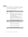
1.1
Server Hardware and Software Features
TABLE 1-1 summarizes the standard configurations and optional components
available for the Sun Blade X6270 Server Module.
TABLE 1-1
Server Hardware and Software Features
X6270 Server
Module
Standard Server
Components
Shipped
Description
The following standard components are shipped on the Sun Blade X6270
Server Module:
• Service Processor (SP). One SP per server. SP provides remote KVMS
functionality, IPMI baseboard management controller (BMC)
functionality, and interfaces to the chassis monitoring module (CMM).
The SPs and CMM work together to form a complete server module
and chassis management system.
• Indicators and Buttons. The Sun Blade X6270 Server Module includes
standard service indicator LEDs and buttons.
• Flexible I/O Network Connectivity. Supported I/O network
connectivity can include these optional components: Fabric expansion
module, chassis network express modules, and chassis PCI express
modules.
• Front Panel I/O Device Connection. The Sun Blade X6270 Server
Module front panel provides a universal connection port for attaching
devices directly to the server using a dongle cable.
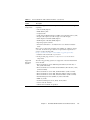
Preinstalled CPU Servers are typically ordered and shipped with preinstalled memory and
and DIMM
CPU configurations. Some of the preinstalled memory and CPU
Configurations
assemblies offered (and shipped) for the Sun Blade X6270 Server Module
can include:
• 2 Xeon Quad-Core E5520 CPU – 2.26GHz, Turbo, 80W
• 4GB Memory – 2x 2GB DDR3 1066MHz DIMMs
or
• 2 Xeon Quad-Core E5540 CPU – 2.53GHz, Turbo, 80W
• 12GB Memory – 6 x 2GB DDR3 1066MHz DIMMs
or
• 2 Xeon Quad-Core X5570 CPU –2.93GHz, Turbo, 95W
• 24GB Memory – 6 x 4GB DDR3 1333MHz DIMMs
1-2
Sun Blade X6270 Server Module Service Manual • September 2010
TABLE 1-1
Server Hardware and Software Features (Continued)
X6270 Server
Module
Optional Server
Components
Description
The following optional server components may be ordered and shipped
separately:
• CPU Assembly Options
• DDR3 Memory Kits
• Compact Flash
• SATA and SAS Hard Disk Drives (HDDs) and Solid State Drives (SSD)
• Dongle Cable Options (3-Cable Dongle or 4-Cable Dongle)
• Fabric Expansion Module (FEM) Options
• RAID Expansion Module (REM) Options
• Operating System Software
• Printed Documentation - Sun Blade X6270 Server Module Installation
Guide.
Note - Server components and their part numbers are subject to change
over time. For the most up-to-date list of replaceable components for
servers, see the following URL:
http://sunsolve.sun.com/handbook_pub/Systems/
1. Click the name and model of your server.
2. In the product page, click Full Components List for the list of
components.
Supported
Operating
Systems
The following operating systems are supported on the Sun Blade X6270
Server Module.
• Microsoft Windows Server 2003 Enterprise Edition (R2 with SP2, or
SP2) (32-bit and 64-bit)
• Microsoft Windows Server 2003 Standard Edition (R2 with SP2, or SP2)
(32-bit and 64-bit)
• Microsoft Windows Server 2008, Standard Edition (32-bit or 64-bit)
• Microsoft Windows Server 2008, Enterprise Edition (32-bit or 64-bit)
• Microsoft Windows Server 2008, Datacenter Edition (32-bit or 64-bit)
• Red Hat Enterprise Linux (RHEL) 4.7, 32-bit and 64-bit
• RHEL 5.3, 64-bit
• SUSE Linux Enterprise Server (SLES) 10 SP2, 64-bit
• Solaris 10 10/08 and later
• VMware ESX and ESXi 3.5 Update 4
Chapter 1
Sun Blade X6270 Hardware and Software Features
1-3
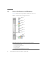
1.2
Server Indicators and Buttons
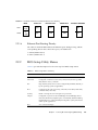
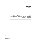
FIGURE 1-1 identifies the front panel buttons and indicators on the server.
FIGURE 1-1
Sun Blade X6270 Server Module Front Panel
1
2
3
4
5
6
7
8
9
10
Figure Legend Sun Blade X6270 Server Module Front Panel LEDs and Buttons
1-4
1
Server Locate LED
2
Server Ready-to-Remove LED
3
Server Service Action Required LED
4
Server OK Power LED
5
Server Power Button
6
Non-Maskable Interrupt (NMI) dump button (Service Only)
Sun Blade X6270 Server Module Service Manual • September 2010
Figure Legend Sun Blade X6270 Server Module Front Panel LEDs and Buttons (Continued)
7
Universal connection port (UCP)
8
Storage device (hard disk drive or solid state drive) OK Power LED
9
Storage device Service Action Required LED
10
Storage device Ready-to-Remove LED
Caution – Do not use the NMI button unless you are instructed to do so by
authorized Sun Service personnel. The NMI button sends an NMI dump request to
the CPUs, which is used by Sun Field Service for debugging activities at the request
of Sun Service personnel.
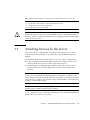
1.3
Attaching Devices To the Server
Your system chassis is shipped with a dongle cable that enables you to connect
communication devices directly to the front panel of the Sun Blade X6270 Server
Module.
The Sun Blade X6270 Server Module supports one of two types of dongle cables:
■
3-Cable Dongle II (P/N 530-3936 Option # 4622A). This cable provides a VGA
connector, RJ-45 serial connector, and one dual USB connector.
■
4-Cable Dongle (P/N 530-3934 Option # 4621A). This cable provides a VGA
connector, DB-9 serial connector, RJ-45 serial connector, and one dual USB
connector.
Note – The RJ-45 serial connector on the 4-Cable Dongle (Option# 4621A) is not
functional on the Sun Blade Sun Blade X6270 Server Module. To establish a local
serial connection with the Sun Blade X6270 Server Module, you should use the RJ-45
serial connector available on the 3-Cable Dongle (Option# 4622A) or the DB-9 serial
connector on the 4-Cable Dongle.
Note – The 3-Cable Dongle II is typically provided with each Sun Blade 6000 or 6048
Chassis System. Additional cables may be ordered.
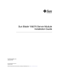
FIGURE 1-2 illustrates how to attach the 3-Cable Dongle to the Sun Blade X6270 Server
Module universal connection port (UCP).
Chapter 1
Sun Blade X6270 Hardware and Software Features
1-5
FIGURE 1-2
Server Front Panel I/O Connection Using 3-Cable Dongle
1
2
3
Figure Legend 3-Cable Dongle Connectors
1
Dual USB 2.0 connectors
2
RJ-45 Serial port connector
3
VGA video connector
Caution – The dongle cable should be used only for configuration and service
purposes. It should be disconnected from the server module when the configuration
or servicing operation is completed.
1-6
Sun Blade X6270 Server Module Service Manual • September 2010
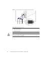
1.4
Replaceable Server Components
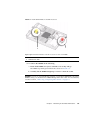
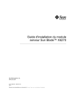
FIGURE 1-3 identifies the replaceable component locations on the Sun Blade X6270
Server Module, with the top cover removed.
FIGURE 1-3
Sun Blade X6270 Server Module Replaceable Component Locations
2
3
4
5
1
6b
6a
7
8
9
Figure Legend Replaceable Server Components
1
System battery
2
Fabric Expansion Module (FEM) (optional component)
3
Midplane connector
4
Raid Expansion Module (REM) (optional component)
Chapter 1
Sun Blade X6270 Hardware and Software Features
1-7
Figure Legend Replaceable Server Components (Continued)
1-8
5
Compact Flash Module (optional component)
The Compact Flash Module is shown in FIGURE 1-3 under the REM.
6a
DIMMs (optional components)
The DIMMs in FIGURE 1-3 are shown populated in DIMM slots 2, 5, 8 for each CPU.
Note - Processor chip contains memory controller. Do not attempt to populate DIMMs
sockets next to unpopulated (empty) CPU sockets.
6b
DIMM filler panels
DIMM filler panels shown populated in DIMM slots 0, 1, 3, 4, 6 and 7.
Note - The DIMM filler panels should remain in unpopulated DIMM slots until the
DIMM filler panel can be replaced with a DIMM. Otherwise, you may experience a
reduction in system performance.
7
CPU heatsinks (up to two CPUs may be installed)
The minimum CPU configuration shipped includes one CPU with a heatsink. An air
baffle is shipped to cover the empty CPU socket (not shown in FIGURE 1-3).
Additional CPUs may be ordered.
Note - In the example shown in FIGURE 1-3, the CPUs are installed under the two
heatsinks.
8
REM battery (optional component)
9
Storage devices (hard disk drives or solid state drives)
Up to four optional storage devices may be installed.
Sun Blade X6270 Server Module Service Manual • September 2010
CHAPTER
2
Powering On and Configuring BIOS
Settings
This chapter describes how to power on and off the server, as well as how to
configure BIOS settings.
The following topics are discussed in this chapter.
■
■
Section 2.1, “Powering On and Off the Server” on page 2-2
■
Section 2.1.1, “Power On the Server Module” on page 2-2
■
Section 2.1.3, “Troubleshoot Server Power States” on page 2-4
■
Section 2.1.2, “Power Off and Verify Server Is Ready for Removal From
Chassis” on page 2-3
■
Section 2.1.4, “Wake On LAN – Remote Power On” on page 2-5
Section 2.2, “About The BIOS” on page 2-6
■
Section 2.2.1, “BIOS Booting and Set Up Considerations” on page 2-6
■
Section 2.2.2, “BIOS Setup Utility Menus” on page 2-13
■
Section 2.2.3, “Enabling Support for Common BIOS Settings” on page 2-15
■
Section 2.2.4, “Updating the BIOS Firmware” on page 2-22
2-1
2.1
Powering On and Off the Server
Refer to the following topics in this section to power on and off a server:
2.1.1
■
Section 2.1.1, “Power On the Server Module” on page 2-2
■
Section 2.1.2, “Power Off and Verify Server Is Ready for Removal From Chassis”
on page 2-3
■
Section 2.1.3, “Troubleshoot Server Power States” on page 2-4
■
Section 2.1.4, “Wake On LAN – Remote Power On” on page 2-5
Power On the Server Module
The following procedure assumes the server module is installed in a powered-on
chassis.
1. Verify that the server is in a standby power state.
In a Standby power state, the OK power LED on the front panel of the server
blinks (0.1 second on, 2.9 seconds off). A standby power state indicates that the
server module SP is active but the server module host is powered-off.
See FIGURE 1-1 for the OK Power LED location.
Note – The OK/Power LED will be set to standby blink only when there is enough
chassis power for the server module to power on. If there is not enough chassis
power, the OK/Power LED will remain off until there is enough power for the server
module to power on. To troubleshoot this issue, see “Troubleshoot Server Power
States” on page 4.
2. Apply full power to the server SP and host.
For example:
■
Local server power-on. Use a non-conductive pointed object or stylus to press
and release the recessed Power button on the server module front panel.
For Power button location, see FIGURE 1-1 “Sun Blade X6270 Server Module
Front Panel” on page 4.
■
2-2
ILOM SP web interface power-on. Log in to the ILOM web interface for the
server SP and select: Remote Control --> Remote Power Control -->Power On.
Sun Blade X6270 Server Module Service Manual • September 2010
■
ILOM SP CLI power-on. Log in to the SP ILOM CLI and type: start /SYS
The OK/Power LED on the server module front panel illuminates a steady-on
green light. The steady-on LED state indicates that the server module SP and host
are both powered-on.
If the server does not power-on, see “Troubleshoot Server Power States” on
page 4.
2.1.2
Power Off and Verify Server Is Ready for Removal
From Chassis
Follow these steps to ensure that the server is properly powered off and is ready for
removal from chassis.
1. Power off the server.
For example:
■
Graceful shutdown from local server. Use a stylus (or other pointed object) to
press and release the Power button on the front panel.
This operation will cause any Advanced Configuration and Power Interface
(ACPI) enabled operating systems to perform an orderly shutdown of the
operating system. Servers not running ACPI-enabled operating systems will
shut down to standby power mode immediately.
■
Emergency shutdown from local server. Press and hold the Power button for at
least five seconds to force the main power off.
■
ILOM CLI shutdown. Log in to the SP ILOM CLI and type:
stop /SYS
■
ILOM web interface shutdown. Log in to the ILOM web interface for the
server SP and do the following:
a.Select Remote Control --> Remote Power Control.
b. Select one of the following actions from the drop-down list.
-- Immediate Power Off: Select to power off the server.
-- Graceful Shutdown and Power Off: Select to gracefully shut down the
system operating system before the system is powered off.
Refer to the Sun Integrated Lights Out Manager 2.0 User’s Guide (820-1188) for
more information.
2. To ensure that the system is powered off and ready to be removed from the
chassis, do the following:
Chapter 2
Powering On and Configuring BIOS Settings
2-3
a. Verify that the green power LED on the front panel of the server is in
standby or off state.
b. Ensure that the system was prepared for removal on the Component
Management tab in ILOM.
In the Component Management tab, a Ready (no power) status will appear in
the Ready To Remove column for the server.
For more details, see the prepare to remove component procedures in the Sun
Integrated Lights Out Manager 2.0 Users Guide (820-1188).
For information about removing the server from the chassis and removing the
cover from the server, see “Removing the Server From the Chassis and Removing
the Cover” on page 5.
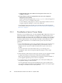
2.1.3
Troubleshoot Server Power States
Each time a server module powers on in the Sun Blade 6000 or 6048 Series Chassis, it
queries the CMM to ensure that there is enough power available from the power
supply units (PSUs) to power on the server. If there is not enough power to power on
the server module, the SP denies the server module from receiving power (standby
and main). If this situation occurs, the OK/Power LED on the front panel of the
server module will remain off. To troubleshoot this power issue, follow these
guidelines:
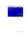
1. Review the ILOM Event Log messages to determine if the server has permission to
power on. An event message is recorded in the log any time there is not an
adequate amount of power available from the PSUs to power on the server
module.
For more information about the ILOM event log or monitoring power
consumption, refer to the Sun Integrated Lights Out Manger 2.0 User’s Guide
(820-1188).
2. Ensure that the system chassis has the proper amount of power supplies installed
to support powering on all the chassis components currently installed.
Refer to the system chassis documentation for information about the number of
power supplies required to power on chassis components.
3. To avoid power loss, it is recommended that you use the default CMM power
management settings for PSUs in ILOM.
For more information about power management, refer to the Sun Blade X6270
Server Module ILOM 2.0 Supplement Guide (820-6180) and the Sun Integrated Lights
Out Manger 2.0 (ILOM 2.0) User’s Guide (820-1188).
2-4
Sun Blade X6270 Server Module Service Manual • September 2010
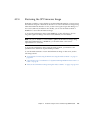
2.1.4
Wake On LAN – Remote Power On
Wake On LAN (WOL) enables you to power on a server from another location over a
network connection. Specifically this feature provides the ability for the network
controller in the server to power the server on when a "magic packet" is received over
the network from a remote system.
2.1.4.1
WOL Set Up Requirements
1. The Wake On LAN (WOL) feature in the Boot menu of the BIOS must be enabled.
For details, see “Enabling Support for Wake ON LAN” on page 2-16.
2. The server must be installed in a chassis that has an established connection to an
active power source.
For details about how to install the power supply modules in a chassis and
connect them to an active power source, see the documentation supplied with
your chassis.
3. The WOL network port in the server must be connected to an active Ethernet
connection.
For details about how to install a chassis network module and connect it to an
active Ethernet connection, see the documentation supplied with your chassis.
4. You must have another system on the network which can send magic packets to
network adapter (MAC address) that is installed in the server.
Typically you could use a magic packet program to send the packets over the
network to wake a shutdown (WOL-enabled) server. For more details about how
to send a magic packet over the network to a WOL-enabled server, refer to the
documentation supplied with the magic packet program.
5. Test the WOL implementation by ensuring the magic packet sent over the network
powers on the server.
If the test fails, verify that your network environment supports magic packets. For
instance, some switches and routers may block magic packets.
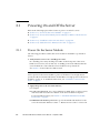
Chapter 2
Powering On and Configuring BIOS Settings
2-5
2.2
About The BIOS
The Basic Input/Output System (BIOS) has a setup utility stored in the BIOS flash
memory. The setup utility reports system information and can be used to configure
the BIOS settings. The configurable data is provided with context-sensitive help and
is stored in the system's battery-backed CMOS RAM. If the configuration stored in
the CMOS RAM is invalid, the BIOS settings return to their default optimal values.
There are seven menus in the BIOS Setup Utility, which appear in this order: Main,
Advanced, PCI, Boot, Security, Chipset, and Exit. To navigate the menus or options
listed on the menu, use the arrow keys. The options or fields that you can configure
on a menu appear in color. For further instructions on how to navigate and change
settings in the BIOS Setup Utility, refer to the online instructions provided on the
menu.
For additional information about the BIOS operations and menu options available on
your server, refer to the following sections:
2.2.1
■
Section 2.2.1, “BIOS Booting and Set Up Considerations” on page 2-6
■
Section 2.2.2, “BIOS Setup Utility Menus” on page 2-13
■
Section 2.2.3, “Enabling Support for Common BIOS Settings” on page 2-15
■
Section 2.2.4, “Updating the BIOS Firmware” on page 2-22
BIOS Booting and Set Up Considerations
Refer to the following sections for information when booting the BIOS and other
set up considerations:
2-6
■
Section 2.2.1.1, “Default BIOS Power-On Self-Test (POST) Events” on page 2-7
■
Section 2.2.1.2, “BIOS POST F1 and F2 Errors” on page 2-8
■
Section 2.2.1.3, “How BIOS POST Memory Testing Works” on page 2-11
■
Section 2.2.1.4, “PCI Express ExpressModule Slot Booting Priority” on page 2-12
■
Section 2.2.1.5, “Ethernet Port Device and Driver Naming” on page 2-12
■
Section 2.2.1.6, “Ethernet Port Booting Priority” on page 2-13
Sun Blade X6270 Server Module Service Manual • September 2010
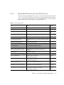
2.2.1.1
Default BIOS Power-On Self-Test (POST) Events
At system startup, the BIOS performs a power-on self-test that checks the hardware
on your server to ensure that all components are present and functioning properly.
TABLE 2-1 identifies the events that can occur during BIOS POST, as well as specifies
whether these event can prevent the host from powering-on.
TABLE 2-1
BIOS POST Events
Event
Cause
Boot continues
on host?
User password violation
Attempt to enter password fails three times
No
Setup password violation
Attempt to enter password fails three times
No
Correctable ECC
Correctable ECC (error correction code) error detected
Does not
apply
Uncorrectable ECC
Uncorrectable ECC error detected
Does not
apply
No system memory
No physical memory detected in the system
No
No usable system memory
All installed memory has experienced an unrecoverable
failure
No
Hard disk controller failure
No disk controller found
Yes
Keyboard failure
Keyboard cannot be initialized
Yes
Boot media failure
No removable boot media is found
Yes
No video device
No video controller is found
No
Firmware (BIOS) ROM corruption
BIOS checksum fails and the boot block is not
corrupted
No
System restart
System boot initiated
Yes
Initiated by hard reset
Boot process started by hard reset
Yes
Memory initialization
Memory sizing is occurring.
System firmware progress
Does not
apply
Primary processor initialization
Primary CPU initialization
System firmware progress
Does not
apply
Initiated by warm reset
Boot process started by warm reset
Does not
apply
Embedded controller management
Management controller initialization
Does not
apply
Secondary processor(s) initialization
Secondary CPU initialization asserted
System firmware progress
Does not
apply
Chapter 2
Powering On and Configuring BIOS Settings
2-7
TABLE 2-1
BIOS POST Events (Continued)
Boot continues
on host?
Event
Cause
Video initialization
When BIOS initializes keyboard
Does not
apply
Keyboard controller initialization
When BIOS initializes keyboard
Does not
apply
Option ROM initialization
BIOS initializes Option ROMs
System firmware progress
Does not
apply
Option ROM space exhausted
BIOS cannot copy an option to the memory
Yes
User initiated system set up
End user initiated access to BIOS Setup Utility
System firmware progress
Does not
apply
User initiated boot to OS
System boot initiated
System firmware progress
Does not
apply
No bootable media
Nothing to boot from
No
PXE server not found
Boot error - PXE server not found
F12 key was pressed but BIOS fails to boot from PXE
server
No
ACPI Power state
Soft-off power applied
Does not
apply
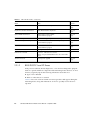
2.2.1.2
BIOS POST F1 and F2 Errors
Each power-on-self-test (POST) diagnostic is a low-level test designed to pinpoint
faults in a specific hardware component. If the POST diagnostics discloses an F1 or
F2 error, it typically reports the following information about the error:
■
Type of error detected
■
When or where the error occurred
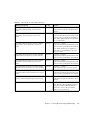
TABLE 2-2 lists some of the F1 and F2 error messages that could appear during the
POST diagnostics along with instructions for how to possibly resolve the error
reported.
2-8
Sun Blade X6270 Server Module Service Manual • September 2010
TABLE 2-2
BIOS POST F1 and F2 Error Messages
BIOS POST Error Message
Error Type
Resolution
Uncorrectable Error Detected on Last Boot:IOH(0)
Protocol Error (Please Check SP Log for more
Details)
IOH error
• Press F1 to continue.
• Check the SP event log in ILOM for more
details.
Uncorrectable Error Detected on Last Boot:IOH(0)
QPI [x] Error (Please Check SP Log for more
Details)
IOH error
• Press F1 to continue.
• Check the fault management function and
the SP event log in ILOM for more details.
Note - Where QPI [x] equals 0 for QPI Link
0 or 1 for QPI Link 1.
Uncorrectable Error Detected on Last Boot:IOH(0)
PCI-E [x] Error (Please Check SP Log for more
Details)
IOH error
• Press F1 to continue.
• Check the fault management function and
the SP event log in ILOM for more details.
Note - Where PCI-E [x] port number can
range from 1 to 10 depending on the PCI
root port on IOH.
Uncorrectable Error Detected on Last Boot:IOH(0)
ESI Error (Please Check SP Log for more Details)
IOH error
• Press F1 to continue.
• Check the fault management function and
the SP event log in ILOM for more details.
Uncorrectable Error Detected on Last Boot:IOH(0)
Thermal Error (Please Check SP Log for more
Details)
IOH error
• Press F1 to continue.
• Check the fault management function and
the SP event log in ILOM for more details.
Uncorrectable Error Detected on Last Boot:IOH(0)
DMA Error (Please Check SP Log for more Details)
IOH error
• Press F1 to continue.
• Check the SP event log for more details.
Uncorrectable Error Detected on Last Boot:IOH(0)
Miscellaneous Error (Please Check SP Log for more
Details)
IOH error
• Press F1 to continue.
• Check the fault management function and
the SP event log in ILOM for more details.
Uncorrectable Error Detected on Last Boot:IOH(0)
VTd Error (Please Check SP Log for more Details)
IOH error
• Press F1 to continue.
• Check the SP event log in ILOM for more
details.
BMC Not Responding
ILOM error
• Press F1 to continue.
Note - This error message might display if
during the SP/BIOS communication an
internal error occurs. This error might
require you to restart the SP.
Chapter 2
Powering On and Configuring BIOS Settings
2-9
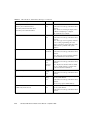
BIOS POST F1 and F2 Error Messages (Continued)
TABLE 2-2
BIOS POST Error Message
Error Type
•
•
•
•
IDE/ATAPI • Press F1 to continue.
error
• Check the SP event log in ILOM for more
details.
Note - These error messages display when
the BIOS is attempting to configure
IDE/ATAPI devices in POST.
Primary Master Hard Disk Error
Primary Slave Hard Disk Error
Secondary Master Hard Disk Error
Secondary Slave Hard Disk Error
Resolution
Timer Error
8254 timer
error
• Press F1 to continue.
• Check the SP event log in ILOM for more
details.
Note - This type of error typically indicates
an error while programming the count
register of channel 2 of the 8254 timer. This
could indicate a problem with system
hardware.
RAM R/W test failed
Memory
test failure
• Press F1 to continue.
• Check the SP event log in ILOM for more
details.
Note - This type of error typically indicates
that the RAM read/write test failed.
KBC BAT Test failed
Keyboard
controller
basic
assurance
test error
• Press F1 to continue.
• Check the SP event log in ILOM for more
details.
Note - Keyboard controller BAT test failed.
This error might indicate a problem with
keyboard controller initialization.
Display memory test failed
Video
display
error
• Press F1 to continue.
• Check the SP event log in ILOM for more
details.
CMOS Battery Low
CMOS
battery
error
• Press F2 to enter BIOS Setup Utility to
load system defaults.
• Check the SP event log in ILOM for more
details.
• If necessary, replace CMOS battery.
• CMOS Checksum Bad
• CMOS Date/Time Not Set
CMOS
error
• Press F2 to enter BIOS Setup Utility to
load system defaults.
• Check the SP event log in ILOM for more
details.
2-10
Sun Blade X6270 Server Module Service Manual • September 2010
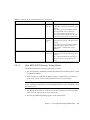
TABLE 2-2
BIOS POST F1 and F2 Error Messages (Continued)
BIOS POST Error Message
Error Type
Resolution
Password check failed
Password
check error
• Press F1 to continue.
• Check the SP event log in ILOM for more
details.
Note - This type of error indicates that the
password entered does not match the
password specified in the BIOS Setup
Utility. This condition might occur for both
Supervisor and User password verification.
Keyboard/Interface Error
Keyboard
controller
error
• Press F1 to continue.
• Check the SP event log in ILOM for more
details.
Note - This type of error indicates that the
Keyboard Controller failure. This error
might indicate a problem with system
hardware.
S.M.A.R.T error on the drive
S.M.A.R.T
• Press F1 to continue.
device error • Check the SP event log in ILOM for more
details.
Note - S.M.A.R.T. failure messages might
indicate the need to replace the storage
device.
2.2.1.3
How BIOS POST Memory Testing Works
The BIOS POST memory testing is performed as follows:
1. The first megabyte of DRAM is tested by the BIOS before the BIOS code is copied
from ROM to DRAM.
2. After existing out of DRAM, the BIOS performs a simple memory test (where a
write/read of every location with the pattern 55aa55aa is performed).
Note – The simple memory test is performed only if Quick Boot is not enabled from
the Boot Settings Configuration screen. Enabling Quick Boot causes the BIOS to skip
the memory test.
3. The BIOS polls the memory controllers for both correctable and non-correctable
memory errors and logs those errors into the SP.
4. The message, BMC Responding appears at the end of POST.
Chapter 2
Powering On and Configuring BIOS Settings
2-11
2.2.1.4
PCI Express ExpressModule Slot Booting Priority
The Sun Blade X6270 Server Module supports up to two chassis PCI Express
ExpressModules (PCIe EMs) per server module.
The chassis slots for the PCIe Express Modules are detected by the BIOS during
startup in this order: PCIe EM BLn.1 and PCIe EM BLn.0. For example, if the server
is in slot 3, the BIOS boot priority is 3.1, 3.0.
See the chassis documentation for further information on PCIe EMs.
2.2.1.5
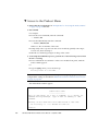
Ethernet Port Device and Driver Naming
The Sun Blade X6270 Server Module supports up to two 10/100/1000BASE-T Gigabit
Ethernet ports provided by the network express modules (NEMs) installed in the
chassis. The lower NEM port is NET 0 and the upper NEM port is NET 1, as shown
in FIGURE 2-1.
If you have the InfiniBand NEM installed, only one Ethernet port per server module
will be available.
FIGURE 2-1
Ethernet Port Chassis Labeling Designations
NET 1
NET 0
For further information on NEMs, see the chassis documentation
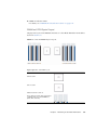
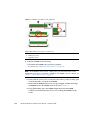
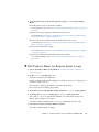
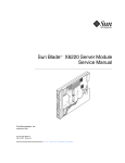
The device naming for the Ethernet interfaces is reported differently by different
interfaces and operating systems. FIGURE 2-2 for a diagram that explains the logical
(operating system) and physical (BIOS) naming conventions used for each interface.
Note – If you have an InfiniBand NEM, the Net 0 interfaces only are used.
2-12
Sun Blade X6270 Server Module Service Manual • September 2010
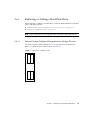
FIGURE 2-2
Sun Blade X6270 Server Module Ethernet Port Naming
BIOS
Solaris 10
Red Hat Linux
SUSE Linux
Windows 2003/2008
Net 1
slot
1F01
igb1
eth1
eth1
net2
Net 0
slot
1F00
igb0
eth0
eth0
net
2.2.1.6
Ethernet Port Booting Priority
The order in which the BIOS detects the Ethernet ports during bootup, and the
corresponding drivers that control those ports, are listed below:
1. NET 0 (INTEL NIC 0)
2. NET 1 (INTEL NIC 1)
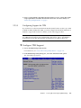
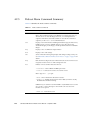
2.2.2
BIOS Setup Utility Menus
TABLE 2-3 provides descriptions for the seven top-level BIOS setup menus.
TABLE 2-3
BIOS Setup Menus Summary
Menu
Description
Main
General system information.
Advanced
Configuration interface for the CPUs, SATA, ACPI, Event Log, IPMI,
MPS, Remote Access, and USB.
PCI
Plug-and-Play (PnP) devices can be configured by the BIOS (default), or
by the operating system (if applicable).
Boot
Configure the boot device priority (CD/DVD, removables, hard disks,
solid state disks, networks).
Security
Install or change the user and supervisor passwords.
Chipset
Configuration options for the NorthBridge and SouthBridge devices.
Note that the Memory Chipkill option is enabled by default. Enabling
Chipkill improves system reliability but degrades system performance
under specific applications.
Exit
Save or discard changes.
Chapter 2
Powering On and Configuring BIOS Settings
2-13
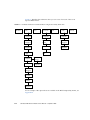
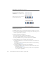
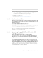
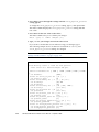
FIGURE 2-3 identifies the sub-menus that you can access from each of the seven
top-level BIOS menus.
Sun Blade X6270 Server Module BIOS Configuration Utility Menu Tree
FIGURE 2-3
Main menu
Advanced
menu
PCI
menu
Boot menu
Security
menu
Chipset
menu
CPU
Configuration
Boot Settings
Configuration
CPU Bridge
Configuration
SATA
Configuration
Boot Device
Priority
NorthBridge
Configuration
ACPI
Configuration
Option ROM
SouthBridge
Configuration
Event
Logging
Wake On
LAN
IPMI
Configuration
BMC
Event Log
Intel VT-d
LAN
Configuration
Exit menu
MPS
Configuration
Remote
Access Type
Trusted
Computing
USB
Configuration
For an example of the options that are available on the BIOS Setup Utility menus, see
Appendix B.
2-14
Sun Blade X6270 Server Module Service Manual • September 2010
2.2.3
Enabling Support for Common BIOS Settings
This section includes instructions for:
2.2.3.1
■
Section 2.2.3.1, “Accessing the BIOS Setup Utility Menus” on page 2-15
■
Section 2.2.3.2, “Enabling Support for Wake ON LAN” on page 2-16
■
Section 2.2.3.3, “Configuring Support for TPM” on page 2-17
■
Section 2.2.3.4, “Configuring SP LAN Settings” on page 2-19
■
Section 2.2.3.5, “Configuring Option ROM Settings in BIOS” on page 2-21
Accessing the BIOS Setup Utility Menus
The following procedures describes the steps for accessing the BIOS Setup Utility
menus.
▼ Access BIOS Setup Utility Menus
1. Power-on or power-cycle the server.
2. To enter the BIOS Setup Utility, press the F2 key while the system is
performing the power-on self-test (POST).
Note – If there is an error during the boot process, you can press F1 to access the
BIOS Setup Utility.
Alternatively, you can also use the following hot key combinations when accessing
the BIOS Setup Utility from a serial connection:
■
F1 - Ctrl Q
■
F2 - Ctrl E.
■
F7 Control-D
■
F8 Control-P
■
F9 Control-O
■
F10 Control-S
■
F12 Control-N
The BIOS Setup Utility dialog appears.
Chapter 2
Powering On and Configuring BIOS Settings
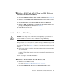
2-15
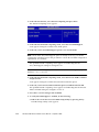
2.2.3.2
Enabling Support for Wake ON LAN
After installing the operating system, you might want to consider enabling the Wake
On LAN (WOL) option in the BIOS Setup Utility. This features enables you to power
on the server from another location over the network.
▼ Enable or Disable WOL in BIOS
1. Access the BIOS Setup Utility menus.
For instructions, see “Access BIOS Setup Utility Menus” on page 2-15.
2. In the BIOS Setup Utility menus, use the arrow keys (or Tab key) to navigate to
the Boot menu.
3. In the Boot menu, highlight the Wake ON LAN setting, and then press Enter.
A tab appears listing the Wake ON LAN options, one for each network port.
4. In the tab, enable the appropriate port (for example, NET0 WAKE ON LAN for
network port 0), then press Enter and do one of the following:
■
Select Enabled to enable the Wake On LAN setting.
or
■
Select Disabled to disable the Wake On LAN setting.
5. Press F10 to save and exit.
2-16
Sun Blade X6270 Server Module Service Manual • September 2010
6. Prior to testing whether the Wake ON LAN feature is active, ensure that all the
setup requirements for Wake ON LAN have been met. For more details, see
“WOL Set Up Requirements” on page 5.
2.2.3.3
Configuring Support for TPM
If you intend to use the Trusted Platform Module (TPM) feature set that is provided
in Windows 2003 and Windows 2008, you must configure the Sun Blade X6270 Server
Module to support this feature. For details, see the following procedure.
Note – TPM enables you to administer the TPM security hardware in your server.
For additional information about implementing this feature, refer to the Windows
Trusted Platform Module Management documentation provided by Microsoft.
▼ Configure TPM Support
1. Access the BIOS Setup Utility menus.
For instructions, see “Access BIOS Setup Utility Menus” on page 2-15
2. In the BIOS Setup Utility dialog box, select the Advanced menu option.
The Advanced page appears.
Chapter 2
Powering On and Configuring BIOS Settings
2-17
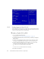
3. In the Advanced menu, select Trusted Computing and press Enter.
The Trusted Computing screen appears.
4. In the Advanced Trusted Computing menu, select the TCG/TPM Support.
A tab appears listing the available TCG/TPM options.
5. In the tab, set the TCG/TPM Support option to Yes and click OK.
Note – Even if the TCG/TPM Support option is already set to Yes, you should
complete the remaining steps in this procedure to ensure that all TPM configuration
requirements are satisfied.
The updated Trusted Computing screen appears and indicating that the
TCG/TPM Support setting has changed to Yes.
Note – In the above dialog box, the Execute TPM Command setting is set, by
default, to [Don’t Change].
6. In the Advanced Trusted Computing menu, select the Execute TPM Command
and press Enter.
A tab appears listing the available Execute TPM Command options.
7. In the tab, set the Execute TPM Command option to Enabled and click OK.
The updated Trusted Computing screen appears and indicating that the Execute
TPM Command setting has changed to Enabled.
8. Press F10 to save the changes and exit BIOS.
9. To verify that TPM support is enabled, do the following:
a. Reboot the server then access the BIOS Setup Utility by pressing F2 key.
The BIOS Setup Utility screen appears.
2-18
Sun Blade X6270 Server Module Service Manual • September 2010
b. In the BIOS Setup Utility dialog box, select Advanced --> Trusted Computing
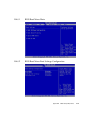
and press Enter.
The updated Trusted Computing screen appears indicting that TPM Support is
set to Yes and TPM Enable Status is set to Enabled.
10. Press F10 to exit BIOS.
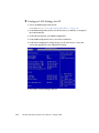
2.2.3.4
Configuring SP LAN Settings
You can assign an IP address for the server SP from the BIOS Setup Utility on the
IPMI LAN configuration menu. Alternatively, you can also specify the LAN settings
for the SP using ILOM. For instructions for setting the IP address in ILOM, see the
Sun Integrated Lights Out Manager 2.0 User’s Guide.
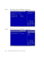
To set the IP address in the BIOS Setup Utility, use the menus to navigate to the LAN
configuration setting as follows: Advanced --> IPMI Configuration --> LAN
Configuration. See FIGURE 2-3 for menu navigation tree.
Chapter 2
Powering On and Configuring BIOS Settings
2-19
▼ Configure LAN Settings for SP
1. Access the BIOS Setup Utility menus.
For instructions, see “Access BIOS Setup Utility Menus” on page 2-15.
2. In the BIOS Setup Utility menus, use the arrow keys (or Tab key) to navigate to
the Advanced menu.
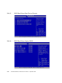
3. In the Advanced menu, select IPMI Configuration.
4. In the IPMI Configuration menu, select LAN Confutation.
5. In the LAN Configuration settings dialog, use the arrow keys to select and
specify the appropriate LAN configuration settings.
6. Press F10 to save the changes and exit.
2-20
Sun Blade X6270 Server Module Service Manual • September 2010
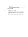
2.2.3.5
Configuring Option ROM Settings in BIOS
The BIOS Option ROM is 128 kbytes. Of these 128 kbytes, approximately 80 kbytes
are used by the VGA controller, the disk controller, and the network interface card.
Approximately 48 kbytes remain for the Option ROM.
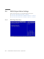
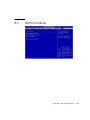
▼ Enable or Disable Option ROM Settings
1. Access the BIOS Setup Utility menus.
For instructions, see “Access BIOS Setup Utility Menus” on page 2-15.
2. In the BIOS Setup Utility menus, use the arrow keys (or Tab key) to navigate to
the Boot menu.
The Boot menu appears.
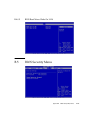
3. In the Boot menu, highlight the Option ROM setting, and then press Enter.
4. In the Boot menu listing the Option ROM settings, highlight the applicable
Option ROM setting to modify, then press Enter.
A tab appears listing the available settings.
5. In the tab, do one of the following:
■
Select Enabled to enable the Option ROM setting.
or
■
Select Disabled to disable the Option ROM setting.
6. Press F10 to save and exit.
Chapter 2
Powering On and Configuring BIOS Settings
2-21
2.2.4
Updating the BIOS Firmware
The BIOS is updated whenever you update the ILOM SP firmware. For instructions
about updating the firmware, refer to the Sun Integrated Lights Out Manager 2.0 User’s
Guide (820-1188).
2-22
Sun Blade X6270 Server Module Service Manual • September 2010
CHAPTER
3
Maintaining the Sun Blade X6270
Server
This chapter contains information and procedures for servicing the Sun Blade X6270
Server Module hardware.
This chapter contains the following topics:
■
Section 3.1, “Tools and Supplies Needed” on page 3-2
■
Section 3.2, “Avoid Electrostatic Discharge” on page 3-2
■
Section 3.3, “Removing or Replacing Filler Panels” on page 3-3
■
Section 3.4, “Removing the Server From the Chassis and Removing the Cover” on
page 3-5
■
Section 3.5, “Locations of Replaceable Components” on page 3-8
■
Section 3.6, “Replaceable Component Procedures” on page 3-10
■
Section 3.6.1, “Replacing or Adding a Hard Disk Drive” on page 3-11
■
Section 3.6.2, “Replacing the System Battery” on page 3-15
■
Section 3.6.3, “Replacing the Compact Flash Module” on page 3-17
■
Section 3.6.4, “Replacing or Upgrading Memory Modules (DIMMs)” on
page 3-18
■
Section 3.6.5, “Adding a RAID Expansion Module” on page 3-26
■
Section 3.6.6, “Adding or Replacing a Fabric Expansion Module” on page 3-33
■
Section 3.6.7, “Replacing or Upgrading the CPU” on page 3-34
■
Section 3.6.8, “Replacing Motherboard Enclosure” on page 3-38
3-1
3.1
Tools and Supplies Needed
You can service the server with the following items:
3.2
■
Allen wrench
■
No. 2 phillips screwdriver
■
Adjustable-setting torque driver (5–20 in.-lbs)
■
Antistatic wrist strap
■
Stylus, or other pointed object (to press the recessed Power button)
Avoid Electrostatic Discharge
Internal modules and options are electronic components that are extremely sensitive
to static electricity. Ordinary amounts of static from your clothes or work
environment can destroy components.
To prevent static damage whenever you are accessing any of the internal
components, you must:
■
■
3-2
Place static sensitive components such as hard drives, blades, and server hardware
options on an antistatic surface. The following items can be used as an antistatic
surface:
■
The bag used to ship the component
■
Sun Electronic Discharge (ESD) mat, Sun part number 250-1088
Use the antistatic wrist strap that is supplied with each server. Attach this wrist
strap to your wrist and ground the other end of strap to the system chassis (sheet
metal). For additional information, see the instructions that are shipped with the
strap.
Sun Blade X6270 Server Module Service Manual • September 2010
3.3
Removing or Replacing Filler Panels
Each server module arrives with module-replacement filler panels for CPUs, storage
drives, and memory modules. These filler panels are installed at the factory and must
remain in the server until you are ready to replace them with a purchased module.
A filler panel is a metal or plastic enclosure that does not contain any functioning
system hardware or cable connectors. These panels must remain in any unused
module slots (storage drives, DIMMs, servers, and CPUs) to ensure proper airflow
throughout the system. If you remove a filler panel and continue to operate your
system with an empty module slot, the operating performance for your system could
decline.
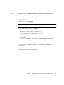
3.3.1
Remove or Insert Filler Panels
TABLE 3-1 identifies how to remove or insert server module replacement filler panels
TABLE 3-1
Filler Panel Replacement Procedures
Filler Panel Module Remove Procedure
Install Procedure
Server Module
1. Locate the vacant server module slot in the
chassis.
2. Ensure that the release lever is fully opened,
then align the filler panel with the vacant server
module slot.
3. Slide the filler panel into the vacant server
module slot.
As the release lever makes contact with the
chassis, the lever will start to rise.
4. Close the release lever until it locks the filler
panel in place.
1. Locate the server module filler panel
to be removed from the chassis.
2. To unlatch the server module filler
panel from the chassis, press the
button on the release lever handle,
then lower the lever into the fully
open position.
3. To remove the filler panel from the
chassis, hold the release lever then
gently slide the filler panel toward
you.
Memory Module 1. Locate the memory module filler panel 1. Locate the vacant memory module slot on the
to be removed from the motherboard.
motherboard.
2. Simultaneously press down on both
2. Ensure that ejector levers at both ends of the
ejector levers at the ends of the
memory module slot are in a fully opened
memory module slot.
position.
3. Lift the filler panel straight up to
3. Align the memory module filler panel with
remove it from the memory module
with the empty slot, then gently press the filler
socket.
panel into slot until both ejector levers close,
locking the filler panel in place.
Chapter 3
Maintaining the Sun Blade X6270 Server
3-3
Filler Panel Replacement Procedures (Continued)
TABLE 3-1
Filler Panel Module Remove Procedure
Install Procedure
Storage Drive
Module*
1. Locate the disk drive filler panel to be 1. Locate the vacant disk drive module slot in the
removed from the server.
server, then ensure that the release lever on the
filler panel is fully opened.
2. To unlatch the disk drive filler panel,
press
the
release
lever
button
then
tilt
2.
Slide
the filler panel into the vacant slot by
*Hard disk drive
the lever up into the fully opened
pressing the middle of the filler panel faceplate
or solid state
position.
with your thumb or finger.
drive
3. To remove the filler panel from the
The release lever will rise as it makes contact
slot, hold the opened release lever and
with the chassis. Do not slide the filler panel in
gently slide the filler panel toward
all the way. Leave the filler panel out
you.
approximately 0.25 to 0.50 inch (6 to 12 mm)
from the opening.
3. Using your thumb or finger, press on the
middle of the filler panel faceplate until the
release lever engages with the chassis.
4. Close the release lever until it clicks into place
and is flush with the front of the server.
CPU
Air Baffle
(over empty
CPU socket)
1. Use an Allen wrench (4 mm) to loosen 1. Lower the air baffle over the CPU socket, and
the two mounting screws.
align the holes for the mounting screws on the
motherboard.
2. Gently pull up the air baffle to expose
the empty CPU socket.
2. Insert the two mounting screws, then use an
Allen wrench (4 mm) to tighten the screws.
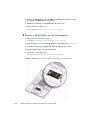
Note – For instructions for adding or replacing chassis component filler panels (for
example: network modules or chassis monitoring modules), consult the
documentation supplied with your chassis.
3-4
Sun Blade X6270 Server Module Service Manual • September 2010
3.4
Removing the Server From the Chassis
and Removing the Cover
Use the preparatory procedures in this section when you are referred to them from
the removal and replacement procedures.
Caution – Do not operate the system with empty slots. Always insert a filler panel
into an empty slot to reduce the possibility of system shut down.
3.4.1
Remove Server Module From Chassis
To replace components for the Sun Blade X6270 Server Module, with the exception of
the hard disk drives, you need to remove the server module from the chassis.
Note – If you are only replacing the hard disk drives in the server, you can skip this
section and go to “Replacing or Adding a Hard Disk Drive” on page 3-11.
Caution – Before handling internal components of the server module, attach an
electrostatic-discharge (ESD) wrist strap to the grounding post that is built into the
rear of the chassis. The system’s printed circuit boards and hard disk drives contain
components that are extremely sensitive to static electricity.
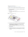
1. Power off the server and verify that the server is ready to be removed from
chassis.
For instructions, see “Power Off and Verify Server Is Ready for Removal From
Chassis” on page 2-3.
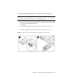
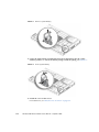
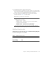
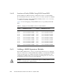
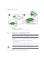
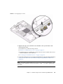
2. Perform the following steps to remove the server from the chassis.
See FIGURE 3-1.
a. To open the ejector levers on the server: 1) press the green ejector button at
the top and bottom to unlatch the server from chassis; then 2) swing out the
top and bottom levers.
b. To slide the server from the chassis: 1) hold the opened ejector levers and
pull the ejector levers toward you; then 2) grasp the server with both hands
and slide it toward you away from the chassis.
Chapter 3
Maintaining the Sun Blade X6270 Server
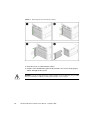
3-5
FIGURE 3-1
Removing the Server From the Chassis
3. Place the server on a flat antistatic surface.
4. Install a server module filler panel in the unused server slot to ensure proper
airflow throughout the system.
Caution – If you operate the chassis with an empty server module slot, it is possible
that you will notice a reduction in the performance of your system.
3-6
Sun Blade X6270 Server Module Service Manual • September 2010
3.4.2
Remove or Install Server Cover
Refer to the following instructions for removing or installing the cover on the server.
■
“Remove Cover From Server” on page 3-7
■
“Install Cover on Server” on page 3-7
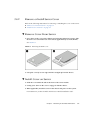
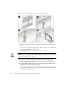
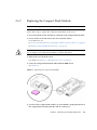
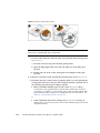
▼ Remove Cover From Server
1. Press down on the cover release button and, using the indent for leverage, slide
the main cover toward the rear of the chassis approximately 0.5 inch (12 mm).
See FIGURE 3-2.
FIGURE 3-2
Removing the Main Cover
2. Grasp the cover by its rear edge and lift it straight up from the chassis.
▼ Install Cover on Server
1. Slide the cover under the tabs at the front of the server module.
2. Gently press down on the cover to engage it with the chassis.
3. When applicable, install the server in the chassis and power on the system.
For instructions, see the Sun Blade X6270 Server Module Installation Guide.
Chapter 3
Maintaining the Sun Blade X6270 Server
3-7
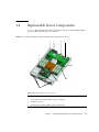
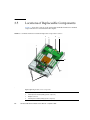
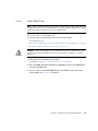
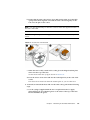
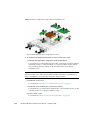
3.5
Locations of Replaceable Components
FIGURE 3-3 shows the locations of the replaceable Sun Blade X6270 Server Module
components that are documented in this chapter.
FIGURE 3-3
Sun Blade X6270 Server Module Replaceable Component Locations
2
4
3
5
1
6b
6a
8
7
9
s
Figure Legend Replaceable Server Components
3-8
1
System battery
2
Fabric Expansion Module (FEM) (optional component)
3
Midplane connector
4
Raid Expansion Module (REM) (optional component)
Sun Blade X6270 Server Module Service Manual • September 2010
Figure Legend Replaceable Server Components (Continued)
5
Compact Flash Module (optional component)
The Compact Flash Module under the REM.
6a
DIMMs (optional components)
The DIMMs are shown populated in DIMM slots 2, 5, 8 for each CPU.
Processor chip contains memory controller. Do not attempt to populate DIMMs sockets next to
unpopulated (empty) CPU sockets.
6b
DIMM filler panels
DIMM filler panels shown populated in DIMM slots 0, 1, 3, 4, 6 & 7.
The DIMM filler panels should remain in unpopulated DIMM slots until the DIMM filler panel can be
replaced with a DIMM. Otherwise, you may experience a reduction in system performance.
7
CPU heatsinks (up to two CPUs may be installed)
The minimum CPU configuration shipped includes one CPU with a heatsink. An air baffle is shipped
to cover the empty CPU socket (not shown in FIGURE 3-3). Additional CPUs may be ordered.
In the example shown in FIGURE 3-3, the CPUs are installed under the two heatsinks.
8
REM battery (optional components)
9
Storage devices (hard disk drives (HDD) or solid state drives (SSD)
Up to four hard disk drives or solid state drives may be populated.
Chapter 3
Maintaining the Sun Blade X6270 Server
3-9
3.6
Replaceable Component Procedures
Note – Some of the procedures in this section are for customer-replaceable units
(CRUs) and some are for field-replaceable units (FRUs), as noted in the procedures
and in the list below. FRU components must be replaced only by trained Sun service
technicians. Contact your Sun Service representative for assistance with FRU
replacements.
Note – Supported components and their part numbers are subject to change over
time. For the most up-to-date list of replaceable components for the Sun Blade X6270
Server Module, click on the X6270 Server Module product page at:
http://sunsolve.sun.com/handbook_pub/Systems/
This section contains procedures for replacing the following components:
■
“Replacing or Adding a Hard Disk Drive” on page 3-11 (CRU)
■
“Replacing the System Battery” on page 3-15 (CRU)
■
“Replacing the Compact Flash Module” on page 3-17(CRU)
■
“Replacing or Upgrading Memory Modules (DIMMs)” on page 3-18 (CRU)
■
“Adding a RAID Expansion Module” on page 3-26 (CRU)
■
“Adding or Replacing a Fabric Expansion Module” on page 3-33 (CRU)
■
“Replacing or Upgrading the CPU” on page 3-34 (FRU)
■
“Replacing Motherboard Enclosure” on page 3-38 (FRU)
Caution – Before handling components, attach an ESD wrist strap to the grounding
post that is built into the rear of the chassis. The system’s printed circuit boards and
hard disk drives contain components that are extremely sensitive to static electricity.
3-10
Sun Blade X6270 Server Module Service Manual • September 2010
3.6.1
Replacing or Adding a Hard Disk Drive
When replacing or adding a hard disk drive on the Sun Blade X6270 Server Module
refer to following sections:
■
“Internal System Software Designation for Storage Devices” on page 3-11
■
“Replace or Add HDD or SSD” on page 3-12
Note – This component is a hot-swappable CRU and can be replaced by anyone.
3.6.1.1
Internal System Software Designation for Storage Devices
The internal system software designation for storage devices (hard disk drives
(HDD) or solid state drives (SSD) is shown in FIGURE 3-4.
Designation of HDDs or SSD
FIGURE 3-4
2
0
3
1
Chapter 3
Maintaining the Sun Blade X6270 Server
3-11
3.6.1.2
HDD or SSD Failure and RAID
A single storage device failure does not cause a data failure if the storage devices are
configured as a mirrored RAID 1 volume (optional). The storage device can be
removed, and when a new storage device is inserted, the contents are automatically
rebuilt from the rest of the array with no need to reconfigure the RAID parameters. If
the replaced storage drive was configured as a hot-spare, the new HDD is
automatically configured as a new hot-spare.
Caution – Possible data loss: If you insert an storage device that has been
configured with a RAID volume into a server that did not previously have its storage
devices configured with RAID volumes, the existing storage devices in the server
will be converted to RAID volumes during automatic synchronization and any
existing data on the existing storage devices in the server are erased. Before you
permanently remove a storage device from the server that is part of an active RAID
volume, you should delete the active RAID volume from the storage device. For
information on how to delete a RAID volume, use the appropriate RAID
management utility for the RAID controller installed.
For information about the implementation of RAID on this server and references to
RAID controller documentation, refer to the Sun Disk Management Overview For X64
Sun Fire and Sun Blade Series Servers (820-6350).
3.6.1.3
Replace or Add HDD or SSD
Use the following procedure to replace a HDD or SSD.
1. Observe the LEDs on the front panel of the HDD to verify which HDD in the
server is defective.
1 2
3
Figure Legend HDD LEDs
3-12
1
HDD or SSD Power OK LED - green (operational)
2
HDD or SSD Service Action Required - amber (faulty disk requiring service)
3
HDD or SSD Ready to Remove - blue (HDD or SSD has been prepared for removal from server)
Sun Blade X6270 Server Module Service Manual • September 2010
2. To remove the faulty HDD from the server, perform the following steps:
Note – The Sun Blade X6270 Server Module HDDs are hot-swappable, which means
that you can remove them while the server is running. However, you must prepare
the operating system on the server prior to removing the HDD.
a. Press the release lever button on the HDD (or SDD) front panel then tilt the
lever up into a fully opened position.
For example:
■
If removing HDD (or SSD) when server is out of chassis, see FIGURE 3-5.
or
■
If removing HDD (or SSD) when server is in chassis, see FIGURE 3-6.
FIGURE 3-5
Remove Storage Device When Server Module Is Out of Chassis
Chapter 3
Maintaining the Sun Blade X6270 Server
3-13
FIGURE 3-6
Remove Storage Device When Server Module is in Chassis
b. Hold the opened release lever and gently slide the HDD (or SDD) toward
you.
c. If you are not immediately replacing the HDD (or SDD), insert a filler panel
into the empty HDD slot on the server,.
For details, see “Remove or Insert Filler Panels” on page 3-3.
Caution – Do not operate the server with empty storage device slots. Always insert
a filler panel into an empty storage device slot. For more information, see “Removing
or Replacing Filler Panels” on page 3-3.
3. To install (or reinstall) the HDD (or SDD), perform the following steps:
a. Ensure that the HDD (or SSD) release lever is in a fully opened position.
b. Slide the HDD (or SSD) into the vacant slot by pressing the middle of the
HDD faceplate with your thumb or finger.
The release lever will rise as it makes contact with the chassis. Do not slide the
storage device in all the way. Leave the storage device out approximately 0.25
to 0.50 inch from the opening.
3-14
Sun Blade X6270 Server Module Service Manual • September 2010
c. Using your thumb or finger, press on the middle of the HDD (or SSD)
faceplate until the release lever engages with the chassis.
d. Close the release lever until it clicks into place and is flush with the front of
the server.
Note – If the storage devices were previously configured as a mirrored RAID 1 array,
an automatic resynchronization is invoked and the contents are automatically rebuilt
from the rest of the array with no need to reconfigure the RAID parameters. If the
replaced storage device was configured as a hot-spare, the new HDD is automatically
configured as a new hot-spare.
3.6.2
Replacing the System Battery
Note – This component is a CRU and can be replaced by anyone.
Follow these steps to replace the system battery on the server.
1. Power off the server and remove it from the chassis.
For instructions, see:
■
“Power Off and Verify Server Is Ready for Removal From Chassis” on page 2-3
■
“Remove Server Module From Chassis” on page 3-5
Caution – After removing the server from the chassis always insert a filler panel
into the empty slot to avoid a possible reduction in system performance.
2. Remove the cover from the server.
For details, see “Remove or Install Server Cover” on page 3-7.
3. To remove the system battery do the following:
Caution – Removing the system battery will clear the CMOS and return the BIOS
settings to their factory defaults. The BIOS will automatically notify you of this
change the next time you boot the system.
a. Using your fingers, unlatch the battery from the socket by twisting the
battery away from the socket spring.
b. Lift the battery up and out of the socket, see FIGURE 3-7.
Chapter 3
Maintaining the Sun Blade X6270 Server
3-15
FIGURE 3-7
Remove System Battery
4. Locate the replacement system battery then insert the battery into the socket
with the positive (+) side of the battery facing toward the spring, see FIGURE 3-8.
FIGURE 3-8
Insert System Battery
5. Install the cover on the server.
For instructions, see “Install Cover on Server” on page 3-7.
3-16
Sun Blade X6270 Server Module Service Manual • September 2010
3.6.3
Replacing the Compact Flash Module
Note – This component is a CRU and can be replaced by anyone.
Follow these steps to replace the Compact Flash module on the server.
1. If necessary, back up any data that is contained on the Compact Flash module.
2. Power off the server and remove the server from the chassis.
For instructions, see:
■
“Power Off and Verify Server Is Ready for Removal From Chassis” on page 2-3
■
“Remove Server Module From Chassis” on page 3-5.
Caution – Do not operate the system with empty slots. Always insert a filler panel
into an empty slot to reduce the possibility of system shut down.
3. Remove the cover from the server.
For details, see “Remove or Install Server Cover” on page 3-7.
4. Locate the Compact Flash module underneath the REM board.
See FIGURE 3-9.
FIGURE 3-9
Replacing the Compact Flash Module
5. To remove the Compact Flash module, use your thumb to gently push down on
the compact flash card then slide the card out toward you.
Chapter 3
Maintaining the Sun Blade X6270 Server
3-17
6. To install the Compact Flash module, do the following:
a. Locate the keys on the side of the Compact Flash card and align them with
the sides of the compact flash slot.
b. Slide the Compact Flash card into the slot until it locks into place.
7. Install the server cover.
For details, see “Install Cover on Server” on page 3-7.
3.6.4
Replacing or Upgrading Memory Modules
(DIMMs)
The Sun Blade X6270 Server Module are shipped with standard memory
configurations. If you ordered additional memory, a kit for the additional memory is
shipped separately.
When replacing or upgrading a DIMM on the Sun Blade X6270 Server Module, see
the following sections:
■
3.6.4.1
“Memory Module Installation Considerations” on page 3-18
■
“DIMM and CPU Physical Layout” on page 3-19
■
“DIMM Population Rules” on page 3-20
■
“DIMM Rank Classification Labels” on page 3-21
■
“Replace or Add DIMM” on page 3-22
■
“Error Correction and Parity” on page 3-25
■
“Inconsistencies Between DIMM Fault LEDs and the BIOS Mapping of Faulty
DIMMs” on page 3-25
■
“Locations of Faulty DIMMs Using ILOM Versus BIOS” on page 3-26
Memory Module Installation Considerations
The Sun Blade X6270 Server Module supports a variety of DIMM configurations that
can include single-rank (SR) DIMMs, dual-rank (DR) DIMMs, or quad-rank (QR)
DIMMs. When replacing or adding memory modules to the Sun Blade X6270 Server
Module, you should consider the following:
■
Physical layout of the DIMMs and CPUs
For details, see “DIMM and CPU Physical Layout” on page 3-19.
■
DIMM population rules
For details, see “DIMM Population Rules” on page 3-20.
3-18
Sun Blade X6270 Server Module Service Manual • September 2010
■
DIMM classification labels
For details, see “DIMM Rank Classification Labels” on page 3-21.
DIMM and CPU Physical Layout
The physical layout of the DIMMs and CPUs on a Sun Blade X6270 Server Module is
shown in FIGURE 3-10.
FIGURE 3-10
CPU and DIMM Physical Layout
Figure Legend CPU and DIMM Layout
CPU 0 location
CPU 1 location
Channel locations for CPU 0
Three channels per CPU with each channel
containing three color-coded DIMM slots
(black, white, and blue).
Chapter 3
Maintaining the Sun Blade X6270 Server
3-19
Figure Legend CPU and DIMM Layout (Continued)
Channel locations for CPU 1
Three channels per CPU with each channel
containing three color-coded DIMM slots (blue,
white and black).
P0:
DIMM slot numbering per CPU; with D8 as the
slot furthest away from processor.
P1:
DIMM Population Rules
The DIMM population rules for the Sun Blade X6270 Server Module are as follows:
1. Do not populate any DIMM socket next to an empty CPU socket. Each processor
contains a separate memory controller.
2. Each CPU can support a maximum of:
■
Nine dual-rank (DR) or single-rank (SR) DIMMs; or
■
Six quad-rank (QR) DIMMs with two per memory channel; or
■
Three QR DIMMs with one per channel and three DR or SR DIMMs.
3. Populate DIMMs by location according to the following rules:
■
Populate the DIMM slots for each memory channel that are the farthest from
the CPU first.
For example, populate D8/D5/D2 first; then D7/D4/D1 second; and finally,
D6/D3/D0. See FIGURE 3-10.
■
Populate QR DIMMs first, followed by SR or DR DIMMs.
■
Populate QR DIMMs in blue sockets (D8/D5/D2) first then white sockets
(D7/D4/D1). See FIGURE 3-10.
Note that QR DIMMs are supported only in white sockets if adjacent blue
socket contains a QR DIMM.
3-20
Sun Blade X6270 Server Module Service Manual • September 2010
4. For maximum performance, apply the following rules:
■
The best performance is ensured by preserving symmetry. For example, adding
three of same kind of DIMMs, one per memory channel, and ensuring that both
CPUs have the same size of DIMMs populated in the same manner.
■
In certain configurations, DIMMs will run slower than their individual
maximum speed. See TABLE 3-2 for further details.
TABLE 3-2
Memory Considerations and Limitations
1
DIMMs are available in two speeds: 1066 MHz and 1333 MHz.
2
DIMM speed rules are as follows:
3x DIMM per channel = 800 MHz
2x DIMM per channel = 1333 MHz (for single-rank and dual-rank DIMMs)
or = 800 MHz (for quad-rank DIMMs)
1x DIMM per channel = 1333 MHz (if using 1333 MHz DIMMs1)
1x DIMM per channel = 1066 MHz (if using 1066 MHz DIMMs)
3
The system operates all memory only as fast as the slowest DIMM configuration.
1
This DIMM configuration requires CPUs supporting 1333 MHZ.
DIMM Rank Classification Labels
DIMMs come in a variety of ranks: single, dual, or quad. Each DIMM is shipped with
a label identifying its rank classification. TABLE 3-3 identifies the corresponding rank
classification label shipped with each DIMM.
TABLE 3-3
DIMM Classification Labels
Rank Classification
Label
Quad-rank DIMM
4Rx4
Dual-rank DIMM
2Rx4
Single-rank DIMM
1Rx4
Chapter 3
Maintaining the Sun Blade X6270 Server
3-21
3.6.4.2
Replace or Add DIMM
Note – This component is a CRU and can be replaced by anyone.
Use the following procedure to replace a DIMM.
1. Power off the server and remove the server from the chassis.
For instructions, see:
■
“Power Off and Verify Server Is Ready for Removal From Chassis” on page 2-3
■
“Remove Server Module From Chassis” on page 3-5.
Caution – After removing the server from the chassis, ensure that a filler panel is
inserted into the empty server slot to reduce the possibility of a system shut down.
2. Remove the cover from the server.
For details, see “Remove or Install Server Cover” on page 3-7.
3. To replace a faulty DIMM, perform the following steps; otherwise, proceed to
Step 4.
a. Identify the location of the faulty DIMM by pressing the fault remind button
on the motherboard, see FIGURE 3-11.
3-22
■
If DIMM ejector LED is off: DIMM is operating properly.
■
If DIMM ejector LED is on (amber): DIMM is faulty and should be replaced.
Sun Blade X6270 Server Module Service Manual • September 2010
FIGURE 3-11
Fault Remind Button and LED Locations
1
2
Figure Legend Fault Remind Button and LED Locations for CPUs and DIMMs
1
Fault remind button
2
DIMM and CPU LEDs
b. To remove the DIMM do the following:
i. Rotate both DIMM slot ejectors outward as far as they will go.
The DIMM is partially ejected from the socket. See FIGURE 3-12.
ii. Carefully lift the DIMM straight up to remove it from the socket.
Caution – If you are not immediately inserting a replacement DIMM into the empty
DIMM socket, you should insert a DIMM filler panel in the socket. For more details,
see these sections, “Removing or Replacing Filler Panels” on page 3-3.
Chapter 3
Maintaining the Sun Blade X6270 Server
3-23
FIGURE 3-12
DIMM Socket Release and Alignment
Figure Legend DIMM Socket Release and Alignment
1
DIMM connector slot
2
DIMM connector key
3
DIMM ejector lever
4. To install a DIMM do the following:
a. Determine the DIMM socket location to populate.
For details, see “DIMM Population Rules” on page 3-20
Note – If the DIMM socket contains a filler panel, you will need to remove the
DIMM filler panel prior to installing a DIMM into the DIMM socket. For details, see
“Remove or Insert Filler Panels” on page 3-3
b. Ensure that the ejector lever at each end of the memory socket are fully open
(rotated outward) to accept the new DIMM.
c. Ensure that the DIMM ejector levers are open (angled outward) then align
the DIMM notch to the DIMM connector key. See FIGURE 3-12.
d. Using both thumbs, press the DIMM straight down into the DIMM
connector slot until both ejector levers close, locking the DIMM in to the
socket.
3-24
Sun Blade X6270 Server Module Service Manual • September 2010
Note – The DIMMs must be inserted evenly, straight down into the DIMM connector
slot, until the ejector levers lock into place.
e. Verify that the DIMM ejector levers are upright, seated, and tight. Press on
ejector levers to ensure that they are engaged properly.
5. Install the cover on the server.
For instructions, see “Install Cover on Server” on page 3-7.
3.6.4.3
Error Correction and Parity
The server’s processor provides parity protection on its internal cache memories and
error-correcting code (ECC) protection of the data. The system can detect and log the
following types of errors:
■
Correctable and uncorrectable memory ECC errors
■
Correctable and uncorrectable CPU internal errors
Advanced ECC corrects up to 4 bits in error on nibble boundaries, as long as they are
all in the same DRAM. If a DRAM fails, the DIMM continues to function.
Refer to the Sun Integrated Lights Out Manager 2.0 User’s Guide (820-1188) for
information on how to access the error log.
3.6.4.4
Inconsistencies Between DIMM Fault LEDs and the BIOS
Mapping of Faulty DIMMs
When a single DIMM is marked as faulty by ILOM (for example,
fault.memory.intel.dimm.training-failed is listed in the SP Event Log),
BIOS might map out the entire memory channel that contains the faulty DIMM as
failing, that is, up to three DIMMs. As a result, the memory available to the operating
system is reduced.
However, when the Fault Remind button is pressed, only the fault LED associated
with the faulty DIMM lights. The fault LEDs for the other two DIMMs in the memory
channel remain off. Therefore, you can correctly identify the faulty DIMM. When the
faulty DIMM is replaced and the DIMM fault is cleared using ILOM, the memory
available to the operating system returns to normal. For instructions for clearing
DIMM faults, see the Oracle Integrated Lights Out Manager (ILOM) 3.0 Supplement for
the Sun Blade X6270 M2 Server Module (821-0501).
Chapter 3
Maintaining the Sun Blade X6270 Server
3-25
3.6.4.5
Locations of Faulty DIMMs Using ILOM Versus BIOS
ILOM and BIOS use different formats to identify the location of a faulty DIMM.
■
For ILOM, the format is Px/Dx, where x is 0 or 1 for CPUs, and 0 to 8 for DIMMs.
■
For BIOS, the format is CPUx/CHANNELx/DIMMx, where x is 0 or 1 for CPUs,
and 0 to 2 for channels and DIMMs.
TABLE 3-4 shows the mapping of faulty DIMM locations as reported by ILOM and
BIOS.
TABLE 3-4
3.6.5
Mapping of Faulty DIMM Locations for ILOM and BIOS
ILOM Mapping
for CPU0
BIOS Mapping for CPU0
ILOM Mapping
for CPU1
BIOS Mapping for CPU1
P0/D0
CPU0/CHANNEL0/DIMM2
P1/D0
CPU1/CHANNEL0/DIMM2
P0/D1
CPU0/CHANNEL0/DIMM1
P1/D1
CPU1/CHANNEL0/DIMM1
P0/D2
CPU0/CHANNEL0/DIMM0
P1/D2
CPU1/CHANNEL0/DIMM0
P0/D3
CPU0/CHANNEL1/DIMM2
P1/D3
CPU1/CHANNEL1/DIMM2
P0/D4
CPU0/CHANNEL1/DIMM1
P1/D4
CPU1/CHANNEL1/DIMM1
P0/D5
CPU0/CHANNEL1/DIMM0
P1/D5
CPU1/CHANNEL1/DIMM0
P0/D6
CPU0/CHANNEL2/DIMM2
P1/D6
CPU1/CHANNEL2/DIMM2
P0/D7
CPU0/CHANNEL2/DIMM1
P1/D7
CPU1/CHANNEL2/DIMM1
P0/D8
CPU0/CHANNEL2/DIMM0
P1/D8
CPU1/CHANNEL2/DIMM0
Adding a RAID Expansion Module
When adding a REM card to a server, you must ensure that the server is equipped
with one or more SAS or SATA hard disk drives (HDDs) or solid state drives (SSDs)
in disk slots 0 through 3. For further information about the implementation and
configuration of RAID on this server, see the Sun Disk Management For x64 Sun Fire
and Sun Blade Series Servers Overview Guide (820-6350).
Caution – Back up all data to an external device prior to adding a REM to a server
that does not already have a REM installed.
3-26
Sun Blade X6270 Server Module Service Manual • September 2010
3.6.5.1
Add a REM Card
Note – The Sun Blade X6270 Server Module can be populated either with REM card
model 4620A, which uses a backup battery to store the system configuration, or REM
card model 4607A, which does not use a backup battery.
Follow these steps to add a REM card.
1. Power off the server and remove the server from the chassis.
For instructions, see:
■
“Power Off and Verify Server Is Ready for Removal From Chassis” on page 2-3
■
“Remove Server Module From Chassis” on page 3-5
Caution – After removing the server module from the chassis, ensure that a filler
panel is inserted into the empty server slot to reduce the possibility of a system
shutdown.
2. Remove the cover from the server module.
For details, see “Remove or Install Server Cover” on page 3-7.
3. On a new REM card 4620A installation, immediately remove the REM battery
from the new REM card.
4. Use two screws to attach the REM battery to the bracket at the front of the
server module (see FIGURE 3-13, location 1).
Chapter 3
Maintaining the Sun Blade X6270 Server
3-27
FIGURE 3-13
Possible REM Battery Locations
Figure Legend
1
REM battery installed on the bracket at the front of the server module
2
REM battery installed on the REM card
5. Connect the battery cable to the motherboard and REM card. See FIGURE 3-14.
3-28
Sun Blade X6270 Server Module Service Manual • September 2010
FIGURE 3-14
REM cable connected to the motherboard
6. Install the new REM card by sliding it at an angle into the support bracket, then
pressing it carefully into its connector. See FIGURE 3-15.
FIGURE 3-15
Insert REM card
Caution – Step 7 will remove all data from the system. Back up your data to an
external site before proceeding.
Chapter 3
Maintaining the Sun Blade X6270 Server
3-29
7. (Optional) If you want to switch your drives from SATA to SAS or from SAS to
SATA, you should replace the drives at this time.
For details, see “Replacing or Adding a Hard Disk Drive” on page 3-11.
8. Install the cover on the server.
For instructions, see “Install Cover on Server” on page 3-7.
9. Unless you have preloaded software on the SAS/SATA HDDs or SSDs, your
server will not have an operating system, or any data. You will need to restore
your data from backups, and install the operating system.
3.6.5.2
■
To install the Solaris Operating System or Linux Operating System, see the Sun
Blade X6270 Server Module Linux, VMware, and Solaris Operating Systems
Installation Guide (820-6176).
■
To install the Windows Operating System, see the Sun Blade X6270 Server
Module Windows Operating System Installation Guide (820-6177).
Replace a REM Card 4620A
With the cover off of the server module, determine whether the REM battery is
attached directly onto the motherboard (see FIGURE 3-13, location 1) or on the REM
card 4620A (see FIGURE 3-13, location 2).
▼ Replace a REM Card 4620A When the REM Battery Is
Installed on the REM Card
1. Remove the existing REM card by sliding it at an angle out of the support
bracket. See FIGURE 3-15.
2. Swap the REM battery from the existing REM card to the new REM card.
3. Replace the REM card by sliding the new card at an angle into the support
bracket, then pressing it carefully into its connector. See FIGURE 3-15.
4. Install the cover on the server.
For instructions, see “Install Cover on Server” on page 3-7.
3-30
Sun Blade X6270 Server Module Service Manual • September 2010
▼ Replace a REM Card 4620A When the REM Battery Is
Installed on the Motherboard
1. Disconnect the REM card battery cable from the motherboard (see FIGURE 3-14).
2. Remove the existing REM card by sliding the card at an angle out of the support
bracket. See FIGURE 3-15.
3. Reconnect the battery cable to the motherboard and the new REM card.
4. Replace the REM card by sliding it at an angle into the support bracket, then
pressing it carefully into its connector. See FIGURE 3-15.
5. Install the cover on the server.
For instructions, see “Install Cover on Server” on page 3-7.
3.6.5.3
Replace a REM Battery
Caution – This component is a CRU and can be replaced by anyone. Follow the
instructions in this section to ensure that the REM battery is properly installed.
Proper installation is required to ensure adequate cooling of the battery.
The REM battery should be replaced when indicated in the Sun StorageTek RAID
Manager Software User's Guide (820-1177). When replacing the REM battery, you will
find the existing battery installed in one of two locations—on the REM card, or on the
motherboard—as shown in FIGURE 3-13. Check your installation for the location of the
battery.
■
If the existing battery is installed on the REM card, install the replacement battery
onto the REM card.
■
If the existing battery is connected to the motherboard using the bracket which is
located toward the front of the server module, install the replacement battery onto
the bracket.
Follow these steps to replace the REM battery.
▼ Replace a REM Battery on the REM Card
1. Remove the cover from the server.
For details, see “Remove or Install Server Cover” on page 3-7.
2. Disconnect the REM cable and remove the REM card from the chassis.
Chapter 3
Maintaining the Sun Blade X6270 Server
3-31
3. Remove the REM battery from the REM card by removing the four screws
securing the old REM battery to the card.
4. Attach the new battery to the REM card with four screws.
5. Install the cover on the server.
For instructions, see “Install Cover on Server” on page 3-7.
▼ Replace a REM Battery on the Motherboard
1. Remove the cover from the server.
For details, see “Remove or Install Server Cover” on page 3-7.
2. Remove the two screws securing the battery to the bracket (see FIGURE 3-16).
3. Place the new battery on bracket and attach it using the two screws.
4. Plug the battery cable into the motherboard.
5. Install the cover on the server.
For instructions, see “Install Cover on Server” on page 3-7.
FIGURE 3-16
3-32
REM Battery Attached to Bracket and Plugged Into Motherboard
Sun Blade X6270 Server Module Service Manual • September 2010
3.6.6
Adding or Replacing a Fabric Expansion Module
Follow these steps to remove and replace a Fabric Expansion Module (FEM) in a Sun
Blade X6270 Server Module.
3.6.6.1
Replace or Add a FEM
Note – This component is a CRU and can be replaced by anyone.
Follow these steps to add or replace the FEM on the server.
1. Power off the server and remove the server from the chassis.
For instructions, see:
■
“Power Off and Verify Server Is Ready for Removal From Chassis” on page 2-3
■
“Remove Server Module From Chassis” on page 3-5.
Caution – After removing the server from the chassis insert a filler panel into an
empty slot to reduce the possibility of a system shutdown.
2. Remove the cover from the server.
For details, see “Remove or Install Server Cover” on page 3-7.
3. Perform one of the following:
■
Remove the existing FEM board.
or
■
Remove protective shipping cap from the FEM connector.
4. Perform the following steps to install the FEM board:
a. Slide the FEM board at an angle into the support bracket
b. Press the FEM board carefully into the connector.
See FIGURE 3-17.
Chapter 3
Maintaining the Sun Blade X6270 Server
3-33
FIGURE 3-17
Inserting the FEM Board
5. Install the cover on the server.
For details, see “Install Cover on Server” on page 3-7.
3.6.7
Replacing or Upgrading the CPU
Note – This component is a FRU and should be replaced only by qualified service
technicians. Contact your Sun service representative for assistance.
Follow these steps to replace a CPU and its heatsink in a Sun Blade X6270 Server
Module.
1. Power off the server and remove the server from the chassis.
For instructions, see:
■
“Power Off and Verify Server Is Ready for Removal From Chassis” on page 2-3
■
“Remove Server Module From Chassis” on page 3-5.
Caution – Do not operate the system with empty slots. Always insert a filler panel
into an empty slot to reduce the possibility of system shut down.
3-34
Sun Blade X6270 Server Module Service Manual • September 2010
2. Remove the cover from the server.
For details, see “Remove or Install Server Cover” on page 3-7.
3. To replace a faulty CPU, perform the following steps; otherwise, proceed to Step
4.
a. Press the fault remind button on the motherboard to illuminate the LED for
the CPU that has failed.
See FIGURE 3-18
■
If CPU LED is off: CPU is operational.
■
If CPU LED is lit (amber): CPU has encountered a fault condition and should
be replaced.
FIGURE 3-18
Fault Remind Button Location
b. To remove the heatsink covering the faulty CPU, perform the following steps:
i. Hold down the top of the heatsink to prevent it from tipping unevenly
while you alternately loosen the spring-loaded mounting screws that
secure the heatsink to the motherboard.
ii. Turn the screws 180 degrees at a time, and then remove the screws when
they are detached.
See FIGURE 3-19.
iii. Twist the heatsink slightly to lift it off the board. Turn the heatsink upside
down and allow the spring in each of the mounting holes to fall out into
your hand.
Chapter 3
Maintaining the Sun Blade X6270 Server
3-35
FIGURE 3-19
Remove Heatsink and CPU
Note – Set the heatsink upside down on a clean, flat surface to prevent the thermal
grease from contaminating other components.
c. To remove the faulty CPU from the CPU socket, perform the following steps:
See FIGURE 3-19.
i. Pivot the socket lever up, into the fully open position.
ii. Open the hinged plate that covers the CPU until it is in the fully open
position.
iii. Lift the CPU out of the socket, leaving the lever and plate in the open
position.
4. To install (or reinstall) a CPU, perform the following steps and see FIGURE 3-20.
a. Determine the CPU socket location to populate, then if you are replacing the
existing CPU with a new CPU proceed to Step 4b; otherwise, perform one of
the following tasks before proceeding to Step 4b:
■
Remove air baffle and filler panel in CPU socket. If you are adding a
second CPU to the motherboard for the first time and the CPU location is
covered by an air baffle, you will need to remove the air baffle and the filler
panel inside the CPU socket prior to adding the CPU. For instructions, see
“Remove or Insert Filler Panels” on page 3-3.
or
■
3-36
Clean old thermal grease from existing CPU. If you are reinstalling the
existing CPU, use an alcohol pad to clean all the old thermal grease from the
component surface.
Sun Blade X6270 Server Module Service Manual • September 2010
b. Ensure that the CPU socket release lever and retainer plate are in the fully
open position then align the CPU with the CPU socket and gently set the
CPU onto the pins in the socket.
Note – Use the alignment keys in the CPU socket to match the alignment notches on
the sides of the CPU.
Note – Mixing CPU speeds is not supported. Install two identical CPUs in your
server.
FIGURE 3-20
Install CPU and Heatstink
c. When the CPU is fully seated in the socket, pivot the hinged retainer plate
down onto the top of the CPU.
See the insert in the first (1) figure shown in FIGURE 3-20.
d. Pivot the release lever down and into the locked position, at the side of the
socket.
The release lever must lock down the retainer plate as you close the lever.
5. To install (or reinstall) the heat sink over the CPU socket, perform the following
steps.
a. Use the syringe (supplied with the new or replacement CPU) to apply
approximately 0.1 ml of thermal grease to the center of the top of the CPU.
Do not distribute the grease.
Chapter 3
Maintaining the Sun Blade X6270 Server
3-37
Note – System cooling might be affected by dust and contaminant build-up.
Therefore, you should open and check systems approximately every six months (or
more often in dirty operating environments). Check system heatsinks, fans, and air
openings. If necessary, clean systems by carefully brushing, blowing, or vacuuming
contaminants from the system.
b. Turn the heatsink upright and reinsert the mounting screws.
See the second (2) figure shown in FIGURE 3-20.
Caution – Avoid moving the heatsink after it has contacted the top of the CPU. Too
much movement could disturb the layer of thermal grease, leading to component
damage.
c. Carefully position and align the heatsink over the CPU.
Note – The heatsink is not symmetrical, and it must be aligned before you place it
on the CPU.
d. Lower the heatsink onto the CPU, aligning the mounting screws with their
holes on the motherboard.
e. Using an allen wrench, alternately tighten the two heatsink mounting screws,
180 degrees at a time, until each spring is completely compressed.
Tighten the screws to 7 in.-lbs (0.8 Nm).
6. Reinstall the cover on the server.
For details, see Section t, “Install Cover on Server” on page 3-7.
3.6.8
Replacing Motherboard Enclosure
Note – This component is a FRU and should be replaced only by qualified service
technicians. Contact your Sun Service representative for assistance.
To remove the motherboard enclosure from service or to return the motherboard
enclosure to service, follow these steps:
1. To remove the motherboard enclosure from service, perform the following:
3-38
Sun Blade X6270 Server Module Service Manual • September 2010
a. Power off the server and remove the server from the chassis.
For more information, see:
■
“Power Off and Verify Server Is Ready for Removal From Chassis” on
page 2-3
■
“Remove Server Module From Chassis” on page 3-5
Caution – Do not operate the system with empty slots. Always insert a filler panel
into an empty slot. If you continue to operate your system with an empty server
module slot, the operating performance for your system could decline.
b. Remove the cover from the server.
For details, see “Remove or Install Server Cover” on page 3-7.
c. Remove all replaceable components from the motherboard and place them on
an antistatic surface.
See FIGURE 3-21.
For instructions, see:
■
“Replacing or Upgrading Memory Modules (DIMMs)” on page 3-18
■
“Replacing or Upgrading the CPU” on page 3-34
■
“Replacing or Adding a Hard Disk Drive” on page 3-11
Caution – You must return each HDD to the bay from which it was removed. Use an
adhesive note or another method to temporarily label the HDDs after you remove
them.
■
“Adding a RAID Expansion Module” on page 3-26
■
“Adding or Replacing a Fabric Expansion Module” on page 3-33
Note – The server module enclosure, the motherboard, and hard drive backplanes
are all part of the motherboard FRU.
Chapter 3
Maintaining the Sun Blade X6270 Server
3-39
FIGURE 3-21
Remove Replaceable Components from Motherboard
The motherboard enclosure is prepared for service.
2. To return the motherboard enclosure to service, follow these steps:
a. Reinstall the replaceable components on the motherboard.
For instructions for reinstalling the replaceable components, see the procedures
referenced in Step 1c of this procedure; or see the procedures in the “Install
Server Module Options” chapter in the Sun Blade X6270 Server Module
Installation Guide.
Caution – If the HDDs contain RAID volumes, you should return each HDD to the
bay from which it was removed. The RAID volumes will remain on the drives as
long as the REM was not physically changed in this procedure.
b. Install the server cover.
For instructions, see “Remove or Install Server Cover” on page 3-7
c. Install the server module into a powered-on chassis.
For instructions, see “Install Server Module Into A Powered-On Chassis” in the
Sun Blade X6270 Server Module Installation Guide.
d. Power on the server.
For instructions, see “Power On the Server Module” on page 2-2.
3-40
Sun Blade X6270 Server Module Service Manual • September 2010
CHAPTER
4
Troubleshooting the Server and
Restoring ILOM Defaults
This chapter introduces the diagnostic tools you can use to troubleshoot or monitor
the performance of your server. It also includes information about how to restore the
SP password and serial connection defaults in ILOM, as well as how to restore your
ILOM SP firmware.
■
■
Section 4.1, “Troubleshooting the Server” on page 4-2
■
“Sun Diagnostic Tools” on page on page 4-2
■
“Diagnostic Tool Documentation” on page on page 4-5
Section 4.2, “Restoring ILOM Defaults” on page 4-6
■
“Accessing the Preboot Menu” on page on page 4-6
■
“Restoring the Factory Default ILOM Root Password” on page on page 4-12
■
“Restoring ILOM Access to the Serial Console” on page on page 4-13
■
“Restoring the SP Firmware Image” on page on page 4-15
■
“Preboot Menu Command Summary” on page on page 4-20
4-1
4.1
Troubleshooting the Server
The Sun Blade X6270 Server Module and its accompanying software and firmware
contain many diagnostic tools and features that can help you complete the following
tasks:
■
Isolate problems when a failure occurs on a customer replaceable-unit (CRU)
■
Monitor the status of a functioning system
■
Exercise the system to disclose more subtle problems that might be hardware
related
Sun provides a suite of diagnostic tools, each of which has its own specific strengths
and applications. For more information about which tool might be best to use for
your purpose, and where to locate information about these tools, see:
4.1.1
■
“Sun Diagnostic Tools” on page on page 4-2
■
“Diagnostic Tool Documentation” on page on page 4-5
Sun Diagnostic Tools
Sun provides a wide selection of diagnostic tools for use with your server. These
tools range from the SunVTS software, a comprehensive validation test suite, to log
files in ILOM that might contain clues helpful in identifying the possible sources of a
problem, and the fault management function in ILOM that enables you to identify a
faulted component as soon as the fault occurs.
The diagnostic tools also include standalone software packages, firmware-based tests
like power-on self-test (POST), U-Boot tests, or Pc-Check tests, and hardware LEDs
that tell you when the system components are operating.
TABLE 4-1 summarizes the variety of diagnostic tools that you can use when
troubleshooting or monitoring your server.
4-2
Sun Blade X6270 Server Module Service Manual • September 2010
TABLE 4-1
Summary of Sun Diagnostic Tools
Diagnostic Tool
Type
What It Does
Accessibility
Remote Capability
Integrated
Lights Out
Manager
(ILOM)
SP firmware
Monitors environmental
conditions, generates alerts,
performs fault isolation, and
provides remote console
access.
Can function on standby
power and when the
operating system is not
running.
Designed for
remote and local
access.
Preboot Menu
SP firmware
Enables you to restore some
of ILOM defaults (including
firmware) when ILOM is not
accessible.
Can function on standby
power and when
operating system is not
running.
Local, but remote
serial access is
possible if the SP
serial port is
connected to a
network-accessible
terminal server.
LEDs
Hardware
and SP
firmware
Indicate status of overall
system and particular
components.
Available when system
power is available.
Local, but sensor
and indicators are
accessible from
ILOM web
interface or
command-line
interface (CLI).
POST
Host
firmware
Tests core components of
system: CPUs, memory, and
motherboard I/O bridge
integrated circuits.
Runs on startup.
Available when the
operating system is not
running.
Local, but can be
accessed through
ILOM Remote
Console.
U-Boot
SP firmware
Initializes and test aspects of
the service processor (SP)
prior to booting the ILOM SP
operating system. Tests SP
memory, SP, network devices
and I/O devices.
Can function on standby
power and when
operating system is not
running.
Local, but remote
serial access is
possible if the SP
serial port is
connected to a
network-accessible
terminal server.
Chapter 4
Troubleshooting the Server and Restoring ILOM Defaults
4-3
Summary of Sun Diagnostic Tools (Continued)
TABLE 4-1
Diagnostic Tool
Type
What It Does
Accessibility
Remote Capability
Pc-Check
SP firmware
(or on Tools
and Driver
DVD for
systems
without SP)
DOS-based utility that tests
all motherboard components
(CPU, memory, and I/O),
ports, and slots.
Runs on startup.
Available when the
operating system is not
running.
Remote access
through ILOM
Remote Console
for servers shipped
with SP.
or
Local access for
servers shipped
without an SP (via
Tools and Driver
DVD).
Solaris
commands
Operating
system
software
Displays various kinds of
system information.
Requires operating
system.
Local, and over
network.
SunVTS
Diagnostic
tool
standalone
software
Exercises and stresses the
system, running tests in
parallel.
Requires operating
system. Install SunVTS
software separately.
View and control
over network.
4-4
Sun Blade X6270 Server Module Service Manual • September 2010
4.1.2
Diagnostic Tool Documentation
TABLE 4-2 identifies where you can find more information about Sun diagnostic tools.
TABLE 4-2
Summary of Documentation for Sun Diagnostic Tools
Diagnostic Tool
Where to Find Information
ILOM
• Sun Integrated Lights Out Manager 2.0 User’s Guide.
• Addendum to the Sun Integrated Lights Out Manager 2.0 User’s Guide
• Sun Integrated Lights Out Manager (ILOM) 2.0 Supplement for Sun Blade X6270 Server
Module
Locate the latest version of these guides at:
• http://docs.sun.com/app/docs/prod/blade.x6270
Preboot Menu
• Section 4.2, “Restoring ILOM Defaults” on page 4-6
LEDs;
or
System indicators
and sensors
• Sun Blade X6270 Server Module Service Manual
• Sun Integrated Lights Out Manager 2.0 User’s Guide
• Sun Integrated Lights Out Manager (ILOM) 2.0 Supplement for Sun Blade X6270 Server
Module
Locate the latest version of these guides at:
• http://docs.sun.com/app/docs/prod/blade.x6270
POST
•
•
•
•
Section 2.2, “About The BIOS” on page 2-6
Section 2.2.1.1, “Default BIOS Power-On Self-Test (POST) Events” on page 2-7
Section 2.2.1.2, “BIOS POST F1 and F2 Errors” on page 2-8
Section 2.2.1.3, “How BIOS POST Memory Testing Works” on page 2-11
U-Boot
or
Pc-Check
• Sun x64 Servers Diagnostics Guide
Solaris commands
Locate the latest Solaris command information for Solaris 10 at:
• http://docs.sun.com/app/docs/doc/817-0550/eqxqt?a=view
Sun VTS
Download the Sun VTS software at:
• http://sunsolve.com
Locate the latest verson of this guide at:
• http://docs.sun.com/app/docs/prod/blade.x6270
Locate the latest documentation for SunVTS at:
• http://www.sun.com/oem/products/vts/index.html
Chapter 4
Troubleshooting the Server and Restoring ILOM Defaults
4-5
4.2
Restoring ILOM Defaults
You can restore the factory defaults for the following ILOM features:
■
ILOM root password
■
Serial port connection
To restore these factory defaults, you must use the Preboot Menu utility that is
shipped installed on your server. The Preboot Menu enables you to address changes
to some of ILOM’s settings while ILOM is not currently running. In addition to
restoring factory defaults for the root password and serial connection settings, the
Preboot Menu enables you to restore the SP firmware image on your system.
For more information about how to use the Preboot Menu to restore settings in
ILOM, see these sections:
4.2.1
■
Section 4.2.1, “Accessing the Preboot Menu” on page 4-6
■
Section 4.2.2, “Restoring the Factory Default ILOM Root Password” on page 4-12
■
Section 4.2.3, “Restoring ILOM Access to the Serial Console” on page 4-13
■
Section 4.2.4, “Restoring the SP Firmware Image” on page 4-15
■
Section 4.2.5, “Preboot Menu Command Summary” on page 4-20
Accessing the Preboot Menu
To access the Preboot Menu, you must reset the SP and interrupt the boot process.
You can interrupt the ILOM boot process by either:
■
Using the Locate button on the local server.
For details about the requirements for this local access method, see “Prerequisites
for Accessing the Preboot Menu” on page on page 4-7.
Or
■
Typing xyzzy during a pause in the bootstrap process from a remote serial
terminal.
For details about the requirements for this remote serial access method, see
“Prerequisites for Accessing the Preboot Menu” on page on page 4-7.
Some Preboot Menu settings must be configured first, and until they are, you must
use the Locate button method to access the Preboot Menu.
For detailed instructions for accessing the Preboot Menu from a local or remote
connection, see the following sections:
4-6
Sun Blade X6270 Server Module Service Manual • September 2010
■
“Prerequisites for Accessing the Preboot Menu” on page on page 4-7
■
“Access to the Preboot Menu” on page on page 4-8
■
“Edit Preboot Menu for Remote Serial Access” on page on page 4-9
Prerequisites for Accessing the Preboot Menu
Ensure that the applicable requirements are met prior to accessing the Preboot Menu
from either a local or remote connection.
■
For local access to the Preboot Menu (using Locate button)
You must connect a terminal or console capable of running terminal emulation
software to the serial port on the server using a dongle cable.
For more information about how to attach local devices to the server using a
dongle cable, see “Attaching Devices To the Server” on page on page 1-5.
For instructions for accessing the Preboot Menu by using the Locate button, see
“Access to the Preboot Menu” on page on page 4-8.
■
For remote serial access to the Preboot Menu (typing xyzzy during bootstrap)
Prior to accessing the Preboot Menu remotely, you must set the bootdelay and
check_physical_presence settings in the Preboot Menu to enable remote
serial access. To configure these settings for the first time, you need to:
a. Access the Preboot Menu using the Locate button on the local server as
described in “Access to the Preboot Menu” on page on page 4-8.
b. Edit the settings in the Preboot Menu to enable remote access as described in
“Edit Preboot Menu for Remote Serial Access” on page on page 4-9.
c. Use a remote serial terminal or console running terminal emulation software to
access the Preboot Menu remotely.
Note – You cannot use an SSH, or a remote KVMS session to access the Preboot
Menu remotely.
Chapter 4
Troubleshooting the Server and Restoring ILOM Defaults
4-7
▼ Access to the Preboot Menu
1. Ensure that the requirements in “Prerequisites for Accessing the Preboot Menu”
on page on page 4-7 are met.
2. Reset ILOM.
For example:
■
From the server SP ILOM, enter the command:
-> reset /SP
■
From the CMM ILOM, enter the command:
-> reset /CH/BLn/SP
Where n is the slot number of the node.
■
Temporarily remove power from the server module by partially removing it
from its slot, then reseating it.
ILOM reboots and messages begin scrolling on the screen.
3. To interrupt the ILOM boot process, perform one of the following actions when
the SP is resetting:
■
Press and hold the Locate button on the server module front panel, until the
Preboot Menu appears.
Or
■
Type in xyzzy when you see the message:
Booting linux in n seconds...
Note – You cannot interrupt the ILOM boot process by typing xyzzy until you have
configured the settings as described in “Edit Preboot Menu for Remote Serial Access”
on page on page 4-9.
The ILOM Preboot Menu appears.
Booting linux in 10 seconds...
ILOM Pre-boot Menu
-----------------Type "h" and [Enter] for a list of commands, or "?" [Enter] for
command-line key bindings. Type "h cmd" for summary of 'cmd'
command.
Warning: SP will warm-reset after 300 seconds of idle time.
Set 'bootretry' to -1 to disable the time-out.
Preboot>
4-8
Sun Blade X6270 Server Module Service Manual • September 2010
4. You can perform any of the following tasks or type boot to exit the Preboot
Menu.
■
Enable remote access to the Preboot Menu.
For instructions, see “Edit Preboot Menu for Remote Serial Access” on page on
page 4-9.
■
Restore the factory default to the ILOM root password.
For instructions, see “Restore ILOM Root Password to Factory Default Using
the Preboot Menu” on page on page 4-12.
■
Restore the serial connection between ILOM and a host console.
For instructions, see “Restore Access to the Serial Console Using the Preboot
Menu” on page on page 4-13.
■
Restore the SP firmware image.
For instructions, see “Restore the SP Firmware Image Using the Preboot Menu”
on page on page 4-19.
■
Review the commands supported in the Preboot Menu.
For command details, see “Preboot Menu Command Summary” on page on
page 4-20.
▼ Edit Preboot Menu for Remote Serial Access
1. Access the Preboot Menu as described in “Access to the Preboot Menu” on
page on page 4-8.
2. At the Preboot> prompt, type edit.
The Preboot Menu enters edit mode.
In edit mode, the Preboot Menu displays its selections one-by-one, offering you a
chance to change each one.
■
To change a setting, type the new value, then press Enter.
■
To skip to the next setting, press Enter.
3. Press Enter to move through the settings until the bootdelay setting appears.
4. To change the bootdelay setting, type 3, 10, or 30, then press Enter.
This value (3, 10, or 30) specifies the number of seconds the SP boot process
delays while waiting for your input.
The Preboot Menu re-displays the bootdelay setting with the new value.
5. Press Enter to return to Preboot Menu selections.
The Preboot Menu selections appear.
Chapter 4
Troubleshooting the Server and Restoring ILOM Defaults
4-9
6. Press Enter to move through the settings until the check_physical_presence
setting appears.
To change the check_physical_presence setting, type no, then press Enter.
The Preboot Menu displays the check_physical_presence setting with the
new value.
7. Press Enter for the new value to take effect.
The Preboot Menu asks you to confirm your changes.
Enter ‘y[es]’ to commit changes: [no]
8. Type y to save your changes and exit the edit session.
If you want to exit the edit session without saving your changes, type n.
The following example shows an edit session where the bootdelay and
check_physical_presence settings are changed.
Note – For a list of other settings you can edit in the Preboot Menu, see “Edit Mode
Settings in Preboot Menu.” on page on page 4-11.
Preboot> edit
Press Enter by itself to reach the next question.
Press control-C to discard changes and quit.
Values for baudrate are {[ 9600 ]| 19200 | 38400 | 57600 | 115200
}.
Set baudrate?
[9600]
Values for serial_is_host are {[ 0 ]| 1 }.
Set serial_is_host?
[0]
Values for bootdelay are { -1 | 3 | 10 | 30 }.
Set bootdelay?
[30] 10
Set bootdelay?
[10]
Values for bootretry are { -1 | 30 | 300 | 3000 }.
Set bootretry?
[<not set>]
Values for preferred are {[ 0 ]| 1 }.
Set preferred?
[<not set>]
Values for preserve_conf are {[ yes ]| no }.
Set preserve_conf?
[yes]
Values for preserve_users are {[ yes ]| no }.
Set preserve_users?
[no]
Values for preserve_password are {[ yes ]| no }.
Set preserve_password?
[yes]
Values for check_physical_presence are {[ yes ]| no }.
Set check_physical_presence? [no] no
Set check_physical_presence? [no]
4-10
Sun Blade X6270 Server Module Service Manual • September 2010
Enter 'y[es]' to commit changes: [no] y
Summary: Changed 2 settings.
Preboot>
Edit Mode Settings in Preboot Menu.
In addition to changing the settings required in the Preboot Menu to enable remote
access, you can also change other edit mode settings in the Preboot Menu. For a list
of these settings, see TABLE 4-3:
TABLE 4-3
Edit Mode Preboot Menu Command Settings
Setting
Description
baudrate
Sets the baudrate of the serial port. Selections include 9600,19200, 38400,
57600, and 115200.
serial_is_host If this is set to 0, the serial port connects to the ILOM. If this is set to 1, the
serial port connects to the host. For more details, see “Restoring ILOM
Access to the Serial Console” on page on page 4-13.
bootdelay
The number of seconds the bootstrap process waits for the user to enter
xyzzy before booting the SP. Selections include 3, 10, or 30.
bootretry
The number of seconds the Preboot Menu waits for user input before
timing out and starting the SP. Set to -1 to disable the time-out.
preferred
Unused
preserve_conf
Setting this to no duplicates the function of the unconfig ilom_conf
command, which resets many ILOM configuration settings, but preserves
SP network, baudrate, and check_physical_presence the next time
the SP is booted.
preserve_users Setting this to no duplicates the function of the unconfig users
command, which resets user information to the default values the next
time the SP is booted.
preserve_
password
Setting this to no duplicates the function of the unconfig password
command, which resets the root password to the default value the next
time the SP is booted.
check_physical If this is set to Yes, you must press and hold the Locate button to
_presence
interrupt the SP boot process. If it is set to No, the boot process prompts
you to interrupt it. See “Edit Preboot Menu for Remote Serial Access” on
page on page 4-9 for details.
Chapter 4
Troubleshooting the Server and Restoring ILOM Defaults
4-11
4.2.2
Restoring the Factory Default ILOM Root
Password
The ILOM root password grants you access to the ILOM web interface or
command-line interface (CLI) on the SP or chassis monitoring module (CMM). If you
forget the root password, you can use the Preboot Menu to restore the password to
the factory default, changeme.
▼ Restore ILOM Root Password to Factory Default
Using the Preboot Menu
1. Access the Preboot Menu as described in “Accessing the Preboot Menu” on
page on page 4-6.
2. In Preboot Menu, type:
Preboot> unconfig password
Setting ‘preserve_password’ to ‘no’ for the next boot of ILOM.
3. Reset the SP by typing:
Preboot> boot
The Preboot Menu exits and the SP restarts.
After restarting the ILOM SP, the value for the root password (on the ILOM SP
and CMM) is set to changeme when the SP is finished booting.
4-12
Sun Blade X6270 Server Module Service Manual • September 2010
4.2.3
Restoring ILOM Access to the Serial Console
In the event that the serial connection between ILOM and a host becomes
unavailable, you can restore access to the serial port connection by reconfiguring the
host as the external serial port owner in either the ILOM web interface or CLI, or in
the Preboot Menu.
To determine which interface to use when restoring the serial connection between
ILOM and a host console, consider the following:
■
If a network connection is available, you should use the ILOM web interface or
CLI to restore ILOM’s access to the serial console.
For instructions, see the procedure for “Switching Serial Port Output Between SP
and Host Console” in the Sun Integrated Lights Out Manager (ILOM) 2.0 Supplement
Guide for Sun Blade™ X6270 Server Module.
■
If a network connection is unavailable, you should use the procedure in “Restore
Access to the Serial Console Using the Preboot Menu” on page on page 4-13 to
restore ILOM access to the serial console.
▼ Restore Access to the Serial Console Using the
Preboot Menu
1. Access the Preboot Menu as described in “Accessing the Preboot Menu” on
page on page 4-6.
2. At the Preboot> prompt, type edit.
The Preboot Menu enters edit mode.
In edit mode, the Preboot Menu displays its selections one-by-one, offering you a
chance to change each one.
■
To change a setting, type the new value, then press Enter.
■
To skip to the next setting, press Enter.
3. Press Enter to move through the settings until the serial_is_host setting
appears.
To change the serial_is_host setting, type 0, and then press Enter.
The Preboot Menu appears with the new value for the serial_is_host setting.
4. Press Enter to display the Preboot Menu selections.
The Preboot Menu settings appear.
Chapter 4
Troubleshooting the Server and Restoring ILOM Defaults
4-13
5. Press Enter to scroll through the settings until the Preboot Menu asks you to
confirm your changes.
Enter ‘y[es]’ to commit changes: [no]
6. Type y to confirm your change and exit the edit session.
The preboot menu displays this message
Summary: Changed 1 settings
Preboot>
7. To exit the Preboot Menu, type: boot.
4-14
Sun Blade X6270 Server Module Service Manual • September 2010
4.2.4
Restoring the SP Firmware Image
If ILOM is available, you should always use the ILOM web interface or CLI to restore
the firmware image. For instructions about how to restore the firmware image using
either the ILOM web interface or CLI, see the Sun Integrated Lights Out Manager 2.0
User Guide (820-1188). If ILOM is unavailable, you can use the Preboot Menu or
IPMIflash to restore the SP firmware image.
To restore the SP firmware image using IPMIflash, see the Addendum to the Sun
Integrated Lights Out Manager 2.0 User’s Guide (820-4198) for more details.
Note – If you are unable to access ILOM to update the SP firmware image using
either the ILOM interfaces or IPMIflash, you should contact a Sun service
representative for assistance.
To restore the SP firmware image using the Preboot Menu, you must be a Sun
qualified service technician to perform the procedure.
To use the Preboot Menu to restore the SP firmware image on the server, see the
following sections:
■
“Prerequisites for Restoring SP Firmware Using the Preboot Menu” on page on
page 4-16
■
“Special Recovery Considerations for Systems Running ILOM Firmware 2.0.2.x or
Later” on page 16
■
“Restore the SP Firmware Image Using the Preboot Menu” on page on page 4-19
Chapter 4
Troubleshooting the Server and Restoring ILOM Defaults
4-15
4.2.4.1
Prerequisites for Restoring SP Firmware Using the Preboot
Menu
The following requirements must be met prior to restoring the SP firmware on your
server using the Preboot Menu.
■
If your system is running ILOM firmware 2.0.2.x or later, you must enable the
Preboot Menu to support the ability to restore the SP firmware. For more
information on how to enable support in the Preboot Menu to recover the SP
firmware, see “Special Recovery Considerations for Systems Running ILOM
Firmware 2.0.2.x or Later” on page on page 4-16.
■
You must be a Sun qualified service technician to perform this procedure.
■
You must have a valid .flash firmware image file on a TFTP server.
Note – Restoring the SP firmware using the Preboot Menu requires a .flash file
instead of a.pkg file that is typically used to update the SP using the ILOM
interfaces.
4.2.4.2
Special Recovery Considerations for Systems Running ILOM
Firmware 2.0.2.x or Later
As of ILOM 2.0.2.x, you must enable support in the Preboot Menu to recover the SP
firmware image prior to performing the steps in “Restore the SP Firmware Image
Using the Preboot Menu” on page on page 4-19.
To enable support in the Preboot Menu to recover SP firmware 2.0.2x or later, follow
these steps.
1. Prepare the server for service by powering down the server, removing the server
module from the system chassis, then removing the server cover.
For instructions, see the following sections:
■
“Powering On and Off the Server” on page on page 2-2
■
“Remove Server Module From Chassis” on page on page 3-5
■
“Remove or Install Server Cover” on page on page 3-7
2. Locate the J602 pins on the server module then place a jumper on pins 2 and 3. See
FIGURE 4-1.
4-16
Sun Blade X6270 Server Module Service Manual • September 2010
FIGURE 4-1
Placing Jumper on Pins
3. Replace the top cover, return the server module to the system chassis and
power-on the server.
For instructions, see the following sections:
■
“Remove or Install Server Cover” on page on page 3-7
■
Installing the Server Module Into System Chassis in the Sun Blade X6270 Server
Module Installation Guide (820-6175).
■
“Powering On and Off the Server” on page on page 2-2
4. Follow the instructions for restoring the SP firmware using the Preboot Menu in
Section 4.2.4.3, “Restore the SP Firmware Image Using the Preboot Menu” on
page 4-19.
Note – The Preboot Menu firmware recovery process must be performed by a Sun
qualified service technician and you must have a valid .flash file to perform the
procedure.
Chapter 4
Troubleshooting the Server and Restoring ILOM Defaults
4-17
5. After you restore the SP image using the Preboot menu, perform the following
steps to remove the J602 jumper from the server and to return the server to
normal operation.
a. Power off the server module.
See Section 2.1, “Powering On and Off the Server” on page 2-2.
b. Remove the server module from the chassis.
See “Remove Server Module From Chassis” on page on page 3-5
c. Remove the top cover from the server.
See Section 3.4.2, “Remove or Install Server Cover” on page 3-7.
d. Remove the jumper from J602.
e. Replace the top cover.
f. Return the server module into the chassis.
g. Power on the server.
See Section 2.1.1, “Power On the Server Module” on page 2-2.
4-18
Sun Blade X6270 Server Module Service Manual • September 2010
4.2.4.3
Restore the SP Firmware Image Using the Preboot Menu
To restore the SP firmware image using the Preboot Menu, follow these steps:
1. Access the Preboot Menu as described in “Accessing the Preboot Menu” on
page on page 4-6.
2. At the Preboot> prompt, type:
Caution – The use of the net flash command is reserved for use by Sun service
personnel only.
net flash IPaddress path/name.flash
where:
■
IPaddress is the IP address of a TFTP server
■
path is the path to the file relative to /tftpboot
■
name is the first part of the .flash file filename
For example:
Preboot> net flash 10.8.173.25 images/system-rom.flash
After a series of messages, the Preboot Menu prompt appears.
Preboot>
3. At the Preboot> prompt, type the reset command to restart the SP.
For example:
Preboot> reset
The Preboot Menu exits and ILOM restarts.
Chapter 4
Troubleshooting the Server and Restoring ILOM Defaults
4-19
4.2.5
Preboot Menu Command Summary
TABLE 4-4 identifies the Preboot Menu commands.
TABLE 4-4
Preboot Menu Commands
Command
Description
boot
Boots ILOM. The Preboot Menu exits and ILOM restarts.
Note - This command executes a modified boot sequence that does not
offer the choice to select the diagnostic level, or to interrupt the boot
sequence and return to the Preboot Menu. To execute the normal boot
sequence, use the reset warm command instead.
vers
Displays version information including the hardware type, board revision,
ILOM revision, revisions of PBSW and recovery U-Boot. Shows the
checksum integrity of the images, and the preference between redundant
images.
help
Displays a list of commands and parameters.
show
Displays a list of SP settings.
edit
Starts an interactive dialog that prompts and changes settings one-by-one.
See “Edit Preboot Menu for Remote Serial Access” on page on page 4-9 for
details.
diag
Runs the U-Boot diagnostic tests in manual mode. See the Sun X64 Servers
Diagnostics Guide for more on U-Boot diagnostic tests.
host
Initiates various activities related to the host.
• clearcmos – Clears CMOS and BIOS passwords.
• console – Connects SP console to host serial console.
Note - Type Ctrl \ q to quit.
• show – Shows information about the host state.
• enable-on – Enables the front-panel Power button, which is usually
disabled unless ILOM is running.
Caution - If you start the host when ILOM is off, the BIOS does not send
error events, or power messages to the SP. This can cause all server
modules to lose power.
• hard-off – Turns the host off.
4-20
Sun Blade X6270 Server Module Service Manual • September 2010
TABLE 4-4
Preboot Menu Commands (Continued)
Command
Description
net
{ config | dhcp | ping | flash }
• config – Starts a dialog that enables you to change the ILOM network
settings.
• dhcp – Changes the network addressing from static to DHCP.
Note - You must set ipdiscovery = dhcp using the net config
command first.
• ping – Sends a ping.
• flash – Downloads an ILOM firmware image. See “Restoring the SP
Firmware Image” on page on page 4-15 for details.
Type help net command for more details on these commands.
reset
{ warm | cold }. Resets the SP and the host.
• warm – Resets the SP without affecting a running host.
• cold – Resets the SP and the host. It has the effect of powering off the
server module.
unconfig
{ users | ilom_conf | most | all }
Causes ILOM to erase any configuration information and returns the
values to defaults the next time ILOM boots.
• users – Resets all configured user information.
• password –Resets the ILOM root password to the default. See
“Restoring the Factory Default ILOM Root Password” on page on
page 4-12 for more details.
• ilom_conf – Resets configuration settings but preserves SP network
and baudrate, preferred, and check_physical_presence.
• most – Resets the SP data storage, but preserves network and baud
rate, preferred, and check_physical_presence settings.
• all – Resets all SP data storage and settings.
Booting ILOM restores other defaults.
Note - None of these options erases the dynamic FRU PROMs.
Chapter 4
Troubleshooting the Server and Restoring ILOM Defaults
4-21
4-22
Sun Blade X6270 Server Module Service Manual • September 2010
APPENDIX
A
Server Module Specifications
This appendix contains physical specifications for the Sun Blade X6270 Server
Module. Refer to the chassis documentation for additional server module
specifications.
■
Section A.1, “Physical Specifications” on page A-2
■
Section A.2, “Electrical Specifications” on page A-2
■
Section A.3, “Environmental Requirements” on page A-3
A-1
A.1
Physical Specifications
The Sun Blade X6270 Server Module is designed to be installed in a Sun Blade 6000
or 6048 Modular System chassis. For additional specifications regarding the Sun
Blade 6000 or 6048 Modular System, refer to the chassis documentation.
TABLE A-1 gives the physical specifications for the Sun Blade X6270 Server Module.
TABLE A-1
A.2
Sun Blade X6270 Server Module Physical Specifications
English
Metric
Height
12.87 inches
327 mm
Width
1.7 inches
44 mm
Depth
20.16 inches
512 mm
Weight
17 pounds
7.71 kg
Electrical Specifications
The Sun Blade X6270 Server Module is 12.9 x 20.1 x 1.7 inches in a 1U form factor.
The server module connects to a Sun Blade Modular System, or chassis, which
provides 12V main power to each module, as well as cooling through fans. In
addition to the 12V main power, the chassis provides 3.3V AUX power to each server
module to power the local FRU ID EEPROM. This 3.3V AUX power enables the
chassis monitoring module (CMM) to query each server module slot prior to 12V
main power and 12V fan power application to validate that there is sufficient power
and cooling to support the server modules installed in the chassis.
A-2
Sun Blade X6270 Server Module Service Manual • September 2010
A.3
Environmental Requirements
TABLE A-2 gives the environmental requirements for the Sun Blade X6270 Server
Module.
TABLE A-2
Sun Blade X6270 Server Module Environmental Requirements
Condition
Requirement
Operating temperature
5 oC to 35 oC noncondensing
Nonoperating
temperature
-40 oC to 65 oC
Operating humidity
10% to 90% noncondensing (27 oC max. wet bulb)
Nonoperating humidity
93% noncondensing (38 oC max. wet bulb)
Operating altitude
3048 meters at 35 oC
Nonoperating altitude
12,000 meters
Appendix A
Server Module Specifications
A-3
A-4
Sun Blade X6270 Server Module Service Manual • September 2010
APPENDIX
B
BIOS Setup Utility Menus
When necessary, refer to the following menu selections available in the BIOS Setup
Utility.
Note – The BIOS menus shown in this appendix are examples. The BIOS version
numbers, menu information, and menu selections are subject to change over the life
of the product.
■
Section B.1, “BIOS Main Menu Selections” on page B-2
■
Section B.2, “BIOS Advanced Menu Selections” on page B-2
■
Section B.3, “BIOS PCI Menu Selections” on page B-10
■
Section B.4, “BIOS Boot Menu” on page B-10
■
Section B.5, “BIOS Security Menu” on page B-14
■
Section B.6, “BIOS Chipset Menu Settings” on page B-14
■
Section B.7, “BIOS Exit Menu” on page B-17
B-1
B.1
BIOS Main Menu Selections
B.2
BIOS Advanced Menu Selections
Refer to the following sections to view the BIOS Advanced menu selections.
B-2
■
Section B.2.0.1, “BIOS Advanced Menu Main” on page B-3
■
Section B.2.0.2, “BIOS Advanced Menu CPU Configuration” on page B-3
■
Section B.2.0.3, “BIOS Advanced Menu On-board SATA Configuration” on
page B-4
■
Section B.2.0.4, “BIOS Advanced Menu ACPI Configuration” on page B-4
■
Section B.2.0.5, “BIOS Advanced Menu Event Logging Details” on page B-5
■
Section B.2.0.6, “BIOS Advanced Menu IPMI Configuration” on page B-6
■
Section B.2.0.8, “BIOS Advanced Menu LAN Configuration” on page B-7
■
Section B.2.0.9, “BIOS Advanced Menu MPS Configuration” on page B-8
■
Section B.2.0.10, “BIOS Advanced Menu Remote Access Configuration” on
page B-8
■
Section B.2.0.11, “BIOS Advanced Menu Trusted Computing” on page B-9
■
Section B.2.0.12, “BIOS Advanced Menu USB Configuration” on page B-9
Sun Blade X6270 Server Module Service Manual • September 2010
B.2.0.1
BIOS Advanced Menu Main
B.2.0.2
BIOS Advanced Menu CPU Configuration
Appendix B
BIOS Setup Utility Menus
B-3
B.2.0.3
BIOS Advanced Menu On-board SATA Configuration
B.2.0.4
BIOS Advanced Menu ACPI Configuration
B-4
Sun Blade X6270 Server Module Service Manual • September 2010
Advanced ACPI Configuration Sub Menu
B.2.0.5
BIOS Advanced Menu Event Logging Details
Appendix B
BIOS Setup Utility Menus
B-5
B.2.0.6
BIOS Advanced Menu IPMI Configuration
View BMC Event Log Sub Menu
B-6
Sun Blade X6270 Server Module Service Manual • September 2010
B.2.0.7
BIOS Advanced Intel VT-d Configuration
B.2.0.8
BIOS Advanced Menu LAN Configuration
Appendix B
BIOS Setup Utility Menus
B-7
B.2.0.9
BIOS Advanced Menu MPS Configuration
B.2.0.10
BIOS Advanced Menu Remote Access Configuration
B-8
Sun Blade X6270 Server Module Service Manual • September 2010
B.2.0.11
BIOS Advanced Menu Trusted Computing
B.2.0.12
BIOS Advanced Menu USB Configuration
Appendix B
BIOS Setup Utility Menus
B-9
B.3
BIOS PCI Menu Selections
.
B.4
BIOS Boot Menu
Refer to the following sections to view the BIOS Boot menu selections.
B-10
■
Section B.4.0.1, “BIOS Boot Menu Main” on page B-11
■
Section B.4.0.2, “BIOS Boot Menu Boot Settings Configuration” on page B-11
■
Section B.4.0.3, “BIOS Boot Menu Boot Device Priority” on page B-12
■
Section B.4.0.4, “BIOS Boot Menu Option ROM” on page B-12
■
Section B.4.0.5, “BIOS Boot Menu Wake On LAN” on page B-13
Sun Blade X6270 Server Module Service Manual • September 2010
B.4.0.1
BIOS Boot Menu Main
B.4.0.2
BIOS Boot Menu Boot Settings Configuration
Appendix B
BIOS Setup Utility Menus
B-11
B.4.0.3
BIOS Boot Menu Boot Device Priority
B.4.0.4
BIOS Boot Menu Option ROM
B-12
Sun Blade X6270 Server Module Service Manual • September 2010
B.4.0.5
BIOS Boot Menu Wake On LAN
B.5
BIOS Security Menu
Appendix B
BIOS Setup Utility Menus
B-13
B.6
BIOS Chipset Menu Settings
Refer to the following sections to view the BIOS Chipset menu selections.
B.6.0.1
B-14
■
Section B.6.0.1, “BIOS Chipset Main Menu” on page B-15
■
Section B.6.0.3, “BIOS Chipset Menu NorthBridge Configuration” on page B-16
■
Section B.6.0.4, “BIOS Chipset Menu SouthBridge Configuration” on page B-16
BIOS Chipset Main Menu
Sun Blade X6270 Server Module Service Manual • September 2010
B.6.0.2
BIOS Chipset Menu CPU Bridge Configuration
Appendix B
BIOS Setup Utility Menus
B-15
B.6.0.3
BIOS Chipset Menu NorthBridge Configuration
B.6.0.4
BIOS Chipset Menu SouthBridge Configuration
B-16
Sun Blade X6270 Server Module Service Manual • September 2010
B.7
BIOS Exit Menu
Appendix B
BIOS Setup Utility Menus
B-17
B-18
Sun Blade X6270 Server Module Service Manual • September 2010
APPENDIX
C
Connector Pinouts
This appendix contains information about the following connector pinouts:
■
Section C.1, “3–Cable Dongle Pinouts” on page C-2
■
Section C.2, “4–Cable Dongle Pinouts” on page C-3
■
Section C.3, “SAS/SATA Connectors” on page C-5
■
Section C.4, “SAS Diskplane” on page C-7
■
Section C.5, “SAS Power/LED Connector” on page C-8
■
Section C.6, “Compact Flash” on page C-9
C-1
C.1
3–Cable Dongle Pinouts
The following figure and table provides pinout information for the 3-cable dongle
connectors.
FIGURE C-1
3-Cable Dongle Connectors (P/N 530-3936 Option # 4622A)
Figure Legend Pinouts for 3-Cable Dongle Connectors (Option# 4622A)
3
RJ-45
C-2
RJ-45 Serial Signal
2
USB
USB Signal
1
VGA
VGA Signal
1
RTS
1
USB1 VCC
1
Red
2
DTR
2
USB1 DN
2
Green
3
Trasnmit Data
3
USB1 DP
3
Blue
4
Ground
4
USB1 Ground
4
Not used
5
Ground
5
USB2 Ground
5
Ground
6
Recive Data
6
USB2 DP
6
Ground
7
DSR and DCD
7
USB2 DP
7
Ground
8
CTS
8
USB2 Ground
8
Ground
Sun Blade X6270 Server Module Service Manual • September 2010
9
5V
10
Ground
11
Ground
12
VGA Data
13
H_Sync
14
V_Sync
C.2
4–Cable Dongle Pinouts
The following figure and table provides pinout information for the 4-cable dongle
connectors.
FIGURE C-2
4-Cable Dongle Connectors (P/N 530-3934 Option # 4621A)
Appendix C
Connector Pinouts
C-3
Figure Legend Pinouts for 4-Cable Dongle Connectors (Option# 4622A)
4
RJ-45
RJ-45 Signal
Note - The RJ-45 serial
connector on the 4-Cable
Dongle (Option# 4621A)
is not functional on the
Sun Blade Sun Blade
X6270 Server Module.
C-4
3
Serial
Serial Signal
2
USB
USB Signal
1‘
VGA
VGA Signal
1
DCD
1
USB1 VCC
1
Red
2
Receive Data
2
USB1 DN
2
Green
3
Trasnmit Data
3
USB1 DP
3
Blue
4
DTR
4
USB1 Ground
4
Not used
5
Ground
5
USB2 VCC
5
Ground
6
DSR
6
USB2 DN
6
Ground
7
RTS
7
USB2 DP
7
Ground
8
CTS
8
USB2 Ground
9
RI
Sun Blade X6270 Server Module Service Manual • September 2010
8
Ground
9
5V
10
Ground
11
Ground
12
Data
13
H_Sync
14
V_Sync
15
Clock
C.3
SAS/SATA Connectors
The Serial Attached SCSI (SAS)/Serial Advanced Technology Attachment (SATA)
connector pins and their corresponding descriptions are shown in the figure and
table in this section.
SAS/SATA Connector
FIGURE C-3
S8
S1
TABLE C-1
S14
S7
P1
P15
SAS/SATA Connector Pins
Segment
Pin Number
Pin Name
Description
Signal
Segment
S1
Gnd
Second mate ground
S2
TX+
Positive side of transmit to hard drive
S3
TX-
Negative side of transmit to hard drive
S4
Gnd
Second mate ground
S5
RX-
Negative side of receive from hard drive
S6
RX+
Positive side of receive from hard drive
S7
Gnd
Second mate ground
S8
Gnd
Second mate ground
Backside
Signal
Segment
S9
Not used
S10
Not used
S11
Gnd
Second mate ground
S12
Not used
S13
Not used
S14
Gnd
Second mate ground
Appendix C
Connector Pinouts
C-5
TABLE C-1
C-6
SAS/SATA Connector Pins (Continued)
Segment
Pin Number
Pin Name
Description
Power
Segment
P1
3.3 V
Not used
P2
3.3 V
Not used
P3
3.3 V
Not used
P4
Gnd
First mate ground
P5
Gnd
Second mate ground
P6
Gnd
Second mate ground
P7
5.0 V
Pre-charge, second mate
P8
5.0 V
P9
5.0 V
P10
Gnd
Second mate ground
P11
Reserved
Should be grounded
P12
Gnd
First mate ground
P13
12.0 V
Pre-charge, second mate
P14
12.0 V
P15
12.0 V
Sun Blade X6270 Server Module Service Manual • September 2010
C.4
SAS Diskplane
The SAS diskplane connector pins and their corresponding descriptions are shown in
the following table.
TABLE C-2
SAS Disk Backplane Signal Connector Pins
Pin Number
Signal Name
1, 4, 7
GND
2, 3
TX+/TX-
5, 6
RX+/RX-
Appendix C
Connector Pinouts
C-7
C.5
SAS Power/LED Connector
The SAS power/LED connector pins and their corresponding descriptions are shown
in the figure and table in this section.
FIGURE C-4
10
5
TABLE C-3
C-8
SAS Power/LED Connector
6
1
SAS Power/LED Connector Pins
Pin Number
Signal Name
1
DISK1_FAULT_LED_L
2
DISK1_RDY2RM_L
3
DISK1_PRSNT_L
4
12V
5
GND
6
DISK0_FAULT_LED_L
7
DISK0_RDY2RM_L
8
DISK0_PRSNT_L
9
GND
10
5V
Sun Blade X6270 Server Module Service Manual • September 2010
C.6
Compact Flash
The Compact Flash connector pins and their corresponding descriptions are shown in
the figure and table in this section.
FIGURE C-5
50
TABLE C-4
Compact Flash Connector
25
45
20
5
10
15
40
35
*
30
26
Compact Flash Connector Pins
Signal Name
Pin #
Pin #
Signal Name
GND
1
26
PRSNT_N
D03
2
27
D11
D04
3
28
D12
D05
4
29
D13
D06
5
30
D14
D07
6
31
D15
CS1_L
7
32
CS3_L
GND
8
33
No Connect
ATA_SEL
9
34
IOR_L
GND
10
35
IOW_L
GND
11
36
WE
GND
12
37
INT_L
3.3V
13
38
3.3V
GND
14
39
IDE_CSEL
GND
15
40
No Connect
GND
16
41
IDE_RESET_L
GND
17
42
IDE_RDY
Appendix C
Connector Pinouts
C-9
TABLE C-4
C-10
Compact Flash Connector Pins (Continued)
Signal Name
Pin #
Pin #
Signal Name
ADDR2
18
43
DRQ_L
ADDR1
19
44
DACK_L
ADDR0
20
45
No Connect
D00
21
46
No Connect
D01
22
47
D08
D02
23
48
D09
No Connect
24
47
D10
IDE_CD2
15
50
GND
Sun Blade X6270 Server Module Service Manual • September 2010
Index
A
Advanced Menu BIOS screen, 2-13
B
battery replacement, 3-15
BIOS
configuring, 2-6
Ethernet port booting priority, 2-13
overview, 2-6
setup screens summary, 2-13
special considerations, 2-6
updating, 2-22
Boot Menu BIOS screen, 2-13
C
Chipset Menu BIOS screen, 2-13
component
overview figure, 1-7
replacement procedures, 3-10
configuring BIOS, 2-6
CPU
fault indicator button, 3-35
replacement, 3-34
D
diagnostic tools, 4-2
documentation, 4-5
list, 4-3
DIMMs
ECC errors, 3-25
error correction, 3-25
fault indicator button, 3-23
parity, 3-25
population rules, 3-20
replacement, 3-18
supported configurations, 3-20
dongle cable
attaching to the front panel, 1-5
connectors, 1-5
E
ECC errors DIMM errors, 3-25
electrostatic discharge, avoiding, 3-2
Ethernet driver naming, 2-12
Ethernet port
booting priority, 2-13
naming, 2-12
Exit Menu BIOS screen, 2-13
F
Fabric Expansion Module (FEM)
board replacement, 3-33
fault indicator button
CPU, 3-35
DIMMs, 3-23
feature summary, 1-2
firmware image
recovering using preboot menu, 4-15
front panel
attaching the dongle cable, 1-5
figure, 1-4
front panel LEDs and buttons, 1-4
Index-1
using to recover ILOM firmware, 4-15
H
hard disk drive, 3-11
hard disk drive replacement, 3-11
heatsink replacement, 3-34
I
ILOM
root password, 4-12
serial connection, 4-13
ILOM defaults
restoring overview, 4-6
restoring password, 4-12
restoring serial console connection, 4-13
ILOM firmware
recovering using preboot menu, 4-15
Integrated Lights Out Manager (ILOM)
power off server, 2-3
M
main cover removal, 3-7
Main Menu BIOS screen, 2-13
memory, See DIMMs
motherboard
component locations, 1-7, 3-8
replacement, 3-38
O
overview figure, 1-7, 3-8
P
PCIPnP Menu BIOS screen, 2-13
pinouts
3-cable dongle, C-2
4-cable dongle, C-3
Compact Flash, C-9
SAS diskplane, C-7
SAS power connector, C-8
SAS/SAT connectors, C-5
powering off the server, 2-3
Preboot Menu
access overview, 4-6
access prerequisites, 4-7
access procedure, 4-8
edit, 4-9
menu commands, 4-20
preboot menu
Index-2
R
RAID Expansion Module (REM)
board replacement, 3-26
recovering ILOM firmware using preboot menu, 415
replaceable component locations, 3-8
replacement procedures
battery, 3-15
CPU, 3-34
DIMMs
Fabric Expansion Module (FEM) board
replacement, 3-33
hard disk drive, 3-11
heatsink, 3-34
motherboard, 3-38
RAID Expansion Module (REM) board
replacement, 3-26
root password
resetting, 4-12
S
safety guidelines, -ix
Security Menu BIOS screen, 2-13
serial connection to ILOM
restoring, 4-13
serial port connector, 1-6
server features list, 1-2
shutting down the server, 2-3
SP firmware, restoring, 4-15
special considerations, BIOS, 2-6
specifications, system, A-1
summary of features, 1-2
system specifications, A-1
T
thermal grease application, 3-38
tools required, 3-2
troubleshooting, overview, 4-2
U
USB device connection, 1-6
Sun Blade X6270 Server Module Service Manual • September 2010