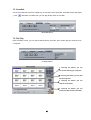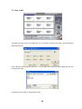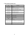
1
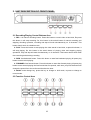
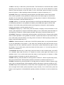
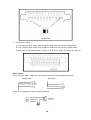
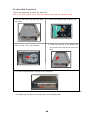
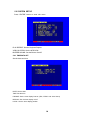
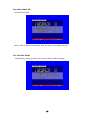
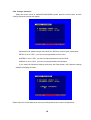
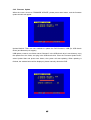
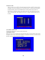
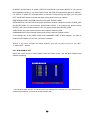
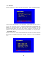
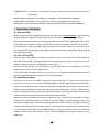
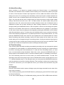
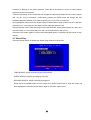
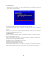
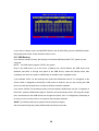
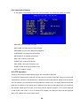
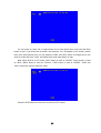
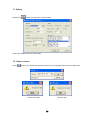
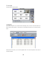
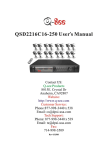
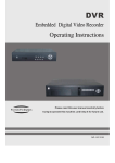
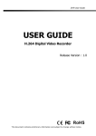
Safety Precautions
The lightning flash with arrowhead symbol, within an equilateral
triangle, is intended to alert the user to the presence of insulated
dangerous Voltage within the product’s enclosure that may be
sufficient magnitude to constitute risk of electrical shock to persons.
The exclamation point within an equilateral triangle is intended to
alert the user to the presence of important operation and
maintenance (servicing) instructions in the literature accompanying
the appliance.
Attention: installation should be performed by qualified service
Personnel only in accordance with the National Electrical Code or
applicable local codes.
Power Disconnect. Units with or without ON-OFF switches have
power supplied to the unit whenever the power cord is inserted into
the power source; however, the unit is operational only when the
ON-OFF switch is the ON position. The power cord is the main
power disconnect for all unites.
CAUTION: Danger of explosion if battery is incorrectly replaced.
Replace only with the same or equivalent type recommended by the
manufacturer. Dispose of used batteries according to the
manufacturer’s instruction.
Warranty
and Service
During the warranty period (one year for Hard Disk), we will repair or
replace the hard disk free of charge.
Be sure to have the model number, serial number and vendor stick
on hard disk for service representative.
About this document
Before installing stand alone DVR, be sure to thoroughly review and follow the instructions in
this Users Manual. Pay particular attention to the parts that are marked NOTICE.
Also, when connecting with external application, first turn the power OFF and follow manual
instruction for appropriate installation.
2
Before reading this document
1. This document is intended for both the administrator and users of this stand alone DVR
Model.
2.This manual contains information for configuring, managing and using this stand alone DVR
Model.
3. To prevent fire or electrical shock, do not expose the product to heat or moisture.
4. Be sure to read this manual before using this stand alone DVR Model.
5. For questions and technical assistance of this product, contact Q-see.
►Strong recommendation on installation of the DVR unit
1. Verify that the electricity at the place you want to install the DVR unit is stable and meets
our electrical requirements.
Unstable electricity can cause malfunction of the unit or cause critical damage to the unit.
Notice: We also STRONGY recommend that you plug the DVR and cameras into a
Transient Voltage Surge Protector (UL-1449 rating). Look for a clamping voltage of
330 or lower, Joule rating of at least 400, and a response time of 10 nanoseconds or
less.
2. Several chips on the main board of the DVR unit and hard drive inside the unit generate
heat and it must be properly discharged.
Do not put any objects near the exhaust port (fan) on the left side of the unit and do not
block the opening (fresh air in-take) on the right side of the unit..
3. Put the DVR unit in a well-ventilated place and do not put heat-generating objects on the
unit. When it is installed inside 19 inch mounting racks together with other devices check
that the built-in ventilation fan of the rack is properly running.
3
CONTENTS
1. FEATURES AND FUNCTION…………………………………………………………………….…..5
2. UNIT DESCRIPTION OF FRONT PANEL.…………………………………………………..……….6
3. REAR PANEL AND SYSTEM CONNECTION…..……………………………………………………8
4. REMOTE CONTROL…………………………………………………………………………………12
5. SYSTEM SETUP………………….………………………………………………..………………..12
5.1. SETUP MENU.………………..…………………………………………………………………12
5.2. SYSTEM SETUP…………………………………………………………………………………14
5.2.1. TIME/DATE SET……………………………………………………………………………...14
5.2.2. HDD FORMAT SET…………………………………………………………………………15
5.2.3. FACTORY RESET………………………………………………………………………….15
5.2.4 CHANGE PASSWORD………………………………………………………………………16
5.2.5 FIRMWARE UPDATE…………………………………………………………………………17
5.3. DISPLAY SETUP………………………………………………………………………..………18
5.3.1. CAMERA NAME SET…………………………………………………………………..……18
5.3.2. COLOR SET.……………………………………………………………………………..…19
5.3.3. AUTO SEQUENCE SET…………...………………………………………………………20
5.4. RECORD SETUP………………………………………………………………………………….20
5.4.1. AUDIO CH SET………………………………………………………………………………21
5.4.2. REC CH SET.……………………………………………………………………………..…22
5.4.3. RECORD LENGTH SET………………………………………………………………..…22
5.5. NETWORK SETUP.……………………………………………………………………………….22
5.5.1. N/W ENABLE SET……………………………………………………………………………23
5.5.2. MAC SET……………………………………………………………………………………24
5.6. SENSOR SETUP…………………………………………………………………………………24
5.6.1. MOTION DETECTION SETTINGS…………………………………………………………25
5.6.2. MOTION AREA SET…………………………………………………………………………26
5.7. SCHEDULE SET…………………………………………………………………………………27
5.8. USB BACKUP……………………………………………………………………………………27
5.9. STORAGE INFO…………………………………………………………………………………28
5.10. PTZ SET…………………………………………………………………………………………28
6. QUICK USER GUIDELINE……………………………………………………………………………29
7. USING THE NETWORK VIEWER……………………………………………………………………38
8. MAIN STANDARD & PARAMETER CHART……………........…………………………………44
9. TROUBLE SHOOTING GUIDE……………........……………........………………………………45
10. RECORD TIME TABLE……………...……......……………........…………………………………47
11. INTERNET VIEW/PLAYBACK CONFIGURATIONS………........………………………………48
Q-SEE PRODUCT WARRANTY…………………………………………………………………...51
4
1. FEATURE AND FUNCTION
l
Video input: 16channels; Video output: 3channels.
l
Audio input: 4channels; Audio output: 2channels.
l
16 alarm input and 1 relay alarm output.
l
Compression mode: M-JEPG.
l
Support network view.
l
Support USB backup.
l
Compatible with NTSC and PAL format.
l
Support zoom, auto function, watermark security.
l
Four optional levels of image quality: very high, high, low, very low. Record and play-back
frame rate are changeable.
l
Support alarm recording, time recording.
l
Support video loss and motion detection functions.
l
Multi-function searches: be able to distinguish different alarm records and time records from
ordinary records; be able to search by time, by segment or by event.
l
Support various playback modes: pause, several fast forward and backward play modes.
l
Equipped with remote device and PTZ control enables (RS485).
l
Triplex operation can play back and search while it is recording.
l
480frame (NTSC, PAL is 400) per second for view, 120frame (NTSC, PAL is 100) per
second for recording.
l
SATA Hard Disk Interface, support Over 500G Byte.
5
2. UNIT DESCRIPTION OF FRONT PANEL
2.1 Recording/Playing Control Buttons Area
1. REC: It is manual recording button. Press this button to record video to hard disk, Re-press
this button, it will stop recording. So, this button is the switch button of manual recording and
stopping recording operation, recording and stop will work simultaneously on 16 channels. This
button doesn’t work in schedule mode.
2. PLAY: Press this button to start playing the video stored in hard disk, re-press this button, it
will stop playing. So, this button is the switch button of playing video and stopping playing
operations. Play and stop will work simultaneously on 16 channels. This button doesn’t work while
time recording and alarming recording.
3. REW: fast backward button. Press this button to start fast backward playing till press play
button to start normal playing.
4. FORWARD: fast forward button. Press this button to start fast forward playing till press play
button to start normal playing the fast forward has five speeds; each time you press the button will
change the speed from slow to fast and then back to slow.
5. MODE: mode change key, press this key to change to shift mode, re-press to change to
normal mode.
2.2 Function Control Area
6
1. Auto/1: Auto key, in shift mode, press this button, The DVR will be in auto dwell state, it dwells
according to the time set in auto sequence set menu, and you can set the dwell time of each
channel. Press this button to quit this mode. If not in shift mode, press this button to see big
picture of channel 1. While inputting numbers, this button is used as number key of “1”.
2. Zoom/2: Zoom key, in shift mode, press this button, the DVR will be in zoom mode, please
refer to zoom operation in user guideline for details, press zoom button again to cancel zoom
operation. If not in shift mode, press this button to see big picture of channel 2. While inputting
numbers, this button is used as number key of “2”.
3. USB/3: USB key, in shift mode, press this button, the DVR will start USB backup, please refer
to USB backup operation in user guideline for details, press USB button again to cancel USB
backup. If not in shift mode, press this button to see big picture of channel 3, while inputting
numbers, this button is used as number key of “3”.
4. Display/4: Display key, in shift mode, press this button to display current information on the
screen, press again this to clear the information display. If not in shift mode, press this button to
see big picture of channel 4. While inputting numbers, this button is used as number key of “4”
5. Freeze/5: Freeze key, in shift mode, press this button, the DVR will be in freeze mode, please
refer to freeze operation in user guideline for details, re-press this button to quit freeze mode, If
not in shift mode, press this button to see big picture of channel 5. While inputting numbers, this
button is used as number key of “5”.
6.WM/10+: Watermark button, In shift mode, if the DVR is playing video, you can press this button
to see the watermark of the picture, if the video was recorded by this DVR and has not be
changed, there will be a watermark symbol in each picture, press watermark key again to clear
the display. If not in shift mode, press this button and then press 1 to 6 to see big picture of
channel 11 to channel 16.
7. Schedule/6: Schedule key, in shift mode, press this button to enter schedule state, if the DVR
is in schedule state, there will be an “S” symbol on screen, press again this button to quit
schedule mode. If not in shift mode, press this button to see big picture of channel 6. While
inputting numbers, this button is used as number key of”6”
8. ADD/7: Add key, press this button to see big picture of channel 7. When in system setup menu,
this is an increase button. While inputting numbers, this button is used as number key of “7”.
9. DEC/8: Decrease key, press this button to see big picture of channel 8. When in system setup
menu, this is a decrease button. While inputting numbers, this button is used as number key of”8”.
10. SR/9: Single frame rewind button, in shift mode, while in playback state, long press this button
can see single frame rewind, press play button to play normally. If not in shift mode, press this
button to see big picture of channel8.while inputting numbers, this button is used as number key
of”9”.
7
11. SF/0: Single frame forward button, in shift mode, while in playback state, long press this
button can see single frame forward, press play button to play normally. If not in shift mode, press
this button to see big picture of channel 10.while inputting numbers, this button is used as number
key of”0”.
12. Search/Menu: press this button to enter search menu, please refer search play in user
guideline for details. Long press this key to enter menu (need password), in menu setup, press
this key to quit current menu.
2.3 Channel Choosing Control Area
1. Nine pictures/left: Press this button to see nine pictures
display, re-press this button to see eight pictures. While
select menu items, press this button to move the cursor left
ward.
2. Sixteen picture/right: Press this button to see sixteen
pictures display, re-press this button to see thirteen
pictures. While selecting menu items, press this button to
move the cursor rightward.
3. Big picture/up: Press this button to see full screen, repress this button to see the next channel. While selecting
menu items, press this button to move up the cursor.
4. Four pictures/down: Press this button to see four pictures display, re-press this button will
display next four pictures. While selecting menu items, press this button to move down the cursor.
5. Enter: While selecting menu items, press this button to select the item. While playing video,
press this button to pause the play, press play button to continue play.
3. REAR PANEL AND SYSTEM CONNECTION
8
3.1 Back panel and connection terminals
The power cable and input, output signal terminals are all at the back of the machine, the
connection to monitor, camera etc equipments are all carried out through the terminals and
sockets on the back panel the back view of the machine is illustrated as below.
Each part of the back panel is illustrated as below:
1. Video input CH1-CH16 2.main output 3.assistant monitor 4.S-VIDEO 5.audio input 6.audio
output 7.net interface 8.USB port 9.power 10.debug port 11.Alarm and RS485 ,port define:
(1-12: sensor1-sensor12; 13, 20, 24, 25: GND, 14-17: sensor 13-sensor16, 18: RS485A 19:
RS485B, 21: COM 22: NC 23: NO)
3.2 Video and Audio Connection
The DVR can support up to 16 cameras video input at the same time.
Main
Out
Video In 1
CH1
Assisant S Video
Out
Out
Video In 16
CH2
CH3
CH4
CH5
CH6
CH7
CH8
IN
OUT
1
2
OUT
CH9
CH10
CH11
CH12
CH13
CH14
CH15
CH16
OUT S VIDEO 3
4
AUDIO
Microphone
The DVR can connect 4 channel’s audio input, but you can only select one for recording. To
display the DVR picture, the DVR video output signal should be transferred to your TV set or
monitor. Any TV set that has a “video input” terminal is suitable for displaying the image. The
figure above shows the video and audio signal line connection.
Notice: you can only connect one audio input at any one time, which means, if you
connect an audio input to CH1, you cannot connect any to CH2 through CH4.
3.3 Alarm Connection
The DVR can support up to 16-alarm input and 1 alarm output.
Alarm input: there are two types of alarm input.
1. Voltage output (5V and 0V)
A: In case sensor output high voltage (5V) normally and output low voltage when trigg
ered (0V), then users must set DVR as low voltage alarm.
B: In case sensor output low voltage (0V) normally and output high voltage when trigg
ered (5V), then users must set DVR as high voltage alarm.
Please refer to the picture below, channel 2 to channel 16 are the same as channel 1.
9
2. Open/Close output
A: N.O. Normal open, close when triggered. DVR must set as low voltage alarm.
B: N.C. Normal close, open when triggered. DVR must set as high voltage alarm.
Please refer to the picture below, channel 2 to channel 16 are the same as channel 1.
Alarm output:
There are three alarm output pin, the status of these pin are illustrated as below
Before Alarm
After Alarm
There is an example for alarm output connection
10
3.4 Hard Disk Connection
There are processing to install the hard disk.
Note: If the DVR comes with a HDD pre-installed then skip the following steps.
1. Pull out the hard drive rack from DVR
2. Connect the DATA cable & power cord.
side panel.
3. Open the top cover of the drawer.
4. Close the top cover of the drawer and
put the hard drive drawer back into the
DVR
5. Lock the hard drive draw by turning the key clockwise.
If you have another HDD, please jump that HDD to SLAVE, and open then machine, put the HDD
to the HDD rack, and then connect the power cord and DATA cable.
11
4. REMOTE CONTROLLER
0 – 9, 10+: Select the channel (Full screen)
2x2: 2x2 Screen Modes
3x3: 3x3 Screen Modes
4x4: 4x4 Screen Modes
USB: USB Storage Backup
AUTO: Auto Sequence Mode
ZOOM: 2X Zoom
FREEZE: Freeze
DISPLAY: Hard Disk Information
MENU/EXIT: System Setup
SEARCH: Time Search, Event Search and Start Stop Search
ENTER: Enter Next Menu
REC: Record
WM: Watermark set
PTZ: Control Speed dome
5. SYSTEM SETUP
Before using the video recorder, the first step is to set up the system according to user’s needs;
otherwise the machine will run with the default settings.
5.1 SETUP MENU
When in setup mode, press upward button or downward button, the cursor will move among
the settable items, continuous pressing will make the cursor move among the options one by
one, and it can recur. The selected one will display in yellow color.
While choosing digital fields, e.g. year, month, day, hour, minute, second etc, press
leftward button or rightward button, the cursor can move leftward or rightward among
The several digits of one field, continuous pressing will make it move among digits one by one,
and it can recur.
Please press leftward or rightward button to change the value that the cursor on,
Press “ENTER” button to enter sub menu and press menu button to return to previous menu.
Long press the menu/search button on the keyboard or press the remote controller to enter the
Setup Main Menu. You can show password input box according setting of password set. If you
fault password input 3-times, then you can’t enter the setup menu. Default password is “0000”,
12
If you enter the correct password, the main menu will display ad below.
13
5.2 SYSTEM SETUP
Press “ENTER” button to enter sub menu
PLAY REPEAT: Set the Playback Repeat
VIDEO SYSTEM: Set the NTSC/PAL
BUZZER SOUND: Set the Buzzer On/Off
5.2.1 TIME/DATA SET
Set the date and time.
DATE: Set the date
TIME: Set the time
FORMAT: Set the time display format (USA, EURO and Asia Users)
DISPLAY: Set the time display on/off
LOCAL: Set the time display position
14
5.2.2 HDD FORMAT SET
Format the hard disk.
Select “YES”, to format the hard disk. And all video on the HDD will loss.
5.2.3 FACTORY RESET
Initialize all the setup; the DVR will reset to factory default settings.
15
5.2.4 Change Password
When the cursor moves to CHANGE PASSWORD, please press the enter button, and the
Change Password window will appear.
Password Level: password type of the DVR, the DVR has various types of password:
SETUP: If set to “YES”, you have to input password to enter menu.
SYSTEM: If set to “YES”, you have to input password to boot the DVR.
ALWAYS: If set to “YES”, you have to input password to all operation.
If you select the Password Change and press the Enter button, the Password change
window will display as below:
Please enter the current password, then input new password and confirm the password.
16
5.2.5 Firmware Update
When the cursor moves to FIRMWARE UPDATE, please press enter button, and the firmware
update window will appear.
Update Method: There are two methods to update the DVR firmware, USB (for USB thumb
drives) and Network (not support)
USB update: create a new folder named “firmware” in the USB thumb drive’s root directory, copy
the update file to the folder, and plug in the USB thumb drive. Enter the Firmware Update menu,
select Update Start and press enter button, the system will start updating. When updating is
finished, the window below will be displayed, please manually reboot the DVR.
17
5.3 DISPLAY SETUP
BOUND COLOR: Set the Color of Video Boundary (BLACK / WHITE / GRAY).
BLANK COLOR: Set the Background Color of Loss Video (BLACK / WHITE).
5.3.1 CAMERA NAME SET
When the cursor moves to Camera Name, please press the Enter button, the Camera Name
Setup window will appear.
Press the up or down button to select channels, press the Enter button to change the channel
name.
18
Each channel’s name is a combination of six eight characters. Press up or down button to
select each character, press LEFT or RIGHT button to modify each character, and then press
enter button to save this name.
DISPLAY: if Display is set to “OFF”, the channel’s name will not display on the screen.
5.3.2 COLOR SET
When the cursor moves to Color Set, please press the Enter button, the Color Setup window
will appear.
CON: picture contrast
BRI: picture brightness
HUE: picture hue
SAT: picture saturation
Press LEFT or RIGHT button to select CON/BRI/HUE/SAT, press UP or DOWN button to
change the value, if setup over, press UP or DOWN button to change channel.
19
5.3.3. AUTO SEQUENCE SET
When the cursor moves to Autoseq Set, please press enter button, the Auto Sequence Setup
window will appear.
Press the UP or DOWN button to select channel, press LEFT or RIGHT button to change the auto
Sequence time.
5.4 RECORD SETUP
When the cursor moves to Record Set, then press the Enter button, the Record Setup window will
appear, which is illustrated as below. Press UP or DOWN button to move the cursor. Then press
the LEFT or RIGHT button to change the value. While the DVR is in recording or playback mode,
you cannot access this menu unless you stop record or play first.
OVER WRITE: if set to “YES”, the DVR will automatically overwrite the HDD from the
beginning when the HDD is full. If set to “NO”, the DVR will automatically stop recording when
the HDD is full. If there are two HDD in the DVR, when the MASTER HDD is full, the video
will store to the SLAVE HDD, and when the SLAVE HDD is also full, the DVR will overwrite
the MASTER HDD if set this to “YES”, otherwise it will stop recording.
20
REC SPEED: the recording frame rate of the DVR, factory default setting is 30F/SEC under
NTSC (25F/SEC under PAL). This means the DVR records the events at the speed of 30
shots of frames per second. The higher of the record frame rate, the more natural look will be
displayed on the screen when you playback the footage. The lower of the record frame rate,
the more you can save the space on the hard disk. The highest frame rate is 120F/SEC(PAL
is 100F/SEC) when the resolution is in CIF mode
REC QUALITY: There are four different video quality settings: LOW, LOW+, HIGH, HIGH+.
The higher of the video quality, the clearer images you can get when you playback. The lower
of the video quality, the more you can save the space on the hard disk drive.
RESOLUTION: the record picture size of the DVR have two modes:CIF and FIELD, default is
CIF. In FIELD mode, the recorded picture is twice the size of that in CIF mode. In CIF mode
the REC speed is 120F/SEC NTSC (PAL is 100F/SEC) and the maximal REC speed in
FIELD mode is 60F/SEC NSTC (PAL is 50F/SEC).
PB SPEED: the frame rate of playback, default is AUTO, which means the same as record.
5.4.1 AUDIO CH SET
When the cursor moves to Audio CH Set, press the Enter button, the Audio CH Set window
will appear, as illustrated below.
There are four audio input channels, for each channel you can select anyone of the 8
channels. Although there are four audio input channels, you can only record from one
channel’s audio at the same time. To setting the audio correctly, you have to select one
channel within these four channels in the Audio Select menu.
21
5.4.2 REC CH SET
When the cursor moves to REC ch Set, please press enter button, the REC ch setup window
will appear. This screen is different for CIF and FIELD modes . In FIELD mode, the window is
illustrated as below, press UP and DOWN buttons to select channel and press LEFT or
RIGHT button to change the setting, if the channel is set “OFF”, this channel will not record
when in recording mode. If the resolution is set to "CIF ", the REC ch Setup window can not
be setup.
5.4.3 RECORD LENGTH SET
To set the file package time in continuous time record mode
5.5 NETWORK SETUP
When the cursor moves to Network Set, press the Enter button, and the network setup window
will appear. Please note if the Netviewer software is connected to the DVR. You cannot access
this menu unless you close the Netviewer software.
22
IP MODE: the DVR has 2 IP modes, STATIC IP and DHCP, if you select STATIC IP, you can set
the IP address manually, if you select DHCP mode, the DVR will automatically get the IP address.
For STATIC IP, press UP or DOWN button to move the cursor among the digits, you can press
LEFT and RIGHT buttons to modify the digits, press enter to save you change.
WEB SERVER PORT: the WEB transmit port for data. Default is 0080.
NETWORK ENV: the DVR has three types of different network conditions: LOCAL, EXTER_LAN,
and EXTER_WAN. If in local network, please select LOCAL. If for internet use, please choose
EXTER_LAN. If the internet condition is not very good, please select EXTER_WAN.
VIDEO PORT: the video transmit port for the computer. Default is 5000.
COMMAND PORT: the command transmit port for the computer. Default is 5001.
If you change any of the VIDEO PORT and COMMAND PORT or MAC address, you have to
restart the DVR before you use the “net viewer” software.
Notice: if you have changed the MAC address, you will not have access to the “MA
C ADDR SET” Option.
5.5.1. N/W ENABLE SET
When the cursor moves to N/W Enable, press the Enter button, and the N/W Enable setup
window will appear.
If one channel here set OFF, this channel will not transmit to the network, so if you want to see a
channel from network, you must to set this channel ON.
23
5.5.2. MAC SET
When the cursor moves to Mac Set then press the Enter button, the Mac Set window will appear.
If you have more than one DVR in a local area network, you have to set each DVR to have an
exclusive MAC address, but remember that you have only one chance to modify the MAC
address, once you have changed the MAC address, this menu will not appear again. If you want
to change the MAC address again, please load the factory set, then you can change the MAC
address. For MAC address, you’d better set the first two bytes to “00 00”, and change other bytes.
5.6 SENSOR SETUP
When the cursor moves to Sensor Set, then press the Enter button, the sensor setup window will
appear. Press UP or DOWN button to move the cursor. Press LEFT or RIGHT to change the
value.
24
ALARM ENABLE: alarm trigger switch, can be set to off, N.C(normal closed) or N.O(normal open).
If users set it to off, the DVR will ignore the alarm input.
MOTION ENABLE: Motion alarm switch, can be set to ON or OFF. If set to off, the DVR will ignore
the motion alarm.
MOTION LEVEL: motion sensitivity level, if the figure in the picture is small, please set to high or
very high, default is normal.
BUZZER TIME: buzzer sound time when there is a sensor or motion alarm.
SENSE RECTIME: when a motion or sensor alarm is triggered, the recording time of DVR, default
is 10 seconds.
Notice: Users should press the schedule button after setting up the parameters to activate
the settings.
5.6.1 Motion Detection settings
1) When surveying nearby objects (2-10 meters)
When in daytime, please set motion detection sensitivity to Normal level; when in night,
please set to low.
2) When surveying objects in 50-100 meters area
The objects 50-100 meters away will be quite small on the screen. When in daytime, please
set motion detection sensitivity to high level.
25
When in night as below, please set to normal level.
Note: the above suggestions are a guide only based on testing in a general environment. You
will need to select the best parameters according to the actual operation environment you are
covering. Try different settings until you get the desired motion detection result.
5.6.2 MOTION AREA SET
Move the cursor to Motion Area Set, then press the Enter button, and the area setup window
will appear. Press the up, down, left, right button to move the cursor and press the Enter
button to change from detection ON to OFF. Press and hold the Enter button to change all
values to the same as the area you have selection.
If the area marker icon is set to yellow, this area is monitored for motion detection, and if the
icon is blue, motion sensing is disabled for that area.
26
5.7 SCHEDULE SET
When the cursor moves to Schedule Set, press the Enter button, and the schedule setup
window will appear.
You can change a recording schedule during a day by using this setup window.
Please note: Military time must be used.
START: start record time
STOP: stop record time
SCHEDULE ENABLE: must set to “on”, if want to enable schedule record function
Note: Manual record mode and schedule record mode (including motion detection
record mode, sensor record mode and time schedule record mode) can not be used at
the same time. Once the user selects Schedule record mode, manual record mode will
disabled; once user select manual record mode, schedule record mode will be
disabled.
5.8 USB BACKUP
Set the USB BACKUP.
Plug in the USB device, and press “ENTER” button, you can see the below picture.
There are two types of backup mode: STILL and MOVIE, in STILL mode you can backup Picture
and in MOVIE mode you can backup video.
27
5.9 STORAGE INFO
When the cursor moves to Storage Info, press the Enter button, and the storage info window
will appear.
MODEL: Model Number of the Hard Disk
CAPACITY: Total capacity
USED SIZE: Space used
OVER WRITE: The number of times overwritten
5.10 PTZ SET
When the cursor moves to PTZ Set, press the Enter button, and the PTZ Set window will appear.
You must set the correct protocol so you can control a Pan Tilt camera (Speed Dome) via the
DVR. Press the UP or DOWN button to move the cursor, and press LEFT or RIGHT to change
the value.
28
CHANNEL SEL: If you have a speed dome camera, select the channel which the camera is
connected to.
BAUD RATE: Changeable from 1200bps to 115200bps. The default value is 2400bps.
DOME ADDR: The address of the speed dome camera, changeable from 0x00 to 0xff.
PROTOCOL: The protocol of speed dome camera: PELCO-D,PELCO-P,NEON,SAMSUNG
6. Quick User Guideline
6.1 Start the DVR
Before starting the DVR, please make sure all the items in the “Security Notice” at the beginning
of this manual are fulfilled and that the input and output cables are all correctly connected.
Also ensure the DVR’s video input format (NTSC/PAL) and the monitor (NTSC/PAL) are both set
to the same video standard. NTSC for USA & Canada, PAL for Australia, UK and most of Europe.
Fit the hard disk to the removable caddy and insert the removable caddy into the housing, then
lock it up (turn the hard disk lock to the right) and connect the power which will then boot the DVR
and it will start to work.
6.2 Turn off the DVR
Only turn off the DVR when the system is inactive. Do not to turn off the DVR while playing or
doing the System Setup. Turning off the DVR while recording may cause the recording to corrupt,
and can cause the HDD to be unreadable in some cases.
Press the Record button to stop recording or press Stop button to stop playing or exit from
System Setup menu, then turn off the power.
If do not wish use the video recorder for a long time, you should pull out the power line from the
electrical outlet and store the unit where it will not be damaged.
6.3 Normal Recording
Connect the power to all related equipment; ensure that there is video input using direct
connection to your TV or VCR. Press the Display button to check spare space of the hard disk, if
there is not much space, please consider changing your hard disk first or select Overwrite mode.
Check recording parameter setup before recording; select video quality, frame rate. Note that you
cannot change record setting during the process of recording. Manual recordings are the normal
recording condition. Under the manual mode (non-schedule status),
pressing the Record button will record all channel’s video. Press the Record button to begin
recording, four channels will start simultaneous recording. While in normal recording mode, press
the Record or Stop button, and enter the right password, to stop recording. During the process of
recording if the hard disk is full and the system is set to automatic overwrite, the recording will not
be interrupted but the DVR will automatically begin to overwrite recorded video from the earliest
(oldest) recorded area. If the system is set to overwrite disabled, it will stop recording once the
HDD is full.
29
6.4 Alarm Recording
Alarm recording is not started by manually pressing the Record button, it is automatically
activated once Schedule mode is enabled. Alarm recording can be activated by alarm input signal
or motion, if the connection of alarm input equipment is correct, stable and reliable, and the alarm
settings are correct. For recording to be activated by exterior input signal or motion detection the
system must be set to Schedule Mode active and that period is set to “A” in Record Schedule
setup. You must also set the menu of Alarm Setup for exterior input alarm, and the alarm enable
setting of that channel must be set to “ON”. For Motion Alarm, the motion enable setting of that
channel must set “ON”, and set the area for motion detection must be set. If Schedule mode is
disabled the system will not start recording on alarm. Setting schedule on or off is achieved
through pressing the SCHEDULE button on the front panel or remote, but not through the System
Setup menu and window. When the unit is in Schedule Mode active, the character “S” will display
on the screen. Alarm video recording can’t be stopped by pressing the RECORD or STOP button
while Schedule Mode is active. To ensure that once Schedule Mode is set to on that the schedule
cannot be accidentally stopped there is a password protection to stop Schedule Mode. You must
press the SCHEDULE button then enter the correct password to turn Schedule Mode off. Check
Alarm Recording setup before recording; confirm the video quality and the frame rate, as the
record setting can’t be changed during the recording process. As long as the alarm input signal is
correctly set the alarm recording will continue during the period of time set up by A/M REC TIME,
and when the outside the time period the alarm recording automatically stops.
6.5 Time Recording
Time recording starts and stops recording automatically according to the pre-arranged time period.
It is applied to a fixed timetable, for example business hours time recording (or outside business
hours time recording) with fixed start/stop time. To start the Time Recording function you must
have a record schedule setup beforehand. When this is done, press the SCHEDULE button on
the front panel to set schedule mode to on and the schedule symbol “S” will display on the screen.
The Time Recording mode will not work unless you activate Schedule Mode. To make Time
Recording mode active the system must be set to Schedule Mode active and that period is set to
“T” in Record Schedule setup. In Time Record mode, you must press the SCHEDULE button then
enter the password to stop time recording. Because Time recording is reliant on the system being
set with the correct time, you must adjust the time to your correct local time before using this
function.
6.6 Playback
Press the PLAY button and the system will begin to play the images recorded from the start of the
most current recording.
If the recording is playing, press the PAUSE button to pause playing, press the PLAY button again
to resume normal play.
To use Fast Forward playing or Fast Backward playing, press the FWD or REW button while the
30
recording is playing to see faster playback. Press the PLAY button to return to normal speed
playing from the current place.
Continuous pressing of the FWD button will change the fast-forward between four levels of speed
(X2, X4, X8, X16,) in sequence. Continuously pressing the REW button will change the fast
backward playback between four levels of speed (X2, X4, X8, X16) in sequence.
During playback mode, press the Single Frame Forward button to play a frame at a time, and hold
the button in to continually play one frame at time while the button is hold.
During playback mode, press the Single Frame Rewind button to play back a frame at a time, and
hold the button in to continually play one frame at time while the button is hold.
Press the PLAY button again to resume normal playback speed, or press the STOP button to stop
playing.
6.7 Search Play
Press the search button to display the Search play window on the screen.
TIME SEARCH: search recording by the time entered.
EVENT SEARCH: search recording by event list.
RECORD SEARCH: search recording by segment.
Press the UP or DOWN button to move cursor, then press Enter button to enter sub menu you
have highlighted. Press the Search button again to quit from search menu.
31
6.8 Time Search
Move the cursor to Time Search, then press the Enter button and the Time search window will
appear, which is illustrated as below.
The red block below the number means there is recorded video at that time.
Press the LEFT and RIGHT buttons to move the cursor along the year, month, day, hour and
minutes.
Please note: You can only view footage that has been recorded. Therefore you must select time
and dates that have a red block below them.
6.9 Event Search
Move the cursor to Event Search, and then press the Enter button, the event search window will
appear, which is illustrated as below.
There are four types of event on this list: MOTION, ALARM, SCHEDULE and NETWORK.
MOTION means motion triggered alarm recording.
ALARM means external sensor triggered alarm recording.
SCHEDULE means scheduled time recording.
NETWORK means network activated recording.
Press the UP and DOWN buttons to move the cursor along the event list, and press the Enter
button to play the segment you selected. Press the search button to return to the Search menu.
32
If you want to search from MASTER HDD to SLAVE HDD, press the SERACH button, and then
press Enter button. Press the Menu button to exit.
6.10 Record Search
Move the cursor to the Record Search, press the Enter button, and the record search window will
appear, which is illustrated as below.
All recorded segments are displayed here, press the up or down button to move
the cursor along the segment list, press left or right buttons to see previous or next
page, press the Enter button to play the segment you selected. Press search
button again to return to the Search Play menu.
33
If you want to change it from the MASTER HDD to the SLAVE HDD, press the SEARCH button,
then press Enter button. Press the Menu button to exit.
6.11 USB Backup
If you want to use this function, the first step is to format USB device with “FAT” system on your
computer.
NOTE: the DVR doesn’t support “FAT32” file system.
Plug in the USB device, go to the menu of Backup set, check whether the USB device was
detected, and there is enough free space of the USB device, select the backup mode, then
completely exit the menu system. USB backup is available only in playback mode.
If you selected “STILL” for the backup mode, press the USB button and an “S” will appear on the
screen. When it disappears, the backup of the picture is finished, and you can un-plug the USB
device out and see the picture on a computer with the netviewer software.
If you select “MOVIE” for the backup mode, press and hold the USB button until the “A” appears on
the screen, press the USB button again to select the end of the backup video. This may take a little
time, and make sure the USB device has enough free space, if the “A” disappears, the backup is
ok, and you can view the video on a computer with netviewer software.
NOTE: if you backup still picture, please choose full picture display.
We recommend using high quality USB thumb drives that we provide
34
6.12 USB Update
Using your PC to create a folder called “firmware” in the root directory of your USB memory stick,
copy the update files to the folder. Plug the USB device into the DVR, go to the menu of Backup
set, check that whether the USB device was detected, go to the Firmware Update menu and
select USB method, move to Update Start and press Enter button and the update will start. If you
see screen below, update was successful. Then reboot the DVR.
NOTE: Do not shut down the DVR when the DVR is updating, it may damage the system.
6.13 Zoom Operation
In shift mode, press zoom button, the DVR will be in zoom mode, which is illustrated as below.
Press upward, downward, leftward or rightward to move the zoom area, and then press enter
button to zoom, press zoom button again to cancel zoom operation.
35
6.14 Information Display
In shift mode, press display button, the main information of the DVR will display on screen.
HDD SIZE: the size of the hard disk
HDD USED: the used space of the hard disk.
HDD READ: current HDD address for playback
OVERWRITE: overwrite time of the HDD
NETWORK IP: IP address of the DVR.
REC LIST: number of record list
EVENT LIST: number of event list
REC OVER: record list overwrite or not
EVENT OVER: event list overwrite or not.
S/W VER: software version
6.15 PTZ Operation
This DVR can control all speed domes which are connected to the DVR.
To control the speed dome, make sure all the lines are correctly connected, first you must set the
right protocol, baud rate, and speed dome’s address for each speed dome, please refer to protocol
set. For example, you connect the first speed dome to channel one, you should make sure that the
baud rate, the protocol, and speed dome’s address is the same as the speed dome you connect to
the channel. Press the PTZ button on the front panel or remote controller, “PTZ” will be displayed
on the screen, then select 1 to 16 to choose PTZ channel, the channel number will be displayed
after “PTZ”, please refer to the picture below:
36
You can press up, down, left, or right buttons to move the speed dome, and press the Enter
button to stop. If you press the Iris button, the character “Iris” will appear on the screen, please
refer to the picture below, then you can press the “ADD” and “DEC” button to change the Iris, the
same to control the focus, zoom, and speed, also press enter button to stop.
Note: When DVR is in PTZ mode, “REC” button is used as “ZOOM”; “PLAY” button is used
as “IRIS”; “REW” button is used as “FOCUS”; “FWD” button is used as “SPEED”. “ADD” and
“DEC” buttons are used to adjust the value.
Press the PTZ button one more time to exit from PTZ control.
37
6.16 REMOTE CONTROLLER
REC: Start or stop recording
SCHEDULE: Start Schedule recording function
0~9: Select channel or input password
2x2: Display Quad mode on screen
3x3: Display 9-channel cameras on screen
4x4: Display all 16-channel cameras on screen
AUTO: Same with “Auto” button on DVR keyboard
DISPLAY: Same with “Display” button on DVR keyboard
MENU: Same with “MENU” button on DVR keyboard
W/M: Same with “W/M” button on DVR keyboard
SEARCH: Same with “Search” button on DVR keyboard
CH +-: Change channel
SET+-: Select channel, address, or speed while in PTZ function
Forward button
Backward button
: Move one frame picture forward in Pause mode
: Move one frame picture backward in Pause mode
ZOOM: Same with “Zoom” button on DVR keyboard
FREEZE: Same with “Freeze” button on DVR keyboard
7. USING THE NETWORK VIEWER
Using the net viewer software, you can view the DVR through Internet or Intranet, also, you can view
and backup the video data on the HDD through a computer. Open the software; you will see the
window below:
38
7.1 Setting
Please click
button, you will see the window below:
Enter the IP address and click “OK” button.
7.2 Viewer connect
Press
bottom, you can see the login box. Enter the correct password and click ok to login DVR.
<Connect success>
<Connect fail >
39
7.3 Live play
Click play button to see live picture,
7.4 Playback
After clicking “Playback” tab, net search window will display. First, you have to select the HDD of the
DVR. Click the “Get record list” or “Get event list”, if the DVR has record list, you can see the window
below:
Double click the record list; you can see the playback video. The event list operation is the same as
record list operation.
40
7.5 Scandisk
Connect the HDD that used in the DVR to a PC and then select Scandisk, Scandisk window will displa
y, click
and select one HDD, then you can play all the video on the HDD.
<Scandisk Menu>
7.6 File Play
Press “FilePlay” button, you can see the below picture, press the “open” button play the video file on th
e computer.
< Fileplay Menu>
1. Pressing the button, you can
record the video by you computer.
2. Pressing the button, you can See
the below picture.
3. Pressing the button, you can
stop the record DVR.
4. Pressing the button, you can
remote the DVR record to the HDD.
41
7.7 Save to AVI
To record the video to your PC’s HDD with “.avi” file system, just click" AVI" button, and the following
window will pop-up
Here, select the record channel and click "+" icon to define the file name and save path and click "ok"
to start the AVI save.
Re-press the "AVI" button to stop the AVI record.
42
7.8 Save to DVR
To record the video stream to your PC’s HDD , just click" DVR" button and the video stream will be
saved in the directory that you set (the default directory is c:\DVR\)
Note: to play the file saved to DVR, just click "FilePlay" tab to open it.
7.9 PTZ Control
To control the speed dome, just click "UP","DOWN","LEFT" and "RIGHT" buttons to control speed
dome's horizontal or vertical position. Also, you can control speed dome's Iris, Focus and Zoom , just
to select the item and then click the "+" and "-" icons.
43
8. Main standard & parameter chart
Item
Compressed picture
Specification
M-JPEG
Video signal
NTSC/PAL
Video input
Conposite:1.0Vp-p/75Ω,BNC×16
Video output
Conposite:1.0Vp-p/75Ω,BNC×2 S-VIDEO
Audio input
-8Db 22KΩ,RCA connector×4
Audio output
-8Db 3KΩ,RCA connector×2
Alarm input
16
Alarm output
1
Record time
18-1680 hours/40G
Electron clock
Secrete function
Update
Power source
Year/Month/Day; Hour/Minute/Second
Password protection
USB
DC12V 5A
Work temperature:+5℃~+70℃;humidity:<90%
Environment temperature
store temperature-20℃~+70℃;humidity:<95%
weight
Exterior size
5.3kg(include power supply)
430mmX400mmX90mm
44
9. Trouble shooting guide
Q. What kind of camera should I buy for this DVR?
A. Any BNC or RCA interface indoor/outdoor/infrared camera will work with the DVR. It doesn’t matter
whether it’s a color or black/white camera. However, web cameras that require a USB interface are not
compatible with the DVR.
Q. What kind of alarm device should I buy for DVR?
A. Most sound alarms are compatible with our DVR.
Q. I can’t turn on DVR.
A. Make sure that the power cord is plugged in correctly and the power light on DVR front panel is on.
Q. I see nothing but a blue screen after I turn on DVR.
A. Check the camera input and video output connection on DVR back panel. If you can’t find problem
with these connections, check whether the camera power cable is firmly connected. Make sure the
system format for NTSC and PAL is right.
Q. Can I prevent other people from stopping the recording while I am gone?
A. If the DVR is in schedule or recording mode, set password “on” in menu setup, no one can change
the set unless he has the right password.
Q. How can I erase all data on the hard disk drive?
A. Select “HDD Format Set” option in the menu.
Q. Can my desktop PC read the video data on hard disk drive in DVR?
A. Yes, you can use our software to read all video data on hard disk.
Q. What happens if I install my PC hard disk drive into the DVR?
A. You can use a PC hard disk drive in the DVR. However, once it runs in DVR, it will delete any PC
operation system and files on the hard disk drive.
Q. What kind of hard disk drive should I purchase to make the DVR run?
A. Any PC compatible IDE, ATA hard disk drive will work.
Q. What is the capacity to record?
A. Up to a year with two 120 GB HDD at the lowest quality setting when set at 1 frame per second.
Q. Does this DVR come with a remote control either hardwire or wireless?
A. Yes, there is a remote control come with the DVR.
45
Q. Why cannot I access Time/Date Set, HDD Format Set, Record Set menu?
A. Please stop record or play before you access these menu.
Q. Why cannot I access Network Set menu?
A. Please stop the connection of the PC View soft from Internet before you access Network Set menu.
Q. I press record button, but the DVR does not start recording, why?
A. Press display button to see if there is a hard disk detected, also if the DVR is in schedule mode
(there is a “S” on the screen in yellow), you cannot start recording by press record button, you have to
press schedule button again to cancel schedule mode.
Q. I press record button while recording, but the DVR does not stop recording, why?
A. If the DVR is recording in schedule mode (there is a “S” on screen), you cannot stop recording
unless you quit schedule mode first. Press schedule button to cancel schedule mode.
Q. There is a movement, but the DVR does not start recording.
A. Make sure the motion enable of that channel is on, the area set is ok, the A/M rec time is not set to
off, and the DVR is in schedule mode. Otherwise set the motion level to HIGH or VERY HIGH.
Q. When the network connection between DVR and client computer is cut off, why the DVR halts and
clock stops?
A: In case network is cut off abnormally, DVR machine will halts for 20 seconds without response to
any operation of pressing front panel buttons. 20 seconds later, it will restore normal state, but the icon
that shows network status won't disappear in 10 minutes and in this period client computer cannot
connect to the DVR or enter network menu.
Q. I long press the “Menu/search” button, but it do not display password menu, and directly enter the
menu, why do not I need a password?
A. If the password level setup in Password Setup is “NO USE”, you do not need a password to enter
the menu, if you want to need a password when enter menu setup, just change the password level to
“SETUP”.
Q. I press the menu button, but it does not display the password menu to enter menu, why?
A. To enter menu, you have to long press the “Menu/search” button, if you just press this button, you
will see the search menu.
46
Q. How do I change the On Screen Display (OSD) language on the DVR?
A. You can change the OSD language from the default English to German, French, Italian, Polish, or
Spanish by following the steps below.
To change the OSD language, enter the menu system by pressing the MENU button on the front of the
DVR and correctly input your password.
Highlight the “SYSTEM SET” option, and press the ENTER button.
Select “ LANGUAGE SET” and press the ENTER button.
Press the LEFT or RIGHT buttons to change the language and press the ENTER button to select your
language.
Now fully exit the menu system and restart your DVR.
10. Record Time Table
Rec rate field/sec
Picture quality
Resolution
Recording time
60 fps
Very high
720
47 hours
60 fps
Low
720
125 hours
120 fps
Normal
360
47 hours
1 fps
Normal
720
4500 hours
Note: The above figures are from our test with a 250GB hard disk. Just for users’ reference.
Different definition and stabilization (objects’ movement) of the images will make some kind of
different results.
47
11. Internet View/Playback Configurations
11.1 About Networks
Users will generally use the following network types and hardware:
1): Local Area Network (LAN): An internal network usually operated via a hub, a switch, or a router and
will usually operate within an office or household via wireless or Ethernet cable connections.
2): DSL (or ADSL): This is a specific type of broadband Internet access obtained by connecting a DSL
or ADSL modem (or modem/router) to a normal telephone cable, and setting up an Internet account
with an Internet Service Provider (ISP) such as AT&T or AOL.
3): Port Forwarding: This allows external connections to pass through security settings on routers and
firewall devices. Ports need to be allows in, and then directed to the specific IP address of the
computer or device that the connection is intending to reach.
4): Router: This is a device that connects 2 separate networks (most commonly a LAN to the Internet)
and comes with built in security options and allows multiple devices to connect to a LAN and gain
Internet access (if the router is connected to a modem).
11.2 Network Configurations
After connecting to Internet, DVR users should make the following configurations to make remote
view/playback.
1): When in LAN, network administrators should open the following ports for specifics computers:
5000- 5002. Please make sure that the other services don't use the same ports.
2): In case users use ADSL network and the surveillance system computer connect to the ADSL
MODEM, then the ports have all opened by default. If not, please close fire wall by guidance of the
ADSL MODEM user's manual.
48
3): In case you connect to Internet by proxy server, users should utilize port mapping software and
open ports 5000, 5001, and 5002 for the surveillance computer.
4): In case users connect to Internet by router, then users should add the IP address of the
surveillance computer and open the above mentioned ports in DMZ setup or Virtual Server setup (the
names maybe different in various other kinds of routers) of the router.
5): For CABLE MODEM type and ADSL MODEM type, the configurations are similar to the images
below:
49
As ADSL and CABLE MODEM network users usually use dynamic IP address, so once the MODEM
restarts, the IP addresses will change. For this situation, users should apply for DNS services.
To use the Swann DVRs with remote viewing capabilities you may have to “open“ ports on your
Windows® Firewall, your Software Firewall or on the Broadband Router/Modem that you use to
connect to the Internet. Please consult the documentation or help files on the relevant software or
system for instructions on how to do this. To successfully access your cameras from the Internet you
will need to have allowed access to and from the following ports from an outside connection. This
process is also called “Port Forwarding” or creating a “Virtual Server” connection.
For more information on Port Forwarding, please visit www.portforward.com
Once you have correctly forwarded the ports, please check to see what your external IP address is
(this cannot start with 192.168.x.x). You can check this by going to http://www.whatismyip.com (note:
you must do this on the server machine to find the correct external IP of the router.)
You may also have to place the IP address of the Swann DVR in the “DMZ” of your Firewall to enable
the remote viewing interface. Information on how to do this should be detailed in the documentation
covering operation of your Firewall.
As ADSL and CABLE MODEM network users usually use a dynamic IP address, once the MODEM
restarts, the IP addresses can change. Users can opt for a static IP address which does not change by
contacting their ISP. Otherwise users can apply for a DNS service through www.no-ip.com or
www.dyndns.com
50
Q-SEE Product Warranty
Thank you for choosing our products.
All of our products users have a conditional free warranty repair service for
hardware within 12 months starting from purchase date, and a free exchange service
within one month (valid for manufacturing defects). Permanent upgrading service is
provided for the software.
Liability Exclusions:
Any product malfunction, abnormalities in operation or damage caused by
following reasons are not within the free service scope of our company. Please select
payable service.
(1) Equipment damage caused by improper operation
(2) Improper environment and conditions in/on which the equipment operates, e.g.,
improper power, environment temperature, humidity and lightening strike etc. that
cause equipment damage.
(3) Damage caused by acts of nature: earthquake and fire etc.
(4) Equipment damage caused by the maintenance of personnel not authorized by
our company.
(5) Product sold over 12 months ago.
In order to provide various services to you, please complete registration
procedure after you purchase the product. Cut off or copy User’s Information Card
and fax or mail it to us after the card is filled in. You can also register the product by
going to the www.q-see.com website and clicking on the Register link.
If you have questions:
Contact Us:
Mailing Address:
Customer Service:
DPS Inc.
Phone: 877-998-3440 x 538
8015 E. Crystal Dr
Email: [email protected]
Anaheim, CA 92807
Website:
Tech Support:
http://www.q-see.com
Phone: 877-998-3440 x 539
Fax:
Email: [email protected]
714-998-3509
51
Customer Information Card
User’s Name
Mr./Mrs.
Company
Name
Postal
Address
Postal code
Phone
Number
E-mail
Model Number
of
Product
Serial Number
of
Product
Purchase Date
Distributor
The material in this document is the intellectual property of our company.
No part of this manual may be reproduced, copied, translated, transmitted, or published in any form
or by any means without our company’s prior written permission.
1. Our products are under continual improvement and we reserve the right to make changes without
notice. But no guarantee is given as to the correctness of its contents.
2. We do not accept any responsibility for any harm caused by using our product.
3. The product picture may differ from the actual product, which is only for your reference. The
accessories will probably be different according to the different selling areas. For details of accessories,
please refer to your local distributor.
Copyright reserved
52