1
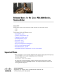
Allied Telesyn International CentreCOM MAC Layer Bridge Models AT-6870 AT-6875 User Manual PN 613-10450-00 Copyright 1996 Allied Telesyn International Corp. All rights reserved. No part of this publication may be reproduced without prior written permission from Allied Telesyn International. Allied Telesyn reserves the right to make changes in specifications and other information contained in this document without prior written notice. The information provided herein is subject to change without notice. In no event shall Allied Telesyn be liable for any incidental, special, indirect, or consequential damages whatsoever, including but not limited to lost profits, arising out of or related to this manual or the information contained herein, even if Allied Telesyn has been advised of, known, or should have known, the possibility of such damages. Trademarks: CentreCOM is a trademark of Allied Telesyn International. Ethernet is a registered trademark of Xerox Corporation. Statement U.S. Federal Communications Warning: This equipment has been tested and found to comply with the limits for a Class A digital device pursuant to Part 15 of FCC Rules. These limits are designed to provide reasonable protection against harmful interference when the equipment is operated in a commercial environment. This equipment generates, uses, and can radiate radio frequency energy and, if not installed and used in accordance with this installation manual, may cause harmful interference to radio communications. Operation of this equipment in a residential area is likely to cause harmful interference in which case the user will be required to correct the interference at his own expense. Note: Modifications or changes not expressly approved of by the manufacturer, can void your right to operate this equipment. Danger: There are no "user-serviceable" parts inside the CentreCOM Multiport Repeater. Due to the danger of exposed high voltage, DO NOT operate or apply power to this product when the cover is removed. This unit should be opened only by a trained and qualified technician. Canadian Department of Communications This digital apparatus does not exceed the Class A limits for radio noise emissions from digital apparatus set out in the Radio Interference Regulations of the Canadian Department of Communications. Le présent appareil numérique n'émet pas de bruits radioélectriques dépassant les limites appicables aux appareils numériques de le Classe A. Prescrites dans le réglement sur le brouillage radioélectrique édicté par le minestére des Communications du Canada. Electrical Notice All Countries: Install in accordance with Local and National Electrical Codes. German Class B Bercheingung des herstellers/importeurs hiermit wird bescheingt, das der AT-3004 oder AT-3004 Multiport Repeater in Uebereinstimmung mit den Bestimmungen der AT-3004 funk-entstoert ist. Der Deutschen Bundespost wurde das Inverkenhrbringen dieses Gerates angezeigt und iii Statement die Berschtigung zur Uberprufung der Serie auf Einhaltung der Bestimmungen eingeraumt. Von benutzer zusammengestellte Systeme, die dieses Gerat beihalten, mussen den Bestimmungen von Vfg 243 entsprechen. Notes The following are examples of special notices used throughout this manual. They are Notes, Cautions, and Warnings. They are defined as follows: Note: This indicates a note of specific interest related to the immediate text in which it is found. Caution: This notice will be related to possible problem areas where caution should be observed to avoid non-life threatening conditions and minor damage to equipment, etc. Warning: This notice will indicate a hazardous condition that may pose the possibility of severe equipment damage, personal injury or death. iv Table of Contents Statement ...................................................................................................................... iii U.S. Federal Communications ............................................................................................................... Canadian Department of Communications .......................................................................................... Electrical Notice ...................................................................................................................................... German Class B........................................................................................................................................ Notes.......................................................................................................................................................... Table of Contents Overview iii iii iii iii iv .......................................................................................................... v ..........................................................................................................................1 CentreCOM MAC Layer Bridge ............................................................................................................. 1 Features ...................................................................................................................................................... 2 Physical Description.................................................................................................................................. 2 Application Guidelines..................................................................................................................................... 4 Overcoming Physical Limitations ........................................................................................................... 4 Increasing Network Performance........................................................................................................... 4 Mixing Media .............................................................................................................................................. 7 Fault Tolerance and Isolation .................................................................................................................. 8 Using Backup Bridges .............................................................................................................................. 9 Installation and Operation ............................................................................................................................ 11 Unpacking ................................................................................................................................................. 11 Site Selection ............................................................................................................................................ 11 Factory Configuration ............................................................................................................................ 11 Operation................................................................................................................................................... 13 Specifications ................................................................................................................15 Software Features ................................................................................................................................... 15 Hardware Features ................................................................................................................................. 15 Performance ............................................................................................................................................. 15 Physical Characteristics ......................................................................................................................... 15 Power Characteristics............................................................................................................................. 15 Accessories ............................................................................................................................................... 16 IEEE 802.3 Quick Primer ............................................................................................17 IEEE 802.3 AUI Drop Cables ............................................................................................................... 17 v Table of Contents IEEE 802.3/10BASE2 (Thin Ethernet)............................................................................................... IEEE 802.3/10BASE5 (Thick Ethernet)............................................................................................. Propagation.............................................................................................................................................. IEEE 802.3 Four Repeater Rule.......................................................................................................... 17 17 17 18 Network Frame Formats ............................................................................................ 19 Power Cords and Plugs .............................................................................................. 21 Glossary ..........................................................................................................................23 Warranty and Service Information vi .........................................................................25 Chapter 1 Overview CentreCOM MAC Layer Bridge ❑ ❑ AT-6870 AT-6875 Learning Bridge SNMP Manageable Learning Bridge IEEE 8023 Compliant Ethernet Compatible The CentreCOM Bridges allow two IEEE 802.3 sub-networks to be connected into a single network. Each sub-network may be IEEE 802.3 Ethernet or thin Ethernet. The CentreCOM Bridges transparently forward packets between both networks. Since these bridges operate at the MAC level, all higher level protocols, such as TCP/ TP, DECnet™, and Netware™, are passed unaffected. Many common Local Area Network (LAN) problems are solved by the CentreCOM Bridges. For example, the effective length of a network can be increased by adding CentreCOM Bridges. Moreover, placing the bridges at natural boundaries of the workgroups increases the network performance in each segment. The reliability of a large network can be enhanced through subnetting with CentreCOM Bridge, which allows heterogeneous sub-networks to be interconnected. The CentreCOM Bridges support high performance requirements including packet filtering at 25,000 packets per second and sustained forwarding at 12,500 packets per second. The CentreCOM Bridges' address filter table supports 2048 station addresses. With this high performance, the AT-6870 and the AT-6875 do not lose data during peak network traffic periods. Multiple CentreCOM Bridges can be used as backups in case of network failure. The AT-6870 and AT-6875 support the IEEE 802.1 STP, which provides redundancy link management and network loop checking. STP allows backup bridges to provide fault tolerant networks by placing the bridges that form loops into a standby state until an active bridge fails. When failure occurs, the network is reconfigured and any loops are eliminated. This network reconfiguration occurs without impacting the network users or the applications. 1 Overview The TCP/IP SNMP is supported by the AT-6875. The bridge can be monitored and manipulated by many SNMP compatible management stations. Several parameters of the AT 6875 can be managed under SNMP including custom filtering, static forwarding entries, and STP. Features ❑ ❑ ❑ ❑ ❑ ❑ ❑ ❑ ❑ ❑ ❑ Physical Description Self-learning MAC layer bridges Filter at 25,000 PPS Forward at 12,500 PPS Two media options per network segment, thin (10BASE2) or AUI (10BASE5) Supports up to 2,000 MAC addresses in filter table IEEE 802.1 revision D Spanning Tree Protocol (STP) Standalone or rack mount installation Simple Network Management Protocol (SNMP) Management Information Base II (MIB II) One year free software upgrades One year warranty The CentreCOM MAC Layer Bridge is packaged in a sturdy two piece sheet metal enclosure with ventilation slots on the side and back. All network attachments and power connectors are on the back panel; status indicators are on the front. The bridge configuration is controlled by the jumpers on the main board inside the chassis. The top cover is attached to the main chassis by two screws on each side. Front Panel Six LEDs are on the bridge front panel (see Figure 1), arranged as two sets. The first set contains two lights which display power and diagnostic indications. The other set contains four network activity LEDs. Figure 1: AT-6870 Front Panel The names of each LEDand their functions are shown below in Table 1. Light Function PWR System Power DIAG Diagnostic Testing Status TX1 Channel 1 Transmitting Table 1: AT-6870 Front Panel 2 AT-30xxTR Multiport Repeater Light Function RX1 Channel 1 Receiving TX2 Channel 2 Transmitting RX2 Channel 2 Receiving Table 1: AT-6870 Front Panel Back Panel The back panel contains the following elements, shown in Figure 2: ❑ ❑ ❑ ❑ ❑ ❑ ❑ IEC-320/CEE-22 compatible power connector. Channel 1 connector for Ethernet or IEEE 802.3 10BASE5. Channel 1 thin Ethernet coaxial connector. Channel 2 connector for Ethernet or IEEE 802.3 10BASE5. Channel 2 thin Ethernet coaxial connector. Fan vent. Removable expansion slot cover. Figure 2: AT-6870 Back Panel The Ethernet/lEEE ffO2.3 10BASE5 network connector uses screw lock fasteners to ensure secure connections. These ports use a DA-15P male connector. Product Code and Serial Number A label on the bottom of each CentreCOM MAC Layer Bridge indicates the product code and serial number. If you need to call Allied Telesyn Technical Support, have these numbers ready. 3 Overview Application Guidelines Overcoming Physical Limitations This section shows how bridges can be used to overcome common physical limitations. The next section shows how to do this in such a way that network performance is improved. Maximum Network Length A bridge can be used to link several networks serially (see Figure 3) in the same way as a repeater is used. The maximum network length only applies to individual networks, so that the overall network length is not bound by any limit. However, because each bridge introduces a small delay in forwarded traffic, there are practical limits on how many bridges can be used in this manner. Maximum Number of Stations The maximum number of stations attached to a single network is 1024. As more stations are added, the number of collisions increases and performance degrades. Bridges can be used to solve this problem. Although there is effectively no limit on the number of nodes that can be attached to a bridged network, there are some practical considerations. Once again, this is due to the delay introduced by each bridge through which a frame traverses. Figure 3: Extending Network Length Increasing Network Performance Work Groups This section discusses the clustering nature of network users and how bridges can take advantage of this to provide dramatic performance improvements. Most companies are divided into groups. These groups exist at many levels. At one level there may be separate divisions, and within a division there are usually teams of people associated with a project or department. The important thing to realize about these groupings, which are often referred to as Work Groups, is at the communication between members of a group is of a much higher bandwidth than that between groups. This communication includes interpersonal communication as well as transfer of data between computers. These groups must also be able to communicate with each other, though this will be of a lower bandwidth. 4 AT-30xxTR Multiport Repeater Placement of Bridges in a Network The key to effective use of a bridge is to find the Work Groups within your organization and to place bridges between the networks in different groups. Network traffic within each Work Group is isolated by a bridge and has no effect on the overall network. When computers from different groups need to communicate, bridges allow them to do so transparently, as if there were just one big network. Simple Bridged Network . In many cases, Work Group boundaries are clearly defined, and it is obvious where to place bridges. This is especially true for small organizations, which will only use one or two bridges, or when previously disjointed networks are being interconnected. Figure 4 below shows this kind of configuration. Figure 4: A Simple Bridged Network Analysis of Large Networks . When a large existing network must be broken up into smaller pieces, it is useful to perform a thorough analysis of the network traffic patterns. With e aid of a network monitor, you can determine the amount of traffic between each node on the network. Work Group boundaries exist at the points where the smallest amount of traffic passes. Bridges should always be placed at the point of minimum traffic. For example, consider the network shown in Figure 5. This network has four nodes. The traffic patterns are shown in Table 2. Figure 5: Analysis of Traffic Patterns 5 Overview From To Frames/Second (Average) 1 2 9000 1 2 1000 1 4 1000 2 3 1000 2 4 1000 3 4 9000 Table 2: Traffic Between Nodes In this case there are two clusters. The first contains nodes 1 and 2, and the second contains nodes 3 and 4. Within each cluster, the traffic levels are around 13000 frames per second, while the traffic between the groups is around 4000 per second. A bridge could be placed between nodes 2 and 3. Note that placing a bridge between nodes and 2 in this case would make the overall performance worse, because the traffic between these two stations (130(0 frames/sec) is higher than the throughput of most bridges. As the network becomes larger it becomes increasingly difficult to find the group boundaries without the assistance of network analysis application programs. Some network installers can provide a network analysis service to help you decide where to place bridges. Network Topology A bridged network takes on one of two basic forms. The first is a cascaded network, where a set of networks are connected together by a series of bridges. An example of this configuration is given in Figure 6. A cascaded network is useful when a small number of bridges is being used. If many bridges are used, the delay associ ated with each bridge may accumulate to unacceptable levels between networks at the extremities. Figure 6: A Cascaded Bridged Network The second form used is a tree topology. The simplest form of a tree topology is one level deep and is known as a backbone network. Figure 7 shows this type of network. ln a backbone network, each Work Group has its own network, and there is one network used only for communicating between the Work Groups. The advantages of a tree network far outway the need for an additional network, and are listed below: 1. 6 There is never more than two bridges between any two networks. The delays introduced by bridges are therefore minimized. AT-30xxTR Multiport Repeater 2. As long as the backbone network is operating correctly, any fault within a Work Group has no effect on other Work Groups. 3. Network faults are isolated to a single Work Group and are therefore easier to find. Figure 7: A Backbone Network Mixing Media The AT-6870/ AT-6875 MAC layer bridge can also be used to interconnect networks that use different media. You may use Thin Ethernet on one channel, and Ethernet on the other channel. This is not a good enough reason to use a bridge, however, since inexpensive conversion devices are available. If you do need to install a bridge and you need to interconnect Thick and Thin Ethernet, the CentreCOM MAC Layer Bridge can save space and money because it has built-in Thin Ethernet tranceivers. Figure 8 shows a bridged network containing Ethernet subnetworks. Figure 8: Mixing Media 7 Overview Fault Tolerance and Isolation A single large network has several problems relating to faults. Two are listed below: 1. If the network fails all users lose connectivity. 2. Because of the network size, it may take a long time to find the fault. Figure 9 shows the failure of a simple network. Figure 9: Failure on a Simple Network When bridges are used, a network becomes much more fault tolerant. This is especially true if a backbone network topology is used. With a cascaded network, a fault will split the network into two disjointed parts. This is shown in Figure 10. Figure 10: Failure of a Cascaded Bridged Network In a backbone network two possibilities arise. If the backbone fails, the network will be partitioned into as many partitions as there are networks attached to the backbone. However, in the more common case of a failure within one of the attached networks, only that network is affected, while all other networks can still communicate with each other. This is shown in Figure 11. 8 AT-30xxTR Multiport Repeater Figure 11: Failure of a Backbone Network A bridged network is therefore inherently more fault tolerant, providing service to many users even when network components fail. This has the side effect of making it much easier to isolate the cause of the network fault. Since only a small part of the bridged network fails, this provides a much smaller area within which to search for a problem. Using Backup Bridges The CentreCOM MAC Layer Bridge uses the IEEE 802.1 draft standard STP to determine the network topology. If more than one bridge is connected between the same two networks, one bridge will automatically be designated as the master, and the others as slaves. Only the master may forward traffic. If the master fails, however, one of the slave bridges will become the new master and take over forwarding responsibility. Figure 12: Using a Backup Bridge 9 Overview The network depicted in Figure 12 would continue to operate if one of the bridges was turned off accidentally, or if a cable between one of the bridges and a network was unplugged. Figure 13: Advanced Use of Backup Bridges By using backup (or redundant) bridges, it is possible to design a network topology that is extremely resilient to failure. Unlike a normal bridged network, which minimizes the loss of network availability, networks with backup bridges may eliminate loss of availability even with multiple network failures. Figure 13 shows a network configured in such a fashion. Each subnetwork is connected to a single backbone network, and also to each of its neighboring networks. Networks A and B can still communicate after the failure of any other two networks. 10 AT-30xxTR Multiport Repeater Installation and Operation Unpacking Rough handling during shipping can damage electronic equipment. After you unpack the CentreCOM MAC Layer Bridge, check carefully for possible damage. If you notice any damage, contact the shipper. Direct any additional questions about damage to the distributor from whom the unit was purchased, or contact Allied Telesyn: Allied Telesyn International 950 Kifer Road Sunnyvale, CA 94086 Tel: 1 (800) 424-4284 Fax: 1(408) 736-0100 Save the shipping carton and packing material in case you need to store or ship the bridge back in the future. Site Selection TheCentreCOM MAC Layer Bridge should be placed in a cool, wellventilated area. Air vents are located on each side of the bridge. The back of the unit also has a fan vent. It is very important that none of the air vents are obstructed by any material, wall, or other equipment. There should be several inches of clearance between these vents and any other object. Failure to follow these ventilation guidelines may result in overheating and eventual damage of the bridge. Factory Configuration Changing The Factory Configuration The CentreCOM MAC Layer Bridge is configured at the factory to use Ethernet or IEEE 802.3 10BASE5 on both channels. If the bridge is used in this environment, no additional configuration is required. To use the bridge in other modes, some jumpers inside the unit must be relocated. To do this, follow the directions below: 1. Remove the power plug. 2. Remove the two screws on each side of the bridge that hold the top cover in place. 3. Remove the top cover. The cover fits tightly, and it may be necessary to use a screwdriver to initially dislodge the cover. 4. If necessary, carefully remove thin-Ethernet transformers with an IC puller or a flat screwdriver. Reposition and install the transformers at the specified location. Check for bent pins or a shifted transformer. 5. Replace the top cover and screws. Caution: Make sure that the power cord is removed from the bridge before opening the cover. 11 Overview Settings Figure 14: Location of Headers and Transformers Thin Ethernet Transformer . Each channel has a transformer IC component that is only for thin Ethernet operation. This component must be moved to a spare socket if thin Ethernet is not used. The placement of these transformers is given below in Table 3 Network Type Channel 1 Channel 2 Ethernet T4A (Thick) T2A (Thick) IEEE 802.3 10BASE5 T4A (Thick) T2A (Thick) Thin Ethernet T4 (Thin) T2 (Thin) Table 3: Thin Ethernet Transformers Configuring Channel 1 Note: Channel 1 is set at the factory to operate with Ethernet or IEEE 803.2 10BASE5. Setting Channel 1 for Thin Ethernet Operation: 1. Remove any transformer in position T4A. 2. Install the transformer into position T4. Setting Channel 1 for Ethernet or IEEE 802.310BASE5 Operation: (Channel 2 Factory Setting) 12 AT-30xxTR Multiport Repeater 1. Remove any transformer in position T4. 2. Install the transformer into position T4A. Configuring Channel 2 Note: Channel 2 is set at the factory to operate with Ethernet or IEEE 803.2 10BASE5. Setting Channel 2 for Thin Ethernet Operation: 1. Remove any transformer in position T2A. 2. Install the transformer into position T2. Setting Channel 2 for Ethernet or IEEE 802.3 10BASE5 Operation: (Channel 2 Factory Setting) 1. Remove any transformer in position T2. 2. Install the transformer in position T2A. Operation Power On When the power is first applied, the green PWR and red DIAG LEDs will be lit. Each of the four green network activity LEDs will be OFF. Diagnostics The CentreCOM MAC Layer Bridge executes a comprehensive set of diagnostics when the power is first applied. The red DIAG LED will flash ON for each test that is executed. After successfully executing the diagnostic tests, the DIAG LED will be turned OFF. If any tests fail, the DIAG LED will remain ON. In the latter case, the bridge should be resumed for service. Normal Operation Under normal operation, the four green activity LEDs will reflect the reception and transmission of data packets on each channel. The activity LEDs have the following meaning (Table 4): Name Meaning When On TX1 Channel 1 is forwarding a packet RX1 Channel 1 is receiving a packet TX2 Channel 2 is forwarding a packet RX2 Channel 2 is receiving a packet Table 4: Activity LEDs The CentreCOM MAC Layer Bridge contains software that allows two or more bridges to interconnect the same two networks. This feature allows the use of backup bridges that take over when a bridge or its network connection fails. The bridges communicate with each other to implement this feature. Because of this, the activity LEDs will always blink about once every few seconds, even if there is no other network activity. Troubleshooting The next thing to check is that both network connections are firmly made to the bridge and to the network. 13 Overview The network itself may be faulty. This can usually be checked independently of the bridge by establishing communication between two computers that are directly attached to the network. Finally, you should check that the bridge configuration matches the network attachments being used. Turn off the power and remove the power cord from the bridge. Remove the cover and inspect the intemal configuration. Refer to the earlier section on bridge configuration for the correct settings and make sure that: 14 1. All shunts are firmly installed in the correct locations. 2. The thin Ethernet transformers are inshiled in.the correct locations. 3. The thin Ethernet transformers do not have any bent pins. 4. The thin Ethernet transformers have all the pins inserted in the socket. 5. The thin Ethernet transformers are not shifted in the socket. Chapter 2 Specifications Software Features Hardware Features Compliant with IEEE 802.1 STP specification UDP/IP protocol support Dynamic forwarding table creation SNMP network management agent Power-on diagnostics Custom filtering criteria Networks Memory Performance Physical Characteristics Forwarding Rate Filtering Rate Dimensions Weight Temperature Operating Storage Relative Humidity IEEE 802.3 10BASE5 compliant Ethernet version 1.0 and 2.0 compatible IEEE 802.3 10BASE2 (thinnet) 512K EPROM 128K Frame Buffer RAM 32 bytes EPROM 512K system RAM 12,500 packets per second 25,000 packets per second 43.2 cm x 24.7 cm x 6.6 cm (17.0 in.x 9.7 in. x 2.6 in.) 4.4 kg (9 lb. 12.2 oz.) 0° C to 50° C -20° C to 60° C 5% to 80% non-condensing Electrical/Mechanical Approvals Power Characteristics EMI Safety FCC, CSA UL, CSA, TUV-GS Parameter Input voltage 110 VAC 220 VAC Power consumption Typical 47 to 63 Hz 90 to 135 VAC 180 to 270 VAC 50 watts 15 Specifications Accessories 16 Part No. AT-RKMT-2 AT-RKMT-3 AT-1250 ATBRKT-13 Description Rackmount kit for 19 in. rack Rack mount “ears” kit for 19 in. rack UL listed power cord Cable strain relief Appendix A IEEE 802.3 Quick Primer IEEE 802.3 AUI Drop Cables AUI or "drop cables" can be no longer than 50 meters (164 feet) each. Attachments may be made only to the cable ends at the 15 pin D-shell connector. AUI drop cables may have a maximum 257ns propagation delay for computing the worst case propagation delay of a cable system. AUI cable propagation delay is about 5.13 ns/meter. This cable internally consists of four shielded twisted pair wires with an overall shield and drain wire; a 15 pin D-shell male connector at one end and a 15 pin D-shell female connector at the other end. Cable impedance is typically 78Ω. The AUI cable typically connects a transceiver attached to a coaxial segment to a Data Terminal Equipment (DTE) workstation. IEEE 802.3/10BASE2 (Thin Ethernet) When configuring thin coax segments, IEEE 802.3 specifications allow 29 or fewer Media Attachment Units (MAUs) per cable segment spaced at no less than .5 meter. The IOBASE2 (thin) cable length can not exceed 185 meters (600 feet) per 10BASE2 (thin) cable segment. The worst case propagation delay for a 185 meter thin Ethernet segment is 950.9 ns. The propagation delay for 10BASE2 (thin Ethernet) cable is 5.14 ns/meter. Both ends of the segment must be terminated with a 50Ω termination with a power rating of .5 watts or greater. Earth grounding of the segment shield must take place only at one point on the cable. IEEE 802.3/10BASE5 (Thick Ethernet) When configuring thick coax segments, IEEE 802.3 specifications allow 100 MAU attachments or less, spaced at multiples of 2.5 meters measured accurately from the cable end (50Ω terminator included). The thick cable segment can not exceed 500 meters (1640 feet) in length. Worst case "end to end" propagation delay of a thick coax segment is 2165 ns. Propagation delay of thick Ethernet coax is calculated at 4.33 ns/meter. Both ends of the segment must be terminated with a 50Ω termination with a power rating of .5 watts or greater. Earth grounding of the segment shield must take place only at one point on the cable. Propagation Round-trip propagation delay through-out the entire cable system, from farthest ends, may not exceed 51.7µs to -4 µs. Propagation delay is the time it takes a signal to travel from the input of a system component to the output. Propagation delay is usually measured in nanoseconds. IEEE 802.3 has specific propagation delay maximums for the Ethernet components. Cable length plays a major role in propagation delay. (i.e, a 50 meter AUI cable has a maximum propagation delay of 257ns.) The propagation’s delay of cable is dependent on length and velocity factor of the cable type. 17 IEEE 802.3 Quick Primer IEEE 802.3 Four Repeater Rule 18 No more than four repeaters may be linked to connect five segments and no other attachments may be on the linking segments. If attachments are present on the repeater coax link segments, then no more than two repeaters linking three segments may be configured. These limitations are set to keep propagation delay packet jitter, and signal attenuation to within acceptable standards. Appendix B Network Frame Formats The Ethernet and IEEE 802.3 specifications define slightly different frame header formats. Both Ethernet and IEEE 802.3 use two 6 byte source and destination addresses, but the following two byte field is interpreted as a packet type by Ethernet and as a packet length by IEEE 802.3. Figure 15 shows the Ethernet and IEEE 802.3 frame formats. Figure 15: Ethernet and IEEE 802.3 Frame Formats The CentreCOM MAC Layer Bridge only inspects the frame source and destination addresses, so that it will pass packets between Ethernet and IEEE 802.3 networks. However, hardware attached to the Ethernet network will net correctly interpret the forwarded IEEE 8()2.3 frame and vice-versa. 19 Network Frame Formats Note that this problem exists only at the MAC interface level, and is independent of the higher level protocols being used, such as TCP/IP. Therefore, systems which use Ethernet and IEEE 802.3, may not be able to communicate with each other even though they use the same higher level protocol. Many vendors’ interfaces can recognize both IEEE 802.3 and Ethernet frames on the same network. This is done by using Ethernet packet types that are greater than the maximum frame length. Packets with legal frame length fields are assumed to be IEEE 802.3 format while others are assumed to be Ethernet format. You may consult the supplier of your network hardware and software products to ascertain what the effects of mixing Ethernet and IEEE 802.3 networks will be. 20 Appendix C Power Cords and Plugs A standard power supply cord is shipped with all units sold in the United States. For units shipped internationally, the customer must supply a power cord that meets the regulations of the country where the bridge is operated. The following power cords may be used with the CentreCOM MAC Layer Bridge shown below: Basic Cord Type Equivalent Cord Types SP-2 SPE-2, SPT-2 SP-3 SPE-3, SPT-3 SV SVE, SV0, SV00, SVT, SVT0, SVT00 SJ SJE, SJ0, SJ00, SJT, SJT0, SJT00 S SE, S0, S00, ST, ST0, ST00 Table 5: Power Cords The power cord selected should meet all regulations, such as maximum length and range, which apply in the country of operation. The power cord should have a receptacle to fit in an IEC-320/CEE-22 standard power input connector. 21 Appendix D Glossary 10BASE5 - Also called thick Ethernet, 10BASE5 is a 10 Mhz, Baseband, 500 meter coaxial segment. The cable is also refered to as "yellow" cable. Cable impedance is 50Ω. Thick Ethernet cable is typically used as a trunk or backbone path of the network. 10BASE2 - Also called thin net or CheaperNet, 10BASE2 is a 10 Mhz, Baseband, 185 meter coaxial segment. Cable impedance is 50Ω. AUI - The Attachment Unit Interface is the cable connection from an MAU (transceiver) to a DTE (typically a workstation) consisting of a 15 conductor twisted pair cable of 50 meters maximum length. BNC SERIES - A 10BASE2 thin coax connector with push-on bayonet locking lug that quickly locks into place with a half twist. COAX SEGMENT - A segment of Ethernet cable that contains a MAU. 15 PIN D CONNECTOR - The AUl cable uses 15 pin D-connectors. D refers to the shape of the connector shell. Also called miniature D, DB-15, or DIX connectors. DIX CONNECTOR - see D CONNECTORS. DTE - Data Terminal Equipment is connected to the MAU with an AUI cable. The DTE could be a Ethernet workstation, repeater, or bridge. HEARTBEAT - see SQE IMPEDANCE - Impedance is an electrical characteristic of a circuit dealing with the combination of the AC and DC resistance and the appearance of that resistance to attached circuits. JABBER - The jabber function is the MAUs ability to automatically inhibit the transmit data from reaching the medium if the transmit data time length exceeds 150 ms. duration. This protects the medium from being overrun with data packets from a possibly defective device. JITTER - Jitter is the fluctuation of the data packet in respect to a standard clock cycle. Jitter is undesirable and must be minimized. SQE - Signal Quality Error test, commonly refered to as heartbeat is a special 802.3 signal sent by the MAU to the DTE indicating that a multiple transmission (which is illegal) has occured. 23 Glossary THICK ETHERNET - see 10BASE5. THIN ETHERNET - see 10BASE2. LINK SEGMENT - The link segment of coaxial cable is a segment which has no MAU devices but links two Local Area Network (LAN) devices together such as repeaters. MAU - Media Attachment Unit or transceiver, provides an electrical attachment to a 10BASE2 or 10BASE5 coaxial cable segment. The MAU will convert the IEEE 802.3 composite signal into separate signals for Data In (circuit A and B), Data Out (circuit A and B), Control In (circuit A and B), Control Out (circuit A and B), Voltage Plus and Voltage Common. N SERIES - A barrel shaped, threaded connector used on 10BASE5 (thick Ethernet) coaxial cable. PROPAGATION DELAY - The time it takes a signal to travel from the input of a system component to the output. Usually measured in nanoseconds. IEEE 802.3 has specific propagation delay maximums for computing propagation budgets when designing a LAN. Cable length plays a major role in propagation delay. (i.e, a 50 meter AUI cable has a maximum allowable propagation delay of 257 ns.) The propagation delay of cable is dependent on length and velocity factor of the cable type. There are also propagation delays associated with electronics attached to the system. 24 Appendix E Warranty and Service Information Allied Telesyn International Corp. (ATI) warrants to the original consumer/ purchaser that each of its products, and all components thereof will be free from defects in materials and/or workmanship for one year (two years on CentreCOM 100, 125, 126, 150, 200, 250, 270, 440, 470, and MX Series transceivers) from the original date of purchase. Any warranty hereunder is extended to the original consumer/purchaser and is not assignable. In the event of a malfunction or other indication of product failure attributable directly to faulty workmanship and/or materials, ATI will, at its option, repair or replace the defective product or components at no additional charge as set forth herein. Repair or replacement product will be furnished on an exchange basis and will be either reconditioned or new at the option of ATI. All replacement parts become the property of ATI. This limited warranty does not include service to repair damage to the product resulting from accident, disaster, misuse, neglect or modification of the product. Service under this warranty may be obtained by returning the product to ATI, and only after receiving authorization by ATI by issuance of a Return Material Authorization (RMA) number, with shipping charges prepaid, in the original shipping container or like container, and with proof of date of purchase included with the returned product. The RMA number MUST be marked clearly visable on the outside of the shipping container. Any material returned without such RMA markings shall be rejected and returned to sender unopened. There shall be no warranty for either parts or labor after the expiration date of one year (two years on CentreCOM 100, 125, 126, 150, 200, 250, 270,440,470, and MX Series transceivers) from the original date of purchase, unless the original consumer/purchaser has purchased an Extended Warranty. Warranty beyond the first year (second year for CentreCOM 100, 125, 126, 150, 200, 250, 270, 440, 470 and MX Series transceivers) is subject to the terms of the extended warranty program purchased. Products will be returned to the customer after repair or replacement has been completed and by the carrier and method of delivery chosen by ATI, to any destination within the United States of America. If the customer desires some other specific form of conveyance, or is located beyond U.S.A. borders, then the customer shall bear the cost of the return shipment. 25 Warranty and Service Information ATI makes no express or implied warranties including, but not limited to, any implied warranty of merchantability or fitness for a particular purpose, except as expressly set forth in this warranty. In no event shall ATI be liable for incidental or consequential damages, cost, or expenses arising out of or in connection with the use or performance of the product delivered hereunder. Some governments do not allow the exclusion or limitation of incidental or consequential damages for consumer products, so the above limitation of exclusion may not apply to you. To aid in an expeditious repair, please record the following information and have it available when consulting ATI for warranty service. Date of Purchase: Place of Purchase: Serial Number: Allied Telesyn International 950 Kifer Road Sunnvale, CA 94086 Technical Support 1 (800) 428-4835 Telephone: (800) 424-4284 Fax: (408) 736-0100 26