1
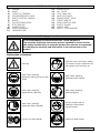
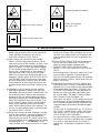
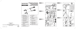
A EC Declaration of Conformity
The undersigned, authorised by E.O.P.I., declares that the following products:
Petrol Brushcutter 34-38-42-46cc, manufactured by E.O.P.I., Valmadrera,
Italia, are in accordance with the European Directives 98/37/EEC (Machinery
Directive), 93/68/CEE (CE Marking Directive) & 89/336/CEE (Directive on
electromagnetic compatibility), directive 2000/14/CEE (Annex V).
DE
CE Konformitätserklärung
Der Unterzeichnete, bevollmächtigt durch E.O.P.I., erklärt, daß
folgende Geräte: Benzin Motorsensen 34-38-42-46cc, hergestellt
durch E.O.P.I., Valmadrera, Italia, den Europäischen Richtlinien
98/37/EEC (Maschinenrichtlinie), 93/68/CEE (CE
Kennzeichnungsrichtlinie) & 89/336/CEE (EMV Richtlinie) entsprechen,
richtlinie 2000/14/CEE (Anhang V).
Déclaration de conformité Européenne
FR
Le soussigné, dûment mandaté par E.O.P.I., déclare que les produits
suivants: Petrol Brushcutter 34-38-42-46cc, fabriqués par E.O.P.I.,
Valmadrera, Italia, sont conformes aux Directives Européennes 98/37/EEC
(Directive Sécurité Machine), 93/68/CEE (Directive Marquage CE) &
89/336/CEE (Directive EMC), directive 2000/14/CEE (Annexe V).
F EG Conformiteitsverklaring
Ondergetekende, gemachtigd door E.O.P.I., verklaart dat de volgende
produkten: Benzine Bosmaaier 34-38-42-46cc, geproduceerd door E.O.P.I.,
Valmadrera, Italia voldoen aan de Europese Richtlijnen 98/37/CEE (Machinerie
Richtlijn), 93/68/CEE (EG Markering Richtlijn) & 89/336/CEE (Richtlijn
aangaande elektromagnetische compatibiliteit), richtlijn 2000/14/CEE (Annex V).
NO
EF Erklæring om Overensstemmelse
Undertegnede, autorisert av E.O.P.I., erklærer at f¯øgende produkt
Bensindrevet gress/krattrydderen 34-38-42-46cc, konstruert av E.O.P.I.
23868 Valmadrera (Lecco) Via Como, 72 Italia, er i overensstemmelse med
føgende europeiske direktiver: 98/37/CEE (Maskineridirektiv), 93/68/CEE (CEmerkingsdirektiv) & 89/336/CEE (Direktiv om elektromagnetisk kompatibilitet),
direktiv 2000/14/CEE (Annex V).
FI
EY Julistus Vastaavuudesta
Allekirjoittanut, E.O.P.I. in valtuttaamana, vakuuttaa että seuraavat
tuotteet: Polttomoottorikäyttöinen pensasleikkuri 34-38-42-46cc,
ja jotka on valmistanut E.O.P.I., Valmadrera, Italia, ovat Euroopan
direktiivien 98/37/EEC (Koneisto-direktiivi), 93/68/CEE (CE Merkintädirektiivi) & 89/336/CEE (Elektromagneettinen Yhteensopivuusdirektiivi) mukainen, direktiivi 2000/14/CEE (Liite V).
SE
ELITE 3325-3425/34 cc
ELITE 3825-3925-3930/38 cc
ELITE 4230x-4330x-4330XPRO/42 cc
ELITE 4630x-4730x-4730XPRO/46 cc
B 342 X / 34 CC
B 412 X - B 422 X / 42 CC
B 462 X - B 472 X / 46 CC
: EU Overensstemmelseerklæring
Undertegnede, bemyndiget af E.O.P.I., erklærer herved, at følgende
produkter: Benzindrevet Græstrimmer 34-38-42-46cc, E.O.P.I.,
Valmadrera, Italia, er i overensstemmelse med de eurpæiske direktiver
98/37/EEC (Maskineri direktiv), 93/68/CEE (CE mærkningsdirektiv) &
89/336/CEE (EMC-direktiv), direktiv 2000/14/CEE (Annex V).
ES
Declaracion de cumplimiento de la directriz de la UE
El abajo firmante, autorizado por E.O.P.I., afirma que los siguientes
productos: Desbrozador Gasolina 34-38-42-46cc, fabricados por E.O.P.I.,
Valmadrera, Italia, cumplen con las directivas Europeas 98/37/EEC (Directiva
sobre Maquinaria), 93/68/CEE (Directiva sobre Marcas de la CE) &
89/336/CEE (Directiva sobre ‘Compati-bilidad Electro Magnética’), directiva
2000/14/CEE (Anexo V).
PT
D
Partner McCulloch
oil
oil
40:1
50:1
2%
1 ltr
O abaixo assinado, autorizado por E.O.P.I., declara que os seguintes produtos:
Roçadora a Gasolina 34-38-42-46cc, fabricada por E.O.P.I., Valmadrera,
Italia. estão de acordo com as Directivas Europeias 98/37/EEC Directiva de
Maquinaria), 93/68/CEE (Directiva de Marcação CE) e 89/336/CEE (Directiva
de Compatibilidade Electromagnética), directiva 2000/14/CEE (Apêndice V).
IT
Dichiarazione di Conformità CE
E1
Il sottoscritto, autorizzato dalla E.O.P.I., dichiara che i seguenti prodotti:
Decespugliatori 34-38-42-46cc, costruito da E.O.P.I., Valmadrera, Italia,
sono conformi alle Direttive Europee: 98/37/EEC (Direttiva Macchine),
93/68/CEE (Direttiva Marcatura CEE) & 89/336/CEE (Direttiva Compatibilità
Elettromagnetica), direttiva 2000/14/CEE (Allegato V).
HU
B1
B2
B3
B4
B5
B6
E2
80
100
160
5
100
125
200
10
200
250
400
20
400
500
800
E3
Technikai leírások
@ ∆ήλωση Συµµρφωσης προς τις Eντολές της EE
INSTRUCTION MANUAL
GB
Valmadrera, 15.12.01
Pino Todero (Direttore Tecnico)
E.O.P.I.
Electrolux Outdoor Products
Via Como 72
23868 Valmadrera (Lecco)
ITALIA
Phone +39 0341 203111 - Fax +39 0341 581671
Our policy of continuous improvement means that the specification of products may be altered from time to time without prior notice.
Electrolux Outdoor Products manufacture products for a number of well known brands under various registered patents, designs and
trademarks in several countries.
© Electrolux Outdoor Products Italy
The Electrolux Group. The world’s No.1 choice.
BRUGERHÅNDBOG
DK
BETRIEBSANWEISUNG
DE
EG-försäkran om överensstämmelse
IMPORTANT INFORMATION: Please read these instructions
carefully and make sure you understand them before using
this unit. Retain these instructions for future reference.
WICHTIGE INFORMATION: Lesen Sie diese Hinweise zur
Handha-bung des Geräts aufmerksam durch. Verwenden
Sie es erst, wenn Sie sicher sind, daß Sie alle
Anweisungen verstanden haben und gut aufbewahren.
MANUEL D’INSTRUCTIONS
FR
RENSEIGNEMENTS IMPORTANTS: Avant d’utiliser cet
appareil, veuillez lire atentivement les instructions et
assurez-vous de les avoir comprises. Conservez les
instructions pour référence ultérieure.
BELANGRIJKE IMPORTANTS: Lees deze handleiding
aandachtig en zorg dat u ailes begrijpt alvorens de kettingzaag
te gebrulken en be-waar ze voor toekomstige raadpleging.
PT
VIKTIG INFORMASJON: Les disse anvisningene nøye
og forsikre deg om at du forstår dem før du bruker
enheten og oppbevar dem for sen-ere bruk.
The Electrolux Group is the world’s largest producer of powered appliances for kitchen, cleaning and outdoor use. More than 55 million
Electrolux Group products (such as refrigerators, cookers, washing machines, vacuum cleaners, chain saws and lawn mowers) are
sold each year to a value of approx. USD 14 billion in more than 150 countries around the world.
TÄRKEÄÄ TIETOA: Lue nämä ohjeet huolellisesti ja
varmista, että olet ymmärtänyt ne, ennen kuin alat
käyttää tätä laitetta ja säilytä myöhempää tarvetta
varten.
BRUKSANVISNING
SE
VIKTIG INFORMATION: Läs instruktionerna noggrant och
försäkra dig om att du förstår dem innan du använder
utrustningen och spara dem för framtida behov.
C1
C2
F2
F4
C3
INFORMAZIONI IMPORTANTI: Leggere le istruzioni
attentamente e capirle bene prima di usare l’utensile.
Conservare per ulteriore consultazione.
F3
F3
HASZNÁLATI ÚTMUTATÓ
HU
Jótállást vállalni csak rendeltetésszerüen használatba
vett gépekre tudunk. Kérj ü hogy a gép használatba
vétele elött gondosan olvassa el a kezelési utasításokat.
C4
C5
EΓXEIPI∆IO XEIPIΣMOE
OHJEKIRJA
FI
INFORMAÇÕES IMPORTANTES: Queira ler
cuidadosamente estas instruções e tenha certeza de
entendë--las antes de usar a serra e guarde para
consulta futura.
F1
LIBRETTO D’ISTRUZIONI
IT
BRUKERHÅNDBOK
NO
INFORMACIÓN IMPORTANTE: Lea atentamente las
instrucciones y asegúrese de entenderlas antes de
utilizar esta aparato. Conserve las instrucciones para la
referencia en el futuro.
MANUAL DO OPERADOR
HANDLEIDING
NL
VIGTIGE OPLYSNINGER: Læs instruktionerne
omhyggeligt, før du bruger enheden og gemme til
senere henvisning.
MANUAL DE INSTRUCCIONES
ES
GR
ΣHMANTIKEΣ ΠΛHPOΦOPIEΣ: ∆ιαβάστε
πρoσεxτιxά αvτές τις οδηγίες xαι Φρovτίστε vα τις
xαταvoήσετε αvτ τo µηχάvηµα xαι Φuλάξτε το για
vα το σuµβοuλεύεστε στο µέλλοv.
F5
F3
F3
4%
20 cm3 25 cm3 40 cm3
Alulírott, rendelkezve a E.O.P.I. engedélyével, kijelenti, hogy a
jelentermék 34-38-42-46cc, melyet a E.O.P.I. 23868 Valmadrera (Lecco)
Via Como, 72 Italia, gyártott, megfelel az európai szabványoknak:
98/37/CEE (gépekre vonatkozó), 93/68/CCE (márkázásnak) és
89/336/CEE (elektromágneses összeegyeztetehetöségnek) megfelenek,
direktíva 2000/14/CEE (Melléklet V).
O υπογεγραµµένος, µε eξουσιοδτηση της E.O.P.I., δηλώνει τι τα
εξής προϊντα: Kλαδευτήρι Bενζίνης για Θάµνους 34-38-42-46cc,
κατασκευασθέντα απ την E.O.P.I., Valmadrera, Italia, HΠA
ανταποκρίνονται προς τις Eυρωπαϊκές Eντολές 98/37/CEE (η περί
Mηχανηµάτων Eντολή), 93/68/CEE (η περί του Σήµατος CE Eντολή) &
89/336/CEE (η περί Hλεκτροµαγνητικής Συµβαττητας Eντολή),
Aηρεκτηβα 2000/14/CEE (Πρηπο επηε V).
2,5%
2T
oil
25:1
4
Declaração de Conformidade
Undertecknad, auktoriserad av E.O.P.I., försäkrar att följande produkter:
Bensintrimmer 34-38-42-46cc, tillverkade av E.O.P.I., Valmadrera, Italia, är
i överensstämmelse med följande europeiska direktiv 98/37/EEC
(Maskindirektiv), 93/68/CEE (CE-märknings-direktiv) & 89/336/CEE
(Elektromagnetisk kompatibilitet), direktiv 2000/14/CEE (Annex V).
PN 249338 REV. 00 (11/03)
A
G1
G2
M1
42/46 cc
G3
M3
G4
0,095”
2.4mm
3.0mm
M4
197”
5000mm
A
4T
9”
230 mm
B
H1
H2
H3
N1
N2
N3
4T
8T
N4
I1
I2
N5
10”
255 mm
9”
8T
10”
255mm
N9
24T
I4
I5
9”
DE
ÜBERSICHTSTABELLE ZUR AUSWAHL DES
RICHTIGEN SCHUTZBLECHES FÜR DIE
EINZELNEN SCHNEIDWERKZEUGE
DE
FR
TABLEAU RECAPITULATIF POUR LE
CORRECT ACCOUPLEMENT LAME OU
TETE FIL NYLON / DEFENSE DE SECURITE
FR
248960
248959
226134B
226134B
NL
OVERZICHTSTABEL OM TE BEPALEN WELKE
BESCHERMKAP GEBRUIKT MOET WORDEN
BIJ DE DIVERSE MAAI-ONDERDELEN
NL
248960
248959
NO
TABELL FOR KORREKT MONTERING AV
TRÅDSPOLE/SAGBLAD OG
SPRUTSKJÆRM/SIKKERHETSVÆRN
226135B
226135B
248960
248959
236711B
236711B
236713B
236713B
248960
248959
240998B
240998B
240936B
240936B
240553
240553
80T
9”
230mm
236677
236677
240953B
240953B
240936B
240936B
240553
240553
236677
236677
NO
TAULOKKO LEIKKAAVAN
PÄÄN/TURVASUOJUKSEN OIKEASTA
YHDISTELMÄSTÄ
FI
SE
SAMMANFATTANDE TABELL ÖVER
KORREKT KOMBINATION AV
SKÄRHUVUD/SÄKERHETSSKYDD
SE
DK
OVERSIGTSTABEL VEDRØRENDE DEN
KORREKTE SAMMENSÆTNING AF KNIV
OG BESKYTTELSESSKÆRM
ES
TABLA PARA EL CORRECTO
ACOPLAMIENTO DE LA CABEZA
CORTANTE Y PROTECTOR DE SEGURIDAD
PT
TABELA DE RESUMO PARA A CORRETA
APLICAÇÃO DA CABEÇA CORTANTE E
DEFESA DE SEGURANÇA
IT
TABELLA RIASSUNTIVA PER IL CORRETTO
ABBINAMENTO TESTA TAGLIENTE / DIFESA
DI SICUREZZA
HU
ÖSSZEFOGLALÓ TÁBLÁZAT: A NYÍRÓFEJ
ÖSSZEÁLLITÁSA / BALESETVÉDELEM
GR
ΠEPIΛHΠTIKOΣ ΠINAKAΣ ΓIA THN
EΠIΣHMANΣH TOY KATAΛΛHΛOY
ΠPOΦYΛAKTHPA, ME ∆IAΦOPA KOΠTIKA
EΞAPTHMATA
248959
Due to a constant product improvement programme, the factory
reserves the right to modify technical details mentioned in this
FI
230mm
O
L
538242506 240853B
248960
N8
GB
34/38 cc
230mm
N6
I3
N7
SUMMARY CHART TO IDENTIFY THE
CORRECT GUARD NEEDED, WITH
DIFFERENT CUTTING ATTACHMENTS
GB
M2
DK
ES
PT
IT
HU
GR
manual without prior notice.
Im Sinne des Fortschritts behält sich der Hersteller das Recht
vor, technische Änderungen ohne vorherigen Hinweis
durchzuführen.
La Maison se réserve la possibilité de changer des
caractéristiques et des données de ce manuel à n’importe quel
moment et sans préavis.
Door konstante produkt ontwikkeling behoud de fabrikant zich
het recht voor om rechnische specificaties zoals vermeld in deze
handleiding te veranderen zonder biervan vooraf bericht te
geven.
Produsenten forbeholder seg all rett og mulighet til å forandre
tekniske detaljer i denne manualen uten forhåndsvarsel.
Jatkuvan tuotteen parannusohjelman tähden valmistaja pidättää
oikeuden vaihtaa ilman ennakkovaroitusta tässä ohjekirjasessa
mainittuja teknisiä yksityiskohtia.
Tilverkaren reserverar sig rätten att ändra fakta och uppgifter ur
handboken utan förvarning.
Producenten forbeholder sig ret til ændringer, hvad angår
karakteristika og data i nærværende instruktion, når som helst
og uden varsel.
La firma productora se reserva la posibilidad de cambiar las
características y datos del presente manual en cualquier
momento y sin previo aviso.
A casa productora se reserva a possibilidade de variar
características e dados do presente manual em qualquer
momento e sen aviso prévio.
La casa produttrice si riserva la possibilità di variare
caratteristiche e dati del presente manuale in qualunque
momento e senza preavviso.
A gyártó cég fenntartja a jogot arra, hogy a használati
utasitásban megadott adatokon és technikai tulajdonságokon
bármikor és elözetes bejelentés nélkül változtasson.
Λγω προγράµµατος συνεχούς βελτίωσης προϊντων, το
εργοστάσιο επιφυλάσσεται του δικαιώµατος να
τροποποιεί τις τεχνικές λεπτοµέρειες που αναφέρονται
στο εγχειρίδιο αυτ χωρίς προηγούµενη ειδοποίηση.
A. General description
1)
2)
3)
4)
5)
6)
7)
8)
9)
10)
11)
ENGINE
SHAFT
THROTTLE TRIGGER
DECOMPRESSION VALVE
RIGHT CONTROL HANDLE
BLADE
NYLON STRING HEAD
STOP SWITCH
CHOKE LEVER
STARTER HANDLE
HARNESS RING
12)
13)
14)
15)
16)
17)
18)
19)
20)
21)
SPARK PLUG
AIR FILTER
FUEL TANK CAP
MUFFLER SHIELD
ENGINE SHAFT JOINT
FRONT HANDLE
REAR CONTROL GRIP
SAFETY GUARD
SAFETY GRIP
SAFETY POLE BARRIER
Safety precautions
If not used properly this Petrol Brushcutter can be dangerous.
The warnings and safety instructions must be followed to ensure reasonable safety and efficiency in using this product.The operator is responsible
for following the warnings and instructions in this manual and on the
product.
Explanation of Symbols
Warning
Read the user instructions carefully o make sure you understand all
the controls and what hey do.
Wear safety clothing:
Approved safety glasses or face
shield
Wear safety clothing:
Approved safety helmet
Wear safety clothing:
Approved ear defender
Wear safety clothing:
Approved gloves
Wear safety clothing:
Approved safety footwear
Do not smoke while refuelling or while operating the trimmer
Maximum blade speed
Do not use metal blades
MAX. 0000 Min-1
ENGLISH - 1
Blade thrust
Beware of projected objects
Maximum safety distance
Choke fully opened
(hot start / run)
Choke closed (cold start)
B. Safety precautions
1) Make sure all operators study this manual carefully
before using the trimmer; only use this machine for
usage specifically mentioned in this manual.
Never allow children to use the trimmer.
2) When working with the trimmer wear suitable
clothes: a) Close fitting protective clothes ( do not
wear short trousers or loose clothes). b) Safety shoes
(do not wear sandals and do not work barefoot). c)
Heavy-duty gloves. d) Safety face shield or goggles.
Ensure you peel off the protective films, if existing,
from the see - through plastic. e) Ear protection. f)
Head protection when using circular saw blades.
Make sure you know how to stop the engine in an
emergency (see the section STARTING AND STOPPING ENGINE). Never use the trimmer when tired,
physically indisposed or under the effect of alcohol,
certain medicines or other drugs. Be careful of the
rotating cutting attachment and hot surfaces on the
unit.
3) Prolonged use of this product or other machines
exposing the operator to vibration may produce
Whitefinger’s disease (Raynaud’s Phenomenon). This
may reduce the hands’ ability to feel and regulate
temperature and may produce general numbness.
Continual or regular users should therefore monitor
closely the condition of their hands or fingers. If any
of the symptoms appear, seek immediate medical
advice. Always hold the trimmer firmly with both
hands. When working maintain a firm foothold. The
trimmer must be used exclusively as recommended
(see section SAFETY USAGE).
4) Do not carry the trimmer while the engine is running
even for short distances; switch off the engine and
carry the unit with the cutting head behind you.
When carrying the trimmer in a vehicle, secure it to
avoid fuel leakage. Always empty the fuel tank before
transporting the unit.
ATTENTION: For your
safety the blade must be kept at all times in its propENGLISH - 2
er case during transport and storage. Start the trimmer on a flat surface. When starting the unit, ensure
you have a firm footing. Make sure the blade or the
nylon string head does not touch the ground or any
obstacle.
5) PRECAUTIONS AGAINST FIRE: do not operate the
trimmer near fire or spilled petrol. Do not run the
engine in closed or poorly ventilated areas.
EXHAUST GASES ARE POISONOUS WHEN
INHALED, THEY CAN CAUSE SUFFOCATION AND
DEATH.
After refuelling always wipe off any spilled fuel. Do not
smoke during this operation. Start the engine far
away from the refuelling area and from fuel containers
(minimum distance 3 meters). Do not refuel while the
engine is still running.
6) Keep people and animals away from working area
(minimum distance 15 meters). If somebody should
approach you, turn the engine off and stop the blade
or the rotating head (see chapter STARTING AND
STOPPING THE ENGINE) as during operation the
blade or the nylon string head might project grass,
grit, or other debris. The blade is sharp, be careful
even if handling it when the engine is off.
Wear heavy-duty gloves. Turn the engine off and wait
for rotating parts to stop completely before working
on the machine or before touching the blade or the
string head above all to remove possible entangled
material.
DO NOT USE THE MACHINE AT ALL IF THE SPECIFIED SAFETY GUARD IS NOT FIRMLY ATTACHED
(see sections SAFETY USAGE and BLADES AND
NYLON STRING HEAD ASSEMBLY).
Pay careful attention to safety recommendations as
you might put your life or somebody else’s in danger
as a result of: a) possible contact with cutting or
rotating parts. b) possibility of projection of various
objects.
WARNING: do not start engine if it is not attached to
the shaft as the clutch might disintegrate. For units
equipped with a clutch, be sure the cutting attachment stops turning when the engine idles.
C . Safety usage
This product must be held to the right of the operator’s
body.
This will ensure exhaust fumes are directed away from
the operator and will not be obstructed by the operator’s clothing. If you have not used a trimmer before,
spend some time in becoming familiar with the controls
and method of usage before operation.
Check the machine carefully before using it.
Make sure that there are no loosened screws, damaged parts or fuel leakages.
Replace damaged or excessively worn accessories
(blades, string heads, guards).
Ensure all maintenance or repair work is carried out by
an authorised service center.
N.B. In order to maintain performance and safety, be
sure to use original spare parts and accessories.
Avoid using the trimmer over excessively long periods
of time.
Excessive amounts of vibration can be harmful.
1) Remove from the working area grit, debris, ropes,
metal parts or any other object which might get
entangled around the rotating parts or be dangerously projected.
Use only the correct accessory recommended for
the type of vegetation to be cut. Do not let the rotating blade contact any foreign object such as stones,
rocks, cans etc.
Secure hair to keep it above shoulder height. Before
starting to work fit the harness. Adjust harness with
the buckle so that the trimmer is well balanced on
your right side and the blade or string head is parallel
to the ground. Always maintain a firm foothold and a
good balance while using the machine. Do not move
backwards while you work as obstacles may not be
visible.
The fitting of the safety pole barrier is obligatory on
units equipped with a delta shaped handle when
used with a metal blade.
The purpose of this safety pole barrier is to maintain
a safe distance between the metal blade and the
user under all normal or exceptional circumstances.
2) Harness ring (B) must never be moved from its original position to avoid unbalancing the unit.
Front handles can be separately adjusted to make
usage easier on units fitted with “U” shaped handles.
3) The following accessories can be assembled to your
trimmer: a) blade, b) nylon string head.
Do not attach any blade to a unit without proper
installation of all required parts. Failure to use the
proper parts can cause the blade to fly off and seriously injure the operator and/or bystanders.
a) WHEN USING A BLADE ENSURE THE COR-
RECT GUARD IS FITTED.
b) WHEN USING A NYLON STRING HEAD ENSURE
THE CORRECT GUARD IS FITTED.
When using the unit always hold the front part of the
machine (blade or nylon string head) below your
waist.
NYLON STRING HEAD:
Always make sure it has been correctly assembled
and fitted.
The nylon head is suitable to cut grass and weeds
wherever there might be obstacles like trees, fences
or walls.
The nylon string head also reduces the likelihood of
damaging small plants and trees bark.
Only use flexible, nonfilament nylon line in the nylon
line head as specified by the manufacturer. Never
use metallic line which could break off and become a
dangerous projectile.
BLADE:
Always make sure it has been correctly fitted.
When fitting or changing a cutting device, ensure you
follow the instructions in the section “Blade or nylon
string head assembly” with extreme precision. Fit
these cutting devices using all and only the parts as
described, and in the correct order.
4) BLADES: you can cut any type of grass, brushwood
or shrub.
Operate the machine like a sickle always cutting at
full throttle.
5) WARNING: always use a well sharpened blade.
A blade with worn teeth besides providing poor performance might also generate a sudden thrust. This
can result in a violent sideways kick caused when
the blade touches against wood or solid bodies,
such thrust might then cause the operator to loose
control of the machine itself. Never attempt to work
with a damaged blade but replace it with a new one.
THRUST: can occur when using any type of circular
blade within the risk area: therefore it is advisable to
cut using the remaining area of the blade.
CIRCULAR SAW BLADE: it can be used to cut sappling, small trees with a diameter up to 7 cm., to
clean shrubs.
WARNING: IF A METAL 24-80 TOOTH BLADE (A
SAW TOOTH BLADE) IS USED A DOUBLE
SHOULDER HARNESS AND A SAFETY GUARD
(PROTECTION) MUST ALSO BE USED AS MARKED
IN THE SUMMARY CHART (SEE CLOTHES SECTION
IN SAFETY CHAPTER: ALWAYS WEAR A HELMET).
ALWAYS USE GENUINE ACCESSORIES AND
SPARE PARTS AVAILABLE FROM AUTHORISED SERVICING DEALERS. THE USE OF
ENGLISH - 3
NON-ORIGINAL ACCESSORIES AND SPARE
PARTS INCREASES THE RISK OF ACCIDENTS
AND IN SUCH A CASE THE COMPANY IS NOT
LIABLE FOR DAMAGE TO PEOPLE AND/OR
THINGS.
D. Fuel mix
Do not use any other type of fuel than the type
recommended in this manual.
This product is equipped with a two-stroke
engine and must therefore use a mixture of
lead-free gasoline (with a minimum of 90
octanes) and fully synthetic oil for two-stroke
engines, specific for lead-free gasoline in the
proportions indicated in the table on the cover
page at item (D).
IMPORTANT! Read the oil specifications on
the can carefully: the use of oil lacking the
specifications indicated in this manual can
cause severe damage to the engine!
To obtain the best mixture, pour the oil first, followed by the gasoline, into an approved container, shake well (repeat the operation every time
you draw any fuel from the container).
The characteristics of the mixture are subject to
aging and may be altered in time, so we recommend mixing only the amount strictly needed for
use. If you use a mixture that is several weeks
old, this could damage the engine.
WARNING
Do not smoke when re-fuelling.
Always open the fuel cap slowly, to release any
pressure build up in the tank.
Re-fuel in open spaces only, keeping away from
naked flames or sparks.
SAFE STORAGE OF FUEL
Petrol fuel mix is highly inflammable.
Put out all cigarettes, pipes and cigars before
working with fuel.
Avoid spilling fuel. Store fuel in a cool, well ventilated place, in an approved container specifically
designed for the purpose.
Never store engine with fuel in the tank in
enclosed, poorly ventilated areas where fuel
fumes may reach an open flame, spark or pilot
light such as in a furnace, water heater, clothes
dryer etc. Petrol fumes can cause an explosion or
a fire. Never store large amounts of fuel.
To prevent possible restarting problems avoid
running the fuel tank dry.
This also helps to extend engine life.
E. Safety guard assembly
1) In the interest of safety, it is imperative that the
unit is used with the correct guard (P/N 248959
Ø25 P/N 248960 Ø30) when using any blade or a
nylon string head, except the 24-80 tooth blade.
Line cutter blade (L): assemble as illustrated E1.
2-3) When using a saw tooth blade (optional
accessory), the correct guard must be fitted (P/N
240553).
A double shoulder harness must also be worn.
Only use blades or nylon string heads clearly
marked with a maximum speed of at least 10,500
min-1.
Follow the fitting instructions carefully.
N.B: Saw tooth blades (24 - 80 tooth) have a
central base diametre of 20mm and therefore
require the use of the appropriate size top flange
to ensure a correct fit. The part number is
detailed in the cutting attachment summary chart.
F. Blade and nylon string head assembly
Assemble the correct guard to suit the kind of
blade or nylon string head to be used (See section: SAFETY GUARD ASSEMBLY).
1) Assemble blade as illustrated:
a) Flange guard - b) Upper cap with blade
centering - c) Blade with text and directional
arrow facing upwards - d) Lower washer - e)
Fixed mower gauge - f) Blade locking screw
(length mm 16).
2) If you want to assemble the rotating mower
gauge,proceed as illustrated:
a) Flange guard - b) Upper cap with blade
centering - c) Blade with text and directional
ENGLISH - 4
arrow facing upwards - d) Lower washer - e)
Spacer - f) Rotating mower gauge - g) Blade
locking screw (length mm 34,5).
Replace the blade attachment bolt if damaged
in any way.
3) Make sure that the blade bore opening fits perfectly around the centering collar on the upper cap.
Tighten counterclockwise.
While tightening, the blade assembly can be
held fast by inserting the wrench or the screwdriver supplied into the cap and gearcase
holes.
To do this, rotate the cap intil the two holes
coincide.
4) Assemble nylon string head as illustrated:
a) Flange guard - b) Upper cap - c) Guard d)
Nylon string head
Tighten counterclockwise.
5) While tightening, the head assembly can be
held fast by inserting the wrench or the screwdriver supplied into the holes as already shown
for blade assembly.
WARNING: Do not use the guard for the nylon
string head when using a metal blade.
G. Engine/shaft assembly
BACK-PACK BRUSHCUTTER
See sections BACK-PACK BRUSHCUTTER.
DANGER. Do not run engine without shaft
attached as clutch could fly off.
1) Assemble the engine onto the shaft. Make sure
the shaft is fully and correctly engaged up to
the shank, then tighten the 2 screws (A) in a
criss-cross sequence.
2) Fit the end of the trigger cable connector (B)
into the slot on swivel (C).
3) Adjust the screw (D) of the trigger cable
connector so that the cable can easily slide in
the opening with a play of 1 mm before operating the swivel (C).
Tighten now the hexagonal nut (E).
4A) Stop switch (STOP) cable: fit the connection.
4B) Earth lead: connect as illustrated.
H. Handle assembly
1) DOUBLE HANDLE
Handle (A) can be adjusted for individual
operator comfort by swivelling it forwards or
backwards. To do this, loosen button (C),
position the handle for maximum comfort,
then tighten button (C) securely. Clip the
suspension harness hook into one of the 5
holes on the top side of the shaft support to
achieve the best balance according to the
type of work to be undertaken.
NB: Handle assembly (A) can be folded
parallel to the shaft to facilitate
transportation or storage. To do this,
loosen knob (C), twist support (B) 90° in a
clockwise direction, fold the handle (A)
into the required position and then tighten
knob (C).
2) DELTA FRONT HANDLE
Secure the handle in front of the label
placed on the shaft 11 cm from the rear
grip when assembling nylon string head
and 36 cm when assembling metallic
blades. This position ensures optimum
balance and safety. The handle must be
perpendicular to the shaft as illustrated
(Fig.2).The handle bar must be mounted
using all the items supplied and in the
exact configuration shown in figures 1 or 2.
3) DOUBLE HANDLE
Adjust and secure double hand clamp by tightening the screws.
I. Starting and stopping the engine
WARNING: Before using the product every user
should carefully read the sections SAFETY,
SAFETY USAGE and SYMBOL MEANINGS.
STARTING A COLD ENGINE
1) Position the on/off switch to the I (ON)
position, away from the «STOP» position.
2) Rotate the choke lever in the direction illustrated
by the arrows. This engages the fast idle system.
3) Squeeze the primer bulb (C) several times
until you see fuel begin to return back
through the tube (D) towards the fuel
tank. Push the decompression valve (B)
down if your models is fitted with one. Pull
the starter handle until the engine starts.
4) Hold the machine safely and allow the
engine to run for a few seconds. Grip the
control handle firmly, pushing down on the
safety trigger (S) and then squeezing the
accelerator trigger (A). This action automatically
releases the spring loaded choke lever (E) disengaging the fast idle system.
WARNING: The fast idle system does
cause the cutting attachment to rotate
when engaged.
ENGLISH - 5
STARTING A WARM ENGINE
Position the on/off switch to the I (ON) position.
Squeeze the primer bulb (C) several times until
you see fuel begin to return back through tube
(D) to the fuel tank. Push the decompression
valve (B) down if your model is fitted with one.
Pull the starter handle until the engine runs.
5) STOPPING THE ENGINE
Push the on/off switch to the STOP position.
WARNING: After the engine has been
switched off, the rotating cutting attachment,
blade or string head, will continue to rotate for
a few seconds due to their inertia. Continue to
hold the machine firmly off the ground until it
stops completely. Keep your hands away whilst
it is moving.
N.B. In an emergency, the cutting
attachment can be stopped quickly by
touching it parallel to the ground after
moving the switch to the «STOP» position.
L. Carburettor adjustment
To adjust the idle speed, however, proceed as follows:
With engine running and warm, slowly turn screw
‘T’ clockwise until the engine runs smoothly with
a consistent noise level but without making the
cutting head rotate.
If the cutting attachment does move or the engine
runs too fast, slowly turn screw ‘T’ in an anticlockwise direction until the correct speed is
obtained.
Precise numerical engine speed settings are mentioned in the technical detail chart in the front of
the owner’s manual.
M. Regular maintenance
From time to time ensure all screws are tight.
Replace damaged, worn, cracked or warped
blades. Always make sure nylon string head or
blade have been assembled correctly (see sections NYLON STRING HEAD and BLADE
ASSEMBLY) and blade fastener is tightened.
1) AIR FILTER CLEANING
(at least every 25 working hours).
A dust clogged air filter may cause carburetor
problems.
This may prevent the engine from reaching its
maximum speed and cause high fuel consumption and/or difficult starting.
Remove filter cover as shown in figure 1.
Carefully clean the inside of filter box. The filter
can also be cleaned with compressed air.
N.B. Slide the air filter back into its location (C)
ensuring the tabs (A) are pointing downwards as
illustrated, ensure it clicks firmly into its airtight
position.
2) Every 50 working hours inject the gearcase with
gear grease under high pressure through hole
(C).
ENGLISH - 6
3) SPARK PLUG
From time to time (at least every 50 hours)
remove and clean the spark plug and check
the electrode gap (0,5/0,6 mm.). Replace spark
plug about every 100 working hours or whenever
it is extremely encrusted. Heavily encrusted
electrodes can result from wrong fuel mixture
(too much oil in the petrol) or a poor quality of
oil in the fuel mix. Check and correct.
4) FUEL FILTER
To change fuel filter remove the tank cap and
pull out the filter with a piece of bent wire or
long forceps. Contact your Service Station for
general servicing and cleaning of internal parts
at least once a year.This will reduce the possibility of unexpected problems and will ensure
maximum product life and efficiency.
REGULARLY: it is important, in order to avoid
engine overheating, to remove dust and dirt
from slots, gaps and from in between cylinder
fins using a wooden scraper.
LONG STORAGE: empty fuel tank and run
engine until dry.
Store trimmer in a dry place.
N. Replacing nylon line
1) Loosen the locking nut on the base of the
nylon head by turning it clockwise.
2) Remove the base cover assembly.
Remove the empty spool from the housing and
discard any remaining line.
REWINDING NEW LINE
3) Prepare 2 lengths (8ft each) of 2.4 mm nylon
line. Thread 1 end of each line into the two
holes on opposite sides of the spool. Pinch the
exposed ends flat with a pair of pliers to prevent them slipping through the hole.
4) Wind the two lines in the same direction
around the spool.
REASSEMBLY
5) Slide the end of the two lines into the grooves
to hold the line temporarily.
6) Position the spool back into the housing and
pull the line through the eyelets.
7) Pull about 12cm (5ins) of line out on either
side.
8) Reassemble the nylon string head as illustrated; mower gauge,spring and locking nut (tighten in an anti-clockwise direction).
9) N.B: In order to extend the nylon line as it
wears down, pull the mower gauge downwards and turn it in a clockwise direction to
feed out the desired length of line.
O. Ecology
This chapter is about how to maintain the ” eco features” of the machine as originally developed by our
engineers, the correct use of this machine and handling of waste oil and fuel.
1. Research on the 4 stroke engine has been developed in order to produce lower fuel consumption and low emission of polluting exhaust gases
2. Use of the machinery: During the fuel filling operation particular care should be taken to avoid
waste fuel polluting the enviroment.
3. When storing for a long period, empty fuel tank
and run engine until dry, observing the same precautions as when filling.
4. Disposal of machines: Old machines can be very
dangerous for the environment - do not throw
them awway!! Please apply to the compotent
body authorised to collect industrial waste. As
prescribed by National laws on enviroment
Technical data
DISPLACEMENT (cm3)
BORE AND STROKE (mm)
ENGINE OUTPUT (Kw)
34
38
42
46
38x30
40x30
41x32
43x32
1,2
1,3
1,6
1,8
ENGINE SPEED AT MAX POWER (min-1)
8.000
8.000
8.000
8.200
MAXIMUM SPEED, NO LOAD (min-1)
10.000
10.000
10.000
11.000
MINIMUM SPEED (min-1)
2.800
2.800
2.800
2.800
BLADE SHAFT SPEED (min-1)
7.700
7.700
7.700
8.500
BLADE LOCKING NUT TIGHTENING TORQUE (Nm)
17
17
17
17
DRY WEIGHT (kg)
7,1
FUEL TANK CAPACITY (cm3)
900
900
900
900
SOUND PRESSURE LEVEL (AT THE OPERATOR’S EAR) LpAav (dBA) (ISO7917)
97
97
97
106
GUARANTEED NOISE LEVEL LwAav (dBA) (ISO 10884)
7,3-8,3 PRO 7,4-8,4 PRO-8,8 BP 7,7-8,7 PRO-10,8 BP
114
114
114
114
MEASURED SOUND POWER LEVEL LwAav (dBA) (ISO 10884)
VIBRATIONS LEVEL STRING HEAD (ISO 7916) (m/s2) MAX-MIN
113
8,2-1,6
113
8,2-1,7
113
10,55-1,8
113
12,5-1,06
VIBRATIONS LEVEL BLADE (ISO 7916) (m/s2) MAX-MIN
8,2-1,6
8,2-1,7
16,38-1,8
17,79-1,06
ENGLISH - 7
Fault finding table
runs badly
Engine will Engine
or looses power
not start
when cutting
Check STOP switch is in the position I.
Control fuel level min. 25%tank
capacity.
Check air filter is clean.
Remove spark plug, dry it, clean it
and adjust it, and replace it, if necessary.
Change fuel filter. Contact your dealer.
Carefully follow the cutting accessory assembly instructions.
Check metal cutting accessory is
sharp. Otherwise, contact your dealer.
•
•
•
•
Engine still gives trouble: contact your dealer.
ENGLISH - 8
The machine
runs but does
not cut well
•
•
•
•
•
•
A BACK-PACK BRUSHCUTTER
1 Insert the flexible drive shaft onto the engine connector (G). Ensure the
male square end of the shaft engaged firmly into the female square end of
the connector. Insert throttle cable and electrical wires (A) into the
retaining guide (B) far enough to allow the necessary connections to
be made (see Fig. 1A).
Tighten screw (V) ensuring it locates correctly into its opening (S). Now the
shaft is firmly fixed in the connector.
DE
MOTORSENSE - RÜCKENGERÃT
1 Setzen Sie die biegsame Welle in die Motorkupplung (G) ein.Veem Sie
sich, daß sich das Vjerkantendstück der Welle in die Vjerkantmutter der
Kupplung einfügt. Führen Sie den Gasseilzug mit Elektro-Kabel (A) in der
Festhalte-Führung weit genügend hinein um eine nötige Verbindung zu
ermöglichen (siehe Fig. 1A). Schraube (V) muß sich korrekt in der Öffnung
(S) befinden. Jetzt ist die Welle fest mit der Kupplung verschraubt.
2 Lösen Sie die Plastiknutmutter (C) und setzen Sie sie auf die Stange.
FR
2 Pull the plastic ring nut (C) away from the end of the rigid tube turning it
counterclockwise if necessary. Insert the rigid tube into the handle section
until the label (F) is aligned with the edge of the plastic threaded rim (P).
These procedures will ensure a correct fit between both male and female
connectors.
3 Tighten the ring nut (C) hand tight. Follow the standard instructions
mentioned earlier in this manual to connect the throttle cable and electric wires.
Lagem Sie die Stange in ihrem Sitz im Griffinnem, bis das Feststelletikett
(F) mit dem Rand des Plastikgewindekranzes übereinstimmt (P). Dies
ermöglicht eine richtige Verbindung von Endstück und Mutter.
3 Ziehen Sie von Hand die Nutmutter (C) fest an. Verbindung von
Gasleitung und Elektroleitungen: Halten Sie sich genauestens an die
Anweisungen des Handbuches.
DÉBROUSSAILLEUSE À DOS
1 Insérez l’arbre flexible dans le joint moteur (G). Assurez vous que l’embout
carré mâle de l’arbre s’insère dans le carré femelle du joint. Insérer le câble
d’accélération et les cables électriques (A) dans la gaine de maintien (B)
jusqu’à ce que les câbles ressortent pour permettre la connexion, (voir Fig.
1A). Serrez la vis (V) en s'assurant qu'elle est correctement placée dans son
logement (S). Maintenant l’arbre est fermement fixé au joint.
2 Dévissez la frette en plastique (C) et enfilez-la sur l’arbre. Positionnez
l’arbre dans son siège à l’intérieur de la poignée jusqu’à ce que l’etiquette
d’arrêt (F) coïncide avec le bord de la couronne en plastique taraudée (P).
Ces opérations permettent aux embouts carrés mâle/femelle de s’insérer
entre eux.
3 Vissez la frette (C) à la main en la serrant à fond. Connexion cable
accélérateur et fils électriques: suivez attentivement les instructions
mentionnées dans le manuel.
F DRAAGBARE BOSMAAIER
1 Bevestig de flexibele as in de koppeling van de motor (G). Verzekert U
zich ervan dat het vierkante einde van de as in de vierkante opening past.
Plaats de gaskabel en de electrische bekabeling (A) in de
ontgrendelingspal (B) zodaning dat er voldoende ruimte overblijft om
de noodzakelijke verbindingen te kunnen maken (zie figuur 1A).
Bevestig de schroef (V) zodanig dat hij juist is geplaatst in de juiste
opening. De as is nu goed aan de koppeling bevestigt.
NO
2 Draai het plastik kokertje (C) los en schuif deze over de as. Leg de as nu
zo op zijn plaats dat het etiket (F) tegenover de rand van het plastik
kokertje komt te liggen (P). Door deze handelingen uit te voeren, kunnen
het vierkante uiteinde en de opening in elkaar passen.
3 Draai het kokertje nu met de hand helemaal aan. Verbinding van het gas-en
electriciteitssnoer: Houdt U precies aan de instructies uit de gebruiksaanwijzing.
KRATTKLIPPER MED SELE
1 Koble den fleksibile stangen til motorskjoeten (G). Vaer sikker på at
kvadratkontakten på enden av stangen glir inn i kvadratsoepselet på
skjoeten. Plassér gasswiren og de elektriske ledningene (A) i
kabelfestet (B) slik at de rekker fram til de nødvendige koplinger på
motoren (se fig. 1A). Skru til (V) og vær sikker på at den er entret riktig i
åpningen (S) . Nå er stangen festet til skjoeten.
2 Skru av skruegjenget i plast (C) og tre den på stangen. Sett stangen på
plass inn på handtaket helt til stoppetiketten (F) passer til borden av
FI
OLKAIMELLINEN PENSAIKKOAURA
1 Kytke taipuva akseli moottorin (G) liitokseen. Varmista että akselin
suorakulmainen ulkoinen päätekappale kytkeytyy liitoksen suorakulmaiseen
sisäkappaleeseen. Aseta kaasuvaijeri ja sähköjohto (A) kaapelikiinnikkeeseen.
Niin, että ne ylettyvät hyvin moottorissa oleviin kiinnityspisteisiin (katso
kuva 1A). Kiristä ruuvi (V) ja varmista, että se on kunnolla paikallaan (S).
Nyt akseli on kiinnitetty lujasti liitokseen.
SEE
skruegjenget i plast (P). Denne behandlingsmåten gjoer at kvadratendene vil
gli inn i hverandre.
3 Skru fast manuelt gjenget (C) helt ned. Kobling av gassledning og
elektriske ledninger, hold Dem noeyaktig til bruksanvisningen.
2 Ruuvaa muovirengas (C) auki ja pistä se tankoon. Aseta tanko paikoilleen
kädensijan sisälle kunnes pysäytysetiketti (F) sattuu yhteen kierteitetyn
muovikruunun (P) reunan kanssa. Nämä toimenpiteet sallivat ulkoisen ja
sisäisen suorakulmaisen päätekappaleen kytkeytyä toisiinsa.
3 Ruuvaa rengas (C) käsin kiinni pohjaan asti. Kaasujohdon ja
sähköjohtojen liitäntä: seuraa tarkoin käsikirjassa olevia ohjeita.
RYGGBUREN BUSKKLIPPARE
1 Koppla ihop den flexibla drivaxeln med kopplingen på motorn (G).
Kontrollera att axelkopplingen passar i den fyrkantiga kopplingen i motorn.
Placera gaswiren och elsladdarna (A) i kabelfästet (B) så att de når till de
nödvändiga anslutningarna på motorn (se fig. 1A). Dra åt skruv (V) i hålet
(S). Försäkra dig om att skruven inte drar snett. Nu är axeln ordentligt
kopplad til motorn.
2 Skruva loss ringen i plast (C) och trä upp den på drivröret. Placera röret på
plats i fästet tills spärretiketten sammanfaller med kanten på den gängade
plastringen (P). Därefter kan de fyrkantiga kopplingarna lätt fogas samman.
3 Skruva fast plastringen (C) för hand och dra så långt det går. Vid
inkoppling av gaswire och elektriska ledningar följ de instruktioner som
finns i handboken.
: GRÆSTRIMMER MED UDSTYR TIL FASTSPÆNDING PÅ RYGGEN
1 Den fleksible aksel anbringes i koblingen (G), idet der sørges for, at de to
yderpunkter i aksel og kobling slutter tær sammen. Placér gaskablet og
elledningerne (A) i kabelholderen (B) så de kan nå de nødvendige
tilslutninger på motoren (se Fig. 1A). Træk strue (V) i hullet (S). Pas på at
skruen ikke falder ned. Nu er akselen fæstnet solidt til koblingen.
2 Skru plasticringen (C) af og sæt den ned over skaftet. Sæt skaftet på
ES
DESBROZADOR CON SOPORTE DORSAL PARA EL MOTOR
1 Ensamble el eje flexible en el acoplamiento motor (G). Asegúrese de que el
extremo cuadrado macho del eje se inserla en el cuadrado hembra del
acoplamiento. Enfilar consuntamente el cable de gas y el cable electrico
(A) atraves de la guia (B) hasta conseguir el acoplamiento necesario,
(ver Fig. 1A). Apretar el tornillo (V) asegurándose que entra correctamente
en su alojamiento (S). Ahora el eje está firmemente fijado en el acoplamiento.
2 Desatornille la virola de plástico (C) y colóquela en el eje. Ponga el eje en
PT
haste no seu alojamento no interior da empunhadura até quando a
etiqueta de aperto (F) coincidir com a bordinha da coroa de plástico
rosqueada (P). Estas operações permiten aos terminais quadrados
macho/fêmea de se encaixar entre eles.
3 Enrosque manualmente a bucha (C) apertando até o fim. Ligação fio gas
e fios elétricos: repeite escrupulosamente as instruções contidas neste
manual.
DECESPUGLIATORE SPALLEGGIATO
1 Innestate I’albero flessibile nel giunto motore (G). Assicuratevi che il
terminale quadrato maschio dell’albero vada ad innestarsi nel quadrato
femmina del giunto. Infilate facendo scorrere l’assieme filo gas e fili
elettrici (A) nella fascetta di fermo (B) sino a consentire i collegamenti
necessari (vedere Fig. 1A). Avvitate la vite (V) assicurandovi che si posizioni
correttamente nella sua sede (S). Ora l’albero é saldamente fissato al giunto.
2 Svitate la ghiera in plastica (C) ed infilatela sull’asta. Alloggiate l’asta nella sua
HU
su asiento en el interior de la empuñadura hasta que la etiqueta de paro
(F) vaya a coincidir con el borde de la corona de plástico enroscada (P).
Todas estas operarciones permiten que los extremos cuadrados
macho/hembra se inserten entre ellos.
3 Atornille con los dedos la virola (C) aprietándola. Conexión cable
acelerador y cables eléctricos: aténgase estrictamente a las instrucciones
del manual.
ROÇADEIRA COM SUPORTE DORSAL PARA O MOTOR
1 Encaixar o eixo flexivel na junção do motor (G). Assegure-se que o terminal
quadrado macho do eixo se encaixe no quadrado fêmea da junção. Inserir
o cabo do acelerador e os cabos eléctricos (A) no envólucro de manutenção
(B) até os cabos sairem para permitir a ligação (Fig. 1A). Atarraxar o
parafuso (V) certificando-se que este esteja bem posicionado na sua sede
(S). Agora o eixo está firmemente fixado na junção.
2 Desenrosque a bucha de plástico (C) e introduze-a na haste. Coloque a
IT
plads inden i håndtaget, indtil etiketten (F) støder mod kanten af
plastickransen med gevindet (P). Dette bevirker, at de to yderpunkter
slutter tæt sammen.
3 Sknu ved håndkraft ringen (C) helt i bund. Forbindelsen mellem
gaskabelet og de elektriske ledninger: Følg omhyggeligt vejledningen i
instruktionsbogen.
sede all’interno dell’impugnatura sino a quando l’etichetta di fermo (F) va a
coincidere con il bordino della corona in plastica filettata (P). Queste operazioni
permettono ai terminali quadrati maschio/femmina di innestarsi fra loro.
3 Avvitate manualmente la ghiera (C) serrando fino in fondo. Collegamento
filo gas e fili elettrici: attenetevi scrupolosamente alle istruzioni riportate
all’interno del manuale.
VÁLLRAAKASZTHATÓ SÖVÉNY-NYÍRÓ
1 Dugja a hajlékony tengelyt a motor illesztésébe (G). Gyõzõdjön meg
arról, hogy a tengely négyszögletes csap vége az illesztés négyszögletes
anya részébe kerüljön. Illessze be a kapcsoló kábelt és az elektromos
vezetékeket (A) a rögzító sínbe (B) annyira, hogy a szükséges kapcsolódás
létrejöjjön (Id.: 1A ábra). Csavarja be a csavart (V) és gyõzõdjön meg arról,
hogy helyesen illeszkedjen a helyébe (S). Most a tengely szilárdan az
illesztésben található.
2 Lazítsa ki a mûanyag szorítócsavart (C) és húzza rá a szárra. A markolat
belsejébe addig csúsztassa be a szárat, amíg az ütközõ cimke (F) nincs
egy vonalban a csavarmenetes mûanyag korona (P) szélével. Ezek a
mûveletek lehetõvé teszik, hogy a négyszögletes csap/anya végek
egymásba kapcsolódjanak.
3 Manuálisan teljesen csavarja be a szorítócsavart (C). Gáz-és
áramzsinórok: gondosan tartsa be a kézikönyvben található útmutatást.
@ θΑMNOKOΠTHΣ ΠΛATHΣ
1 Βάλτε τον άξονα στην υποδοχή (G) του κινητήρα. Βεβαιωθείτε
τι ο αρσενικς σφικτήρας του άξονα έχει προσαρµοστεί στον
θηλυκ της υποσοχής του κινητήρα. Τoπoθετήστε την ντίζα
γkαζιού kαι τα kαλωδια ηλεkτριkής σύνδεσης (A) µέσα στην
αντίστοιχή υποδοχή (B) τσο σο χρειάζεται για να γίνει η σωστή
σύνδεση (∆είτε εικ. 1A). Βιδώστε την (V), προσέχοντας να είναι
καλά προσαρµοσµένη στην υποδοχή της (S). Τώρα ο άξονας είναι
καλά και σταθερά προσαρµοσµένος στον κινητήρα.
2 Γυρίστε το πλαστικ παξιµάδι (C) και βάλτε το στον άξονα.
Σπρώξτε τον άξονα, ώστε να κλειδώσει η (F) πλάκα µε τον
πλαστικ σφικτήρα (P). Αυτά τα κάνουµε για να προσαρµοστούν ο
θηλυκς και αρσενικς σφικτήρας του άξονα.
3 Βιδώστε το πλαστικ παξιµάδι (C) µε το χέρι. Συνδέστε την
αντλία γκαζιού και τα καλώδια πως αναφέρονται στις οδηγίες
οδηγίες χρήσεως.