1
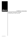
Installation Instructions
Dishwasher
External Blower Assembly for
Electrolux Retractable Ventilation Systems
E30DD75ESS
E36DD75ESS
E46DD75ESS
E48DD75ESS
5995433678
2 Safety
IMPORTANT SAFETY INSTRUCTIONS
Safety Precautions
Do not attempt to install or operate your unit until you have read the safety
precautions in this manual. Safety items throughout this manual are labeled with a
Warning or Caution based on the risk type.
Definitions
This is the safety alert symbol. It is used to alert you to potential personal injury
hazards. Obey all safety messages that follow this symbol to avoid possible injury
or death.
!
!
WARNING
WARNING indicates a potentially hazardous situation which, if not avoided, could
result in death or serious injury.
!
CA
UTION
CAUTION
CAUTION indicates a potentially hazardous situation which, if not avoided, may result
in minor or moderate injury.
CA
UTION
CAUTION
CAUTION used without the safety alert symbol indicates a potentially hazardous
situation which, if not avoided, may result in property damage.
IMPOR
TANT
IMPORT
Indicates installation, operation or maintenance information which is important but
not hazard related.
Safety
SAFETY PRECAUTIONS
!
WARNING
• To reduce the risk of fire, electric shock, or injury to persons, observe the following:
a) Installation work and electrical wiring must be done by qualified person(s) in
accordance with all applicable codes and standards, including fire-rated
construction.
b) Sufficient air is needed for proper combustion and exhausting of gases
through the flue (chimney) of fuel burning equipment to prevent back
drafting. Follow the heating equipment manufacturer’s guidelines and safety
standards such as those published by the National Fire Protection
Association (NFPA), and the American Society for Heating, Refrigeration and
Air Conditioning Engineers (ASHRAE), and the local code authorities.
c) When cutting or drilling into wall or ceiling, do not damage electrical wiring
and other hidden utilities.
d) Ducted fans must always be vented outdoors.
e) Use this unit only in the manner intended by the manufacturer. If you have
questions, contact the manufacturer.
f) Before servicing or cleaning unit, switch power off at service panel and lock
the service disconnecting means to prevent power from being switched on
accidentally. When the service disconnecting means cannot be locked,
securely fasten a prominent warning device, such as a tag, to the service
panel.
g) Blower must not be installed in a ceiling thermally insulated to a value
greater than R40.
h) Blower must not be installed in furnace ductwork.
• To reduce the risk of fire, use only metal ductwork.
3
4 Safety
SAFETY PRECAUTIONS
!
WARNING
• To reduce the risk of a range top grease fire:
a) Never leave surface units unattended at high settings. Boilovers cause
smoking and greasy spillovers that may ignite. Heat oils slowly on low or
medium settings.
b) Always turn hood ON when cooking at high heat or when flambeing food (i.e.
Crepes Suzette, Cherries Jubilee, Peppercorn Beef Flambe’).
c) Clean ventilating fans frequently. Grease should not be allowed to accumulate
on fan or filter.
d) Use proper pan size. Always use cookware appropriate for the size of the
surface element.
• To reduce the risk of injury to persons in the event of a range top grease fire,
observe the following:
a) SMOTHER FLAMES with a close-fitting lid, cookie sheet, or metal tray, then
turn off the burner. BE CAREFUL TO PREVENT BURNS. If the flames do not go
out immediately, EVACUATE AND CALL THE FIRE DEPARTMENT.
b) NEVER PICK UP A FLAMING PAN - You may be burned.
c) DO NOT USE WATER, including wet dishcloths or towels - a violent steam
explosion will result.
d) Use an extinguisher ONLY if:
1) You know you have a Class ABC extinguisher, and you already know how to
operate it.
2) The fire is small and contained in the area where it started.
3) The fire department is being called.
4) You can fight the fire with your back to an exit.
Safety
SAFETY PRECAUTIONS
!
CA
UTION
CAUTION
• For general ventilating use only. Do not use to exhaust hazardous or explosive
materials and vapors.
• To reduce risk of fire and to properly exhaust air, be sure to duct air outside – Do
not vent exhaust air into spaces within walls or ceilings or into attics, crawl spaces
or garages.
• This blower assembly is approved for use with the following Electrolux retractable
ventilation systems: E30DD75ESS, E36DD75ESS, E46DD75ESS and E48DD75ESS
only. Use of this blower assembly with any other product or in any other
configuration is hazardous and voids the product warranty.
NO
TES
NOTES
• Consult a licensed ventilation contractor or qualified technician for proper
installation of exhaust ducting.
• Locate the cooking area for minimum cross drafts – away from doors and windows,
when possible.
• Ducts must be of adequate size and duct runs should be as short and straight as
possible. Where turns are necessary, keep turning radius as large and smooth as
possible.
• The ducting must be air tight. Use a minimum of 2 sheet metal screws at every duct
joint. Then, seal the duct joints with a high quality duct tape.
• In duct runs less than 10 equivalent straight feet, the remote blower may interfere
with the cooktop burner performance due to the high volume of air moved. An
adjustable damper (not included) should be installed in the ducting system. The
damper can be adjusted so that proper ventilation and cooktop burner
performance is achieved.
• Installation of duct work should be carefully planned if it is to go under a concrete
slab floor. The duct trench should be boxed to prevent collapse from the wet
cement. Be sure to allow room to run the electrical wiring and conduit.
5
6 Finding Information
READ AND SAVE THESE INSTRUCTIONS
Attach your sales
receipt to this
page for future
reference.
NO
TE
NOTE
Installer: Leave instructions with owner.
Owner: Read your Retractable Ventilation System Use & Care Manual. It contains
important safety information for operating this appliance. It also has many suggestions
for getting the best results from your retractable ventilation system.
Read all instructions before installing the retractable vent.
For your safety, please read and observe all safety instructions. This guide will help
you anticipate all installation connections.
QUESTIONS?
For toll-free telephone support in the U.S. and Canada:
1-877- 4ELECTROLUX (1-877-435-3287)
For online support and Internet product information:
www.electroluxusa.com
©2005 Electrolux Home Products, Inc.
Post Office Box 212378, Augusta, Georgia 30917, USA
All rights reserved. Printed in the USA
Finding Information
TABLE OF CONTENTS
Safety ................................................................... 2
Important Safety Instructions .............................. 2
Safety Precautions ............................................. 3
Finding Information ........................................... 6
Please Read And Save This Guide ................... 6
Questions .......................................................... 6
Table of Contents ............................................... 7
Planning for Installation .................................... 8
Installation Planning ........................................... 8
Specifications and Dimensions ........................... 8
Making the Electrical Connection ................... 13
Blower Installation ........................................... 14
Verifying Operation .......................................... 14
7
8 Planning for Installation
INSTALLATION PLANNING
A qualified technician must complete the installation of this appliance.
Carefully check the location where the remote blower is to be installed. The remote
blower should be placed for convenient access. Make certain that electrical power
can be provided in the selected location.
Plan the installation so that all minimum clearances are met or exceeded.
Dimensions shown provide minimum clearances, unless otherwise noted.
SPECIFICATIONS AND DIMENSIONS
NO
TE
NOTE
All dimensional tolerances are + 1/16”, - 0” unless otherwise stated.
Before commencing installation, remove the top cover of the remote blower. Check to
see if the blower wheel turns freely. Do not replace the top cover until the installation is
complete.
Blower Overall Dimensions
Top View
Blower Overall Dimensions
Side View
26" (660mm)
24" (610mm)
12 11/16" (322mm)
9 1/2"
(241mm)
11 1/2"
(292mm)
9 9/16"
(243mm)
3 1/2"
(89mm)
CL
CL
Power Supply
Conduit
Location
12 1/4"
(311mm)
10"
(254mm)
CL
31 1/2"
(800mm)
33 1/2"
(851mm)
Cutout
Location
Intake Collar
Discharge
Figure 1
Mounting
Flange
Intake Collar
Discharge
Figure 2
Planning for Installation
Blower Overall Dimensions
Model
No.
Overall Chassis
Width
Overall Chassis
Height
5304444802
26” (660mm)
9 9/16” (243mm)
Overall Chassis
Length
33 1/2” (851mm)
Duct
Diameter
10” (254mm)
Blower Specifications
Model
No.
5304444802
Electrical
Supply
Requirements
Maximum
Duct
Length
Refer to
Max. 60
Ventilator
Equivalent
Specifications Straight Feet
Total
Connected
Load
Fan
Rating*
Approx.
Shipping
Weight
0.3kW (3A)
1600
CFM
55 lbs.
* The CFM Fan Rating is valued at 0” (zero-inch) static pressure.
Finish
Galvanized
(may be painted)
9
10 Planning for Installation
NO
TE
NOTE
The blower must be sealed between the roof or wall and the underside of the flange with
mastic to prevent leaks. For installation on a flat roof, or a roof with a pitch of less than
2:12, install the blower on a curb as shown below. Position the curb on flat roofs so that
the discharge (low) end points away from the prevailing wind.
Blower Flat Roof Installation
Blower Sloped Roof Installation
Flange
Roof Curb
REMP
Sealant
Air
Discharge
Sealant
45° Adjustable
Elbow
Round Duct
Figure 3
Figure 4
Blower Sloped Roof Installation
Dimensions
2"
(51mm)
33 1/2"
(851mm)
6"
(152mm)
2"
(51mm)
26"
(660mm)
30 1/2"
(776mm)
Figure 5
Planning for Installation
11
Blower Roof Installation
Side View
Blower
Air
Discharge
45° Adjustable
Elbow
3 1/4" x 10" to
Round
Transistion
Cooktop
AIR
3 1/4" x 10"
90° Elbow
3 1/4" x 10"
90° Elbow
Figure 6
12 Making the Electrical Connection
ELECTRICAL CONNECTION
!
WARNING
Ensure that the power supply is disconnected before proceeding.
Verify that the power supply matches the ratings found on the appliance data
plate before proceeding.
The complete appliance must be properly grounded at all times when electrical
power is applied.
Do not ground the appliance with the neutral (white) house supply wire. A
separate ground wire must be utilized.
If aluminum house supply wiring is used, splice the appliance copper wires to
the aluminum house wiring with special connectors designed and agencycertified for this purpose. Follow the connector manufacturer’s recommended
procedure carefully. Improper connection can result in a fire hazard.
Failure to complete electrical connections properly may result in a damaged or
non-functional system. Follow the wiring diagrams carefully to ensure a proper
installation.
It is the owner’s responsibility to ensure that a qualified electrician performs the
electrical connection of this appliance. The electrical installation, including
minimum supply wire size, must comply with the latest revision of the National
Electric Code ANSI/NFPA 70* and local codes and ordinances.
A copy of this standard may be obtained from:
National Fire Protection Association
1 Batterymarch Park
Quincy, Massachusetts 02269-9101
NO
TE
NOTE
Make all electrical connections between the vent and blowers, then connect
power to the vent as per the wiring diagram shown.
Use wire nuts and electrical tape to secure all wiring connections at the blowers.
13
Installing the Blower
BLOWER INSTALLATION
Mount the blower to the wall or roof using screws,
through mounting trim flange.
Wiring of Retractable Ventilation System
(E30DD75ESS, E36DD75ESS, E46DD75ESS
and E48DD75ESS)
Verifying Proper Operation
1
2
3
Temporarily re-install the remote blower
cover, using 2 screws per side).
Turn on the power supply at the circuit
breaker.
Refer to the Retractable Vent Installation
Instructions for further instructions on
verifying the proper operation.
Vent
Gnd
GRN
GRN
Gnd
GRN
WHT
N1
WHT
BLK
L1
BLK
N2
WHT
L2
BLK
120VAC, 60Hz, 15A
Supply power from
dedicated circuit breaker
Blower
5304444802
L2
BLK
N2
WHT
Gnd
GRN
Figure 7
IMPOR
TANT
IMPORT
If the remote blower does not operate properly, follow these troubleshooting steps:
1. Verify that power is being supplied to the Retractable Vent and the remote
blower.
2. Check the electrical connections to ensure that the installation has been
completed correctly.
3. Repeat the above test.
4. If the appliance still does not work, contact Electrolux at 1-877-4Electrolux. Do
not attempt to repair the appliance yourself. Electrolux is not responsible for
service required to correct a faulty installation.
1-877-4Electrolux
www.electroluxusa.com
www.electroluxca.com