1
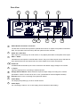
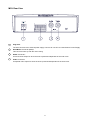
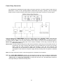
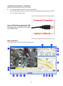
MDR-304A Digital Video Recorder Instruction Manual Stock code: 2919A SAFETY PRECAUTIONS All the following safety and operation instructions which will prevent harm or damage to the operator or other persons should be read before the unit is operated. INFORMATION This equipment has been tested and found to comply with the limits for a Class A digital device, pursuant to Part 15 of the FCC Rules. These limits are designed to provide reasonable protection against harmful interference when the equipment is operated in a commercial environment. This equipment generates, uses, and can radiate radio frequency energy and, if not installed and used in accordance with the instruction manual, may cause harmful interference to radio communications. Operation of this equipment in a residential area is likely to cause harmful interference in which case the user will be required to correct the interference at his own expense. WARNING ! To reduce the risk of fire or electric shock, do not expose this appliance to rain or moisture. ! Do not block ventilation openings. ! Do not place anything on top of the unit that might spill or fall into it. ! Do not attempt to service this unit yourself as opening or removing covers may expose you to dangerous voltage or other hazards. Please refer all servicing to qualified service personnel. ! Do not use liquid cleaners or aerosols for cleaning. ! This installation should be made by a qualified service person and should conform to all local codes. To prevent fire or electric shock, do not overload wall outlets or extension cords. This unit must be grounded to reduce the risk of electric shock hazard. CAUTION ! Danger of explosion if battery( RTC Battery ) is incorrectly replaced. Replace only with the same or equivalent type recommended by the manufacturer. Dispose of used batteries according to the manufacturer’s instructions. ! Risk of explosion if replaced by an incorrect type. Dispose of used batteries according to the instructions. 1 1. INTRODUCTION .....................................3 Manual Recording ....................................... 27 Product Features............................................3 Playback Operations ................................... 27 Accessories....................................................4 Normal Playback ......................................... 27 Front View ......................................................6 Fast Forward/Backward .............................. 27 Rear View.......................................................8 Slow Forward/Reverse................................ 27 MCU Rear View .............................................9 Play back picture-by-picture........................ 28 Power Delay Connection .............................10 Search Operations ...................................... 28 The Power Connector ..................................11 FULL LIST Search....................................... 28 I/O Port.........................................................13 ALARM LIST Search ................................... 28 I/O Connection .............................................14 TIME Search ............................................... 28 Voltage Management ...................................15 THUMBNAIL Search ................................... 29 2. INSTALLATION .....................................16 Backup Operations...................................... 30 System Information and Channel Selection.16 SD Card Backup Operations....................... 30 System information ......................................16 Key Lock Operation..................................... 31 Channel Selection ........................................17 5. MISCELLANEOUS ................................ 32 Updating System Software ..........................17 System Default ............................................ 32 The G-sensor ...............................................17 O.S.D Messages ......................................... 33 3. SET UP................................................ 18 Time Index Table ......................................... 34 Configuring Recording Settings ...................18 Specifications .............................................. 35 Alarm Recording ..........................................19 HDD Viewer............................................... 36 Externally Triggered Recording....................19 Introduction.................................................. 36 Menu ............................................................19 Installation Instructions - Software .............. 37 REC Setting .................................................20 Installation Instructions - Hardware............. 40 Alarm ............................................................21 Basic Operation........................................... 40 CLOCK/ TITLE Settings ...............................23 Advanced Operation .................................. 43 COMMUNICATION Settings ........................23 Save a snapshot to a PC ............................ 43 DISK Settings...............................................24 Save a video file to a PC............................. 43 SYSTEM Settings ........................................24 Read the CSV report................................... 44 Alarm and Motion Settings...........................26 APPENDIX 1. –Table of LOG Message ..... 46 4. OPERATIONS .....................................27 Recording.....................................................27 2 1. INTRODUCTION Product Features Quad-based operation: real-time operation and playback (30 FPS/ per channel). MPEG4 compression with resolution up to 720X480 (NTSC) / 720X576 (PAL). 4x Elite/Extreme connectors for AV inputs. 4 camera audio inputs, 2 auxiliary audio inputs, 1 audio output (1 channel record). Pre-alarm image recording. USB interface showing video records on a Laptop/PC. GPIO: 4 inputs and 2 outputs. Operating temperature: 0℃to 50℃. Time-lapse and real-time recording. Refresh rate up to 30 IPS (25 IPS for PAL). Image quality selectable at 4 different levels for recording. Alarm recording mode. Quick search by time, alarm, event, and recording list. Fast and slow playback of video recorded at various speeds. Single-picture playback. On-screen setup menu, title and system timer. Password protection. Disk-full warning. Operation-status record log. Automatic detection of voltage. Built-in SD card slot for copying images to an SD card. Watermark. Window Division. Vibration and mechanical shock protection. By taking advantage of the optional G-Sensor, the MDR-304A will register and record X, Y & Z impact data in the event of an accident and can be used as an alarm trigger. If the voltage is less than 10.4/17.5 volts, the MDR-304A recorder will display a message “Low Voltage” and then automatically power off after beeping for 3 -5 seconds. 3 Accessories The kit contains the following items: Sub-System Qty 1 Sub-system Description MCU-304A-XXX (Mobile Caddy Unit) 1 MDR-304A-DS (Docking Station) (2798A) 1 AVM-304 (Anti-Shock/Vibration Mounting) (2917) 1 MDR-304A-MAN (Instruction Manual) (2919A) 1 CD-304A-01 (Installation CD) (2920A) 1 PV-12 (12V MCU Power Supply) (3973) 1 MDR-304A-PC (Power Cable) (3972) 4 1 USB-001 (USB Lead) (2918) 1 MDR-304A-TRIG (Trigger Cable) (2997A) 1 MDR-304-SK (2x Security Keys) (2994) 1 MDR-304-STS (4x Self Tapping Screws) (2995) Notes: The MDR-304A should not be operated without the anti-shock/vibration mounting unit. Stock codes that are underlined are not available separately. 5 Front View 1 PLAY mode.) SETUP button: Press this to enter the setup menu. Press 2 5 again to exit the setup mode. In a playback display, press this to Left/ Right/ Up/ Down (CH1/ CH2/ CH4/ freeze the display. During the freeze, CH3) buttons: press to display one frame of a picture at In the menu setup mode / search mode, a time in the forward direction (A light press the four buttons on the dial to glows red in the PAUSE mode.) highlight desired items in the menu 3 6 FF button: setup mode. In the live / play mode, Press this to play a recorded video in the press the four buttons on the dial to forward direction at a speed that's faster select a channel for display. or slower than the recorded speed in the REW button: play mode Press this to play a recorded video in the 4 PAUSE button: 7 STOP button: reverse direction at a speed that's faster Press to stop playing back a recorded or slower than the recorded speed in the video. (A light glows red in the STOP play mode. mode.) PLAY button: 8 REC button: Press to play back a recorded video from Push to start recording video into a hard the hard disk. (A light glows red in the disk while in the live display mode. (A light 6 glows red in the REC mode.) 9 MCU Lock: This key lock secures the MCU with the hard disk in place. When you lock it in, it powers on the device. When you unlock this key and take out the inner case, the power turns off automatically. 10 SEARCH button: Press to enter the search mode to access the recorded video. 11 DISPLAY button: Press to show the system operation status on the screen. 12 Enter / (Quad) button: Press to enter a selected item and save the setting in the menu setup mode. In the live/ play mode, use this button to show a quad display. 13 SD CARD slot: This is used for system software updating, saving and loading of user settings as well as the saving of JPEG still images or short AVI clips. 14 USB port: Allows the recorder to be connected to a PC or laptop for viewing of recorded files using HDD Viewer Software. Also can be used to quickly transfer larger quiantities of raw video data for storage onto a PC or laptop Hard Disc when converted to FAT32 format. HDD viewer software is still needed to view these files. 7 Rear View 2 1 4 3 2 1 GPS Remote AUX1 Audio Out Video Out 5 3 4 Camera In AUX2 I/O RS-232 12V 9V 6V IN1 IN2 IN3 IN4 G-SENSOR OUT1 OUT2 6 1 7 8 Power Delay 30A MAX 9 +24V +12V ACC 10 GPS & Remote Controller Connector: The left side connector links up with the optional GPS receiver to capture local position information data. The right side connector links up with the optional remote controller. 2 Audio Out / Video Out: Main output for connecting to an LCD monitor, or any display with Audio & Composite Video inputs. 3 AUX 1 / AUX 2: Individual line level inputs for external audio sources. Only one of these inputs can be selected at a time. Note that are line level inputs and may not be suitable for low level microphones. 4 5 Camera In: Combined video and audio inputs. These connectors also deliver supply voltage to the camera. 6 I / O port: Input and output port for connecting to external devices. 7 Voltage Selector Switch: Please select the required output voltage according to the camera specification. There is a choice of 6V, 9V or 12V. (12V Should be used for Brigade cameras) 8 G Sensor port: For the connecting of an optional G Sensor. 9 Power Delay: For delaying the powering up of other vehicle devices. 10 Power Input: For connecting to either a 12V or 24V supply (These should be fused suitably). 8 MCU Rear View 1 Plug Inlet: The inlet connects to an external power supply. Connect to 12V DC UL Listed Class 2 Power Supply. 2 Hard Metric Connector (Male): This connector links up with the outer casing. 3 Audio Connector: Line level audio output for when the host is powered independent of the outer case. 4 Video Connector: Composite video output for when the host is powered independent of the outer case. 9 Power Delay Connection The diagram here illustrates the power delay connection structure. If a device needs to work with our MDR-304A, it needs to start operating after our MDR-304A has begun operating. See the diagram below to help you with the mobile vehicle video recorder's power delay connector on its rear panel. Enter the MDR-304A's "MAIN MENU" page and choose the third item, "CLOCK / TITLE". Now enter the "CLOCK / TITLE" page, and you will see two items, "DELAY ON" and "DELAY OFF". For both these items, the default setting is "OFF". You can set the delay time of the relay by choosing one of the following options. DELAY ON: This entry sets the delay time of the function activation of the relay connector after the MDR-304A powers up. DELAY OFF: This entry sets the delay time of the function activation of the relay connector after the ACC is powered off. The relay connector will function as per the delay time you set by your chosen option. After the relay connector's delay time duration is over, the relay connector will automatically turn off, followed by the MDR-304A. (The MDR-304A which is connected with the cigar-lighter of the vehicle for its power supply will stop working when the ignition is switched off.) Note: The relay connector’s electric current range goes to a maximum of 30 amperes. Note: Our "POST REC DURATION" function also sets the time as per any of the six options available after the ACC has been turned off. Please always be mindful of the fact that, if the time duration set for either "DELAY OFF" or "POST REC DURATION" is longer than the other one, the MDR-304A will wait for the longer setting to end before shutting down. 10 The Power Connector Connect either pin 2 (24V) or pin 3 (12V) depending on vehicle voltage. Pin connections with the ignition key 12V: This method of connection is the most accepted and is recommended for permanent vehicle installations where either the post record duration 24V: or motion detection features will be used. (12/24V inputs should be fused). 11 Pin connections without the ignition key. 24V: This method of connectivity is recomended for temporary installations only. Post record or motion detection is not possible. 12 I/O Port This figure is seen from the rear view. 1. I/O IN1 (INPUT): This is an alarm input which can be programmed in the menu system to Normally Open or Normally Closed. 2. I/O IN2 (INPUT): same as above. 3. I/O IN3 (INPUT): same as above. 4. I/O IN4 (INPUT): same as above. 5. GND: Ground Contact. 6. GND: Ground Contact. 7. I/O OUT1 (OUTPUT): This is a “normally open” switched ground output that becomes closed when INPUTS 1-4 go active. Connect this to the negative terminal of an external devices such as a buzzer or light. Maximum load current is 600mA. 8. I/O OUT2 (OUTPUT): Same as above. 13 I/O Connection ALARM: In the "MAIN MENU" page, click "ALARM" to enter the "ALARM" page and then go to the "I/O CONNECTION" item which has three options, "ALARM", "VEHICLE SIGNAL T" and “VEHICLE SIGNAL A”. If you choose "ALARM" pins 1, 2 and 3 will become alarm input triggers which can receive a 12v-24v trigger voltage. Pin 4 is a "Reset" trigger; pins 5 and 6 are permanent ground contacts; pin 7 and 8 are normally open switched grounds for connecting to external devices like buzzers or lights. Alarm Operation must be set to ON in the Alarm Setting Menu. VEHICLE SIGNAL T: In the "MAIN MENU" page, click "ALARM" to enter the "ALARM" page and then go to the "I/O CONNECTION" item which has three options, "ALARM", "VEHICLE SIGNAL T" and “VEHICLE SIGNAL A”. If you choose "VEHICLE SIGNAL T” pins 1, 2, 3 & 4 will become input triggers which can receive a 12v-24v trigger voltage. These can be connected to left or right indicators, brake lights or other 12v–24v vehicle signal lines. The time and duration of these signals will be imprinted as a marker on the recording as T1, T2, T3, T4. Pins 5 and 6 are ground contacts. Pin 7 and 8 are not used. VEHICLE SIGNAL A: If you select option "VEHICLE SIGNAL A", pins 1, 2, 3 & 4 will become 12v-24v input triggers for switching the recorders video output from a quad image to individual full screen images for each cameras when required. One practical application would be to connect the appropriate trigger for the reversing camera to the reverse light circuit so when the driver engages reverse the display will show the reverse camera as a full image rather than one of 4 smaller quad images. Pins 5 and 6 are ground contacts; pin 7 and 8 are not used. (Indicator triggers will require TS-001ECU). 14 Voltage Management Voltage detection while the MDR-304A is working: You can display the system-setting information after you press the "DISPLAY" button on the front panel. On this screen you can see the battery voltage icons. Please consult the above diagram to know the battery voltage status. Note: The MDR-304A will not beep when the Buzzer function is disabled. Warning: If the supply voltage exceeds 36 volts the recorder will be damaged and the warranty may be void. 15 2. INSTALLATION System Information and Channel Selection Figure 2.3 A. System information HD1 : 163G 94.0 HR QUALITY : BEST You can display system settings information as RATE : 20 F/S shown in Figure 2.3 A by pressing the Display 58 K button. In playback mode, recorded video information is displayed. In the live or recording mode, current displayed. recording Each Display button information sequential press of HD 1 is SIZE 163G REC 10.0% PLAY 0.1 % the displays a different message X: Y: Z: G: detailed in the following example. By default, the unit displays time, date, and an indicating 0 0 1.0 0.0 bar of capacity status on a monitor as shown. 05 / 10 / 2011 15:12:22 Default Display CH1 PAL x ( HD1: 163G ): Total capacity of installed hard disk, 163 GB. CH2 ( 94.0 HR ): Total 94.0 hours recording time available. ( ): Alarm record activated. ( QUALITY: BEST ): Record quality setting, BEST. CH3 CH4 ( NTSC ): NTSC system. ( RATE 20 F/S ): Record speed setting, 20 frames/sec. 01/01/2006 12:00:00 ( ): The current voltage status. CH1, CH2, CH3, CH4 are titles for each ( channel, changeable in the Setup menu. ( 58K ): The image file size. ): Audio function activated. ( 163G ): The capacity of the installed hard disk. ( REC ): Percentage of system recording position. Capacity Status : ( Capacity Used ) ( Capacity Remaining ( PLAY ): Percentage of the system playback position. ) ( ( 05- 10-2011 (Date) ): External signal. x ): Cannot operate now. For example, press the SETUP, SEARCH, REW and FF buttons during 12:00:00 the recording mode, and this icon will appear. (Time) (X, Y, Z, G ): The value “G” is only used when the Pressing the Display button once, will display MDR-304A connects with a G sensor, which can the figure 2.3A. Press the Display button again; detect the vehicle acceleration force or G force. the unit will not display any OSD message. Press the button one more time to go back to the default display. 16 restart automatically. (If you have already followed Channel Selection procedures 1 ~ 5 and the unit is still unable to turn on, ) then please first check if the SD card you are using buttons are used to select single video channels is functioning and the file is intact. And then start and the quad mode. The following table shows the procedures 1 ~ 5 all over again.) The CH1, CH2, CH3, CH4, and Quad ( functions under a different mode. Mode Split Key 4 CH Quad 6. Verify the version of the system software. ! Caution: Result Display 1. Before carrying out the updating procedures, please ( ensure the SD card is working and the file of the ) CH1/ CH2/ system software is intact. ( Single 2. Don’t interrupt the process while the unit is updating channel ) CH3/ itself, as this will cause the unit to crash. CH4 3 CH 3. Contact Brigade Electronics for latest software Quad version. ( Live / ) Record / CH1/ Playback CH2/ The G-sensor ( Single channel ) When installing the G sensor it is important to correctly orientate it as shown in the diagram below.When stationary the G sensor measure 0 g in the X axis, 0 g in the Y axis, 1 g in the Z axis. The total G value will be approximately “0” when a vehicle remains stationary or moves at a constant speed. CH3 2 CH Quad ( ) CH1/ CH2/ ( Single channel ) Up Updating System Software Left To safely update the system software: Forward 1. Turn off the MDR-304A. 2. Insert the SD card into the built-in SD slot. 3. Turn on the MDR-304A. 4. The MDR-304A sounds a tone and displays the message “ XXXXXX BYTES READ”. Now the MDR-304A is updating the system software, which will take approximately 90 seconds to process. 5. The MDR-304A displays the message “PLEASE REMOVE SD CARD”. The process is complete. Please remove the SD card, and the MDR-304A will 17 RMN V1.2 3. SET UP NOTE: Configuring Recording Settings Recording times are estimated in the tables below. For the actual available recording time of Recording time will vary depending on the image a recording configuration, please refer to the size, recording rate, and the capacity of the system information of the MDR-304A. (Please hard-disk drive (HDD). The table below shows the refer information for more details.) possible recording times per 80GB at different refresh rates and image quality. Possible Recording Time per 500GB ( hour ) Image BEST 205.6 249.7 464.8 876.0 Quality HIGH 249.7 321.9 561.5 1137.9 STANDARD 321.9 464.8 786.8 1632.0 464.8 604.6 1137.9 2921.9 NTSC 30 / PAL 25 NTSC 15 / PAL12.5 6 2 BASIC Refresh Rate (FPS) 18 Alarm Recording Menu (1) Press the SETUP button to enter the MAIN Press the Setup button to access the setup menu. Once inside the menu system, the on-screen menu MENU. allows you to set up the key features of the unit. The (2) Select ALARM and press the Enter button functions of various buttons within the menu-setup to enter ALARM. mode are described in the paragraphs below. (3) Set the desired REC RATE, REC QUALITY, ALM TYPE, and ALM DURATION for use. If the audio function is required, set AUDIO to KEY FUNCTIONS ON. If pre-alarm recording is required, set Setup button: PRE-ALARM to ON. Press to enter the setup menu. Press again to exit (4) To activate/deactivate the alarm recording, the setup mode. set ALM OPERATION to ON/ OFF. “^” and “v” buttons: MAIN MENU Press to select the desired item or entry for setting. RECORD ALARM CLOCK/ TITLE COMMUNICATION DISK SYSTEM “<” and “>” buttons: Press to highlight the desired option or to select the GOTOALARMPAGE context for setting. ALARM SETTING ALM OPERATION REC RATE REC QUALITY AUDIO ALM TYPE ALM DURATION PRE-ALARM IO CONNECTION Enter button: : OFF : 15 F/S : BEST : OFF : NO : 30 SEC : OFF : ALARM Press to enter the selected item and to save the setting. MAIN PAGE Externally Triggered Recording By connecting the ALARM IN of ALARM I/O on the rear panel of the MDR-304A, you can activate / deactivate the alarm recording function of an MDR-304A. The file will be kept with a prefixed “A”. 19 REC Setting DISK FULL: This option determines the way to utilize This page allows you to set the recording rate storage media in case of a full disk. and recording quality, and enables you to REWRITE: When the hard disk is full, the device continue recording when the disk is full. continues recording by displacing the old data. STOP: When the hard -disk is full, the device MAIN MENU will stop recording. RECORD ALARM CLOCK/ TITLE COMMUNICATION DISK SYSTEM AUDIO: OFF: Disables AUDIO recording. GOTO REC PAGE ON: Enables AUDIO recording. NOTE: The audio function can only be activated REC SETTING REC RATE : REC QUALITY : DISK FULL : AUDIO : TIME STAMP : POST-REC DURATION: SPLIT : A/V SOURCE : in the following refresh rates in NTSC(PAL): 30(25), 15(12.5), 6(6) and 2(2) frames/sec. 30 F/S BEST REWRITE ON ON OFF 4CH SET TIME STAMP: Select “ON” to add a timestamp to the recording files. Select “OFF” to deactivate this function. MAIN PAGE POST-REC DURATION: After the ACC is powered off (ACC OFF), the REC RATE: MDR-304A will continue recording for the time This option is for adjusting the number of pictures which is set in the "POST-REC DURATION" recorded very second. time. This option determines the duration of the For an NTSC unit, there are 4 different recording post-recording time after the ACC is turned off. rates you can select from: 30F/S (30 frames per There are 9 options you can select from: OFF, 1 MIN, 5 MIN, 10 MIN, 30 MIN, 60 MIN, 90 MIN, second), 15F/S, 6F/S, and 2F/S. 120 MIN and NON STOP. For a PAL unit, there are 4 different recording OFF: The recording will stop automatically when rates you can select from: 25F/S (20 frame per the vehicle motor is turned off. second), 12.5F/S, 6F/S and 2F/S. NON-STOP: This option allows for continuous recording after a vehicle has been switched off. However, this depends on the amount of battery power available, as it can run only as long as REC QUALITY: there is power. Enough power will be left You can select from 4 levels of image quality: BEST, HIGH, STANDARD, and untapped by this option to turn the vehicle engine BASIC. on the next time the user starts it. Selecting the BEST image for use provides higher-resolution recorded images, Note: If the voltage is less than 10.4 volts, the battery is in the "Too low" mode", and the MDR-304A will automatically power off and there may be a problem in starting the engine. and normally takes up more storage space than a HIGH, STANDARD or BASIC image does. 20 range from "00" (mute) to "10" (full). SPLIT: This option determines the layout of the screen. Alarm You can select from 4CH, 3CH, and 2CH. The Recording program settings for when an alarm resulting layout on the screen will be as follows. input is activated. The device will record at these settings for as long as the alarm input is 4 CH: CH1 activated. CH2 MAIN MENU CH3 RECORD ALARM CLOCK/ TITLE COMMUNICATION DISK SYSTEM CH4 3 CH: GOTO ALARM PAGE 01/01/2006 12:00:00 ALARM SETTING CH1 CH2 ALM OPERATION REC RATE REC QUALITY AUDIO ALM TYPE ALM DURATION PRE-ALARM CH3 IO CONNECTION MOTION SETTING 01/01/2006 12:00:00 MAIN PAGE 2 CH: ALM OPERATION: ON: The device activates the alarm recording when it detects an alarm input. OFF: The device ignores the alarm signal when it detects an alarm input. CH1 CH2 REC RATE: Choose the number of pictures recorded every second when an alarm input is activated. For an NTSC unit, there are 5 different recording speeds you can select from: 30F/S (30 frames per second), 15F/S, 6F/S, 2F/S, and REMAIN. For a PAL unit, there are 5 different recording speeds you can select from: 25F/S (25 frames per second), 12.5F/S, 6F/S, 2F/S, and REMAIN. If you select REMAIN, the device will record images at the same speed as set on the REC page. REC QUALITY: Choose the image quality to be recorded when an alarm input occurs. There are 4 levels of image quality to choose from: BEST, HIGH, STANDARD, and BASIC. The table below shows the level of image quality with the corresponding compression ratio and image size. 01/01/2006 12:00:00 A/V SOURCE: A/V SOURCE CH2 CH3 CH1 CH4 CAMERA1 CAMERA2 CAMERA3 CAMERA4 AUDIO 1 AUX 1 LIVE OUTPUT VOL. 10 <> : OFF : 15 F/S : BEST : OFF : NO : 30 SEC : OFF : ALARM MOVE ^v CHANGE This page allows you to configure the video output and the audio source from the auxillary or one of the camera inputs. Select which view you require then position the cameras accordingly. LIVE OUTPUT VOL.: This item determines the output volume levels in the live mode. The options 21 REC Quality Image Size Best High Standard Basic 60KB 50KB 40KB 32KB NOTE: If the device is already in the recording mode before an alarm occurs, the pre-alarm recording will not take effect. I/O CONNECTION: Can be connected to a trigger/alarm sensor which is for the setting of the I/O connections. There are three options: AUDIO: OFF: Disables the AUDIO recording. ON: Enables the AUDIO recording. NOTE: The audio function can only be activated in ALARM: Sets the 4 inputs of the I/O connection as ALM1/ ALM2/ ALM3/ according to…..RESET. The Alarm signals are used to trigger the alarm recording (3.2.2). the following refresh rates in NTSC(PAL): 30(25), 15(12.5), 6(6) and 2(2) frames/sec. ALM TYPE: Choose a type of alarm input corresponding to the sensor signal in use. NO: Normally Open. This is to be used with the type of alarm sensor whose contact remains open in normal conditions and closes in case of activation. NC: Normally Closed. This is to be used with the type of alarm sensor whose contact remains closed in normal conditions and opens in case of activation. VEHICLE SIGNAL T: Sets the 4 inputs of the I/O connection as T1/ T2/ T3/ T4 according to the user’s definition. For example, if the user gives the definition of “T1” as “rear passenger door open”, “T1” is displayed on the screen and imprinted onto the recording. VEHICLE SIGNAL A: Sets the inputs of the I/O connection to full screen displays for CH1/ CH2/ CH3 / CH4. When each input is triggered the corresponding channel will be displayed as a single full-screen image on the display . ALM DURATION: You can select one of the six following options: 0 SEC, 30SEC, 1 MIN, 5 MIN, 10 MIN, and NON-STOP. D uration Set ting MOTION SETTING: Motion detection is only active in the mode “ACC OFF”. When motion detection is enabled, post-record is disabled and the MDR-304A will only start recording when motion has been detected. The duration of recording will depend on the "ALM DURATION" setting. The length of time the MDR-304A will remain in a state of “watch” will depend on the “Post Record” setting. Alar m r ecor ding D uration Alar m activated N on-Stop Alar m deactivated Alar m r ecor ding MOTION SETTING CH1 CH2 CH3 CH4 SENSITIVITY D uration Alar m activated Alar m deactivated R eset PRE- ALARM: This option determines that images before an alarm occurs will be recorded in the hard-disk drive. When an alarm is triggered the device will record the image prior to the alarm for 5 seconds. ON: Enables this function. OFF: Disables this function. : ON : OFF : OFF : OFF :3 SET CH1 MOTION DETECTION ON/OFF 22 CLOCK/ TITLE Settings TITLE: Allows you to set the system time, the daylight Allows users to set the titles for each video source or camera, in live or recording mode; press the DISPLAY button to switch on the display status to show the titles. The maximum length for each title is 24 letters. saving time and the power delay time. Also allows users to set the titles for each video source or camera, in live or recording mode. MAIN MENU RECORD ALARM CLOCK/ TITLE COMMUNICATION DISK SYSTEM TITLE DEVICE CH1 CH2 CH3 CH4 GOTO CLOCK/ TIMER PAGE [ DVR [ FRONT [ RIGHT [ BACK [ LEFT ] ] ] ] ] C L O C K / T IT L E CLO CK D AY L IG H T S AV IN G T IT L E D E L AY O N D E L AY O F F : : : : : SET O FF SET O FF O FF TO MOVE TO CHANGE OPTIONAL RELAY Located on the rear of the MDR-304A, can be used to make an electrical connection to supplementary device when the MDR-304A is powered up. The relay is normally open (NO). M A IN PA G E CLOCK: Allows users to set the system time and decide whether to start using the GPS time. DELAY ON ENERGISE OF THE RELAY: Adds a time delay before the relay is activated. The options are OFF, 0 SEC, 1 MIN, 5 MIN and 10 MIN NOTE: The clock data is retained for about 3 months after the 15-hour power supply is used up (in the Operation mode). DELAY ON DE-ENERGISE: Adds a time delay before the relay is deactivated. The options are OFF, 1 MIN, 5 MIN, 10 MIN, 60 MIN and NON STOP. DAYLIGHT SAVING Allows users to set the daylight saving time. OFF: Disables the daylight saving time. US: Daylight saving time begins at 2:00 a.m. on the first Sunday of April. The time reverts to standard time at 2:00 a.m. on the last Sunday of October. EUROPE: (Except the UK) Daylight saving time begins at 2:00 a.m. on the last Sunday of March. The time reverts to standard time at 2:00 a.m. on the last Sunday of October. UK: Daylight saving time begins at 1:00 a.m. on the last Sunday of March. The time reverts to standard time at 1:00 a.m. on the last Sunday of October. SET: This sets the beginning and the end of the daylight saving time. COMMUNICATION Settings M A IN M E N U RECORD A LA R M C LO C K / TITLE C O M M U N IC ATIO N D IS K S Y S TE M G O TO C O M M PA G E COMM SETTING COMM ID : 0.1 RS232 ENABLE : ON RS232 CONNECTION : GPS BAUD : 4800 GPS SPEED : Km/H GSENSOR SENCITIVITY : 0.8 MAIN PAGE 23 hard disk, so files can be transferred to and stored on a PC. HDD Viewer will be required to view these files. COMM ID: This function is disabled and not supported on the current MDR-304A. RS-232 ENABLE: This function is disabled and not supported on the current MDR-304A. RS-232 CONNECTION: This function is disabled and not supported on the current MDR-304A. SD FILE: This option determines the format in which to save important image files in an SD card. JPEG: Archives images in the JPEG format, to save a single picture in every file. AVI: Archives images in the AVI format, to save a sequence of images in a file, the maximum limit being 300 images for every file. You can stop recording whenever you want, and if you don’t, recording will automatically stop at the maximum of 300 images. BAUD: This entry selects the baud rate of the GPS Antenna (RS232 port). This should be left at 4800. GPS SPEED: Select either Km/H (kilometers per hour) or MPH (miles per hour). AUTO ERASE: There are two options. OFF: Disables the "AUTO ERASE" function. SET: Enables the "AUTO ERASE" function. Select "SET" and press the ENTER button to enter the "AUTO ERASE SETTING" page, where you can enable the settings to save data for storage for any period of time from 1 to 365 days. After the expiry of the time period you set, the data will be erased automatically. G-SENSOR SENSITIVITY: Increases or decreases the point where an alarm activated recording is triggered by the G-sensor. DISK Settings MAIN MENU RECORD ALARM CLOCK/ TITLE COMMUNICATION DISK SYSTEM SD REFORMAT: Allows you to clear out all the data in the SD Card. SYSTEM Settings GOTO DISK PAGE MAIN MENU RECORD ALARM CLOCK/ TITLE COMMUNICATION DISK SYSTEM DISK SETTING HD REFORMAT HD FAT32 SD FILE AUTO ERASE SD REFORMAT : HD1 : BUILD : JPEG : OFF : START GOTO SYSTEM PAGE SYSTEM OPERATION LOG OSD LANGUAGE MENU BACKGND BUZZER PASSWORD SETUP PWD DEFAULT SD SETUP VERSION MAIN PAGE HD REFORMAT: Allows you to clear out all the data in the hard-disk drive. You will be required to enter a pre-set password before clearing out the data. Enter the standard password “9999” if you haven’t set your individual password. HD 1: Clears out all the data stored in HD 1. MEIN PAGE HD FAT32: This function builds the FAT32 file system in the 24 : ENTER : ENGLISH :2 : OFF : SET : OFF : LOAD : SAVE : ENTER OPERATION LOG: between levels 1 and 3. The background color is This page is used for accessing the history of the used in the setup menu and search functions. operation status, setting the password, resuming BUZZER: factory default, and determining the menu display Enables or disables the embedded buzzer to background. sound a 2 seconds long tone to signal the following situations. SYSTEM MAIN MENU OPERATION LOG OSD LANGUAGE MENU BACKGND BUZZER PASSWORD SETUP PWD DEFAULT SD SETUP VERSION RECORD ALARM CLOCK/ TITLE COMMUNICATION DISK SYSTEM ON: Enables the buzzer. ENGLISH OFF: Disables the buzzer. Situation Alarm occurs Video loss occurs Disk is full Loading factory default Buzzer is set to ON Key lock function is enabled/disabled Powering on /off the mobile rack HDD MEIN PAGE GOTO SYSTEM PAGE SET OSD TO ENGLISH LOG 05/15/04 18:19:30 05/15/04 18:19:36 05/15/04 18:23:10 05/15/04 18:23:50 05/15/04 18:25:05 05/15/04 18:27:12 05/15/04 18:50:30 05/15/04 18:51:20 SYSTEM ON SYSTEM OFF SYSTEM ON RE STOP C V-LOSS PLAY STOP-P PASSWORD: Allows you to set a password to prevent any unauthorized re-formatting of the hard disk drive and to unlock the entire front panel button controls. The standard password is “9999”. OLD PASSWORD: Enter the pre-set password This log shows the history of the operation status (or the standard password if this is the in chronological order. What the following entries initial setting) to access the password represent is detailed in APPENDIX 1. setting system. NEW PASSWORD: Enter a 4-digit-number Note: When the log is full, the newly registered password of your choosing which will record of an operation will replace the existing replace the pre-set password (or the records starting with the oldest record. standard password of “9999”). Backup the operation status log: SETUP PWD: 1. Insert the SD card into the built-in SD slot of the When this option is on, the user must enter the unit. correct password before entering the setup menu. 2. Hold down the STOP and SETUP buttons ON: Enables password protection. simultaneously in the live mode. OFF: Disables password protection. 3. The MDR-304A displays the message “SAVE OK”. The process is complete. DEFAULT: 4. The operation status log will be saved into the This option allows you to reload the factory SD card (log.txt). default setting. Please note that the password cannot be changed in the factory default setting. OSD LANGUAGE (optional): Choose which language to use. SD SETUP: The MDR-304A offers a quick setup method by MENU BACKGND: There are 3 levels of background using an SD card. To set up a number of color MDR-304As with the same settings, simply save transparency you can choose from: level 1 is the desired settings from one MDR-304A onto totally transparent, level 3 is opaque, and level 2 is 25 an SD card, and then transfer these settings to any number of MDR-304A recorders. ACC IGNITION OFF: SAVE: Saves the whole setting to the SD 1. After the ACC is powered off (ACC OFF), the card. MDR-304A will record continuously for the time set LOAD: Loads the whole setting from the SD in the "POST-REC DURATION" time. If the user card. enables VERSION: both “ALM OPERATION” and the “MOTION DETECTION” functions the MDR-304A This item is in the setup menu: it shows the BIOS will not start recording until version, the software version and last updated motion alarm is triggered during the "POST-REC DURATION" date, and the rear board version. period. The length of recording will depend on the Alarm Duration setting. VERSION 2. Motion detection can only be activated in the SW : 1.21 DATE : Nov 10 2006 KEY : 1.00 REAR: 1.09 “ACC OFF” mode.. 3. Please take note that if the "POST-REC DURATION" time is over, the MDR-304A will stop recording even if the "ALM DURATION" is set for a longer time period than the "POST-REC DURATION" time.) 4. With “ACC OFF” any externally triggered alarm will Alarm and Motion Settings not influence the recording mode which you set. But ACC IGNITION ON: the MDR-304A will calculate the time of the In this mode a recording can be activated both "POST-REC DURATION" anew in this situation. manually or automatically according to the auto start 5. If the "POST-REC DURATION" time ends while the record setting. To activate an alarm recording, set the “DELAY OFF” time is still active, the MDR-304A will auto not start a post-recording or a motion recording, and start record setting to “off” and “ALM the external triggers will have no effect. OPERATION” to “ON” in the “ALARM SETTING” page. When an alarm is triggered, the device will record in the set alarm-recording rate. 26 4. OPERATIONS disk’s recorded data. [STOP – press the key for 3 sec. ] – PLAY Recording Before Once playback reaches the end of a HDD’s commencing, please configure the recording recorded data, the MDR-304A will show the settings according to your needs. ending message ( use the SEARCH functions or How to record video images. rewind to replay the file if required ). Fast Forward/Backward Manual Recording There are 7 speeds available for playback: 1x, (1) Press the REC button to start recording. 2x, 4x, 8x, 16x, 30x and 100x. The REC button will light up. While playing back recorded video at the (2) Press the STOP button to stop recording. recorded speed: Forward: Press the FF button to view the Playback Operations recorded video in the forward direction When playing a file, the monitor should display a at a speed faster than the recorded flashing PLAY message and the PLAY button will speed or to return to the normal speed light up indicating that the MDR-304A is in the of Each subsequent pressing of the FF button to the right playback status. increases the forward rate, as 2x, 4x, To switch between channels 1–4 and the quad 8x, 16x, 30x and 100x. view in the playback mode, please press the CH1, CH 2, CH 3, CH4 and playback. buttons. Backward: Press the REW button to view the NOTE: When you press the "PLAY" button recorded video in the reverse direction to enter the play mode, you then at a speed faster than the recorded press to speed or to return to the normal speed change the two audio sources to any of playback. Each subsequent pressing one or two of the cameras you have. of the REW button to the left increases the "SEARCH" button the reverse rate, as -1x, -2x, -4x, -8x, -16x, -30x and -100x. Normal Playback Once the user presses the PLAY button, the Slow Forward/Reverse MDR-304A will start to playback the recorded There are 4 speeds available for a slow data at the recorded speed; the starting position playback: 1/2, 1/4, 1/8, and 1/16. must be fixed according to different operation While playing back recorded video at the sequences. recorded speed: (1) Press the PAUSE button for the slow A. Play back from the latest record in the playback mode. STOP position. (2) Forward: Press the FF button to view the [ PLAY ] - [ STOP ] - [ PLAY ] recorded video in the forward B. Play back from the latest recorded video. direction at a speed slower than [ REC ] – [ REC Stop ] – [ PLAY ] the recorded speed. Each C. Play back from a video clip in the Search subsequent pressing of the FF List. button to the right increases the [Search] – [ PLAY ] forward rate, as 1/2, 1/4, 1/8, and 1/16. D. Play back from the beginning of a hard 27 (3) Normal: Press the PLAY button to return to NOTE: The maximum number of index items in the normal speed of playback. the list in a hard disk drive is 3000. ALARM LIST Search Play back picture-by-picture 1) Press the SEARCH button to enter the While playing back recorded video at the recorded speed: search mode. (1) Press the PAUSE button for the pause (2) Select the ALARM LIST and press the mode. Enter button to access the complete list of (2) Press the PAUSE button to display one alarm-event recorded video. frame of a picture at a time in the forward (3) Highlight the specific recorded video of direction, but the PAUSE button can only your requirement and press the Enter function in a forward direction. button to display the selected video. (3) Press the PLAY button to return to the (Key Operation: Press the “^” and “v” normal speed of playback. buttons to select a video; press the “<” and “>” buttons to flip over a page.) Search Operations FULL LIST Search SEARCH FULL LIST ALARM LIST TIME SEARCH THUMBNAIL SD CARD (1) Press the SEARCH button to enter the search mode. (2) Select the FULL LIST and press the Enter button to access the complete list of recorded video. (3) Highlight the specific recorded video of your requirement and press the Enter HD1 button to display the selected video. A A A (Key Operation: Press the “^” and “v” 1 08-12-04 10:02:15 2 08-12-04 12:42:31 3 08-12-04 12:42:47 1.00G 18.0M 10.0M buttons to select a video; press the “<” and “>” buttons to flip over a page.) SEARCH FULL LIST ALARM LIST TIME SEARCH THUMBNAIL SD CARD TIME Search HD1 1 2 A 3 A 4 A 5 08-11-04 21:47:55 08-12-04 06:55:58 08-12-04 10:02:15 08-12-04 12:42:31 08-12-04 12:42:47 (1) Press the SEARCH button to enter the 28.3G 8.03G 1.00G 18.0M 10.0M search mode. (2) Select TIME SEARCH and press the Enter button to access the time-setting page. (3) Set the time period you wish to search for the recorded video. (4) Press the Enter button to start searching and displaying the concerned image. NOTE: A: Alarm recording. 28 (5) If no video is found, please return to the clicking the PLAY button. time-setting page and repeat steps (3) and (4) for another search. SEARCH THUMBNAIL FULL LIST ALARM LIST TIME SEARCH THUMBNAIL SD CARD SEARCH FULL LIST ALARM LIST TIME SEARCH THUMBNAIL SD CARD MM DD YEAR 10 / 10 / 2004 CH 1 10 / 01 / 2004 15:10:30 LEVEL 1 : Interval = 1 Hour 00:00:00 01:00:00 02:00:00 03:00:00 04:00:00 05:00:00 06:00:00 07:00:00 08:00:00 09:00:00 10:00:00 11:00:00 12:00:00 13:00:00 14:00:00 15:00:00 16:00:00 17:00:00 18:00:00 19:00:00 20:00:00 21:00:00 22:00:00 23:00:00 2004:10:20 LEVEL : 1 1 HR THUMBNAIL MM DD YEAR 10 / 10 / 2004 CH 1 LEVEL 2 : Interval = 10 Min. 10 / 01 / 2004 15:10:30 THUMBNAIL Search (1) Press the SEARCH button to enter the 15:00:00 15:10:00 15:20:00 15:30:00 15:40:00 15:50:00 2004:10:20 LEVEL : 2 10 MIN search mode. (2) Select THUMBNAIL and press the Enter button to access the thumbnail page. LEVEL 3 : Interval = 1 Min (3) Set the date you wish to search for the recorded video. (4) Press the Enter button to start searching for 15:30:00 15:31:00 15:32:00 15:33:00 15:34:00 15:35:00 15:36:00 15:37:00 15:38:00 15:39:00 and displaying the concerned image. Note: You can select the image by using the “<”, “>”, “^” and “v” buttons to move the focus. 2004:10:20 LEVEL : 3 1 MIN (5) There are 5 levels of recording time modes to choose from: 1 Hour, 10 Minutes, 1 LEVEL 4 : Interval = 10 Sec. Minute, 10 Seconds and 1 Second. Select the specific frame of your requirement and press the Enter button to enter the next 15:35:00 15:35:10 15:35:20 level. If you want to return to the previous LEVEL 5 : Interval = 1 Sec.15:35:50 15:35:30 15:35:40 level, please press the Setup button. (6) Once you reach the critical point at any 2004:10:20 LEVEL : 4 10 SEC level, you can start to playback by just 29 Quad buttons to switch to the channel(s) LEVEL5 : Interval = 1 Sec. desired, and then press the SETUP button to save. 15:35:30 15:35:31 15:35:32 15:35:33 15:35:34 15:35:35 15:35:36 15:35:37 15:35:38 15:35:39 Archive video of AVI clips into an SD Card (1) Press the SETUP button to enter the setup mode and select the DISK. (2) Highlight DISK and press the 12 Enter button to enter the DISK SETTING page. 2004:10:20 LEVEL : 5 1 SEC (3) Then set SD FILE to AVI. (4) Insert an SD Card into the SD card slot of the front unit. (5) Start playing back the recorded video. Backup Operations (6) Press the PAUSE button to freeze the desired pictures. SD Card Backup Operations (7) Press the SETUP button to save the video The SD card slot of the front unit has four in the SD card. functions as shown below: The quantity of video that can be stored depends on the SD card’s capacity. The image is stored in the Archive Single image Clips into an SD Card AVI compressed format. If more than one clip is (1) Press the SETUP button to enter the stored in an SD card, the file names will be assigned in sequence as shown below. setup mode and select the DISK. (2) Highlight DISK and press the 12 Enter SAVE TO M0000.AVI button to enter the DISK SETTING page. SAVE TO M0001.AVI (3) Then set SD FILE to JPEG. … (4) Insert an SD card into the SD card slot of SAVE TO M000N.AVI the front unit. (5) Start playing back the recorded video. NOTE: (6) Press the PAUSE button to freeze the ●The AVI file format cannot be played and deleted in the MDR-304A. It can only be played in a card desired pictures. reader connected to a computer. (7) Press the SETUP button to save the ●The file format can be selected from the “SD FILE” image in the SD Card. item on the Setup Menu. The quantity of pictures that can be stored depends on the SD card capacity. You can print the saved images from any computer. The image is stored in the JPEG compressed Backup the System setting info into an SD format. If more than one clip is stored in an Card. SD card, the file names will be assigned in The MDR-304A offers a quick setup method sequence as shown below. by using an SD card. If a user wants to set SAVE TO F0000.JPG many MDR-304A devices with the same SAVE TO F0001.JPG settings, the MDR-304A can save the whole … setting in the SD card, and then transfer it to SAVE TO F000N.JPG another MDR-304A. (8) The saved picture is the same as the present picture on the screen; please use the CH1, CH2, CH3, CH4, and the 12 30 panel controls. Press the Enter button for at MAIN least 3 seconds to lock the unit; to release the RECOR ALARM CLOCK/ TITLE COMMUNICATION DISK SYSTEM GOTO SYSTEM PAGE Key Lock, press the button again and enter the pre-set password (or the standard password if this is the initial setting) SYSTEM OPERATION LOG OSD LANGUAGE MENU BACKGND BUZZER PASSWORD SETUP PWD DEFAULT SD SETUP VERSION MAIN PAGE SAVE LOAD Save the whole setting into the SD card: Insert an SD card into the SD card slot. Press the SETUP button to enter the setup mode. Highlight SYSTEM and press the Enter button to enter the SYSTEM SETTING page. Set SD SETUP to SAVE. Then the system setting information will be automatically saved in the SD card. Transfer the system setting info of the MDR-304A to another MDR-304A: Insert the SD card which has stored the system setting information into the MDR-304A. Press the SETUP button to enter the setup mode and select SYSTEM. Highlight SYSTEM and press the Enter button to enter the SYSTEM SETTING page. Then set SD SETUP to LOAD. . Key Lock Operation The Key lock operation protects the unit against unauthorized use by disabling the entire front 31 5. MISCELLANEOUS System Default MAIN MENU RECORD ALARM CLOCK/ TITLE COMMUNICATION DISK SYSTEM GOTO REC PAGE 4 1 COMM SETTING COMM ID : 0.1 RS232 ENABLE : ON RS232 CONNECTION : GPS BAUD : 4800 GPS SPEED : Km/H GSENSOR SENCITIVITY : 0.8 REC SETTING AUTO START REC REC RATE REC QUALITY DISK FULL AUDIO POST-REC DURATION SPLIT A/V SOURCE : OFF : 20 F/S : BEST : REWRITE : OFF : OFF : 4CH : SET MAIN PAGE MAIN PAGE 2 5 DISK SETTING ALARM SETTING ALM OPERATION REC RATE REC QUALITY AUDIO ALM TYPE ALM DURATION PRE-ALARM IO CONNECTION MOTION SETTING MAIN PAGE HD REFORMAT HD FAT32 SD FILE AUTO ERASE SD REFORMAT : OFF : 15 F/S : BEST : OFF : NO : 30 SEC : OFF : ALARM GPS STAMP : : : : : HD1 BUILD JPEG OFF START : OFF MAIN PAGE 3 6 SYSTEM CLOCK / TITLE CLOCK DAYLIGHT SAVING TITLE DELAY ON DELAY OFF OPERATION LOG OSD LANGUAGE MENU BACKGND BUZZER PASSWORD SETUP PWD DEFAULT SD SETUP VERSION : SET : OFF : SET : OFF : OFF MEIN PAGE MAIN PAGE 32 : ENTER : ENGLISH :2 : OFF : SET : OFF : LOAD : SAVE : ENTER O.S.D Messages No. O.S.D Message Meanings 1 2 3 4 5 6 7 8 9 10 11 NO DISK BATTERY LOW BATTERY HIGH LOADING VIDEO LOSS VIDEO IN KEY LOCKED KEY UNLOCKED n1 OF n2 ITEMS PROGRESS n3 % BACKUP COMPLETE NO ENTRY FOR BACKUP No hard disk detected after power activated Check vehicle battery Check vehicle alternator output System Boot up Video loss Video input source Key lock function is on Key lock function is off 12 BACKUP INCOMPLETE 13 NOT FOUND 14 END 15 DISK FULL 16 EMPTY 17 SET TO NTSC, PLS RESTART 18 SOFTWARE UPDATE 19 PLEASE RESTART 20 NO DISK 21 SD CARD ERROR 22 FAN STOPPED 23 HDn ERROR AT xxxxx 24 NOT PRESENT 25 SAVE MXXXX.AVI TO SD CARD 26 SAVE TO Fnnnn. JPG 27 28 29 SAVE OK SD CARD WRITE PROTECT ACC OFF BACKUP n1/n2 NOW Backup complete No backup is possible. Backup incomplete, since the user has pressed the STOP button to stop it The system cannot find a video in the Search function. Playback of recorded video has reached the end point Hard disks are full; this happens only when the DISK FULL item in the setup menu is set to STOP. The user presses the PLAY button or uses the Search function, but no video can be played. System has to be set to NTSC, please reboot (PAL is similar) Software update The system should be rebooted after the software has been updated There is no disk. The user has pressed the Save key without putting in an SD card. The chassis fan has stopped for over 30 seconds. There is a hard-disk error during recording, where n is the hard-disk number and xxxxx is the hexadecimal location. When the user tries to clear a disk that was not attached in the setup menu. Start saving to the AVI file. Start saving to the JPEG file. (where nnnn= 0…9999) Saving to the JEPG or AVI is ok. An SD card is write-protected; or there is an error. Power off. 30 Received the leftside trigger signals. 31 Received the rightside trigger signals. 32 S Received the brake triggering signal. 33 Time Index Table The MDR-304A will generate a Time Index Table for recorded data stored in a particular HDD. This allows recorded data to be found and displayed via the alarm list search and full list search. The maximum number of lists for a given HDD is 3000. When the list of any given HDD is used up and the disk is not full, the unit will still use the rest of the space for recording. In such a case, an index for the recent recorded data will be generated and the index of the next oldest data will be erased so that the list remains 3000 in total. And the next oldest data will be kept in the index of the corresponding oldest data. For any newly-recorded data, this approach will be applied until the disk becomes full. 3000 Indexes HD1 1 12-02-03 12:20:55 2 12-02-03 13:30:33 3 01-30-04 16:00:34 : : : 3000 02-03-04 16:00:56 HD1 1 12-02-03 12:20:55 2 01-30-04 16:00:34 : : : 2999 02-03-04 16:00:56 3000 02-08-04 17:30:58 3000 Indexes Previously recorded data overwritten The point at which recording stops Previously recorded data remaining In the rewrite recording mode, when the archived of that data will be changed corresponding to the hard disk drive is full, the MDR-304A will start starting time of the remaining session. The index overwriting the oldest data recorded. As the of the session will be deleted from the table when previous recorded data was partially overwritten it is fully overwritten. by the recent recording, the indicating time index 34 Specifications Video Audio Recording Video system NTSC / PAL Video input 4 Video output 1 Audio input 6 CH (Rec 1 Ch) Audio output 1 CH Compression MPEG4 Resolution & Frame rate 120 / 100 IPS @ CIF (NTSC/PAL) Recording mode Auto / Manual / Alarm trigger Watermark Digital signature Storage Removable SATA 2.5” HDD x 1 or SSD x 1 Pre-alarm On / Off (5 Seconds, N/A) Playback speed Playback Fast Forward: 1X, 2X, 4X, 8X, 16X, 30X, 100X Reverse: 1/2X, 1/4X, 1/8X, 1/16X Records search Record List / Event list / Time & Date / Thumbnail Display channel 1/2/3/4 GPS[Optional] Alarm Application Power management Power voltage DC10~27V Software update SD card Backup SD card Operation temperature (without heater): 0℃-50℃ Operation Temperature Miscellaneous 4 alarm input / 2 alarm output Stop the unit recording and closes down operation after a user defined period has elapsed from the vehicle ignition being turned off. Carry out a controlled and timed power down sequence when the vehicle voltage has fallen below operating voltage. Supplies and stabilizes the voltage to peripheral devices on vehicle. Mechanical construction Horizontal, Vertical and Bevel angles various installed angles provided Vibration resistance 2G Mechanical shock 8G Dimension 178 x 173 x 50 mm Approvals FCC / CE / e-mark 35 HDD Viewer Introduction HDD Viewer makes it possible to search recorded video for critical moments and export and convert images into standard AVI video file or single image JPEG files. The Hi-Speed USB 2.0 interface (compatible with USB1.1) allows for fast transfer of raw data onto larger storage devices for long term archiving of files should they be required at a much later date. The product is available in one package as itemized below. If you discover damaged or missing items, please contact your supplier. The package includes: ‧ HDD Viewer CD-ROM ‧ USB2.0 cable System Requirements: The following describes the suggested system requirements for the HDD Viewer software. System requirements: Minimum: Pentium III 500 PC or higher 64MB RAM or more Recommended: Pentium III 800 PC or higher 128MB RAM or more Operating system: Microsoft Windows NT/2000/2003/XP or higher 36 Installation Instructions - Software Installing from the CD-ROM Insert the CD-ROM in your CD Drive and follow the on-screen instructions. If your Auto Play option is disabled in your CD-ROM drive, you will need to navigate to the CD-ROM drive through Windows Explore or My Computer and double click on the Setup.exe file. Installing from the run dialog Click on the Windows Start button, then select Run. Type in "D:\Setup.exe " where D:\ is the letter of your CD ROM drive. If the CD ROM drive letter is something other than "D:\", you will need to find out what your current CD ROM drive letter designation is and use that instead. For example, if your CD ROM drive is "E:\", then you will have to enter " E:\Setup.exe ". Follow on-screen instructions to install the HDD Viewer. Software Installation STEP 1: INSTALLER LANGUAGE Select a language and click OK. STEP 2: SETUP PROGRAM Click Next and installation will begin right away. 37 STEP 3: LICENSE AGREEMENT Click I Agree to continue after reading the license agreement. STEP 4: SET UP THE INSTALLATION FOLDER Browse to select the path for the software modules, or just go on to the next step if you select the default path of C:\Program Files\HDD Viewer. Please click Install to proceed with the installation. Wait just a few minutes to complete the setup functions. 38 STEP 5: FINISH THE INSTALLATION Click Finish to complete the installation. STEP 6: START TO USE THE HDD VIEWER After completing installation, you can double-click the icon in the desktop, which is shown below. Or click "Start Menu" in the computer and select "Programs" to open the "Program Selection" page. Then click the "HDD Viewer" tag to start the program. NB: 1. The user must have full ‘administrator’ rights/permissions for the PC on which HDD Viewer is being run; and 2. The HDD Viewer program must have full ‘administrator’ rights/permission settings. Refer to your IT Department/Manager in this respect. 39 Installation Instructions - Hardware Please follow the instructions to set up the system. Connecting the MDR-304A and PC by the USB2.0 Cable: Take the USB cable and insert it into the front panel of the MDR-304A, linking the other end to a PC. Then open the HDD Viewer. Use the USB cable to connect the USB port on your PC or laptop/notebook, and linking the other end into the front panel of the MDR-304A. Basic Operation This section shows you how to operate the HDD Viewer. 40 1. Video display area: It displays images from the files in the HDD. 2. Single-channel or multi-channel modes & the information status: Click to select channels 1,2,3…all. The / button and buttons / / are used to select the video displaying modes and the video channels. Alarm1 Trigger. Alarm2 Trigger. Alarm3 Trigger. Alarm4 Trigger. 3. Scroll bar for video searching. Drag the square on the bar to search the video. 4. PLAY/ PAUSE/ STOP: Click to play and to make the video pause. Click to stop the video. 5. Previous file (entry)/ Next file (entry): Click to skip to the previous video clip (the previous entry in the list). Click to play the next video clip (the next entry in the list). 6. Backward/ Forward: Click to play backward. The HDD Viewer provides fast play backward of recorded video at various speeds: -1x、-2x、-4x、-8x、-16x and -32x. Click to play forward. The HDD Viewer provides fast play forward of recorded video at various speeds: 1x、2x、4x、8x、16x and 32x. 7. Step backward/ Step forward: Click to move to the last image. Click to move to the next image. 8. Select the mode & select the Rec. Type (Normal/ Manual/ Alarm): Disk Mode: In this mode, the software will list the files in the MDR-304A hard disk. File Mode: In this mode, the software will list the files in a specified directory (eg files downloaded from MDR-304A and stored on a PC). Those files could be the backup files from a MDR-304A hard disk, and you can directly play the information on the hard disk or USB device in the File Mode. Select Rec. Type: Choose the recording type. Normal: Lists all the recording entries. Manual: Lists only the manual recording entries. Alarm: Lists only the alarm recording entries. 41 9. Export (G-sensor X, Y & Z data in Excel format): (1) Select a recorded file from the file list. Then press the Export button. (2) Specify the file path to be used when exporting the picture and other information in the Information dialog. (3) When all is ready, please click the Data Export button to start to export. 10. Rescan disk state: Click to rescan all the disks. (Refreshes list of recordings). 11. Select a hard disk drive: Select a storage device from the drop-down list. 12. File (Entry) List: It provides the information in files. You can double click the file list or just press the play button to play the files. 13. Google map A vehicle’s location and route are shown on the map. Click the button (17) first to open the Google map. 14. Time Search: This allows you to search for a recorded video stored in the HDD of the device. Enter the Year/Month/Day Hour: Minute: Second you wish to search and click the button to proceed. 15. Save a video clip (AVI): Click the button to save a video clip in the AVI, JPG or VOD format. Please refer to section 6.4.2, “Save a video (AVI) to a PC”, for more details. 16. Save a single picture: Click the button to save a single picture in the JPEG format. Please refer to section 6.4.1, “Save a single picture to a PC”, for more details. 17. Map: Click the button to open the Google map. Select ON/ OFF to activate/ deactivate the Google map function. 18. G-sensor, Audio Gain and OSD Language Settings: Click the button to open the Localization dialog. Check to activate/ deactivate the G-sensor, Audio Gain function and select to change the OSD language. G-sensor: Select to show the X, Y & Z axes data under the scroll bar. Audio Gain: Select to activate the audio gain (volume) icon: 42 / . Advanced Operation Save a snapshot to a PC Step 1. Click the button to save a single picture in the JPEG format. Step 2. Please specify the File Name/ File Path to which you want to export the picture. Step 3. After specifying the name and the path, please click the "Save" button to start the export. You can also click "Cancel" to cancel all your previous settings. Save a video file to a PC To save a video file in AVI / JPG/ VOD format to a PC. Step 1. Click the button. Step 2. Drag the squares on the left and right video scroll bars to search for the start and finish points of the video file you wish to save/download. Step 3. Select the backup file format. Check to activate/ deactivate the time stamp or channel display function. Step 4. Select the resolution. Step 5. Specify the file name and the file path in which you want to save the video. Step 6. After specifying the name and the path, click the "Save" button to start the transfer. You can also click "Stop" to cancel. Step 7. After finishing the backup process, a dialog box which displays a message: “Data export successfully” opens in the center of the screen. 43 Read the CSV report The CSV report helps you to analyze the vehicle status and messages from the G-sensor. The G-sensor is a 3-axis (X/ Y/ Z) accelerometer which is able to detect the magnitude and direction of acceleration. The G-sensor can be used to sense orientation (because the direction of velocity changes), coordinate acceleration (so long as it produces g-force or a change in g-force) and provides the measurement of low g forces resulting from fall, tilt, motion, positioning, shock or vibration. The X/ Y/ Z axes: 1. X [0-4]/ Y [0-4]/ Z [0-4]: The vector data consists of three acceleration values, the X, Y, and Z parts of the acceleration. The G Sensor will detect the values of X, Y, and Z five times per second. X/ Y/ Z [0]: The sampling value of X/ Y/ Z in the first detection in a second. X/ Y/ Z [1]: The sampling value of X/ Y/ Z in the second detection in a second. X/ Y/ Z [2]: The sampling value of X/ Y/ Z in the third detection in a second. X/ Y/ Z [3]: The sampling value of X/ Y/ Z in the fourth e detection in a second. X/ Y/ Z [4]: The sampling value of X/ Y/ Z in the fifth detection in a second. 2. G [0-4]: The average values of X, Y, and Z will be calculated five times per second as well. 44 3. Lat/ Lon: This stands for the latitude and longitude that the GPS receives. 4. GPS speed: The velocity which is measured by the GPS receiver. 5. Alarm: Stop: The car stops at a signal light. Left/ Right: The left-side car signal light/ the right-side car signal light. 45 APPENDIX 1. –Table of LOG Message MENU SETUP LOG -- REC SETTING PAGE -1>.AUTO START REC AUTO START REC AUTO START REC 2>.DISK FULL DISK FULL 3>.POST-REC DURATION POST-REC DURATION POST-REC DURATION POST-REC DURATION POST-REC DURATION POST-REC DURATION POST-REC DURATION POST-REC DURATION POST-REC DURATION STOP 4>.SPLIT 4CH SPLIT 3CH SPLIT 2CH 5>.A / V SOURCE SET OFF 0 SEC 1 MIN REWRITE STOP OFF 1 MIN 5 MIN 10 MIN 30 MIN 60 MIN 90 MIN 120 MIN NON STOP -- ALARM SETTING PAGE -1>.ALM OPERATION ALM OPERATION 2>.REC RATE REC RATE REC RATE REC RATE REC RATE 3>.ALM DURATION ALM DURATION ALM DURATION ALM DURATION ALM DURATION ALM DURATION 4>.IO CONNECTION IO CONNECTION IO CONNECTION OFF ON 25 F/S 12.5F/S 8.3 F/S 5 F/S REMAIN 0 SEC 30 SEC 1 MIN 5 MIN 10 MIN NON STOP ALARM VEHICLE SIGNAL VEHICLE SIGNAL -- CLOCK/TITLE SETTING PAGE -1>.CLOCK 2>.DAYLIGHT SAVING DAYLIGHT SAVING DAYLIGHT SAVING DAYLIGHT SAVING DAYLIGHT SAVING SET OFF US EUROPE UK SET 46 --> --> --> --> --> --> --> --> --> --> --> --> --> --> M-R ASR OFF M-R ASR 0 SEC M-R ASR 1 MIN M-R DFULL REW M-R DFULL STOP M-R POST OFF M-R POST 1 MIN M-R POST 5 MIN M-R POST 10 MIN M-R POST 30 MIN M-R POST 60 MIN M-R POST 90 MIN M-R POST 120 MIN M-R POST NON --> --> --> --> M-R SPLIT 4CH M-R SPLIT 3CH M-R SPLIT 2CH M-R AV --> --> --> --> --> --> --> --> --> --> --> --> --> --> --> --> M-A OPERATION OFF M-A OPERATION ON M-A RATE 25 M-A RATE 12.5 M-A RATE 8.3 M-A RATE 5 M-A RATE REMAIN M-A DUR 0 SEC M-A DUR 30 SEC M-A DUR 1 MIN M-A DUR 5 MIN M-A DUR 10 MIN M-A DUR NON STOP M-A IO ALARM M-A IO VS M-A IO VST --> --> --> --> --> --> M-T CLOCK SET M-T DST OFF M-T DST US M-T DST EU M-T DST UK M-T DST SET -- DISK SETTING PAGE -1>.HD REFORMAT 2>.AUTO ERASE AUTO ERASE 3>.SD REFORMAT 4>.GPS STAMP GPS STAMP HD1 OFF SET START OFF ON -- SYSTEM SETTING PAGE -1>.BUZZER BUZZER 2>.PASSWORD 3>.SETUP PWD SETUP PWD 4>.DEFAULT 5>.SD SETUP SD SETUP 6>.VERSION OFF ON SET OFF ON LOAD SAVE LOAD ENTER --> --> --> --> --> --> M-D HD REFORMAT M-D A-ERASE OFF M-D A-ERASE SET M-D SD REFORMAT M-D G-STAMP ON M-D G-STAMP OFF --> --> --> --> --> --> --> --> --> M-S BUZZER OFF M-S BUZZER ON M-S PASSWORD M-S SETUP_PWD OFF M-S SETUP_PWD ON M-S DEFAULT M-S SD SAVE M-S SD LOAD M-S VERSION -- OTHER LOG ----------- 1>.POST REC DURATION MENU / REC / POST-REC DURATION --> MENU / REC / POST-REC DURATION --> MENU / REC / POST-REC DURATION --> 2>.AUTO START REC MENU / REC / AUTO START REC = 0 SEC --> 3>.I/O WDT RESET I/O / WDT Reset --> 4>.NTSC PAL PAUSE + LEFT --> 5>.NO DISK NO DISK --> 6>.SYSTEM Main board system on --> Main board system off --> Starts recording --> Ceases recording --> Ceases playback --> Shows recorded video --> Video input is connected --> Video loss occurs --> Power interruption occurs --> Detects an alarm input --> Disables the entire front panel controls --> Releases the key lock --> Updates system software --> Vehicle Ignition ON --> Vehicle Ignition OFF --> Power off because of the low voltage of battery Power off because of the high voltage of battery 47 POST 1 MIN POST 30 MIN POST xxxxxx AUTO REC WDT RST NTSC PAL SET NO DISK SYSTEM ON SYSTEM OFF REC: STOP: STOP-P: PLAY: V-IN: V-LOSS: P-LOSS: A-IN: LOCK: UNLOCK: UPDATE: ACC ON: ACC Off: --> OFF-BL: --> OFF-BH: The G-sensor The value “G” is only used when the MVR connects with a G sensor, which can detect the vehicle acceleration force or G force. The G value is equal to the square root of the x²+y²+z². The user can set the G-sensor sensitivity which is a limited value for corresponding with the value “G” of the G-sensor. When the currently value is over the limited sensitivity, and the alarm operation is already set to on, the MVR will trigger alarm signal. The Range of the G-sensor sensitivity: 0.2, 0.4, 0.6, 0.8, 1.0, 1.2, 1.4. The X/ Y/ Z axes: Up Left Forward Brigade Electronics Plc Brigade House, The Mills, Station Road, South Darenth, Kent DA4 9BD Sales +44(0) 1322 420300 Facsimile +44(0) 1322 420343 www.brigade-electronics.com [email protected] Stock code: 2919A 1774 Dec 11