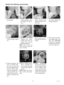
1
SLCC-6
INSTALLATION & OPERATING MANUAL
BUNN-O-MATIC CORPORATION
POST OFFICE BOX 3227
SPRINGFIELD, ILLINOIS 62708-3227
PHONE: (217) 529-6601 FAX: (217) 529-6644
To obtain the Illustrated Parts Catalog, visit the Bunn-O-Matic website, at www.bunn.com. This is absolutely FREE,
and the quickest way to obtain the catalog. Contact Bunn-O-Matic Corporation at 1-800-286-6070 to obtain a paper
copy of the required Illustrated Parts Catalog mailed via U.S. Postal Service.
39328.0000A 01/07 ©2007 Bunn-O-Matic Corporation
www.bunnomatic.com
BUNN-O-MATIC COMMERCIAL PRODUCT WARRANTY
Bunn-O-Matic Corp. (“BUNN”) warrants equipment manufactured by it as follows:
1) All equipment other than as specified below: 2 years parts and 1 year labor.
2) Electronic circuit and/or control boards: parts and labor for 3 years.
3) Compressors on refrigeration equipment: 5 years parts and 1 year labor.
4) Grinding burrs on coffee grinding equipment to grind coffee to meet original factory screen sieve analysis:
parts and labor for 3 years or 30,000 pounds of coffee, whichever comes first.
These warranty periods run from the date of installation BUNN warrants that the equipment manufactured by
it will be commercially free of defects in material and workmanship existing at the time of manufacture and
appearing within the applicable warranty period. This warranty does not apply to any equipment, component or
part that was not manufactured by BUNN or that, in BUNN’s judgment, has been affected by misuse, neglect,
alteration, improper installation or operation, improper maintenance or repair, damage or casualty. This warranty is
conditioned on the Buyer 1) giving BUNN prompt notice of any claim to be made under this warranty by telephone
at (217) 529-6601 or by writing to Post Office Box 3227, Springfield, Illinois 62708-3227; 2) if requested by
BUNN, shipping the defective equipment prepaid to an authorized BUNN service location; and 3) receiving prior
authorization from BUNN that the defective equipment is under warranty.
THE FOREGOING WARRANTY IS EXCLUSIVE AND IS IN LIEU OF ANY OTHER WARRANTY, WRITTEN OR
ORAL, EXPRESS OR IMPLIED, INCLUDING, BUT NOT LIMITED TO, ANY IMPLIED WARRANTY OF EITHER
MERCHANTABILITY OR FITNESS FOR A PARTICULAR PURPOSE. The agents, dealers or employees of BUNN
are not authorized to make modifications to this warranty or to make additional warranties that are binding on
BUNN. Accordingly, statements by such individuals, whether oral or written, do not constitute warranties and
should not be relied upon.
If BUNN determines in its sole discretion that the equipment does not conform to the warranty, BUNN, at its
exclusive option while the equipment is under warranty, shall either 1) provide at no charge replacement parts
and/or labor (during the applicable parts and labor warranty periods specified above) to repair the defective
components, provided that this repair is done by a BUNN Authorized Service Representative; or 2) shall replace
the equipment or refund the purchase price for the equipment.
THE BUYER’S REMEDY AGAINST BUNN FOR THE BREACH OF ANY OBLIGATION ARISING OUT OF THE SALE OF
THIS EQUIPMENT, WHETHER DERIVED FROM WARRANTY OR OTHERWISE, SHALL BE LIMITED, AT BUNN’S
SOLE OPTION AS SPECIFIED HEREIN, TO REPAIR, REPLACEMENT OR REFUND.
In no event shall BUNN be liable for any other damage or loss, including, but not limited to, lost profits, lost sales,
loss of use of equipment, claims of Buyer’s customers, cost of capital, cost of down time, cost of substitute
equipment, facilities or services, or any other special, incidental or consequential damages.
BUNN and SSLC-6 are either trademarks or registered trademarks of Bunn-O-Matic Corporation.
39328 012607
INTRODUCTION
This equipment dispenses hot beverages or soups on demand from powdered product. It is indoor use only on
a sturdy counter or shelf.
TABLE OF CONTENTS
Introduction.............................................................................................................................................3
User Notices............................................................................................................................................4
Initial Set-up............................................................................................................................................5
Electrical Requirements...........................................................................................................................5
Electrical Hook-up....................................................................................................................................5
Plumbing Requirements..........................................................................................................................5
Plumbing Hook-up...................................................................................................................................5
Operating Controls...................................................................................................................................6
Installing Pump Tubing............................................................................................................................8
Initial Fill & Heat.......................................................................................................................................9
Liquid Level Control.................................................................................................................................9
Rinse Alarm Feature.................................................................................................................................9
Programming The Dispenser.................................................................................................................10
Display Mode...................................................................................................................................10
Program Mode.................................................................................................................................13
Priming The Concentrate Lines..............................................................................................................16
Draining The Hot Water Tank.................................................................................................................17
Operating The Dispenser........................................................................................................................17
Carafe Dispense Mode.....................................................................................................................17
Hot Water Mode...............................................................................................................................17
Cleaning And Preventive Maintenance...................................................................................................18
Daily Rinsing....................................................................................................................................18
Daily Parts Washing.........................................................................................................................18
Weekly Sanitizing.............................................................................................................................18
Weekly Parts Washing.....................................................................................................................19
Air Filter Cleaning.............................................................................................................................19
Replacing The Pump Tubing..................................................................................................................20
Calibrating The Dispenser......................................................................................................................21
Troubleshooting Guide...........................................................................................................................23
Field Calibration of the Concentrate Pumps...........................................................................................25
Calibrating of the Concentrate Pumps..............................................................................................25
Calibration the Dispenser Flow Rate.................................................................................................26
Field Calibrating the Empty Product Warning.........................................................................................26
Field Adjustment of Powder Hoppers...............................................................................................27
Electrical Wiring Schematics..................................................................................................................28
39328 012607
USER NOTICES
The notices on this dispenser should be kept in good condition. Replace unreadable or damaged labels.
This equipment must be installed to comply with the
Basic Plumbing Code of the Building Officials and
Code Administrators International, Inc. (BOCA) and
the Food Service Sanitation Manual of the Food and
Drug Administration (FDA). For models installed
outside the U.S.A., comply with the applicable
Plumbing /SanitationCode.
00656.0000
PLACE
CUP
HERE
00986.0000
00870.0000
39474.0000
11646.0002
RINSE ALARM
If all LED’S on control panel are flashing, and LED display shows
“RINSE”, a rinse function is required to clear.
1. Place minimum 32 ounce container under dispense nozzles.
2. Place top switch in “RINSE” position.
3. Press any dispense switch on front door. Rinse will automatically
dispense for 15 seconds, then stop
4. Place top switch in “NORMAL” position.
5. Discard rinse water and close door.
Center container under dispense point.
Keep hands away.
All nozzles dispense HOT LIQUID.
To stop rinse, press STOP button on door.
ADVERTENCIA
Centre el recipiente debajo del punto de distribución.
Mantenga alejadas las manos.
Todas las toberas distribuyen LÍQUIDO CALIENTE.
Para detener el enjuague, pulse el botón STOP de
la puerta.
ALARMA DE ENJUAGUE
37881.0000
Si destellan todos los LED del panel de control y en la pantalla de LED
aparece “RINSE” (ENJUAGAR), se requiere aplicar la función de enjuague
para borrar la alarma.
1. Coloque un recipiente de 1 l (32 onzas) como mínimo debajo de las
toberas de distribución
2. Coloque el conmutador superior en la posición “RINSE”.
3. Pulse cualquier interruptor de distribución de la puerta delantera. Se
distribuye automáticamente el enjuague durante 15 segundos y luego se
detiene.
4. Coloque el conmutador superior en la posición “NORMAL”.
5. Deseche el agua de enjuague y cierre la puerta.
39591.0000
39328 012607
INITIAL SET-UP
1. Apply the four non-skid pads from the parts box to the bottom of the legs.
2. Remove the drip tray assembly and drip tray bracket from the parts box.
3. Place a set of key holes in the drip tray bracket over the lower two screws in the panel below the hopper access door; push down gently and tighten screws.
ELECTRICAL REQUIREMENTS
CAUTION - The dispenser must be disconnected from the power source until specified in Electrical Hook-Up.
The dispenser can be wired to a 120V up to 240V ac, 50 or 60Hz power source, 2 wire with ground.
Refer to the dispenser’s dataplate for exact voltage requirements.
Electrical Hook-Up
CAUTION – Improper electrical installation will damage electronic components.
1. An electrician must provide electrical service as specified.
2. Using a voltmeter, check the voltage and color coding of each conductor at the electrical source.
3. Connect the dispenser to the power source.
4. Place the main power switch in the "ON" position.
5. If plumbing is to be hooked-up later be sure the dispenser is disconnected from the power source. If plumbing has been hooked-up, the dispenser is ready for Initial Fill & Heat.
PLUMBING REQUIREMENTS
This dispenser must be connected to a cold water system with operating pressure between 20 and 100 psi (138
and 690 kPa). This water source must be capable of producing a minimum flow rate of 4.5 fl. oz. (133.1 ml) per
second. A shut-off valve should be installed in the line before the dispenser. Install a regulator in the line when
pressure is greater than 100 psi (690 kPa) to reduce it to 50 psi (345 kPa). The water inlet fitting is .25" (9.52
mm) flare.
NOTE - At least 18 inches (457 mm) of an FDA approved flexible beverage tubing, such as reinforced braided
polyethylene or silicone, before the dispenser will facilitate movement to clean the countertop. Bunn-O-Matic
does not recommend the use of a saddle valve to install the dispenser. The size and shape of the hole made in
the supply line by this type of device may restrict water flow.
This equipment must be installed to comply with the Basic Plumbing Code of the Building
Officials and Code Administrators International, Inc. (BOCA) and the Food Service Sanitation Manual of the Food and Drug Administration (FDA). For models installed outside the
U.S.A., you must comply with the applicable Plumbing/Sanitation Code for your area.
NOTE - If a backflow prevented is required by code, a shock arrestor should be installed between backflow preventer
and dispenser. Installing the shock arrestor as close to the dispenser as possible will provide the best results.
PLUMBING HOOK-UP
1. Flush the water line and securely attach it to the flare fitting on the bottom of the dispenser.
2. Turn-on the water supply.
39328 012607
OPERATING CONTROLS AND INTERFACE
1.
2.
3.
4.
5.
Carafe Button: Momentary pushed to select carafe size dispense of coffee.
Stop Button: Momentary pushed to stop dispensing.
Hot Water Button: Push and Hold to dispense hot water.
Decaf Button: Momentarily pushed to select Decaffeinated coffee.
DBL SHOT Button: Momentarily pushed to select double shot of espresso, or extra strength coffee or coffee
base specialty beverages.
6. Cup Size Buttons: Momentarily pushed to select beverage size to dispense.
7. Dispense Buttons: Momentarily pushed to dispense selected beverage.
8. Decaf refill LED: Illuminates when left (Decaf) concentrate can needs replaced.
9. Coffee (Regular) refill LED: Illuminates when right (Regular) concentrate can needs replaced.
10.Main Power Switch: Removes AC power to tank heater and control circuits.
11.Function Selector Switch: Allows the user to select different dispensing functions (Located behind the
splash guard panel)
a. Rinse: Dispenses hot water only- Flushes the powder and coffee mixing chambers and dispense lines
and tips.
b. Prime: Dispenses concentrates only – Primes concentrate pumps.
c. Normal: Normal dispense mode – Dispenses mixed product.
12.Mode Selector Switch: Allows the user to select different operating modes.
a. Run: Normal operating position.
b. Night: Anti-pilfering mode that disables dispensing, but keeps heater and chiller operational.
WARNING – The NIGHT Mode does not remove AC power from the dispenser. Disconnect power source before
servicing the dispenser.
c. Program: Enables programming and set up of the dispenser.
13.Programming Switches: Used in conjunction with the LED display to program and calibrate the dispenser to
customer specific requirements.
a. Menu: used to scroll to the next menu screen.
b. (+): used to increase the display value.
c. (-): used to decrease the display value.
14.LED Display: Displays programming menus and fault messages.
10
39328 012607
OPERATING CONTROLS (Continued)
8
4
1
5
2
6
9
3
6
7
14
11
12
13
39328 012607
INSTALLING PUMP TUBING
1. Loosen the thumbscrews securing the tubing retainer plates to the pump bodies and set the retainer plates
aside.
2. Depress the tension screws and remove them from the notch in the pump body, releasing the spring tension
on the pump bands.
3. Apply lubricant (BUNN-O-Matic part no. M2531.0001) to the middle section of the new pump tubing.
4. Insert the free end of the pump tubes over the outlet fittings in the bottom of the chiller cabinet as far as
possible.
5. Carefully wrap the new tubing around the rotors, making sure that the elbows end up parallel to the rotor
face.
6. Depress the tension screws and insert it in the notch in the pump body, reapplying spring tension on the
pump bands.
7. Replace the tubing retainer plates and tighten the thumbscrews.
8. Open the product containers and insert the stainless steel drawtubes into the containers.
Note: Replacement Tube Kits can be purchased from BUNN-O-MATIC. Order part no. 39329.1000
9. Seat pump tubes into notches on product shelf drip pan as shown.
10. Prime the pumps. Refer to Priming the Concentrate Lines section.
Thumbscrew
Tension
Screw
Remove Retaining Plate Release Spring Tension
2.0”
2.0”
Lubricate between arrows
Lubricate New Tube
Tension Screw
Tube Clamp
Install New Tubing
Completed Installation
39328 012607
INITIAL FILL & HEAT
1. Turn on the water supply and connect the dispenser to the power source.
2. Water will automatically flow into the tank to the proper level and then shut-off. This will take less than ten
minutes.
3. A tank full of cold water will take approximately fifty minutes for the water to heat at 120 volts, approximately
15 minutes at 240 volts.
4. Fill the hoppers with the dry product to be dispensed. Hot chocolate in the left hopper, powder milk product
in the right hopper.
5. The LED display on the control panel behind the door splash panel will alternately display the tank water
temperature and the cold shoe temperature.
LIQUID LEVEL CONTROL
The system automatically maintains the hot water tank’s level by energizing the refill solenoid when the water
level drops below the liquid level probe. If the system has not successfully refilled in 15 minutes, a refill error
occurs. When a refill error occurs, the refill solenoid is de-energized. Once the cause of the refill error has been
investigated and cured, the system can be reset by both disconnecting (for at least 5 seconds) and then reconnecting the power to the machine.
RINSE ALARM FEATURE
Periodic rinsing of the mix chambers and dispense tips is essential for proper maintenance and optimum performance of the dispenser. The dispenser is shipped from the factory with the rinse timer enabled.
The rinse timer automatically keeps track of the time since the dispenser was last run through a rinse sequence.
If the dispenser detects that a rinse sequence has not been run for the desired time, all LEDs’ on the membrane
switch on the front door will flash, and "RINSE" will be displayed on the LED display behind the door splash
panel.
Rinse Procedure:
1. Open the front door and place the Normal/Program/Rinse switch in the RINSE position.
2. Place a large container under the dispense nozzle. Press any dispense button on the front door. The LED
display above the programming buttons will begin counting down from 15. The rinse will terminate when
the display reaches “0”.
3. Return the Normal/Program/Rinse switch to the NORMAL position, and close the front door.
39328 012607
PROGRAMMING THE DISPENSER
Open the dispenser door to access the digital programming module with LED display.
Two basic modes are available to the operator: Display Mode and Program Mode.
To enter the Display Mode, Set the RUN/NIGHT/PROGRAM Switch to the RUN position.
To enter the Program Mode, Set the RUN/NIGHT/PROGRAM Switch to the PROGRAM position.
Display Mode: Used to view the current set-up values. Use the MENU button to scroll to the next display.
NOTE: The display blanks out after two minutes of inactivity. Press the MENU button to activate the display.
LCD DISPLAY DISPLAY MODE DESCRIPTION
190
MENU
(-)
(-)
(-)
(-)
04
MENU
05
MENU
(+)
88
(-)
Set Tank Ready Temperature
Displays target Tank Lockout Temperature (°F)
Refill Threshold
Display tank Refill Threshold
Left hopper motor Displays default power setting for Left
Hopper Motor
Right hopper motor Displays default power setting for
Right Hopper Motor
(+)
80
(-)
Displays target Tank Temperature
(°F)
(+)
03 155
MENU
Tank Temperature
(+)
02 180
MENU
Alternates between Tank Temperature
and Cold Shoe Temperature
(+)
01 190
MENU
Home View
(+)
10
39328 012607
PROGRAMMING (Continued)
LCD DISPLAY DISPLAY
MODE DESCRIPTION
Displays Left Coffee Dispense Ration
Decaf Dispense Ration
(XXX:1)
06
MENU
38
(-)
07
MENU
38
(-)
08
MENU
(+)
10
(-)
09
MENU
(+)
(+)
10
(-)
(+)
10 450
MENU
(-)
(-)
(+)
1 2 16.0
MENU
(-)
Displays Right Coffee Dispense Ration (XXX:1)
Decaf Espresso Ration
Displays Left Espresso Dispense Ration (XXX:1)
Regular Espresso Ration
Displays Right Espresso Dispense
Ration (XXX:1)
Empty Product Threshold
Displays Empty Product Threhold
(+)
1 1 11.0
MENU
Regular Dispense Ration
(+)
Small Cup Dispense Time
Large Cup Dispense Time
11
Displays Small Cup Dispense time
Displays Large Cup Dispense time
39328 012607
PROGRAMMING (Continued)
LCD DISPLAY DISPLAY MODE DESCRIPTION
13
MENU
34
(-)
14
MENU
15
MENU
16
MENU
(-)
(-)
(+)
6.0
(-)
(+)
1 9 EnA
MENU
(-)
Powder Whipper Delay Off Powder Auger Motor Delay on
Displays Powder Auger Motor Delay
On time
Rinse Required time
Displays hours for Rinse Required
Small Espresso Dispense time
(-)
Displays Small Espresso Dispense
time
Large Espresso Dispense time
Displays Large Espresso Dispense
time
"DBL SHOT" disable
Displays enable/disable selection of
"DBL SHOT"
(+)
C P 0 XX
MENU
Displays Powder Whipper Motor Delay Off time
(+)
3.0
18
MENU
(+)
24
17
MENU
(+)
0.5
(-)
Displays Decanter Dispense time
(+)
1.8
(-)
Decanter Dispense Time
(+)
Displays Software Version # - Exits to
home View After 3 sec.
12
39328 012607
PROGRAMMING (Continued)
Program Mode: Used to change or enter new set-up values.
To enter the Program Mode, Set the RUN/NIGHT/PROGRAM Switch to the PROGRAM position, the unit will
display “__PPP” to indicate it is in the Program Mode. Use the MENU switch to scroll to the next display. Use
the Increase (+) and Decrease (-) switch to adjust the values.
LCD DISPLAY PROGRAM MODE DESCRIPTION
01 190
MENU
(-)
(+)
02 180
MENU
(-)
(+)
03 155
MENU
(-)
(+)
04 r un
MENU
(-)
04
MENU
(+)
05 r un
MENU
(-)
05
MENU
(+)
80
(-)
Default = 190°F
Set Tank Ready Temperature
Default = 180°F
Refill Threshold
Set tank refill threshold
Default = 155
Left hopper motor Press any beverage dispense switch,
left hopper motor will run for 10 seconds. Refer to Field Calibration of
Powder Hoppers
(+)
88
(-)
Tank Temperature
(+)
Left hopper motor Set left hopper auger power level
Default = 88
Right hopper motor Press any beverage dispense switch,
right hopper motor will run for 10
seconds. Refer to Field Calibration of
Powder Hoppers
Right hopper motor Set right hopper auger power level
Default = 80
13
39328 012607
PROGRAMMING (Continued)
LCD DISPLAY PROGRAM MODE DESCRIPTION
06
MENU
38
(-)
07
MENU
38
(-)
08
MENU
(+)
10
(-)
09
MENU
(+)
(+)
10 450
MENU
(-)
(-)
(+)
1 2 1 6. 0
MENU
(-)
13
MENU
(+)
34
(-)
Regular Dispense Ration
Set Regular Coffee Ratio
Default = 38:1
Decaf Espresso Ration
Set Left Espresso Ration
Default = 10:1
Regular Espresso Ration
Empty Product Threshold
Set Right Espresso Ration
Default = 10:1
Set Conductance Threshold
Default = 450
(+)
1 1 1 1. 0
MENU
Set Decaf Coffee Ratio
Default = 38:1
(+)
10
(-)
Decaf Dispense Ration
Small Cup Dispense Time
Set Small Cup Dispense time Default=
11.0 seconds
Large Cup Dispense Time
Set Large Cup Dispense time Default=
16.0 seconds
Decanter Dispense Time
Set Decanter Dispense time Default=
34.0 seconds
(+)
14
39328 012607
PROGRAMMING (Continued)
LCD DISPLAY PROGRAM MODE DESCRIPTION
14
MENU
1. 8
(-)
15
MENU
0. 5
(-)
16
MENU
(-)
(+)
3. 0
(-)
(+)
6. 0
18
MENU
(+)
24
17
MENU
(+)
(-)
(-)
Set Powder Whipper Motor Delay Off
time
Default = 1.8 seconds
Powder Auger Motor Delay on
Set Powder Auger Motor Delay On
time
Default = .5 seconds
Rinse Alarm Timer
Displays hours for Rinse Alarm
Default = 24 hours
Small Espresso Dispense time
Set Small Espresso Dispense time.
Default = 3.0 seconds
Large Espresso Dispense time
Set Large Espresso Dispense time.
Default = 6.0 seconds
(+)
1 9 EnA
MENU
Powder Whipper Delay Off "DBL SHOT" disable
(+)
C P 0 XX
MENU
(-)
Displays enable/disable selection of
"DBL SHOT"
Default = Enable
Displays Software Version # - Exits to
Home View After 3 sec.
(+)
15
39328 012607
PRIMING THE CONCENTRATE LINES
1.
2.
3.
4.
5.
Open the dispenser door.
Select Prime on the Function Selector Switch and Run on the Mode Selector Switch.
Close the dispenser door.
Place a container under the dispense tip.
Activate the appropriate dispense button, (DECAF or COFFEE) until concentrate flows from the dispense
nozzle. Priming may take 10 to 20 seconds.
6. Open the dispenser door; select Normal on the Function Selector Switch.
Note: Concentrate may continue to drip out of dispense tip. The user may wish to Rinse (refer to Rinsing) the
dispenser to clean out the remaining concentrate.
2
16
6
39328 012607
DRAINING THE HOT WATER TANK
CAUTION - The dispenser must be disconnected from the power source throughout these steps
1. Disconnect the dispenser from the power source.
2. Open front door and place Main Power Switch in the OFF position and let the water in the tank cool before
draining.
3. Shut off and disconnect the incoming water supply.
4. Remove the drip tray and access panels below the door.
5. Pull the clamped end of the silicone tube out of the dispenser and direct it into a drain or a container large
enough to hold the volume of water in the tank, 4.0 gallons.
6. Make certain the shut off clamp is locked tightly on the tube, and then remove the snap type clamp and
plug from end of tube.
7. Carefully release the shut off clamp to let the water drain from the tank.
NOTE - The dispenser must be refilled using the INITIAL FILL & HEAT steps before reconnecting to the power
source.
OPERATING THE DISPENSER
Set the Function Selector Switch to NORMAL and the Mode Selector Switch to RUN
1. Simply place a cup on the drip tray beneath the center dispense nozzle.
2. Press the DECAF button if a decaffeinated beverage is desired.
3. Press the DBL SHOT button if an extra strength coffee based beverage is desired.
4. Select desired beverage size, small or large cup.
5. Press the button to dispense the desired beverage. Dispensing is portion controlled, and will automatically
stop when correct amount of beverage has been dispensed.
6. Pressing the STOP button in the center of the membrane switch will stop dispensing.
CARAFE DISPENSE MODE. Refer to Programming Functions to set up this volume
1. Place the appropriate size container beneath the dispensing tip.
2. Press the button with the decanter icon, and then press either DECAF or the COFFEE button to begin dispensing.
3. The dispensing can be stopped at any time by pressing the STOP button.
HOT WATER MODE
1. Place a container under the dispense tip.
2. Press and hold the HOT WATER button to dispense hot water.
3. Remove the container.
17
39328 012607
CLEANING & PREVENTATIVE MAINTENANCE
General Cleaning and Sanitizing Procedures Note: The BUNN¨ SLCC-6 dispenser incorporates a “user selectable” rinse reminder feature, which flashes the LED’s on the front panel when it is time to rinse.
Daily: RINSING
1. Open the front door and place the Normal/Program/Rinse switch in the RINSE position.
2. Place a ½ gal (2 liter) container under the dispense nozzle. Press any dispense button on the front door. The
LED display above the programming switches will begin counting down from “15”. The rinse will terminate
when the display reaches “0”.
3. Return the Normal/Program/Rinse switch to the NORMAL position, and close the front door.
Daily: PARTS WASHING
1. Remove and wash the drip tray and drip tray cover in a mild detergent solution. Rinse thoroughly.
2. Wipe the splash panel, dispense nozzles, door, and cabinet with a clean damp cloth.
Weekly: SANITIZING
1. Open the dispenser door and set the Function Switch to Prime and the Mode Selector Switch to Run.
2. Remove stainless steel drawtube from the product container and set the product container aside.
3. Place the stainless steel drawtube into a one-quart (1 liter) container of warm soapy tap water 140°F
(60°C).
4. Place an empty container under dispense nozzle area and depress the corresponding dispense button (COFFEE or DECAF) until the clean soapy water is dispensed from the dispense nozzle.
5. Repeat steps 3 and 4 with warm tap water 140°F (60°C) to rinse the soapy water from the pump tubing.
Continue depressing the dispense switch until the water is clear, and no soapy water is being dispensed.
6. Prepare one-quart (1 liter) of sanitizing solution with at least 100 ppm of available chlorine in 120°F (48.9°C)
water.
7. Repeat steps 3 and 4 with the sanitizing solution. Once sanitizing solution is being dispensed, release the
dispense switch and allow the solution to sit for 5 minutes.
8. After the sanitizer has set in the lines for 5 minutes, repeat step 5 with warm tap water to flush out the sanitizing solution.
9. Wipe the outside of the draw tube with a clean, damp cloth, and insert the drawtube into the product container and return it to the cabinet.
10.Repeat steps 1 through 9 for other dispense head.
11.Clean mixing/whipping chamber components, hoses and nozzles per Weekly: Parts Washing and Sanitizing procedure.
12.Rinse machine per the Daily: Rinsing procedure.
13.Select Normal on the Function Switch and Run on the Mode Selector Switch.
14.Dispense coffee, Regular or Decaf, until the concentrate and water mixture appears at the dispense nozzle.
Continue to dispense at least 12 ounce (355 ml) of concentrate/water mixture and discard.
Air Filter Cleaning
Monthly cleaning of the air filter is recommended. Severe conditions may
require more frequent cleaning.
1. From right side, reach under machine and snap filter retainer off of the
fan guard.
2. Remove filter, rinse with water, pat dry, and replace in retainer
3. Snap filter and retainer assembly back onto fan guard.
18
39328 012607
Weekly: Parts Washing and Sanitizing
1. Remove elbows from
both hoppers.
2. Remove elbows from
mixing chambers, twisting slightly to help release.
3. Rotate tab at bottom of
mixing chamber bases
counter clock wise to release base.
4. Remove mixing chamber
and steam collector by
pulling straight out.
5. Remove frother disk from
shaft by pulling straight
out.
6. Rotate tab on mixing
chamber base further
counter clock wise, and
remover from shaft by
pulling straight out.
NOTE: Insure O-ring and
shaft seal are in place during re-assembly.
7. Remove dispense hoses
from dispense nozzle assembly.
8. Clean all parts removed in
warm soapy water. Use
Bunn P/N 33685.0000
cleaning brush provided
to clean bores and orifices. Rinse in cold water.
9. Prepare one-gallon (3.8
liter) of sanitizing solution with at least 100
ppm of available chlorine
in 120°F (48.9°C) water.
Soak all cleaned parts in
sanitizing solution for 5
minutes, then rinse thoroughly in cold water, and
dry.
10.Rinse cleaning brush,
dip in sanitizing solution, and brush the bore
of each of four dispense
nozzles.
NOTE: Repeat this procedure for each nozzle separately.
11.When
reassembling
parts, be sure to align arrow on frother disk with
flat on whipper motor
shaft, and rotate tab on
whipper base clock wise
to the vertical position to
lock mixing chamber.
19
39328 012607
REPLACING THE PUMP TUBING
The pumps and tubing used in the dispenser are designed to give maximum performance and long life. However,
the tubes are a wear item and must be replaced periodically. How long the tube last is dependent on usage and
properties of the concentrate. Excessive wear will reduce the output of the pumps resulting in a weak mixed
beverage. Bunn-O-Matic recommends replacing the Pump Tubing a minimum of once every 6 months or sooner
if warranted.
Refer to the Tube Replacement Instruction inside the Cabinet door.
Note: To avoid concentrate spills, rinse the pump tubing with warm tap water prior to removing the tubes, (Refer
to steps 1 - 4 of the Weekly Sanitizing instructions).
1. Loosen the thumbscrews securing the tubing retainer plates to the pump bodies and set the retainer plates
aside.
2. Depress the tension screws and remove them from the notch in the pump body, releasing the spring tension
on the pump bands. Remove and discard pump tube assemblies.
3. Apply lubricant (BUNN-O-Matic part no. M2531.0001) to the middle section of the new pump tubing.
4. Insert the free end of the pump tubes over the outlet fittings in the bottom of the chiller cabinet as far as
possible.
5. Carefully wrap the new tubing around the rotors, making sure that the elbows end up parallel to the rotor
face.
6. Depress the tension screws and insert it in the notch in the pump body, reapplying spring tension on the
pump bands.
7. Replace the tubing retainer plates and tighten the thumbscrews.
8. Open the product containers and insert the stainless steel drawtubes into the containers.
Note: Replacement Tube Kits can be purchased from BUNN-O-MATIC. Order part no. 39329.1000
9. Seat pump tubes into notches on product shelf drip pan as shown.
10.Prime the pumps. Refer to Priming the Concentrate Lines section.
Thumbscrew
2.0”
Tension
Screw
Remove Retaining Plate
2.0”
Lubricate between arrows
Release Spring Tension
Remove Tubing
Lubricate New Tube
Tension Screw
Tube Clamp
Install New Tubing
Completed Installation
20
39328 012607
CALIBRATING THE DISPENSER
NOTE: The SLCC-6 is calibrated at the factory and does not normally need to be re-calibrated. To enter the
Calibration Mode, Set the RUN/NIGHT/PROGRAM Switch to the PROGRAM position and then hold the MENU
switch down for 10 seconds.
LCD DISPLAY CALIBRATION MODE DESCRIPTION
C1 r u n
MENU
(-)
C1
MENU
(+)
43
(-)
(-)
C2
MENU
(-)
C3
MENU
(+)
41
(-)
Enter ml collected from the 20 sec.
test above.
Default = 43
Right (Regular) Pump Cal.
Set PRIME-NORMAL-RINSE switch
to PRIME position
Press the COFFEE button, right pump
will run for 20 seconds. Refer to Field
Calibration of the Concentrate Pumps
Enter ml collected from the 20 sec.
test above.
Default = 43
(+)
C3 r u n
MENU
Right (Regular) Pump Cal.
(+)
43
(-)
Left (Decaf) Pump Cal.
Set PRIME-NORMAL-RINSE switch
to PRIME position.
Press the DECAF button, left pump
will run for 20 seconds. Refer to Field
Calibration of the Concentrate Pumps
(+)
C2 r u n
MENU
Left (Decaf) Pump Cal.
(+)
Left (Decaf) Water Rate
Set PRIME-NORMAL-RINSE switch
to RINSE position
Press the DECAF button, water will
flow for 20 seconds. Refer to Field
Calibration of the Concentrate Pumps
Left (Decaf) Water Rate
Enter Liters collected from 20 sec.
test above
Default = 41
21
39328 012607
CALIBRATING THE DISPENSER (Continued)
LCD DISPLAY CALIBRATION MODE DESCRIPTION
C4 r u n
MENU
(-)
C4
MENU
(+)
41
(-)
(+)
C5 0 3 5
MENU
(-)
(+)
C6 E 0 0
MENU
(-)
(+)
C7 - - MENU
(-)
Right (Regular) Water Rate
Set PRIME-NORMAL-RINSE switch
to RINSE position
Press the COFFEE button, water will
flow for 20 seconds. Refer to Field
Calibration of the Concentrate Pumps
Right (Regular) Water Rate
Enter Liters collected from 20 sec.
test above
Default = 41
Cooler Control Temperature
Used to set the target temperature
that Product will be held at.
Default = 35°F
Displays fault
Use the (+) or (-) button to scroll forward or backward through faults.
Reset Factory Defaults
Resets all set up values to the Factory
Default Setting.
Hold both Increase (+) and Decrease
(-) buttons for 10 seconds
(+)
C P 0 XX
MENU
(-)
Displays Software Version #Exits to home view after 3 sec.
(+)
22
39328 012607
TROUBLESHOOTING GUIDE
Error Codes
When an error has occurred, all Door LED’s will be flashing. Open the Door to access the LED Display and record the Error Code. Refer to the list of Error Codes below to identify the problem. A troubleshooting guide is
provided to suggest probable causes and remedies for the most likely problems encountered. If the problem
remains after exhausting the troubleshooting steps, contact the Bunn-O-Matic Technical Service Department.
LCD DISPLAY
EC 0 0 1
MENU
(-)
(+)
EC 0 0 2
MENU
(-)
(+)
EC 0 0 3
MENU
(-)
(+)
EC 0 0 4
MENU
(-)
(-)
(+)
EC 0 0 6
MENU
(-)
Left (Decaf) Pump Failure
Left Motor or RPM Sensor Failure.
Check Motor and RPM sensor wires
for shorts or open connections
Right (Regular) Pump Failure
Right Motor or RPM Sensor Failure.
Check Motor and RPM sensor wires
for shorts or open connections
Heating Time Too Long
Tank Heater ON Continuous For More
Than 1.5 Hour. Check heater wires
for open connections.
Fill Time Too Long
Fill Valve ON Continuous For More
Than 15 minutes. Water Turned OFF.
Refill Valve disconnected. Faulty
Valve.
(+)
EC 0 0 5
MENU
ERROR DESCRIPTION/TROUBLESHOOTING
(+)
Cool Time Too Long
Heat Sink Temp Too High
Cool Temp Sensor Above 40°F For
More Than 12 Hours. Cabinet Door
open or faulty seal. Check T.E. unit
wires for shorts or open connections.
Heat Sink Temp Higher Than 190°F.
Air Filter plugged or blocked. Ambient Temperature too high.
23
39328 012607
TROUBLESHOOTING GUIDE (Continued)
LCD DISPLAY
EC 0 0 7
MENU
(-)
(+)
EC 0 0 8
MENU
(-)
(+)
EC 0 0 9
MENU
(-)
(+)
EC 0 1 0
MENU
(-)
(+)
EC 0 1 1
MENU
(-)
ERROR DESCRIPTION/TROUBLESHOOTING
Tank Temp Sensor Failed
Sensor Reading Out Of Range (High
or Low). Faulty Sensor wiring.
Cooling Temp Sensor Failed
Sensor Reading Out Of Range (High
or Low). Faulty Sensor wiring.
Heat Sink Temp Sensor Failed
Sensor Reading Out Of Range (High
or Low). Faulty Sensor wiring.
Overflow Switch Fault
Water In Overflow Cup. Check liquid
level probe in tank lid for lime builup.
Check level probe wiring for open circuit.
Power Supply Fault
Excessive load on power supply, or
failing power supply.
(+)
24
39328 012607
Field Calibration of the Concentrate Pumps, Dispenser Flow Rates,
and Hopper Powder Throw
The factory set default values for the Pump & Dispenser Flow Rates are very accurate and typically do not need
to be field calibrated. However, if the mix ratio accuracy is ever in question, this procedure can be used to recalibrate the unit in the field. Equipment Required:
50 or 100 ml graduated cylinder, with 1 ml graduations.
1000 ml graduated container.
NOTE: You can calibrate either the Concentrate Pump, Dispenser Flow Rate and set the Hopper Throw Rate independently. Simply scroll through the menu screen to the desired section and perform only those steps. (Refer
to Calibrating the Dispenser)
Calibrating the Concentrate Pumps.
Decaf Coffee - Concentrate Pump Calibration
1. Open the door of the dispenser and select PROGRAM on the Mode Selector Switch.
2. Depress and Hold the MENU switch for approximately 10 sec. The unit will display “C1 run” when it has
entered the Calibration Mode.
3. Select PRIME on the Function Selector Switch.
4. Remove the elbow from the Left (Decaf) Coffee Mixing Chamber and place a container under the mixing
chamber outlet. Press & Hold the DECAF dispense button. The dispenser will display a 20 second count
down timer and then shut the pump OFF automatically. Release the dispense switch.
5. Stop priming and allow the tip to stop dripping. Discard the concentrate collected.
6. Place a 50 ml graduated cylinder under the Left (Decaf) Coffee Mixing Chamber outlet.
7. Press & Hold the DECAF dispense button. The dispenser will display a 20 second count down timer and then
shut the pump OFF automatically. Release the dispense switch.
8. Keep the graduated cylinder under dispense tip until all the concentrate has dripped out.
9. Measure the volume of concentrate collected in the graduated cylinder.
The acceptable range for the volume of concentrate collected is 40 - 48 ml
10.If the amount collected is not within the acceptable range, empty the graduated cylinder and repeat STEPS
6 – 9.
11.If the amount collected is still not within range, replace the pump tubing with a new Tube Kit, (refer to the
Tube Replacement Instructions).
12.When satisfied with the volume of concentrate collected, press the MENU switch. The current Calibration
volume “C1 XX” will be displayed.
13.Use the (-) / (+) keys to adjust number displayed to the amount measured in STEP 9.
Regular Coffee - Concentrate Pump Calibration
Depress the MENU button to display the Regular Concentrate Pump calibration menu “C2 run”. Repeat STEPS
3 – 13 above for the right side “Regular” pump, using the COFFEE dispense button.
(Continued)
25
39328 012607
Calibrating the Dispenser Flow Rates
Decaf Coffee - Dispenser Flow Rate Calibration
1. Select RINSE on the Function Selector Switch, and PROGAM of the Mode Selector Switch. Depress and Hold
the MENU switch for approximately 10 sec. The unit will display “C1 run” when it has entered the Calibration
Mode
2. Press the MENU button to display the Decaf Coffee Flow Rate calibration menu “C3 run”
3. Reconnect the elbow to the Left (Decaf) Coffee Mixing Chamber outlet. Place a container under Dispense Tip
and depress the DECAF dispense button. A steady stream of water comes out the tip (20 seconds).
4. Allow the tip to stop dripping. Discard the water collected
5. Place a 1000 ml graduated container under Dispense Tip.
6. Press the DECAF dispense button. The dispenser will display a 20 second count down timer and then stop
dispensing automatically.
7. Keep the graduated container under dispense tip until all the water stops dripping.
8. Measure the volume of water collected in the graduated container.
The acceptable range for the volume of water collected is .39 - .43 liters
9. If the amount of water collected is not within the acceptable range, empty the graduated container and repeat
STEPS 5 – 8.
10. If the amount collected is still not within range, inspect the dispense valves, tubing and mix chamber for
lime, kinks or other obstructions.
11. When satisfied with the volume of water collected, press the MENU switch. The current Water Calibration
volume “C3 XX” will be displayed.
12. Use the (-) / (+) keys to adjust number displayed to the amount measured in STEP 8.
Regular Coffee - Dispenser Flow Rate Calibration
Depress the MENU button to display the Regular Coffee Flow Rate calibration menu “C4 run”.
Repeat STEPS 3 – 12 above for the right side Regular dispense valve, using the COFFEE dispense button.
Field Calibrating the Empty Product Warning
The dispenser will automatically turn on the Regular or Decaf “REFILL LED”, see Operating Controls and Interface, when the corresponding container is Empty. The Refill message is triggered when the conductance sensor
reading drops below the minimum setting. The factory set minimum is 450 and should be correct for most
locations. However, in some areas the hardness of the local water supply may effect this reading. If the Refill
message doesn’t come on when the container is empty or the message comes on too early and there is still
concentrate left in the container, use the following procedure to find the correct Empty Product Threshold.
Calibrating The Empty Product Threshold
1. Remove the Coffee Concentrate Cans from the unit.
2. Open the dispenser door to access the digital programming module with LED.
3. Place a large container under the dispenser tip
4. Dispense several Large cups of Regular coffee to rinse all the concentrate out of the mix chamber and for
the Conductance reading to stabilize and stop dropping.
5. Record the nominal Conductance value displayed. (NOTE: It is typical for this value to fluctuate (+/¬25)
points about the nominal value.) This is the conductance reading of the water in your area.
6. Repeat steps 2, 3 & 4 for the Decaf Coffee dispenser.
7. Add 80 points to the larger of the Regular or Decaf conductance value. This is the new Empty Product
threshold value for your dispenser.
8. Enter this new value into the Empty Product Alarm threshold position “P8 XXX”, see Programming the Dispenser.
26
39328 012607
Field Adjustment of Powder Hoppers
The powder throw for the powder products is pre-set from the factory. It can be checked and adjusted in the
field using this calibration procedure.
Adjusting the Hopper Throw Weight
1. Open the dispenser door to access the digital programming module with LED.
2. Remove the mixing chamber below the hopper outlet elbow.
3. Select PROGRAM on the Function Selector Switch, and NORMAL for the Mode Selector Switch.
4. Press the MENU button to display the Left Hopper Motor calibration menu “04 run”
5. Hold a container under the hopper outlet elbows, and press any beverage button on the front door.
6. The left hopper will run automatically for 10 second, and then stop.
7. Weight the contents of the container. Divide by 10 to determine grams or ounce per second of throw.
8. Press the MENU button to increment the display to menu “O4 XXX”. The number displayed is the power
level drive of the hopper motor. The power level can be increased or decreased by pressing (-) or (+) button.
Each increment is equal to approximately a 1% increase or decrease in hopper motor speed.
9. Press the MENU button to display the Right Hopper Motor calibration menu “05 run”.
10.Repeat steps 5 – 8 to measure and adjust the right hopper throw weight.
11. Replace the powder-mixing chamber, and return the Function Selector Switch to the RUN position.
27
39328 012607
ELECTRICAL WIRING DIAGRAM SLCC-6
WHI
BLK
L1 N/L2
WHI
BLK
GND
BLK
LIMIT
THERMOSTAT
WHI
4
3 WHI
2
1
BLK
TANK HEATER
BLK
BLU
+ SOL -
COM
LEFT COFFEE
RIGHT COFFEE
+ SOL -
WHI
GRY
HOT WATER
1
1
BLU
+ SOL -
BRN/WHI
INLET VALVE
OVERFLOW
PROTECTION SWITCH
RED
RED
BLK
N.C.
BLK
+ SOL -
ORG
+ SOL -
N.O.
POWDER
5 J3
BLK
RED
+V
+V
-V
-V
GND
N/L2
L1
BLK
WHI
J6
GRY
WHI
5
RED
WHI
BLK
YEL
POWER SUPPLY
24VDC, 180 WATTS
8
1
LEFT
HOPPER (1)
RIGHT
HOPPER (2)
M
M
-
M
-
RIGHT
PUMP (4)
M
+
3
WHT/BLU
WHT/BLU
1
BLU
WHI/RED
WHI/RED
10
5
BLK
WHI
J5
WHI/ORG
PNK
ORG
J1
4
GRN
WHT/BLK
8
t°
RED
VIO
- M +
10
GRN
GRN
POWDER WHIPPER (1)
1
BLK
4
WHI/RED
RED/BLK
1
5
YEL
6
WHT/BLU
WHT/BLK
RED
1
ORG
2
7
3
BRN/BLK
BRN/WHI
-
+
GRN
GRY
4
1
GRN
3
-
BRN/WHI
WHT/BLU
WHT/BLK
TAN
1
RIGHT PUMP
RPM SENSOR
J15
WHI/RED
GRN
+
LEFT PUMP
RPM SENSOR
LEFT
PUMP (3)
BRN/WHI
GRN
+
RED
ORG
TANK
15
GRN
GRN
BRN/WHI
RED/BLK
LEFT COFFEE WHIPPER (3)
- M +
RIGHT COFFEE WHIPPER (4)
- M +
YEL
1
BLK
BLK
120V
RED
RED
240V
3
WHI
WHT
J11
20
GRN
M
DUAL VOLTAGE BLOWER FAN
BLU
1
MEMBRANE SWITCH
SWITCH TAIL
MEMBRANE SWITCH
1
2
3
4
5
6
7
8
9
10
1
2
3
4
5
LED TAIL 6
7
8
9
10
MENU
(-)
(+)
J14
5
BLK/WHI
ORG
MAIN CONTROL BOARD
GRN
1
RED
- M +
BLK
HEAT SINK FAN
WHI/RED
BLU
5
YEL
HEAT SINK
1 THERMISTOR
J13
WHI/BLK
10
t°
COLD SHOE
THERMISTOR
WHI/BLU
WHI/YEL
t°
4
12
THERMOELECTRICS
1
GRN
BLU
WHI
BLK
5
RED/WHI
1
GRN/WHI
BLU/WHI
RED/BLK
10
5
RED/GRN
LEFT
CONDUCTANCE
RIGHT
CONDUCTANCE
RINSE
15
VIO
10
GRY
WHI/BLK
WHI/GRY
ORG/RED
WHI/RED
PRIME
NORMAL
RED
BLU/RED
RED
WHI/VIO
J16
BLU/BLK
WHI/BLK
BLK/RED
VIO
BLK
ORG/BLK
GRN/BLK
RED
VIO
J2
20
14
28
PROGRAM
NIGHT
RUN
120-240 VOLTS AC
2 WIRE + GND
SINGLE PHASE
50/60 HZ
39328 012607
ELECTRICAL WIRING DIAGRAM SLCC-6
WHI
BLK
L1 N/L2
WHI
BLK
GND
BLK
LIMIT
THERMOSTAT
3 WHI
4
WHI
BLK
TANK HEATER
BLK
1
N.C.
BLK
2
BLU
+ SOL -
+ SOL -
COM
LEFT COFFEE
RIGHT COFFEE
+ SOL -
WHI
GRY
HOT WATER
1
1
BLU
+ SOL -
BRN/WHI
INLET VALVE
OVERFLOW
PROTECTION SWITCH
RED
RED
BLK
ORG
+ SOL -
N.O.
POWDER
RED
+V
+V
-V
-V
GND
N/L2
L1
BLK
WHI
J6
5 J3
BLK
GRY
WHI
5
RED
WHI
BLK
YEL
POWER SUPPLY
24VDC, 180 WATTS
8
1
LEFT
HOPPER (1)
RIGHT
HOPPER (2)
M
M
-
M
-
RIGHT
PUMP (4)
M
3
GRY
4
1
3
WHT/BLU
WHT/BLU
1
BLU
WHI/RED
WHI/RED
10
5
WHI/ORG
PNK
ORG
J1
4
GRN
t°
RED
VIO
ORG
GRN
120 VOLT MODELS
GRN
RED/BLK
- M +
YEL
TANK
15
BRN/WHI
LEFT COFFEE WHIPPER (3)
BLK
WHI
WHT/BLK
8
- M +
10
J5
GRN
GRN
POWDER WHIPPER (1)
1
BLK
4
WHI/RED
RED/BLK
1
5
YEL
6
WHT/BLU
WHT/BLK
RED
1
ORG
2
7
3
BRN/BLK
BRN/WHI
+
+
GRN
WHT/BLU
WHT/BLK
TAN
1
-
BRN/WHI
GRN
-
RIGHT PUMP
RPM SENSOR
J15
WHI/RED
GRN
+
LEFT PUMP
RPM SENSOR
LEFT
PUMP (3)
BRN/WHI
GRN
+
RED
1
BLK
3
WHI
J11
20
208-240 VOLT MODELS
BLK
M
RED
M
RED
WHT
WHT
GRN
BLOWER FAN
RIGHT COFFEE WHIPPER (4)
- M +
BLOWER FAN
BLU
1
MEMBRANE SWITCH
SWITCH TAIL
MEMBRANE SWITCH
1
2
3
4
5
6
7
8
9
10
1
2
3
4
5
LED TAIL 6
7
8
9
10
MENU
(-)
(+)
J14
5
BLK/WHI
ORG
MAIN CONTROL BOARD
GRN
1
RED
- M +
BLK
HEAT SINK FAN
WHI/RED
BLU
5
YEL
HEAT SINK
1 THERMISTOR
J13
WHI/BLK
10
t°
COLD SHOE
THERMISTOR
WHI/BLU
WHI/YEL
t°
4
12
THERMOELECTRICS
1
GRN
BLU
WHI
BLK
5
RED/WHI
1
GRN/WHI
BLU/WHI
RED/BLK
10
5
RED/GRN
LEFT
CONDUCTANCE
RIGHT
CONDUCTANCE
RINSE
15
VIO
10
GRY
WHI/BLK
WHI/GRY
ORG/RED
RED
PRIME
NORMAL
RED
BLU/RED
WHI/RED
WHI/VIO
J16
BLU/BLK
WHI/BLK
BLK/RED
VIO
BLK
ORG/BLK
GRN/BLK
RED
VIO
J2
20
14
29
PROGRAM
NIGHT
RUN
120 VOLTS AC OR
208-240 VOLTS AC
2 WIRE + GND
SINGLE PHASE
50/60 HZ
39328 012607