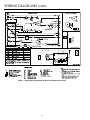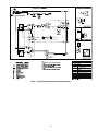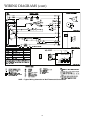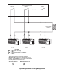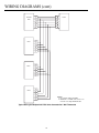
1
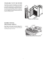
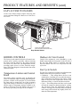
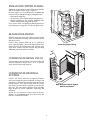
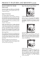
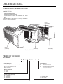
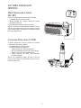
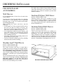
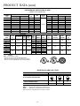
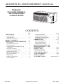
ARCHITECTS AND ENGINEERS’ MANUAL MODEL 52C PACKAGED TERMINAL AIR CONDITIONERS AND HEAT PUMPS CONTENTS Page Page APPLICATIONS . . . . . . . . . . . . . . . . . . . . . . . . . . . . 2,3 Condensate Drain Valve. . . . . . . . . . . . . . . . . . . . . . . . . 9 Condensate Removal System. . . . . . . . . . . . . . . . . . . . . 9 Heat Pumps Pay Their Own Way. . . . . . . . . . . . . . . . . 10 Heat Pump Energy Savings . . . . . . . . . . . . . . . . . . . . . 11 ORDERING DATA . . . . . . . . . . . . . . . . . . . . . . . . 12-21 Product Catalog Number . . . . . . . . . . . . . . . . . . . . . . . 12 Factory-Installed Options. . . . . . . . . . . . . . . . . . . . . . . 13 Field-Installed Accessories . . . . . . . . . . . . . . . . . . . . . 14 New Construction. . . . . . . . . . . . . . . . . . . . . . . . . . . . . . 2 Carrier Warranty . . . . . . . . . . . . . . . . . . . . . . . . . . . . . . . 2 Application Considerations . . . . . . . . . . . . . . . . . . . . . . 3 PRODUCT OVERVIEW . . . . . . . . . . . . . . . . . . . . . . . 4 PRODUCT FEATURES AND BENEFITS . . . . 5-11 Quiet Operation . . . . . . . . . . . . . . . . . . . . . . . . . . . . . . . 5 Most Efficient Performance . . . . . . . . . . . . . . . . . . . . . . 5 Efficient Fan Motor . . . . . . . . . . . . . . . . . . . . . . . . . . . . 5 No-Rust Weather Last™ Wall Sleeve and Front Panel . . . . . . . . . . . . . . . . . . . . . . . . . . . . . . . . . 6 Removable Front Panel . . . . . . . . . . . . . . . . . . . . . . . . . 6 Two-Piece Lifetime Indoor Filter . . . . . . . . . . . . . . . . . . 6 Washable Vent Air Filter . . . . . . . . . . . . . . . . . . . . . . . . 7 Bi-Directional Discharge Grille . . . . . . . . . . . . . . . . . . . 7 Easy Access to Chassis. . . . . . . . . . . . . . . . . . . . . . . . . . 8 Hidden Controls . . . . . . . . . . . . . . . . . . . . . . . . . . . . . . . 8 Enhanced Copper Tubing . . . . . . . . . . . . . . . . . . . . . . . . 9 Seamless Basepan. . . . . . . . . . . . . . . . . . . . . . . . . . . . . . 9 October 2001 DIMENSION DRAWINGS AND INSTALLATION DATA — NEW CONSTRUCTION. . . . . . . . . . . . . . . . . . . . . . . . . 22-25 PRODUCT DATA . . . . . . . . . . . . . . . . . . . . . . . . . 26-30 WIRING DIAGRAMS . . . . . . . . . . . . . . . . . . . . . 31-36 GUIDE SPECIFICATIONS . . . . . . . . . . . . . . . . .37,38 TYPICAL WARRANTY . . . . . . . . . . . . . . . . . . . .39,40 LITERATURE LIST. . . . . . . . . . . . . . . . . . . . . . . . . . 41 STANDARD COLORS . . . . . . . . . . . Inside Back Cover Copyright Carrier Corporation Cat. No. 592-075 APPLICATIONS Whether you are designing a new structure or replacing packaged terminal air conditioning units in an existing building, Carrier will meet your needs. • Hotels and motels • Nursing homes and assisted living care centers • Offices • Apartments • Single-family dwellings • Home conversions and residential add-ons • Weather-protected wall sleeve that goes in place during construction; chassis that slides in place after construction • No seasonal changeover required for cooling or heating — units are self-contained comfort systems Lower Operating Costs And Reliable Comfort For The Occupant • Heat pump models offer substantial savings over models with conventional electric resistance heaters • Individual units allow tenants to choose the degree of comfort and operating economy • Rapid servicing reduces downtime: complete chassis can be replaced in minutes without disrupting other occupants. • Each unit operates independently of other units in the building. No dependency by building on central HVAC system. Retrofit/Replacement If you are replacing existing units, your options include: • Replacing the existing wall sleeve with a Carrier Weather Last™ sleeve • Using an existing sleeve made by another manufacturer. The 52C Series chassis will fit existing GE, Amana, and Trane wall sleeves. All other sleeve applications need prior approval from Carrier. NEW CONSTRUCTION The Carrier 52C Packaged Terminal Air Conditioning (PTAC) unit is designed to meet the needs of the architect, engineer, and contractor. For unit installation, Carrier’s expert support network will assist in all applicable aspects of the construction project, from preparing a budget to start-up. ADVANTAGES FOR NEW CONSTRUCTION Design Flexibility For The Architect/Engineer • Super-quiet performance, indoors and out • No bulky duct system • No separate equipment room • No water towers or additional cooling equipment • No complex match-up of different HVAC components • Less sensitivity to building orientation (sun, wind, shade) • Optional architectural grille to permit custom exterior appearance Initial Cost Savings For The Building Owner • No expensive component HVAC system purchase • No equipment room or maintenance engineering staff • Two-part delivery to minimize on-site damage CARRIER WARRANTY Carrier’s five-year warranty is the most comprehensive in the industry. Carrier provides: • Full coverage for parts and labor for first year. • Four additional years of full coverage on sealed refrigeration systems. • Limited second through fifth year coverage on nonrefrigeration system parts. 2 APPLICATION CONSIDERATIONS Oversizing If a PTAC unit is oversized (cooling capacity is greater than required capacity for the specific application), the unit will cool the space down to the desired temperature too quickly. The unit will cycle on and off, however, dehumidification only takes place when the unit is operating. The result of this type of application in a hot and/or humid climate would be a cool, yet excessively humid, space. Installation instructions are shipped with all PTAC units. It is important that air conditioning systems be properly sized and installed for each application in order to achieve the desired temperature and humidity levels within the space to be conditioned. It is strongly recommended that a professional engineer match the PTAC units with the building structure and climate. The following application considerations are all important in choosing the proper PTAC system for the building structure. Air Infiltration Excessive air infiltration can intensify problems associated with undersizing or oversizing a PTAC unit. This can be the cause of insufficient cooling, dehumidification, or heating. Sources of air infiltration include vents, gaps around windows and doors, and improperly sealed floors, ceilings or wall joints. Undersizing If a PTAC unit is undersized (cooling capacity is less than required capacity for an application), the unit will not be able to cool the space down to the desired temperature during very hot days. The result could be warm and humid or warm and dry conditioned space. 3 PRODUCT OVERVIEW This section summarizes product features covered in detail in later sections of this manual: 2 AIR FILTERS LOUVERED FRONT PANEL 2-WAY DISCHARGE GRILLE WIRE SCREEN FRESH AIR CONTROL ARM CONTROL DOOR THERMOSTAT WITH TEMPERATURE LIMITER INDOOR COIL MODE SELECTION SWITCH ACCESS TO ELECTRICAL COMPONENTS THROUGH CONTROL BOX DOOR COPPER TUBE ALUMINUM FIN COILS BASEPAN FOR CONDENSATE REMOVAL ROTARY COMPRESSORS WALL SLEEVE Polymer, Metal or Extended Wall Sleeve — Designed for rugged duty, acoustic absorption, and attractive appearance for years to come. Rotary Compressors — Provide quiet, reliable operation. Copper Tube Aluminum Fin Coils — Enhanced coils provide durability, high performance, and ease of operation. Fresh Air Control Arm — Allows outdoor air into room through vent filter for improved air quality. Fan Cycle Switch — Dual options: (1) Continuous fan operation. (2) Cycle fan ON and OFF with compressor operation. Thermostat with Temperature Limiter — Provides improved temperature control with a temperature limiter that allows temperature range restraints for the unit by making a simple adjustment. Control Door — Provides protection for controls and enhances appearance. Easy Access to Electrical Components — Simply remove two screws and drop down the control box door. Improved Condensate Removal — Minimizes condensate water on outside of building. New Two-Piece Filter Design — Provides improved air filtration and can be removed easily for cleaning. Durable Discharge Grille — Made of polycarbonate; holds up under the toughest conditions. Louvered Front Panel — Made of high impact polystyrene. Provides improved performance and quiet operation. Mode Selection Switch — Rotary switch allows for easy selection of operating mode. 4 PRODUCT FEATURES AND BENEFITS The 52C model is a single-package, through-the-wall unit for heating and cooling hotel rooms, offices, apartments, condominiums, and residential additions. The 52C Series features include: • Improved sound quality for quiet operation • Exceeds ARI efficiency requirements with exceptional energy efficiency ratios (EERs) • Easy access, lifetime filters • User friendly controls • Easy to read dials • Enhanced temperature and humidity control • Improved condensate removal system • Multi-room structure design • Fixed wall sleeve, slide-out chassis • Attractive, durable cabinet featuring new design • Chassis that easily retrofits to most major competitors’ sleeves without use of retrofit kit • Low operating costs • No bulky duct system • No seasonal changeover The new aerodynamic split condenser shroud design improves airflow and reduces outdoor noise, providing a more relaxing outdoor environment. The new split design allows for easy access to the outdoor coil to facilitate routine cleaning of the coil. The propeller-type fan design allows for efficient low-speed operation. MOST EFFICIENT PERFORMANCE High EERs provide excellent operating economy. The system operates without bulky ductwork, separate equipment room, and complex match-up of different components. Heating and Cooling modes are available without seasonal changeover. EFFICIENT FAN MOTOR An efficient, totally enclosed PSC (permanent split capacitor) fan motor provides a choice of high or low speeds for heating and cooling. A fan-only setting provides air circulation. The fan motor requires no maintenance and no lubrication. QUIET OPERATION Occupants and neighbors are protected against noise intrusion. Indoor sound reduction is achieved because of the unit’s design and its louvered front cover, indoor scroll and blower, and heavy gage unit partition. Rotary compressors provide quiet, reliable operation. The indoor scroll provides a more uniform air discharge. 5 PRODUCT FEATURES AND BENEFITS (cont) NO-RUST WEATHER LAST™ WALL SLEEVE AND FRONT PANEL The indoor front panel and non-insulated wall sleeve use nonmetallic compounds that never rust or corrode, do not support combustion, and do not give off toxic fumes. The weather-resistant feature exceeds requirements of Underwriters’ Laboratories and resists damage caused by impact and scratching. The Weather Last feature also insulates and has up to 10 times the acoustic absorption of metal cabinets. Insulated polymer wall sleeves combine all of the above features with the addition of factory-installed insulation. The insulation helps to reduce heat loss, save energy and provides better sound absorption. Carrier’s metal wall sleeves are available in a variety of sizes for most standard and deep wall applications. All metal wall sleeves come with factory-installed closed cell insulation, designed to minimize heat loss and reduce outdoor noise transmissions into the room. Wall Sleeve REMOVABLE FRONT PANEL The louvered front panel fits firmly onto the chassis and features easy removal for service. It provides front air intake to enhance performance and quiet operation. It also allows the option of flush mounting PTAC unit to the floor. If desired, the front panel can be secured to the unit with field-supplied screws. TWO-PIECE LIFETIME INDOOR FILTER New two-piece removable filters easily slide in and out from the front of the PTAC unit and are interchangeable. The front panel does not need to be removed to access or change the filters. Removable Front Panel Two-Piece Indoor Filter 6 WASHABLE VENT AIR FILTER The unique vent system is activated by a two-position control. Fresh outside air is redirected by the vent door to an inside low-pressure area. A molded plastic filter prevents dirt and debris from entering the room side of the unit. The vent mechanism is made from noncorrosive material ensuring reliable operation. A magnet on the door and high-pressure airflow create a tight, draftfree seal when the vent door is closed. The vent will provide 50 CFM of fresh air. Outdoor Vent Filter Location BI-DIRECTIONAL DISCHARGE GRILLE The discharge grille is constructed of durable polycarbonate and is reversible. Air flows upward at a 40 degree angle to the floor but can easily be adjusted to an 80 degree angle to the floor. 40 DEGREE AIR FLOW 80 DEGREE AIR FLOW Reversible Polycarbonate Discharge Grille 7 PRODUCT FEATURES AND BENEFITS (cont) EASY ACCESS TO CHASSIS Access to the chassis simply requires removing four screws and then sliding the chassis out of the sleeve for service. CHASSIS ATTACHMENT SCREWS (SAME LOCATION ON OPPOSITE SIDE) Easy Service Access HIDDEN CONTROLS Outdoor Air Vent Control The factory-wired control box houses all control components and is quickly accessible without removing the chassis from the wall sleeve. By simply removing two screws on control box, the hinged door lowers, providing quick access to all the electrical components. The wiring diagram is located on the front of the control box door. Control of the outdoor-air vent is handled by a vent handle located under the front panel on the left side of the unit. This handle rotates to manually open and close the outdoor vent. The vent will provide 50 CFM of fresh air. Temperature Limiter and Control Knob The fan cycle switch (not available on wall thermostat models) allows the fan to operate in 2 modes: • Continuous — This setting allows the fan to run continuously, circulating air even when the temperature setting has been satisfied. This setting, which helps to keep the room temperature closer to the thermostat setting, is used for maximum comfort. • Cycle — This setting allows the fan to cycle on and off with the compressor during heating or cooling. The fan stops when the temperature setting is reached. The longer unit off-time makes this option more energy-efficient with only slightly wider variations in room temperature. Fan Cycle Switch The limiter reduces operating costs by allowing the owner to control the range of cooling and heating temperatures available to the occupant. It is located under the front panel on control box, out of the occupant’s sight. Each setting on the limiter is equivalent to 5° F and the range of temperature settings available to the owner is from 60 to 90 F. The limiter is not pre-set at the factory (providing full range for the occupant). 8 ENHANCED COPPER TUBING Enhanced copper tubing is more efficient and durable and can be repaired in the field, if required. Because copper is a very stable metal, it is durable and resists corrosion. Enhanced copper tubing increases: • heat transfer capability • the efficiency of the cooling and heating processes • thermal conductivity (by creating additional tube surface and turbulent refrigerant gas flow) Every Carrier PTAC coil undergoes thorough leak testing and pressure testing up to 350 lbs per square inch. SEAMLESS BASEPAN Seamless drawn basepan walls add protection against water accumulation resulting from storm-driven rain with heavy wind. Carrier’s deep basepan holds up to 11/2 gallons of water without spilling. Closed cell foam insulators are located between the basepan and coils, keeping coils from direct contact with the basepan and providing additional protection against corrosion. Enhanced Copper Tubing CONDENSATE DRAIN VALVE The temperature-activated drain valve opens when the outdoor temperature drops below 45 F to prevent water from freezing in the basepan. CONDENSATE REMOVAL SYSTEM Carrier’s 52C Series units have an improved condensate (water) disposal system. In addition to slinger ring technology, Carrier has developed and patented a Condensate Orifice. The orifice, along with the slinger ring, draws in water which is sprayed up onto the outdoor coil. The water then evaporates, thus providing better disposal of excess condensate, improving unit efficiency. NOTE: If it is necessary to remove 100% of the condensate, we recommend using the Carrier Drain Kit (Part No.: DRAIN-KIT-4PK). Deep Basepan Protects Against Water Accumulation 9 PRODUCT FEATURES AND BENEFITS (cont) HEAT PUMPS PAY THEIR OWN WAY How The Heat Pump Works Heat pump models are available at a nominal additional cost. In many locales, the payback is realized in just a few months. Cost and payback details are provided on the next page. Special Features Two-Stage Indoor Thermostat: In Hot Weather: The indoor thermostat senses the indoor temperature and automatically turns on the electric heat to warm the room quickly. After the desired temperature conditions have been satisfied, the thermostat automatically switches to heat pump mode. If compressor failure occurs, the thermostat will provide backup electric heat automatically. Carrier’s 52C series units provide indoor comfort in the same manner as conventional air conditioners, removing heat and humidity from indoor air. The heat and humidity is released to the outdoors. Carrier’s high efficiency design saves energy and reduces cooling costs. Outdoor Thermostat: During the heating cycle, the outdoor thermostat senses outdoor coil temperature. It switches the unit to electric heat mode when the outdoor coil temperature is 20 F or below (approximately 35 F outdoor air temperature). The thermostat switches the unit back to heat pump mode when the outdoor coil temperature rises above 35 F (approximately 45 F outdoor air temperature), which is enough to provide heat to meet demand. The entire operation is completely automatic. Reversing Valve: In Cool Weather: The reversing valve provides quiet refrigerant flow after the unit shuts off. The valve controls the direction of refrigerant flow for both heating and cooling functions and remains energized as long as the controls are in the heat position. When the cooling controls are activated, the valve automatically reverses to the cooling position. When the outdoor coil temperature is above 20 F (approximately 35 F outdoor air temperature), the heat pump draws heat from outdoor air and uses it to heat indoor air. Since heat is transferred and not produced, Carrier’s heat pump uses less electricity and reduces energy costs significantly. Manual Compressor Override Switch: This switch completely locks out the compressor. Note that the compressor and heater do not operate at the same time, thus conserving energy. In Sub-Freezing Weather: When the outdoor coil temperature falls below 20 F (approximately 35 F outdoor air temperature), the unit automatically switches on a built-in electric heater. The compressor stops and a blower circulates warm air produced by the heater. When the outdoor coil temperature rises above 35 F (approximately 45 F outdoor air temperature), heat pump operation resumes automatically. 10 HEAT PUMP ENERGY SAVINGS Heat pumps save more on operating costs during the heating cycle than heat/cool models. The table below shows that the higher initial cost of purchasing a heat pump is quickly made up in lower operating costs. Use the map to identify the climate zone’s designated number. Reading down the left-hand column of the table, select the cost/kWh rate in this zone that most closely approximates your local rate. The approximated savings and payback period is found at the intersection of your zone/rate line and the desired Btuh Cooling Capacity column. Exact savings are determined by lifestyle, local electrical rates, and climatic conditions. ZONE VI V ZONE V ZONE IV ZONE III II ZONE II ZONE I CARRIER HEAT PUMP INITIAL COST VERSUS SAVINGS OVER HEAT/COOL MODELS 7000 BTUH1 COOLING ZONE ELECTRIC CAPACITY COST/kWH Annual Savings* $.06 $ 31.00 I $.08 $ 41.69 $.10 $ 52.38 $.06 $ 47.03 II $.08 $ 63.07 $.10 $ 79.10 $.06 $112.24 III $.08 $148.59 $.10 $186.00 $.06 $ 42.76 $.08 $ 69.48 $.10 $ 87.66 IV $.12 $103.69 $.14 $121.86 $.16 $140.03 $.06 $ 41.69 $.08 $ 55.59 $.10 $ 69.48 V $.12 $ 83.38 $.14 $ 97.28 $.06 $110.10 $.08 $146.45 VI $.10 $182.79 $.12 $220.21 $60 PREMIUM Payback in Months 23 17 14 15 11 9 6 5 4 17 10 8 7 6 5 17 13 10 9 7 7 5 4 3 9000 BTUH2 COOLING CAPACITY Annual Savings* $ 58.07 $ 76.74 $ 96.44 $ 87.11 $116.15 $145.19 $108.89 $144.15 $168.00 $100.59 $132.74 $166.96 $200.15 $233.33 $266.52 $ 78.81 $105.78 $131.70 $158.67 $189.59 $206.37 $275.85 $344.30 $413.78 $75 PREMIUM Payback in Months 16 12 9 10 8 9 8 6 5 9 7 5 4 4 3 11 9 7 6 5 4 3 3 2 LEGEND kWH — Kilowatt Hour *Computer projections based on full cooling load at 95° F. Savings projected for 230 v ratings. 1Heating load is 5,000 Btuh at winter design point temperature. 2Heating load is 10,000 Btuh at winter design point temperature. 3Heating load is 15,000 Btuh at winter design point temperature. 11 12000 BTUH2 COOLING CAPACITY Annual Savings* $ 63.39 $ 82.52 $102.86 $ 94.48 $126.78 $157.87 $114.82 $153.09 $191.36 $105.25 $138.74 $174.62 $209.30 $243.98 $278.67 $ 82.52 $110.03 $137.54 $165.05 $192.56 $221.26 $295.41 $368.37 $442.52 $90 PREMIUM Payback in Months 17 13 11 11 9 7 9 7 6 10 8 6 5 4 4 13 10 8 7 6 5 4 3 2 15000 BTUH3 COOLING CAPACITY Annual Savings* $ 77.45 $103.64 $129.82 $113.45 $150.55 $187.64 $138.55 $185.45 $231.27 $127.64 $170.18 $211.64 $255.27 $297.82 $339.27 $ 99.27 $133.09 $166.91 $199.64 $233.45 $268.36 $357.82 $447.27 $536.73 $110 PREMIUM Payback in Months 17 13 10 12 9 7 10 7 6 10 8 6 5 4 4 13 10 8 7 6 5 4 3 2 ORDERING DATA For immediate assistance, call 1-800-827-7435 or contact your local Carrier dealer. Standard 52C Unit • Chassis with front panel • Electro-mechanical controls • Cord-connected chassis for 230/208V and 265V units Lead-time: Many models are in stock for immediate delivery; call for lead-times. EXTERIOR GRILLE (ACCESSORY) FRONT PANEL (STANDARD) CHASSIS (STANDARD) WALL SLEEVE (ACCESSORY) Standard 52C Unit PRODUCT CATALOG NUMBER 52 CE – 3 12 – – – 3 –– CP Chassis Options “Blank”– Standard CP – Corrosion Protection RC – Wall Thermostat Control RP – Wall Thermostat Control with Corrosion Protection Series Designation PTAC (Packaged Terminal Air Conditioner) CE – Cooling with Electric Heat CQ – Heat Pump Electric Heater Size 2 – 2.3 kW 3 – 3.4 kW 5 – 5.0 kW Cooling Capacity (nominal) 07 – 7,000 Btuh 09 – 9,000 Btuh 12 – 12,000 Btuh 15 – 15,000 Btuh Electrical Data 3 – 230/208-v, 60 Hz 4 – 265-v, 60 Hz 12 FACTORY-INSTALLED OPTIONS Wall Thermostat Control (RC,RP) Carrier’s wall thermostat control option includes: • a standard chassis with front panel • factory-installed low voltage controls for remote thermostat operation A wall thermostat must be ordered separately. NOTE: A heat/cool or heat pump thermostat is available for each application. Be sure to connect reversing valve wiring to the O connection of the thermostat for heat pump applications. comfort WALL THERMOSTAT COMFORT Corrosion Protection (CP,RP) To protect against the corrosive effects of a seacoast environment, this option includes: • a standard chassis with front panel • special protections consisting of: — painted control box and unit partitions — pre-coated aluminum coils with copper tubing — stainless steel tube sheets (outdoor coil) — totally enclosed fan motor with moistureresistant windings NOTE: All installations within one mile of the sea coast or other corrosive environment must use Corrosion Protection (CP). 13 ORDERING DATA (cont) FIELD-INSTALLED ACCESSORIES The alpine mist (a shade of beige) finish matches the front panel and blends in well with inside or outside decor. The sleeve surface is textured to prevent shine and hide scratches. Wall Sleeves Insulated Polymer Wall Sleeve It is recommended that a Carrier sleeve be used with a Carrier chassis. Locating holes in the side panels allow easy fastening of the sleeve to wall openings. Refer to dimension drawings (pages 22 and 23) for typical wall installation and unit dimensions. When installing any Carrier wall sleeve, note the following: • If more than 4 in. of sleeve projects into the room or the wall is less than 2 in. thick, an accessory subbase must be used for support. Refer to the descriptions of the Accessory Subbases on page 18. • For all applications with an accessory subbase, wall sleeve must extend 31/4 in. minimum into room and must be 31/4 in. minimum to 51/2 in. maximum above floor (including carpeting). • All Carrier’s sleeves are self pitching and must be mounted level in all directions. • The sleeve should be caulked on all sides, including both inside and outside the building. Part No.: SLEEVE-INSUL-1PK Insulated polymer wall sleeves combine all of the above features with the addition of factory-installed insulation. The insulation helps to reduce heat loss, save energy and provides better sound absorption over the non-insulated sleeve. Insulated Metal Wall Sleeves Part No.: SLEEVE-STEEL-1PK Part No.: SLEEVE-EXT24-1PK Carrier’s new metal wall sleeves are available in a variety of sizes for most applications and difficult installations. All metal wall sleeves come with factory-installed closed cell insulation, designed to minimize heat loss and reduce outdoor noise transmissions into the room. In addition, the metal wall sleeve provides a flammability rating higher than UL94-5V. Weather Last™ Wall Sleeve Part No.: WALL-SLEEVE-1PK Part No.: WALL-SLEEVE-9PK The Carrier accessory wall sleeve is made from a molded polymer that is designed for strength and durability. This material has excellent corrosion resistance and a flammability rating of UL94-5V. The polymer sleeve absorbs sound, provides better insulation than a metal sleeve, and offers years of protection against the elements. The rib configuration on the sleeve bottom allows easy chassis removal and aids in drainage. The sleeves are built with a pitch of 1/4 in. per foot. Wall sleeves must be installed level. Overflow slots are in place to divert excess water during severe weather. Corrosion-Protected Polymer Sleeve 14 OUTDOOR GRILLES Carrier recommends only the use of Carrier-supplied grilles for use on the 52C series units. However, the architectural designs of a building may dictate the use of special or oversized grilles and/or louvers. Special louvers or any special architectural treatment of the building façade that may restrict free circulation of condenser airflow should be referred to Carrier Corporation for evaluation and approval. Aluminum Architectural Outdoor Grilles (Louvered) Part No.: GRILLE-ALU-CLEAR (anodized aluminum) Part No.: GRILLE-ALU-WHITE Part No.: GRILLE-ALU-BEIGE Part No.: GRILLE-ALU-ALPIN (color matches Carrier wall sleeve) Part No.: GRILLE-ALU-BRONZ Part No.: GRILLE-ALU-MBRNZ Part No.: GRILLE-ALU-BROWN Part No.: GRILLE-ALU-LGREY Part No.: GRILLE-ALU-SGREY Part No.: GRILLE-ALU-PEACH Part No.: GRILLE-ALU-MELON Part No.: GRILLE-ALU-RDBRK Part No.: GRILLE-ALU-BLUE Part No.: GRILLE-ALU-GREEN This premium line of decorative outdoor grilles will enhance the appearance of any building. The grilles are made of strong, durable, extruded, anodized aluminum and are designed to be mounted easily from inside the room. These elegant grilles have baked enamel finishes available in several colors. See inside of back cover for standard colors and color samples. For more information on custom colors and sizes, contact Reliable Products at 1-800-239-4621. Architectural Grille in Aluminum or Polymeric Polymeric Architectural Outdoor Grilles (Louvered) Part No.: GRILLE-PLA-BROWN Part No.: GRILLE-PLA-BEIGE This value line of polymeric outdoor grilles will blend attractively with most building exteriors. Mounted easily from inside the room, the one-piece, molded grille is designed for protection, enhanced appearance, and superior weather-resistance. The grille is made of durable polymer and has a colorfast, lightly-textured finish that blends well with most exterior finishes. Standard Outdoor Aluminum Grille Part No.: GRILLE-ALU-STAMP This cost-effective, one-piece standard grille is made from durable anodized aluminum. The grille is lightweight, has a clear finish, and is easy to install from inside the room. Standard Grille 15 ORDERING DATA (cont) Outdoor Grille Selection IMPORTANT: If you wish to use a grille not made by Carrier for your Carrier unit(s), contact the Carrier Application Engineering Group at 1-800-894-6449. The following guidelines must be followed in the initial selection of any alternate exterior grille or louver: 1. The louver must have a minimum of 65% free area. Free area is the minimum area of the opening in an air inlet or outlet in which air can pass. Free Area (%) = X/Y. 2. The louver should be attached to the wall sleeve in a manner that will prevent recirculation of condenser discharge air into the inlet. In most applications, baffles, splitters, and/or gasket will be required between the chassis tube end sheets and the louver to prevent air recirculation. The above criteria must be followed, since a louver that is restrictive or allows recirculation will result in a reduction of the unit’s capacity and efficiency and will ultimately shorten the compressor life. X Y Y X Y X X Y Louver Dimensional Reference Sample Calculations Free Area (%) = x x 100 y x = 1″ y = 1.5″ F.A. (%) = 16 1 x 100 = 66.7% 1.5 Hardwire Kit Part No.: HARDWIRE-KIT-1PK This accessory hardwire kit provides a permanent connection to the unit. Electrical hard wiring is required when NEC (National Electrical Code) or local codes restrict the use of power cord and plug connections. The hardwire kit mounts on the front right side of the unit and comes with 36 inches of flexible steel conduit and a molex connector for easy connect/disconnect. Hardwire Kit Condensate Drain Kit Part No.: DRAIN-KIT-4PK This universal drain kit may be used internally or externally to route condensate to a drainage system. It can be field-installed on any Carrier wall sleeve. Although Carrier’s units are designed to dissipate all the condensate generated during normal cooling, there may be times when abnormal conditions cause more condensate than the unit can dissipate. If condensate that drips from the wall sleeve is objectionable, this internal/external drain kit should be installed. The drain kit may be attached to the exterior right or left side of the wall sleeve for external draining or may be mounted to the room side of the wall sleeve for internal draining. Drain Kit 17 ORDERING DATA (cont) Subbase Part No.: SUBBASE-NON-ELEC Part No.: SUBBASE-230V-15A Part No.: SUBBASE-230V-20A Part No.: SUBBASE-230V-30A Part No.: SUBBASE-265V-15A Part No.: SUBBASE-265V-20A Part No.: SUBBASE-265V-30A Part No.: SUBBASE-HARDWIRE This decorative subbase supports the unit and is available in three basic models: non-electrical, electrical, hardwired. A subbase is required for installations where the wall sleeve extends 4 or more inches into the room or the wall is less than 2 in. thick. The minimum clearance between the bottom of the sleeve and the floor is 31/4 in., and the maximum clearance is 51/2 inches. The subbase assembly comes with two leveling legs. Non-Electrical Subbase Assembly IMPORTANT: All standard cord-connected 265 V PTAC units will require a field-installed electrical subbase accessory. All subbase models mount to the wall sleeve and come with adjustable legs and side skirting to provide a finished appearance. Non-electrical subbase The easy to install, non-electrical subbase does not have a receptacle and requires no wiring. Electrical Subbase Assembly Electrical subbase The electrical subbase has a factory-installed electrical junction box containing a receptacle for corded packaged terminal air conditioner (PTAC) units. The electrical subbase series offers models from 230V-15 amp up to 265V-30 amp. Knockouts are provided for power source connections. Hardwired subbase The hardwired electrical subbase has a factoryinstalled junction box containing 19 in. of flexible conduit and all mating connections for easy assembly to (PTAC) units. Knockouts are provided for power source connections. Hardwired Subbase Assembly Subbase Fuse Kit Part No.: SUBBASE-FUSE-15A Part No.: SUBBASE-FUSE-20A Part No.: SUBBASE-FUSE-30A The fuse kit provides in-line overcurrent protection at the unit when required by NEC (National Electric Code) or local codes. IMPORTANT: The Fuse Kit can only be used with the electrical or hardwired subbase. Subbase Fuse Kit 18 Subbase Power Disconnect Switch Part No.: SUBBASE-SWITCH The subbase power disconnect switch provides a recessed power disconnect for the PTAC unit when required by NEC or local codes. This accessory is used with the electrical or hardwired subbase. ON Bi-directional Air Deflector Part No.: DEFLECTOR-1PK Carrier’s exclusive lateral air deflector allows discharge air to be directed toward any location in a room. This field-installed accessory is equipped with independently adjustable louvers to enhance air circulation. Lateral air deflectors are recommended for units mounted in a corner or off-center in a room. Power Disconnect Switch Assembly Lateral Duct Kit Part No.: LATERAL-DUCT (Adapter Plenum and Extension) The accessory lateral duct kit allows one unit to heat or cool two rooms. The kit provides substantial savings for apartments, hotel suites, and office suites by eliminating the need for separate units for every room. The amount of air that can be diverted to an adjoining room is adjustable from 20 to 30 percent. The lateral duct kit consists of two main components, the plenum and the extension duct. The kit mounts to the wall sleeve and allows either right or left side ducting. Consider the following when designing a ducted application. • The maximum extension of the duct length is 4 feet. • The duct run must be straight and horizontal; no bends or turns. • The minimum recommended clearance between the unit and the adjoining room wall is 6 inches. • You must provide for return air from the adjoining room. • Carrier 52C units are not qualified for use with any other ducting scheme. See page 24 for more information. NOTE: Lateral Duct Kit includes wall register for duct extension. Accessory Air Deflector Lateral Duct Kit Security Door Kit Part No.: SECURITY-DOOR This key-locking security door kit prevents unauthorized access to the unit’s heating and cooling controls and prevents tampering with units in public locations and institutions. This field-installed accessory includes two matching keys and fits all Carrier 52C models. Keys are common to all Security Door kits. Security Door Kit 19 ORDERING DATA (cont) Manual Changeover Wall Thermostat Part No.: HH01AD045 (for heat/cool and heat pump models) This manual changeover wall thermostat provides a reliable and consistent level of occupant temperature control for both heat pumps and heating/cooling units. The thermostat consists of a conventional vented cover and a coiled bimetal element. It is used only on wall thermostat control (RC,RP) models. 60 ON AUTO FAN 70 80 90 COOL OFF HEAT Manual Thermostat Non-Programmable Thermostat Part No.: TSTATCCBPC01-B (for heat/cool models) Part No.: TSTATCCBPH01-B (for heat pump models) This low-voltage, easy-to-use non-programmable thermostat maintains separate heating and cooling set points to provide maximum comfort. This thermostat can only be used with wall thermostat (RC,RP) PTAC units. Non-Programmable Thermostat Digital Programmable Thermostat Part No.: TSTATCCPAC01-B (for heat/cool models) Part No.: TSTATCCPHP01-B (for heat pump models) This microcomputer-controlled, 7-day programmable wall thermostat has enhanced features that provide automatic control for both heat pumps and heating/ cooling units. It is used only on wall thermostat control (RC,RP) models. Typical Programmable Thermostat Wall Thermostat Interface Retrofit Kit Part No.: RC-FIELDKIT230HC Part No.: RC-FIELDKIT230HP Part No.: RC-FIELDKIT265HC Part No.: RC-FIELDKIT265HP The Wall Thermostat Interface Retrofit Kit allows PTAC units with standard controls to be field converted for use with wall thermostat controls. Wall Thermostat Interface Retrofit Kit 20 Replacement Filters Part No.: AIR-FILTER-10PK The Carrier 52C model replacement air filters come in packages of 10. The filters save energy by preventing the evaporator coils from being plugged with dirt and lint. These economical and sturdy filters are interchangeable and may be washed, vacuumed, and reused. Easily Replaceable Filters Energy Management Kit Part No.: EM-KIT This field-installed accessory kit allows individual units to be turned on and off from a remote location. The kit incorporates Carrier’s Freeze Guard protection that prevents rooms from freezing during extreme or extended cold periods. Under these conditions, the Freeze Guard automatically disables front desk control and allows the unit to maintain a temperature of at least 50 F in the room. When the room reaches 65 F, the Freeze Guard feature returns the unit control to the front desk. This kit interfaces to most energy management systems. When installed in locations other than the front desk, the kit can control unit operation by receiving signals from field-supplied devices such as motion sensors or heat sensing detectors. Control devices connected to the Energy Management Kit must have normally open sets of contacts (when the switch is open, the unit operates). A 24-volt transformer must be field supplied and connected to the Energy Management Kit. (See typical wiring diagram on page 35.) Energy Management Kit 21 DIMENSION DRAWINGS AND INSTALLATION DATA — NEW CONSTRUCTION TYPICAL WALL INSTALLATION If practices are unknown, consult your local architect or building contractor. Installed wall sleeve must be level from side to side and front to back. Proper building practices must be used when constructing a wall opening to support a PTAC wall sleeve and chassis. NOTES: 1. Minimum opening sizes apply to all wall openings. 2. Proper building practices must be used when constructing a wall opening to support a PTAC wall sleeve and chassis, if practices are unknown consult your local architect or building contractor. 3. Installed wall sleeve must be level from side to side and front to back. 4. For all applications with an accessory subbase, wall sleeve must extend into room 31/4-in. (83) minimum and 31/4-in. (83) minimum from floor. 5. Dimensions in parentheses are in millimeters. 6. For all applications with an accessory lateral duct, sleeve must extend into the room 3-in. (76.2) minimum. In applications where the sleeve will not extend a minimum of 3-in., the lateral duct mounting brackets will need to be mounted on the sleeve prior to installation to the wall. 7. If wall sleeve extends into room more than 4-in., an accessory subbase or field fabricated front support should be used. 8. Remote control models 52 “C” series “RC” and “RP” units use low voltage connections (24 volt). 52C Dimension Drawing 22 WALL SLEEVE MOUNTING DIMENSIONS FOR STANDARD AND ACCESSORY GRILLES JACK STUDS MAIN STUD HEADER- 4’ x 4’ OR (2) 2’ x 4’ ON EDGE 16 1/4” 42 1/8” Standard Polymer Non-Insulated Wall Sleeve Standard Polymer Insulated Wall Sleeve Standard Metal Insulated Wall Sleeve Extended Metal Insulated Wall Sleeve JACK STUD CRIPPLE FLOOR SUB-FLOOR Framing and Minimum Wall Sleeve Opening Wall Sleeve Mounting (All Models) 23 DIMENSION DRAWINGS AND INSTALLATION DATA — NEW CONSTRUCTION (cont) MINIMUM CLEARANCE FOR OUTDOOR DISCHARGE AIR 36" MINIMUM DISTANCE FROM SLEEVE TO BUILDING WALLS, SHRUBS, WALKWAY, etc. 52C Outdoor Discharge Air Circulation Blocking outdoor discharge air could cause premature failure of unit. TYPICAL LATERAL DUCT INSTALLATION NOTE: For all applications with an accessory lateral duct, sleeve must extend into the room a minimum of 3-inches. In applications where the sleeve will not extend a minimum of 3-in., the lateral duct mounting brackets will need to be mounted on the sleeve prior to installation to the wall. 52C Lateral Duct 24 52C WITH SUBBASE NOTES: 1. Accessory subbase is required for applications where: • Wall sleeve extends 4 or more inches into the room. • Wall thickness is less than 2 inches. • All 265 v cord connected applications. 2. For all applications with an accessory subbase: • Wall sleeve must extend 4 in. minimum into the room and 31/4 in. minimum above the floor. • Subbase height is adjustable from 31/4 in. minimum to 51/2 in. maximum above floor (including carpeting). Refer to wall sleeve installation instructions. TYPICAL WALL AND DEEP WALL INSTALLATION NOTES: 1. Sleeve may be flush mounted to floor, but front panel may have to be notched to accommodate service cord. 2. If more than 4 in. of sleeve projects into room, an accessory subbase must be used for support. 3. For walls 2 in. thick or less, an accessory subbase must be used for support. 4. Caulk around sleeve on both indoor and outdoor sides. Typical Wall Sleeve Installation Typical Curtain Wall Installation (All Models) 25 PRODUCT DATA PERFORMANCE AND ELECTRICAL DATA MODEL 52CQ (230/208-1-60) MODEL NUMBER 52CQ 207---3 307---3 209---3 309---3 212---3 312---3 512---3 215---3 315---3 515---3 CAPACITY* (Btuh) AMPS WATTS VOLTAGE HEATER Heating EER COP† RANGE kW Cooling Heating (Volts) Cooling Heating** Cooling Rev. Cyc. Electric 7,000/ 6,900 6,100/ 6,000 7,800/ 6,400 2.3 11.1/11.1 3.1/3.1 2.7/2.9 10.4/ 9.5 631/ 622 2393/1985 7,000/ 6,900 6,100/ 6,000 11,600/ 9,700 3.4 11.1/11.1 3.1/3.1 2.7/2.9 15.2/14.1 631/ 622 3493/2935 9,000/ 8,900 7,900/ 7,800 7,800/ 6,400 2.3 10.7/10.7 3.1/3.1 3.7/3.8 10.4/ 9.5 841/ 832 2393/1985 9,000/ 8,900 7,900/ 7,800 11,600/ 9,700 3.4 10.7/10.7 3.1/3.1 3.7/3.8 15.2/14.1 841/ 832 3493/2935 12,000/11,900 10,800/10,700 7,800/ 6,400 2.3 10.1/10.1 3.0/3.0 4.8/5.3 10.8/ 9.9 1188/1178 2470/2047 187-253 12,000/11,900 10,800/10,700 11,600/ 9,700 3.4 10.1/10.1 3.0/3.0 4.8/5.3 15.6/14.5 1188/1178 3570/2997 12,000/11,900 10,800/10,700 17,000/13,600 5.0 10.1/10.1 3.0/3.0 4.8/5.3 22.5/20.0 1188/1178 5170/4147 15,000/14,800 14,500/14,300 7,800/ 6,400 2.3 9.4/ 9.4 2.9/2.9 6.8/7.6 10.9/10.0 1596/1575 2517/2117 15,000/14,800 14,500/14,300 11,600/ 9,700 3.4 9.4/ 9.4 2.9/2.9 6.8/7.6 15.7/14.6 1596/1575 3617/3067 15,000/14,800 14,500/14,300 17,000/13,600 5.0 9.4/ 9.4 2.9/2.9 6.8/7.6 22.6/20.1 1596/1575 5217/4217 FAN MOTOR APPROX. MODEL POWER MAX FUSE MIN. RECEP- DEHUMIDIFI- SENSIBLE R-22 CHASSIS NUMBER FACTOR SIZE CIRCUIT TACLE CATION HEAT CHARGE SHIP WT. Watts Full Load Indoor CFM 52CQ (%) (Amps) AMPS TYPE (Pints/Hr) FACTOR (oz) Amps LO/HI†† (lb) 15 13.0 A 207---3 100 0.075 0.44 220/260 1.5 0.78 24 125 20 19.0 B 307---3 15 13.0 A 209---3 99 0.075 0.44 220/260 2.4 0.73 24 125 20 19.0 B 309---3 15 13.3 A 212---3 99 0.125 0.75 270/350 20 19.3 B 3.4 0.71 34 140 312---3 30 27.9 C 512---3 15 13.4 A 215---3 99 0.25 0.91 290/330 20 19.4 B 5.2 0.65 35 150 315---3 30 28.0 C 515---3 LEGEND EER — Energy Efficiency Ratio *Rated in accordance with ARI Standard 380-93. †Coefficient of Performance (COP) at 47 F outdoor ambient temperature. **Electric resistance heater power and fan motor power. ††Fan motor indoor CFM (LO/HI) shown for 230-1-60 units. RECEPTACLES AND FUSE TYPES UNIT NAMEPLATE VOLTAGE OUTLET RATED VOLTS/AMPS 230/208 250/20 250/15 250/30 OUTLET BLADE CONFIGURATION A NEMA CONFIGURATION TIME DELAY FUSE OR HACR CIRCUIT BREAKER (AMPS) HEATER (KILOWATTS) LEGEND HACR — Heating, Air Conditioning, and Refrigeration NEMA — National Electrical Manufacturers Association *May be used for 15-amp applications if fused for 15 amps. 26 B C 6-15R 6-20R 6-30R 15 20* 30 2.3 3.4 5.0 PERFORMANCE AND ELECTRICAL DATA MODEL 52CQ (265-1-60) MODEL NUMBER 52CQ 207---4 307---4 209---4 309---4 212---4 312---4 512---4 215---4 315---4 515---4 CAPACITY* (Btuh) Heating Cooling Rev. Cycle Electric 7,000 6,100 7,800 7,000 6,100 11,600 8,900 7,900 7,800 8,900 7,900 11,600 12,000 10,800 7,800 12,000 10,800 11,600 12,000 10,800 17,000 15,000 14,700 7,800 15,000 14,700 11,600 15,000 14,700 17,000 FAN MOTOR MODEL POWER Full NUMBER FACTOR Horsepower Load 52CQ % Amps 207---4 97 0.075 0.46 307---4 209---4 97 0.075 0.46 309---4 212---4 99 0.125 0.71 312---4 512---4 215---4 95 0.25 1.00 315---4 515---4 Indoor CFM LO/HI 220/260 220/260 270/340 290/350 HEATER kW EER COP† 2.3 3.4 2.3 3.4 2.3 3.4 5.0 2.3 3.4 5.0 11.1 11.1 10.7 10.7 10.1 10.1 10.1 9.4 9.4 9.4 3.1 3.1 3.1 3.1 3.0 3.0 3.0 2.9 2.9 2.9 MAX. FUSE SIZE (Amps) AMPS VOLT RANGE Cooling Heating** Cooling Heating 2.4 2.4 3.1 3.1 4.2 4.2 4.2 6.0 6.0 6.0 9.2 13.3 9.2 13.3 9.4 13.5 19.6 9.7 13.8 19.9 631 631 832 832 1188 1188 1188 1596 1596 1596 2396 3496 2396 3496 2470 3570 5170 2517 3617 5217 239-292 MIN. RECEPR-22 CIRCUIT TACLE CHARGE AMPS TYPE†† (oz) 15 20 15 20 15 20 25 15 20 25 11.3 16.5 11.3 16.5 11.6 16.7 24.3 11.9 17.0 24.6 A B A B A B C A B C WATTS DEHUMIDIFICATION (Pints/Hr) SENSIBLE APPROX. CHASSIS HEAT SHIP WT FACTOR (lb) 26 1.5 0.78 125 24 2.4 0.73 125 34 3.4 0.71 140 36 5.2 0.65 150 LEGEND EER — Energy Efficiency Ratio *Rated in accordance with ARI Standard 380-93. †Coefficient of Performance (COP) at 47 F outdoor ambient temperature. **Electric resistance heater power and fan motor power. ††All 265-v units require the Accessory Hardwire Subbase Kit. RECEPTACLES AND FUSE TYPES UNIT NAMEPLATE VOLTAGE OUTLET RATED VOLTS/AMPS 265 277/20 277/15 277/30 OUTLET BLADE CONFIGURATION A NEMA CONFIGURATION TIME DELAY FUSE OR HACR CIRCUIT BREAKER (AMPS) HEATER (KILOWATTS) LEGEND HACR — Heating, Air Conditioning, and Refrigeration NEMA — National Electrical Manufacturers Association 27 7-15R B 7-20R C 7-30R 15 20 30 2.3 3.4 5.0 PRODUCT DATA (cont) PERFORMANCE AND ELECTRICAL DATA MODEL 52CE (230/208-1-60) MODEL NUMBER 52CE 207---3 307---3 209---3 309---3 212---3 312---3 512---3 215---3 315---3 515---3 MODEL NUMBER 52CE 207---3 307---3 209---3 309---3 212---3 312---3 512---3 215---3 315---3 515---3 CAPACITY* (Btuh) Cooling Heating HEATER kW EER 7,000/ 6,900 7,000/ 6,900 9,000/ 8,900 9,000/ 8,900 12,000/11,900 12,000/11,900 12,000/11,900 15,000/14,800 15,000/14,800 15,000/14,800 7,800/ 6,400 11,600/ 9,700 7,800/ 6,400 11,600/ 9,700 7,800/ 6,400 11,600/ 9,700 17,000/13,600 7,800/ 6,400 11,600/ 9,700 17,000/13,600 2.3 3.4 2.3 3.4 2.3 3.4 5.0 2.3 3.4 5.0 11.1/11.1 11.1/11.1 10.7/10.7 10.7/10.7 10.1/10.1 10.1/10.1 10.1/10.1 9.4/ 9.4 9.4/ 9.4 9.4/ 9.4 POWER FACTOR (%) FAN MOTOR Full Indoor Horsepower Load CFM Amps LO/HI** 100 0.075 0.44 220/260 99 0.075 0.44 220/260 99 0.125 0.75 270/350 99 0.25 0.91 290/330 VOLTAGE RANGE (Volts) AMPS WATTS Cooling Heating† Cooling Heating 187-253 2.7/2.9 2.7/2.9 3.7/3.8 3.7/3.8 4.8/5.3 4.8/5.3 4.8/5.3 6.8/7.6 6.8/7.6 6.8/7.6 10.4/ 9.5 15.2/14.1 10.4/ 9.5 15.2/14.1 10.8/ 9.9 15.6/14.5 22.5/20.0 10.9/10.0 15.7/14.6 22.6/20.1 631/ 622 631/ 622 841/ 832 841/ 832 1188/1178 1188/1178 1188/1178 1596/1575 1596/1575 1596/1575 2393/1985 3493/2935 2393/1985 3493/2935 2470/2047 3570/2997 5170/4147 2517/2117 3617/3067 5217/4217 R-22 CHARGE (oz) DEHUMIDIFICATION (Pints/Hr) SENSIBLE HEAT FACTOR APPROX. SHIP WT. (lb) 24 1.5 0.78 125 24 2.4 0.73 125 34 3.4 0.71 140 35 5.2 0.65 150 MAX. FUSE SIZE (Amps) MIN. CIRCUIT AMPS RECEPTACLE TYPE 15 20 15 20 15 20 30 15 20 30 13.0 19.0 13.0 19.0 13.3 19.3 27.9 13.4 19.4 28.0 A B A B A B C A B C LEGEND EER — Energy Efficiency Ratio *Rated in accordance with ARI Standard 310-93. †Electric resistance heater power and fan motor power. **Fan motor indoor CFM (LO/HI) shown for 230-1-60 units. RECEPTACLES AND FUSE TYPES UNIT NAMEPLATE VOLTAGE OUTLET RATED VOLTS/AMPS 230/208 250/20 250/15 250/30 OUTLET BLADE CONFIGURATION A TIME DELAY FUSE OR HACR CIRCUIT BREAKER (AMPS) HEATER (KILOWATTS) HACR NEMA LEGEND — Heating, Air Conditioning, and Refrigeration — National Electrical Manufacturers Association *May be used for 15-amp applications if fused for 15 amps. 28 B C 15 20* 30 2.3 3.4 5.0 PERFORMANCE AND ELECTRICAL DATA MODEL 52CE (265-1-60) MODEL NUMBER 52CE 207---4 307---4 209---4 309---4 212---4 312---4 512---4 215---4 315---4 515---4 MODEL NUMBER 52CE 207---4 307---4 209---4 309---4 212---4 312---4 512---4 215---4 315---4 515---4 CAPACITY* (Btuh) Cooling Heating HEATER kW EER 7,000 7,000 8,900 8,900 12,000 12,000 12,000 15,000 15,000 15,000 7,800 11,600 7,800 11,600 7,800 11,600 17,000 7,800 11,600 17,000 2.3 3.4 2.3 3.4 2.3 3.4 5.0 2.3 3.4 5.0 11.1 11.1 10.7 10.7 10.1 10.1 10.1 9.4 9.4 9.4 FAN MOTOR POWER Full Indoor FACTOR Horsepower Load CFM % Amps LO/HI 97 0.075 0.46 220/260 97 0.075 0.46 220/260 99 0.125 0.71 270/340 95 0.25 1.00 290/350 MAX. FUSE SIZE (Amps) VOLTAGE RANGE (Volts) AMPS 239-292 Heating† Cooling Heating 2.4 2.4 3.1 3.1 4.2 4.2 4.2 6.0 6.0 6.0 9.2 13.3 9.2 13.3 9.4 13.5 19.6 9.7 13.8 19.9 631 631 832 832 1188 1188 1188 1596 1596 1596 2396 3496 2396 3496 2470 3570 5170 2517 3617 5217 MIN. RECEPR-22 CIRCUIT TACLE CHARGE AMPS TYPE** (oz) 15 20 15 20 15 20 25 15 20 25 11.3 16.5 11.3 16.5 11.6 16.7 24.3 11.9 17.0 24.6 A B A B A B C A B C WATTS Cooling DEHUMIDIFICATION (Pints/Hr) APPROX. SENSIBLE CHASSIS HEAT SHIP WT FACTOR (lb) 26 1.5 0.78 125 24 2.4 0.73 125 34 3.4 0.71 140 36 5.2 0.65 150 LEGEND EER — Energy Efficiency Ratio *Rated in accordance with ARI Standard 310-93. †Electric resistance heater power and fan motor power. **All 265-v units require either the Accessory Hardwire Subbase Kit. RECEPTACLES AND FUSE TYPES UNIT NAMEPLATE VOLTAGE OUTLET RATED VOLTS/AMPS 265 277/20 277/15 277/30 OUTLET BLADE CONFIGURATION A NEMA CONFIGURATION TIME DELAY FUSE OR HACR CIRCUIT BREAKER (AMPS) HEATER (KILOWATTS) LEGEND HACR — Heating, Air Conditioning, and Refrigeration NEMA — National Electrical Manufacturers Association 29 B C 7-15R 7-20R 7-30R 15 20 30 2.3 3.4 5.0 PRODUCT DATA (cont) INDOOR SOUND DATA The table below indicates the approximate indoor sound level of a 52C unit. Tests were conducted in the Carrier Sound Testing Laboratory according to ARI (Air Conditioning and Refrigeration Institute) Noise Rating Standard 300 for non-ducted indoor airconditioning equipment. INDOOR SOUND ESTIMATING TABLE OPERATING VOLTS MODE LOW COOL HIGH COOL FAN LOW HEAT HIGH HEAT 208 230 265 208 230 265 208 230 265 208 230 265 208 230 265 7000 53.3 56.3 56.2 58.6 59.6 60.1 57.7 58.5 59.1 53.8 56.2 56.0 58.5 59.4 59.3 INDOOR SOUND ESTIMATING TABLE (dBA) Nominal Sizes (Btuh) 52CQ 52CE 9000 12000 15000 7000 9000 12000 15000 53.9 57.6 64.1 53.3 53.9 57.6 64.1 57.2 60.3 65.2 56.3 57.2 60.3 65.2 56.2 59.8 64.3 56.2 56.2 59.8 64.3 60.1 64.1 68.6 58.6 60.1 64.1 68.6 60.8 65.9 68.2 59.6 60.8 65.9 68.2 60.1 64.9 68.8 60.1 60.1 64.9 68.8 59.5 63.9 67.0 57.7 59.5 63.9 67.0 60.3 65.8 68.1 58.5 60.3 65.8 68.1 59.1 64.3 68.2 59.1 59.1 64.3 68.2 53.8 57.6 63.2 52.0 52.8 56.6 63.0 56.5 60.2 65.4 55.5 55.5 59.2 65.4 56.0 60.0 64.1 55.0 55.0 58.9 63.7 59.2 64.1 66.9 57.7 59.5 63.9 67.0 59.7 65.4 67.7 58.5 60.3 65.8 68.1 59.3 64.4 68.4 59.1 59.1 64.3 68.2 INDOOR SOUND ESTIMATING TABLE (BELS) Nominal Sizes (Btuh) 52CQ 52CE 7000 9000 12000 15000 7000 9000 12000 15000 5.3 5.4 5.8 6.4 5.3 5.4 5.8 6.4 5.6 5.7 6.0 6.5 5.6 5.7 6.0 6.5 5.6 5.6 6.0 6.4 5.6 5.6 6.0 6.4 5.9 6.0 6.4 6.9 5.9 6.0 6.4 6.9 6.0 6.1 6.6 6.8 6.0 6.1 6.6 6.8 6.0 6.0 6.5 6.9 6.0 6.0 6.5 6.9 5.8 6.0 6.4 6.7 5.8 6.0 6.4 6.7 5.9 6.0 6.6 6.8 5.9 6.0 6.6 6.8 5.9 5.9 6.4 6.8 5.9 5.9 6.4 6.8 5.4 5.4 5.8 6.3 5.2 5.3 5.7 6.3 5.6 5.7 6.0 6.5 5.6 5.6 5.9 6.5 5.6 5.6 6.0 6.4 5.5 5.5 5.9 6.4 5.9 5.9 6.4 6.7 5.8 6.0 6.4 6.7 5.9 6.0 6.5 6.8 5.9 6.0 6.6 6.8 5.9 5.9 6.4 6.8 5.9 5.9 6.4 6.8 OUTDOOR SOUND ESTIMATING TABLE OPERATING VOLTS MODE LOW COOL HIGH COOL FAN LOW HEAT HIGH HEAT OUTDOOR SOUND ESTIMATING TABLE (dBA) Nominal Sizes (Btuh) 52CQ 52CE 7000 9000 12000 15000 7000 9000 12000 15000 OUTDOOR SOUND ESTIMATING TABLE (BELS) Nominal Sizes (Btuh) 52CQ 52CE 7000 9000 12000 15000 7000 9000 12000 15000 208 57.3 58.7 59.8 63.2 57.3 58.7 59.8 63.2 5.7 5.9 6.0 6.3 5.7 5.9 6.0 6.3 230 59.4 59.7 60.8 64.4 59.4 59.7 60.8 64.4 5.9 6.0 6.1 6.4 5.9 6.0 6.1 6.4 265 58.5 58.5 60.9 63.9 58.5 58.5 60.9 63.9 5.9 5.9 6.1 6.4 5.9 5.9 6.1 6.4 208 59.3 61.1 62.7 66.2 59.3 61.1 62.7 66.2 5.9 6.1 6.3 6.6 5.9 6.1 6.3 6.6 230 60.1 60.8 63.9 66.6 60.1 60.8 63.9 66.6 6.0 6.1 6.4 6.7 6.0 6.1 6.4 6.7 265 61.0 61.0 63.5 67.4 61.0 61.0 63.5 67.4 6.1 6.1 6.4 6.7 6.1 6.1 6.4 6.7 208 57.4 57.3 61.8 65.0 57.4 57.3 61.8 65.0 5.7 5.7 6.2 6.5 5.7 5.7 6.2 6.5 230 58.4 58.2 63.4 66.3 58.4 58.2 63.4 66.3 5.8 5.8 6.3 6.6 5.8 5.8 6.3 6.6 265 59.3 59.3 63.2 67.9 59.3 59.3 63.2 67.9 5.9 5.9 6.3 6.8 5.9 5.9 6.3 6.8 208 57.3 58.9 60.3 64.4 52.2 55.5 56.9 61.3 5.7 5.9 6.0 6.4 5.2 5.6 5.7 6.1 230 59.0 61.2 62.2 66.2 55.0 57.8 58.8 62.7 5.9 6.1 6.2 6.6 5.5 5.8 5.9 6.3 265 61.2 61.2 61.9 65.1 55.2 55.2 58.1 63.2 6.1 6.1 6.2 6.5 5.5 5.5 5.8 6.3 208 60.1 61.4 63.6 67.4 57.4 57.3 61.8 65.0 6.0 6.1 6.4 6.7 5.7 5.7 6.2 6.5 230 60.5 62.5 65.4 68.3 58.4 58.2 63.4 66.3 6.1 6.3 6.5 6.8 5.8 5.8 6.3 6.6 265 62.2 62.2 64.7 68.7 59.3 59.3 63.2 67.9 6.2 6.2 6.5 6.9 5.9 5.9 6.3 6.8 SOUND TRANSMISSION COEFFICIENT (STC) = 25 30 WIRING DIAGRAMS 52CQ — Typical Wiring Schematic for Standard Units 31 WIRING DIAGRAMS (cont) 52CQ — Typical Wiring Schematic for Wall Thermostat Control Units 32 52CE — Typical Wiring Schematic for Standard Units 33 WIRING DIAGRAMS (cont) 52CE — Typical Wiring Schematic for Wall Thermostat Control Units 34 FRONT DESK SWITCH PANEL ROOM 100 ROOM 101 ROOM N 24-V TRANSFORMER (SEE NOTE) B W PTAC #1 AWG B PTAC W — — — — B B W W PTAC #N PTAC #2 LEGEND American Wire Gage Black Packaged Terminal Air Conditioner White NOTES: 1. To size transformer, use the following equation: Quantity of PTAC units x 12 va = Transformer Size (va) Example: 110 PTAC Units x 12 va = 1320 va Transformer 2. Following are recommended wire sizes: AWG WIRE SIZE NO. MAXIMUM LENGTH (ft) 24 22 20 18 16 400 600 900 1500 2000 Typical Wiring Schematic for Energy Management Kit 35 WIRING DIAGRAMS (cont) MASTER PTAC R R Y Y W W G G O O C C T’STAT R UNIT 1 Y W G O C R UNIT 2 Y W G O C R UNIT 3 Y W G NOTES: 1. Do not daisy chain R (24 VAC). 2. Maximum of 4 PTAC units can be connected to one single wall thermostat. O C Typical Wiring for Multiple 52C PTAC Units Connected to 1 Wall Thermostat 36 GUIDE SPECIFICATIONS PACKAGED TERMINAL COOLING UNIT WITH HEAT PUMP OR ELECTRIC HEATING HVAC Guide Specifications Size Range: E. Coils: The coils shall have aluminum plate fins mechanically bonded to seamless copper tubes internally enhanced (grooved) with all joints brazed. F. Refrigerant Components: All piping, compressor, and expansion devices shall be included. G. Controls and Safeties: 1. Controls shall consist of rotary OFF/FAN/ HEAT/COOL operation and adjustable thermostat with upper and lower limits, VENT OPEN/CLOSE, and FAN CYCLE switches. Additional controls for heat pumps include outdoor coil defrost thermostat. 2. Safeties shall consist of automatic reset overtemperature and overcurrent protection for compressor, inherent, automatic reset overtemperature protection for fan motor; two overtemperature protectors for heater. H. Operating Characteristics: Unit shall be capable of starting and running at 115 F ambient outdoor temperature per maximum load criteria of ARI Standard 310/380. Compressor with standard controls shall be capable of operation down to approximately 35 F ambient outdoor temperature (20 F coil temperature) for heat pump and 55 F ambient outdoor temperature for cooling. I. Electrical Requirements: All units are provided with power cords. The 265 V unit requires a field-installed electrical subbase accessory. 230/208-Volt: Shall be prewired with one plug to use with appropriate wall receptacle as specified on unit nameplate. 265-Volt: Shall be cord-connected or hardwired into field-installed electrical subbase. J. Filters: 1. Two washable type that filter supply air. 2. One-piece washable type filter in vent door filters outdoor air. K. Corrosion Protection (CP,RP): Corrosion Protection (CP,RP), for coastal or corrosive environments, prolongs the life of the product. Minimum requirements are: 1. All outdoor-exposed sheet metal parts shall be coated with a polyester powder coat paint. 2. Compressor and outdoor-fan motor finish shall be capable of withstanding 500 hours of salt spray testing per ASTM B-117. 3. Compressor mounting screws shall be Sermagard coated. 4. Outdoor coil fin stock shall be coated and able to withstand 1000 hours of salt spray testing per ASTM B-117. 5. Outdoor coil tube sheets must be made of 316L stainless steel. Cooling: Heating: 6,900 to 15,000 Btuh 6,000 to 14,700 Btuh Heat Pump 6,400 to 17,000 Btuh Electric Carrier Model Numbers: 52CE Cooling with Electric Heat 52CQ Heat Pump Part 1 — General 1.01 SYSTEM DESCRIPTION Single piece, thru-the-wall electrically controlled unit using hermetic rotary compressor for cooling and heat pump or electric resistance heat, as shown on the contract drawings. 1.02 QUALITY ASSURANCE Unit shall be rated in accordance with ARI Standard 310/380-93 and certified by UL and UL, Canada. 1.03 DELIVERY, STORAGE, AND HANDLING Unit shall be stored and handled per manufacturer’s recommendations. Part 2 — Products 2.01 EQUIPMENT A. General: Factory-assembled, single-piece heating and/or cooling unit. Contained within the unit enclosure shall be compressor, coils, fans and fan motor, heating means, controls, all wiring and piping, and a full refrigerant charge (R-22). B. Front Panel (supplied with unit) and Wall Sleeve: Front panel shall be constructed of plastic material. Front panel to have louvers in front surface. Wall sleeve shall be constructed of plastic or metal. C. Fans and Motor: 1. Evaporator (indoor) fan shall be a single-inlet corrosion-resistant, plastic squirrel cage blower with discharging air upwards. Fan shall be dynamically balanced. 2. Condenser (outdoor) fan shall be a propeller type with corrosion-resistant, plastic finish, discharging air out the rear of the unit, and shall be dynamically balanced. 3. Motor shall be totally enclosed, permanently lubricated, and multiple speed. D. Compressor: The compressor shall be fully hermetic with internal and external vibration isolation. 37 GUIDE SPECIFICATIONS (cont) 5. 6. 7. 8. 9. 10. 11. 12. 13. 14. 15. L. Special Features: Certain standard features are not applicable when the features designated are specified. Contact your local Carrier Sales Office for amending specifications. 1. Factory-installed electric heater for use with heat pump or heat/cool units 2. RC — Wall thermostat control permits unit control from remote wall thermostat 3. Standard grille (aluminum) 4. Architectural grille (polymeric or aluminum) 38 Hardwire kit Drain kit Subbase (non-electrical and electrical) Wall sleeve (UL94-5V rated or metal 18 gage) Lateral duct kit Energy management accessory kit Air deflector Security door kit Wall thermostats Wall thermostat retrofit interface kit Replacement filters TYPICAL WARRANTY 39 TYPICAL WARRANTY (cont) 40 ACCESSORIES LITERATURE PART NUMBER FORM NUMBER 52S-48SI WALL-SLEEVE-1PK Wall Sleeves WALL-SLEEVE-9PK SLEEVE-INSUL-1PK 52S-50SI SLEEVE-STEEL-1PK 52S-49SI* SLEEVE-EXT24-1PK GRILLE-ALU-STAMP Exterior Grilles† 52S-59SI 52S-58SI GRILLE-PLA-BROWN GRILLE-PLA-BEIGE 52S-60SI GRILLE-ALU-CLEAR GRILLE-ALU-WHITE GRILLE-ALU-BRONZ GRILLE-ALU-MBRNZ GRILLE-ALU-BROWN GRILLE-ALU-BEIGE GRILLE-ALU-ALPIN GRILLE-ALU-PEACH GRILLE-ALU-MELON GRILLE-ALU-LGREY GRILLE-ALU-SGREY GRILLE-ALU-RDBRK GRILLE-ALU-BLUE GRILLE-ALU-GREEN 52C,P-1SI SUBBASE-NON-ELEC Subbase 52C,P-2SI SUBBASE-230V-15A SUBBASE-230V-20A SUBBASE-230V-30A SUBBASE-265V-15A SUBBASE-265V-20A SUBBASE-265V-30A 52C,P-3SI SUBBASE-HARDWIRE 52C,P-8SI SUBBASE-HW-KIT Subbase Field-Installed Kits 52C,P-6SI RECEPT-230V-15A ACCESSORY RECEPT-230V-20A RECEPT-230V-30A RECEPT-265V-15A RECEPT-265V-20A RECEPT-265V-30A 52C,P-4SI 52C,P-5SI Electrical Connections Condensate Drain Kit Wall Thermostats 52C,P-11SI SUBBASE-SWITCH SUBBASE-FUSE-15A SUBBASE-FUSE-20A SUBBASE-FUSE-30A HARDWIRE-KIT-1PK 52S-53SI DRAIN-KIT-4PK N/A HH01AD045 TSTATCCBPC01-B TSTATCCBPH01-B TSTATCCPAC01-B TSTATCCPHP01-B RC-FIELDKIT230HC Wall Thermostat 52C,P-7SI Interface Retrofit Kit RC-FIELDKIT230HP RC-FIELDKIT265HC RC-FIELDKIT265HP Replacement Filters Energy Management Locking Security Control Door Lateral Duct Kit Air Deflector N/A AIR-FILTER-10PK 52C,P-10SI EM-KIT 52C,P-13SI SECURITY-DOOR 52C,P-14SI LATERAL-DUCT 52C,P-9SI DEFLECTOR-1PK DESCRIPTION Non-Insulated Plastic Wall Sleeve, 1 per pack Non-Insulated Plastic Wall Sleeve, 9 per pack Insulated Plastic Wall Sleeve, 1 per pack Insulated Metal Wall Sleeve, 1 per pack Extended Metal Wall Sleeve for Deep Wall Applications (24 in. deep), 1 per pack Stamped Aluminum Exterior Grille, Clear Finish Plastic Architectural Rear Grille, Brown Plastic Architectural Rear Grille, Beige Aluminum Architectural Exterior Grille, Clear Finish Aluminum Architectural Exterior Grille, White Aluminum Architectural Exterior Grille, Light Bronze Aluminum Architectural Exterior Grille, Medium Bronze Aluminum Architectural Exterior Grille, Brown (Dark Bronze) Aluminum Architectural Exterior Grille, Beige Aluminum Architectural Exterior Grille, Alpine (matches Carrier Wall Sleeve) Aluminum Architectural Exterior Grille, Peach Aluminum Architectural Exterior Grille, Melon Aluminum Architectural Exterior Grille, Light Grey Aluminum Architectural Exterior Grille, Slate Gray Aluminum Architectural Exterior Grille, Red Brick Aluminum Architectural Exterior Grille, Blue Aluminum Architectural Exterior Grille, Green Non-electrical Subbase Electrical subbase with factory-installed 208/230V, 15 amp receptacle Electrical subbase with factory-installed 208/230V, 20 amp receptacle Electrical subbase with factory-installed 208/230V, 30 amp receptacle Electrical subbase with factory-installed 265V, 15 amp receptacle Electrical subbase with factory-installed 265V, 20 amp receptacle Electrical subbase with factory-installed 265V, 30 amp receptacle Electrical subbase with factory-installed hardwire kit (230/208V and 265V) Subbase Hardwire Kit, to make a non-electrical subbase, hardwired in the field (230/208V and 265V) Subbase 208/230V, 15 amp Receptacle Kit, to add a receptacle to a non-electrical subbase in the field Subbase 208/230V, 20 amp Receptacle Kit, to add a receptacle to a non-electrical subbase in the field Subbase 208/230V, 30 amp Receptacle Kit, to add a receptacle to a non-electrical subbase in the field Subbase 265V, 15 amp Receptacle Kit, to add a receptacle to a non-electrical subbase in the field Subbase 265V, 20 amp Receptacle Kit, to add a receptacle to a non-electrical subbase in the field Subbase 265V, 30 amp Receptacle Kit, to add a receptacle to a non-electrical subbase in the field Field Installable Switch kit for an electrical subbase Field-Installed Fuse Kit (15 amp) for electrical subbase Field-Installed Fuse Kit (20 amp) for electrical subbase Field-Installed Fuse Kit (30 amp) for electrical subbase Permanent power connection to the unit (includes 36" of flexible conduit and unit-mounted connector, 230/208V and 265V) 1 per pack Attaches to wall sleeve for controlled internal or external disposal of condensate 4 per pack Electro-mechanical Wall Thermostat (Heat/Cool and Heat Pump) Value Series Electronic Thermostat w/Digital display (Heat/Cool Models) Value Series Electronic Thermostat w/Digital display (Heat Pump Models) 7-Day Programmable Electronic Thermostat (Heat/Cool Models) 7-Day Programmable Electronic Thermostat (Heat Pump Models) Field-installed wall thermostat retrofit kit to convert a standard 230V Heat/Cool unit to an RC unit. Wall thermostat sold separately. Field-installed wall thermostat retrofit kit to convert a standard 230V Heat Pump unit to an RC unit. Wall thermostat sold separately. Field-installed wall thermostat retrofit kit to convert a standard 265V Heat/Cool unit to an RC unit. Wall thermostat sold separately. Field-installed wall thermostat retrofit kit to convert a standard 265V Heat Pump unit to an RC unit. Wall thermostat sold separately. Replacement air filters in package of 10 Allows unit to be turned on and off from a remote location (includes freeze guard protection) Key-locking security door to prevent access to heating and cooling controls Ductwork to allow one unit to heat and cool two rooms (plenum plus extension duct and registers) Lateral air deflector, with individually adjustable louvers, to enhance air circulation, 1 per pack *Extended metal wall sleeves also available in 26 in. and 28 in. deep. †Custom colors are also available. 41