1
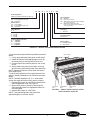
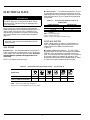
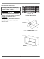
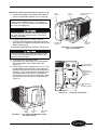
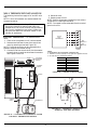
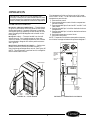
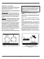
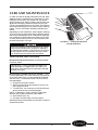
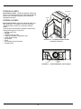
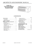
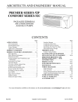
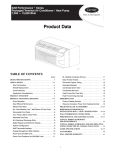
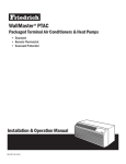
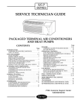
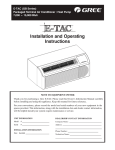
52C 52C
and 52P
SERIES
OWNER’S MANUAL
PACKAGED TERMINAL AIR CONDITIONERS
AND HEAT PUMPS
7,000-15,000 Btuh
CONTENTS
Page
GENERAL. . . . . . . . . . . . . . . . . . . . . . . . . . . . . . . . . . . . . . . 2
UNIT INSPECTION . . . . . . . . . . . . . . . . . . . . . . . . . . . . . 2,3
FRONT PANEL . . . . . . . . . . . . . . . . . . . . . . . . . . . . . . . . 2
ELECTRICAL DATA. . . . . . . . . . . . . . . . . . . . . . . . . . . . . . 4
ALL UNITS. . . . . . . . . . . . . . . . . . . . . . . . . . . . . . . . . . . . 4
VOLTAGE SUPPLY . . . . . . . . . . . . . . . . . . . . . . . . . . . . . 4
INSTALLATION . . . . . . . . . . . . . . . . . . . . . . . . . . . . . . . .5-8
CHASSIS INSTALLATION . . . . . . . . . . . . . . . . . . . . . . 5
WALL THERMOSTAT INSTALLATION . . . . . . . . . . . 8
OPERATION . . . . . . . . . . . . . . . . . . . . . . . . . . . . . . . . . .9,10
COMFORT CONTROLS. . . . . . . . . . . . . . . . . . . . . . . . . 9
OPERATING CONTROLS . . . . . . . . . . . . . . . . . . . . . . 10
OPERATING MODES . . . . . . . . . . . . . . . . . . . . . . . . . . 10
Page
CARE AND MAINTENANCE . . . . . . . . . . . . . . . . . 11,12
INDOOR-AIR INLET FILTERS . . . . . . . . . . . . . . . . . . 11
EXTERNAL PARTS . . . . . . . . . . . . . . . . . . . . . . . . . . . . 12
INTERNAL PARTS. . . . . . . . . . . . . . . . . . . . . . . . . . . . . 12
PREVENTATIVE MAINTENANCE . . . . . . . . . . . . . . . . 13
TROUBLESHOOTING. . . . . . . . . . . . . . . . . . . . . . . . . . . 13
ACCESSORIES. . . . . . . . . . . . . . . . . . . . . . . . . . . . . . . . . . 14
1•800•894•6449 (in USA and Canada)
For Service/Technical Assistance
1•800•830•8600 (Mexico)
Manufacturer reserves the right to discontinue, or change at any time, specifications or designs without notice and without incurring obligations.
PC 132
Catalog No. 535-20038
Printed in U.S.A.
Form 52C,P-1SO
Pg 1
2-02
Replaces: 52C-1SI
Book 1 4
52P-1SO
Tab
9a 11a
GENERAL
with all accessory components. See Accessories section
on page 14 for complete listing of accessories.
Thank you for choosing Carrier! You can feel confident
in your selection because the same pride in craftsmanship and engineering knowledge that goes into Carrier
equipment at the Astrodome in Texas, the Sistine
Chapel in Rome, the US Capitol Hall of Congress, and
thousands of other installations worldwide has gone
into the construction of this unit.
The Carrier package terminal air conditioners and
heat pumps provide a high standard of quality in performance, workmanship, durability and appearance as
they heat and cool the occupied air space year round.
This manual provides information for ease of installation, operation and maintenance of the 52C and 52P
units. The following units are covered in this manual
(see Figure 1 for additional unit information):
52CE 60 Hz cooling with electric heat units
52CQ 60 Hz cooling, electric heat, and heat pump units
52PE 60 Hz cooling with electric heat units
52PQ 60 Hz cooling, electric heat, and heat pump units
52PC 60 Hz cooling only units
All models are designed for through-the-wall installation. Separate installation instructions are included
UNIT INSPECTION
MODEL
FRONT PANEL
To remove the front panel:
1. Grasp panel firmly near bottom of both sides.
2. Pull panel forward then upward to release magnetic latches and partition hooks.
NOTE: Front panel may be secured to chassis with
2 screws located behind indoor air inlet filters. In order
to remove these screws, the filters must be removed
first. Refer to page 10 in this manual for instructions on
removing indoor air inlet filters.
52PQA312301AA
SERIAL
3701X11520
DATE OF MFG.
VOLT RANGE
VOLTS
PH
Examine unit for damage incurred during shipment.
File a claim immediately with the transit company if
damage is found.
The data information plate (Figure 1) lists the model
number, voltage ranges, and other important electrical
information about this product. Reading and understanding this material is important for proper use of
this unit. To access the information plate, the front
panel must be removed; see Figure 2.
IMPORTANT: The front panel has to be off the unit
to complete future checks and installation procedures. Do not reinstall front panel at this time.
09/12/2001
187-253
230/208
HZ
1
60
MIN CKT AMPACITY
R-22 OZ
19.3
34
Using Figures 1 and 3 as reference, verify that the
packaged terminal product ordered will operate properly in your facility. If you do not understand the information given or have questions about the product,
please call your local dealer or distributor.
DESIGN PSIG 350 HIGH SIDE, 150 LOW SIDE
COOLING
BTU/HR
12,100/12,000
AMPS
4.8/5.3
WATTS
1100/1100
EER
11.0/10.9
RLA
6.1
LRA
29
COMP
FAN
FLA
0.75
MOTOR
HP
1/8
HEATING
BTU/HR
AMPS
10,800/10,700
15.6/14.5
WATTS
3570/2997
COP
3.2/3.2
HEATER
BTU/HR
AMPS
14.8/13.7
WATTS
3400/2850
WATER
STEAM
USE
20
AMP CANADIAN INSTALLATION
MAX FUSE MAX BREAKER
TIME DELAY FUSE
OR HACR TYPE
CIRCUIT BREAKER
C
20
AMP
20
AMP
FIGURE 2 — REMOVING FRONT PANEL
US
Replacement Package Terminal Air Conditioner,
CLASSIFIED BY UNDERWRITERS LABORATORIES INC., AS TO ELECTRIC
SHOCK, FIRE AND CASUALTY
HAZARDS ONLY. FOR FIELD
INSTALLATION WITH EXISTING
WALL SLEEVES, OUTDOOR LOUVERS, AND INDOOR PANELS AS
SPECIFIED ON THE PRODUCT.
FIGURE 1 — SAMPLE DATA INFORMATION PLATE
2
52
PE
A
3
12
3
0
1
AA
Series Designation
PTAC (Packaged Terminal Air Conditioner)
Chassis Options
AA – Standard
CP – Corrosion Protection
RC – Wall Thermostat Control (Not available
on cooling only units)
RP – Wall Thermostat Control with
Corrosion Protection (Not available on
cooling only units)
Comfort Series
CE – Cooling with Electric Heat
CQ – Heat Pump
Premier Series
PC – Cooling Only
PE – Cooling with Electric Heat
PQ – Heat Pump
Latest Revision
A– Z
Packaging
1 – Domestic
Electric Heater Size
2 – 2.3 kW
3 – 3.4 kW
5 – 5.0 kW
Non-Performance
Changes 0-9
Cooling Capacity (nominal)
07 – 7,000 Btuh
09 – 9,000 Btuh
12 – 12,000 Btuh
15 – 15,000 Btuh
Electrical Data
3 – 230/208-v, 60 Hz
4 – 265-v, 60 Hz
FIGURE 3 — MODEL NUMBER NOMENCLATURE
To install the front panel follow the procedure outlined
below:
1. Firmly grasp bottom of front panel on both sides.
2. Hold front panel at a 45 degree angle to unit. Be
sure front panel is centered with front of unit.
3. Connect top of front panel to partition rail on top
of unit.
4. Gently lower front panel onto chassis, ensuring
service cord is positioned through front panel slot.
NOTE: Magnets on bottom of front panel will secure
front panel to unit.
To install locking feature on front panel be sure front
panel is already installed on unit and follow the steps
below:
NOTE: Two field-supplied no. 8, 1/2 in. sheet metal
screws are required to secure front panel to chassis.
1. Remove both indoor air inlet filters to expose front
panel engagement holes. See Figure 4.
2. Secure front panel to chassis by attaching the
field-supplied screws into engagement holes. Do
not over tighten.
3. Replace both indoor air inlet filters.
NOTE: Front panel alignment may have to be
adjusted slightly to line with chassis.
TOP PARTITION
DISCHARGE
DECK
ENGAGEMENT
HOLE
FRONT PANEL
SLOT
FIGURE 4 — FRONT PANEL INSTALLATION
WITH LOCKING FEATURE
3
ELECTRICAL DATA
■ GROUNDING — For safety and protection, the unit
is grounded through the service cord plug or through
separate ground wire provided on hardwired units. Be
sure that the branch circuit or general purpose outlet
is grounded.
ELECTRICAL SHOCK HAZARD
DO NOT alter cord or plug, and DO NOT use an
extension cord. Personal injury or damage to the
unit may result.
TABLE 1 — SUGGESTED BRANCH CIRCUIT
WIRE SIZES*
NAMEPLATE AMPS
7.0 to 12
12.1 to 16
16.1 to 24
Be sure that your outlet matches the appropriate
blade configuration of the supplied plug and that it is
within reach of the service cord. A hardwire kit is
available as an accessory to change cord-connected
units to hardwired units. (See Accessories table on
page 14.)
AWG WIRE SIZE†
14
12
10
LEGEND
AWG — American Wire Gage
*Single circuit from main box.
†Based on copper wire at 60 C temperature rating.
IMPORTANT: All standard cord-connected 265-v
units will require a field-installed electrical subbase accessory.
VOLTAGE SUPPLY
Check voltage supply at outlet. For satisfactory results, the voltage range must always be within the
ranges found on the data information plate
(Figure 1).
ALL UNITS
■ CORD-CONNECTED UNITS — The 250-v fieldsupplied outlet must match the plug for the standard
208/230-v units and be within reach of the service
cord. The standard cord-connected 265-v units require
an accessory electrical subbase for operation. See
Accessories table, page 14, for subbase selection. Refer
to Table 2 for proper receptacle and fuse type.
■
WIRE SIZE — Use recommended wire size given in
Table 1 and install a single branch circuit. All wiring
must comply with local and national codes. All units
are designed to operate off single branch circuits only.
NOTE: Use copper conductors only.
TABLE 2 — RECEPTACLES AND FUSE TYPES — 250,265 VOLTS
RECEPTACLE
RATED VOLTS
TIME-DELAY TYPE
FUSE (or HACR Circuit Breaker)
15 Amps
250
20 Amps
250
30 Amps
250
15 Amps
265
20 Amps
265
30 Amps
265
15
20*
30
15
20
30
LEGEND
HACR — Heating, Air Conditioning, Refrigeration
*May be used for 15-amp applications if fused for 15 amp.
4
INSTALLATION
CHASSIS INSTALLATION
Units are shipped without a sleeve. In applications
where unit is a replacement, it is recommended that a
Carrier sleeve be used.
The 52C and 52P units can retrofit General Electric,
Amana, Trane, and Friedrich sleeves/grilles (be sure
outdoor grille is installed on the sleeve). See Table 3
for details. Carrier Corporation must approve any
other retrofit application.
For competitive retrofit applications, be sure that the
foam seals (factory-installed on the tube sheets) provide a good seal between the grille and outdoor coil
tube sheets. These foam seals provide a barrier to separate outdoor coil leaving air from mixing with the
outdoor incoming air (known as air recirculation).
See Figure 5.
For retrofit applications, foam seals on outdoor coil
tube sheets must make a seal between the coil and
the grille or loss of performance and premature
damage to the major components can result.
TABLE 3 — RETROFIT WALL SLEEVES
MANUFACTURER
WALL SLEEVE PART NUMBER
General Electric
Metal Sleeve RAB71
Plastic Sleeve RAB77
Amana
Metal Sleeve WS900B
Trane
Metal Sleeve SLV149
Friedrich
T-Series Metal 111/2-in. deep wall sleeve*
Standard depth wall sleeve 16 x 42 x 133/4-in.
PXWS
*FR-SLEEVE-EXT accessory is required for retrofit into Friedrich
(T-Series) wall sleeves.
INDOOR-AIR
INLET
FILTERS
FRONT
PANEL
DISCHARGE
GRILLE
WIRE SCREEN
OUTDOOR
ORIFICE
INDOOR
COIL
FIGURE 5 — UNIT COMPONENTS
5
COIL TUBE
SHEETS
BASEPAN
OUTDOOR
GRILLE
WALL
SLEEVE
■
RETROFIT SLEEVE PREPARATION
IMPORTANT: Inspect the wall sleeve thoroughly
prior to installation. Manufacturer does not assume
responsibility for costs or damages due to defects in
the sleeve or improper installation.
Disconnect all power to unit to avoid possible electrical shock during installation.
BAFFLES
FIGURE 6 — REMOVE EXISTING
OUTDOOR GRILLE BAFFLES
Remove any existing foam baffles that are installed on
the outdoor grille if present. See Figure 6.
GE Sleeves Only
Metal Wall Sleeve — Remove metal clip on mounting
rail located on left, inside bottom of metal sleeve and
discard. See Figure 7.
Plastic Sleeve — Remove bottom seal from plastic
sleeve. See Figure 8.
FIGURE 7 — REMOVE METAL CLIP ON
GE METAL SLEEVE
FIGURE 8 — REMOVE BOTTOM SEAL FROM
GE PLASTIC SLEEVE
6
■
INSTALL CHASSIS IN SLEEVE (See Figures 9 to 11)
1. Inspect foam gaskets (top, bottom, both sides) on
chassis. Replace foam gaskets if torn or missing.
SIDE
GASKET
TOP
GASKET
FACTORY-INSTALLED
FOAM SEALS
IMPORTANT: The gaskets combine with the sleeve
face to create a weather barrier. If the chassis is
installed in a non-Carrier sleeve, this weather barrier may not be effective.
Chassis weighs up to 150 lbs. For personal protection, seek help when lifting the unit. Lift unit by
holding unit basepan.
2. If retrofitting into a GE, Amana, Trane, or
Friedrich wall sleeve/grille, remove any existing
foam seals from competitive manufacturer’s grille
before installing unit.
3. Remove shipping tape from vent door. See Figure 9.
COIL TUBE
SHEETS
BOTTOM
GASKET
FIGURE 10 — UNIT GASKETS
AND TUBE SHEETS
Failure to remove shipping tape will prevent fresh
air vent door from opening and may result in damage to the vent door cable.
4. Lift chassis level with wall sleeve.
5. Slide chassis into wall sleeve until foam gaskets
rest firmly against front of wall sleeve. See
Figure 10.
6. Screw chassis to wall sleeve with four 13/4-in. long
screws taped to the control box. Screw holes are
located on both sides of the mounting angles of the
chassis. For Carrier wall sleeves, use the top-most
and bottom-most screw holes. For competitive
wall sleeves, line up the correct attachment holes
on the chassis with the holes in the sleeves. See
Figure 11.
TOP SCREW HOLE
(CARRIER SLEEVE)
COMPETITIVE
MANUFACTURER
SLEEVE
ATTACHMENT
HOLES
BOTTOM SCREW
HOLE
(CARRIER SLEEVE)
FIGURE 11 — CHASSIS MOUNTING
VENT
DOOR
SHIPPING
TAPE
VENT DOOR
CABLE
FIGURE 9 — LOCATION OF SHIPPING TAPE
ON VENT DOOR
7
WALL THERMOSTAT INSTALLATION
The following instructions apply to RC and RP units
only.
NOTE: Carrier thermostats are recommended. See
Accessories section.
4. Reinstall cover.
5. Restore power to unit.
NOTE: Refer to thermostat installation instructions
for details on installing thermostat.
NOTE: Fan speed is user-selectable from the control
panel on the unit.
IMPORTANT: Only trained, qualified personnel
and service mechanics should install electrical
accessories on Carrier 52C and 52P series products
per Carrier’s installation instructions. Please contact your local electrical contractor, dealer, or distributor for assistance.
R
G
INSTALL THERMOSTAT — All remote control
units.
1. Check to be sure power to unit is disconnected.
2. Remove terminal board cover from control box
cover by removing screw (see Figure 12).
NOTE: Terminal connector can be removed and replaced to simplify thermostat wiring.
3. Connect wires from terminals on the thermostat
to terminals on chassis terminal board connector.
See Figures 13 and 14.
FAN SPEED
LO
HI
Y
TYPICAL
WALL
THERMOSTAT
■
W
O
SEE
NOTE #1
C
SEE
NOTE #2
TERMINAL
BLOCK
NOTES:
1. Use terminal “O” for heat pump connection only.
2. Terminal C (common) typically is only required for digital thermostats.
3. See table below for terminal descriptions.
TERMINAL
R
G
Y
W
O
C
FAN SPEED
SELECTOR
SWITCH
TERMINAL
COVER
DESIGNATION
24 VAC
Fan
Compressor
Electric Heat
Reversing Valve
Common
FIGURE 13 — WIRING CONNECTIONS
SCREW
R
G
Y
W
O
C
POWER
CORD
THERMOSTAT
FIGURE 14 — TERMINAL CONNECTOR
REMOVAL AND REPLACEMENT
FIGURE 12 — CONTROL BOX TERMINAL COVER
FOR WALL THERMOSTAT MODELS
8
OPERATION
The temperature limits are factory set to full range,
which is 60 F to 90 F. To set restricted rotation of the
temperature control knob:
1. Remove front panel.
2. Remove temperature control knob to expose temperature limiter.
3. Remove standoff pins from the 60 F and 90 F indicator holes.
4. Replace standoff pin in hole for desired minimum
temperature.
5. Replace standoff pin in hole for desired maximum
temperature.
6. Reinstall temperature control knob.
7. Reinstall front panel.
NOTE: Temperature indicators stamped on temperature limiter are approximate and represent degrees F.
IMPORTANT: When unit is first started, high
humidity conditions can cause condensation to form
on discharge grille. Keep doors and windows closed.
Room humidity decreases and moisture evaporates.
COMFORT CONTROLS
■
ADJUST AIRFLOW DIRECTION — The discharge
air grille is mounted on the front panel so that the air
discharges forward. If upward discharge is required,
remove the grille by removing screws on back of front
panel. Rotate grille 180 degrees and reinstall on the
front panel.
■ ADJUST VENT — The vent handle is on the left
side of the unit. Turn handle to open or close vent.
Vent will remain in last desired position until handle
is turned again. Magnet will ensure positive closure.
See Figure 15.
■ SETTING TEMPERATURE LIMITS — Setting temperature limits on the unit provides the user a
restricted range of temperature control. See Figure 16.
NOTE: This adjustment is optional and is not applicable to remote control units.
75
80
70
85
65
90
60
TEMPERATURE
CONTROL
STANDOFF
PINS
CON
FAN CYCLE
SWITCH
CYC
VENT HANDLE
MAGNET
OP
EN
CL
OS
E
SET
SCREW
OUTDOOR
THERMOSTAT
(HEAT PUMP
UNITS ONLY)
VENT
DOOR
VENT
FILTER
FIGURE 16 — OPERATING CONTROLS
FIGURE 15 — VENT DOOR
9
OPERATING CONTROLS
IMPORTANT: If setscrew on standard heat pump
unit is set to electric heat mode operation, the compressor is disabled for both heating and cooling
operations. If setscrew on heat pump unit with wall
thermostat control is set to electric heat mode
operation, the compressor will be disabled only for
heating operation.
The following controls are located on the front of the
control box door, under front panel. To obtain access to
operating controls, remove the unit front panel as
shown on page 2. See Figure 16.
■
FAN CYCLE SWITCH — (Typically available at wall
thermostat on RC or RP units.) This allows the fan to
operate in two modes:
CON (Continuous) — This setting allows the fan to
run continuously, circulating air even when the temperature setting has been satisfied. This switch helps
to maintain the room temperature closer to the thermostat setting. Use this switch position when maximum comfort is desired. This is the factory default
setting.
CYC (Cycle) — This setting allows the fan to cycle on
and off with the compressor during heating or cooling.
The fan stops when the temperature setting is satisfied. This results in longer unit off-time and wider
variations in room temperature and humidity.
OPERATING MODES (See Figures 17
and 18.)
■ OUTSIDE AIR — To bring outside air into occupied
space, turn the vent handle to the full open position.
See Figure 15.
■
OFF — The OFF mode terminates unit operation.
■ FAN— The FAN mode will circulate air in the space
at high speed and at high or low speed for cooling only
models.
■ HIGH HEAT OR HIGH COOL — Select mode and
rotate temperature knob to desired comfort level. This
function provides maximum heating or cooling, and is
recommended to raise or lower the room temperature
quickly.
■
OUTDOOR THERMOSTAT (52CQ and 52PQ HEAT
PUMP UNITS ONLY) — If the setscrew is left at the
factory setting (in the heat pump position), the unit
will operate in the reverse cycle heating mode. See
Figure 16. When the temperature of the outdoor coil
reaches 20° F (approximately 35° F outdoor air temperature), the compressor will shut down. The electric
heater remains on until the temperature of the outdoor coil reaches 40° F; then the electric heater is shut
off and the compressor is energized.
To set unit to operate in electric heat mode only, turn
the setscrew to the electric heat position. See Figure 16.
■
LOW HEAT OR LOW COOL — Select mode and
rotate temperature knob to desired comfort level. This
function provides minimum heating or cooling with
maximum dehumidification and quietest operation.
■
FAN SPEED CONTROL FOR 52P AND 52C WALL
THERMOSTAT MODELS — For maximum comfort,
fan speed is user selectable at the unit. See Figure 18.
FIGURE 18 — 52P UNIT WITH
WALL THERMOSTAT CONTROL SHOWN
(Blank Plate)
FIGURE 17 — 52P UNIT CONTROLS SHOWN
10
CARE AND MAINTENANCE
In order to maintain proper performance of your packaged terminal air conditioner or heat pump, it is very
important that the fan and outdoor coil, the blower
wheel, blower scroll, electric heater, and all drain passages are thoroughly cleaned at least once per year.
Carrier recommends that as a minimum, the cleaning
should be conducted prior to the start of each heating
season. The air inlet filters should be cleaned every
month.
Depending on local conditions, more frequent cleaning
of the unit may be required to ensure optimum performance and long operating life. Examples of these special conditions include areas where construction dust
or heavy airborne dirt is found, or environments that
promote the growth of fungus.
FIGURE 19 — INDOOR-AIR INLET
FILTER REMOVAL
Some local conditions and environments can cause
fungi to grow inside the air conditioner, especially
on indoor blower section. Dried fungi, dirt and other
foreign material are fire hazards. Be sure to clean
unit according to the instructions that follow.
INDOOR-AIR INLET FILTERS
■
INDOOR-AIR INLET FILTERS should be cleaned
once each month.
IMPORTANT: Filters may become clogged if not
cleaned properly. Clogged filters will restrict airflow which may lead to severe component damage
and efficiency loss.
■
CLEANING INDOOR-AIR INLET FILTER — Two
interchangeable air filters are located on the backside
of the front panel. Each can be removed and cleaned
one at a time. To remove and clean the filter, follow
the steps below:
1. Grasp filter with both hands.
2. Gently pull the filter up and away from the unit.
See Figures 5 and 19.
3. To clean filter, use a vacuum or soft bristle brush
with a small amount of mild detergent.
NOTE: If detergent is used, remove any detergent
residual with a gentle stream of clean water.
4. Allow filters to air dry.
5. Re-insert dry filters back into front panel.
Additional filters are available in multi-packs. Refer to
Accessories section.
11
EXTERNAL PARTS
VENT HANDLE
■
EXTERNAL PARTS include the polymer sleeve and
grilles. The sleeve manufacturer recommends cleaning
the surface, including the grilles, with household
detergent and water.
MAGNET
INTERNAL PARTS
OP
■
INTERNAL PARTS should be cleaned at least once
during the year. The outdoor vent filter should be
cleaned at least once during a cooling or heating
season.
Internal parts that should be cleaned include the following (see Figures 5, 20, and 21):
• Outdoor vent filter
• Basepan
• Outdoor orifice and fan
• Indoor and outdoor refrigeration coils
• Indoor blower wheel
• Wire screen
• Scroll
• Wall sleeve internal surfaces
• Outdoor grille
VENT
DOOR
EN
CL
OS
E
VENT
FILTER
FIGURE 20 — OUTDOOR VENT FILTER
(Left Side of Chassis)
SCROLL
BLOWER
WHEEL
FIGURE 21 — BLOWER WHEEL AND SCROLL
12
PREVENTATIVE
MAINTENANCE
Preventative maintenance is essential to proper unit
operation, efficiency and longevity. To assure equipment operates properly it must be properly maintained. Equipment operation should be checked and
verified several times during each year.
During regular unit inspection and maintenance, follow the guidelines below:
• Wash both sides of outdoor coil
• Wash basepan and outdoor vent filter
• Wash the indoor coil
• Clean the blower wheel and front panel
• Clean or install new indoor-air inlet filter(s)
• Ensure knobs are secure and operable
• Inspect cord and receptacle
• Secure electrical connections
• Ensure front panel is properly mounted and not
damaged
• Ensure wall sleeve is installed properly
• Ensure heat and cool cycles operate properly
TROUBLESHOOTING
POSSIBLE CAUSES
UNIT DOES NOT START
• Unit may have become unplugged
• Fuse may have blown
• Circuit breaker may have been tripped
• Unit mode dial may be set to the OFF position
UNIT NOT COOLING/HEATING ROOM
• Unit air discharge section is blocked
• Temperature setting is not high or low enough
• Unit air filters are dirty
• Room is excessively hot or cold when unit is started
• Vent door left open
UNIT MAKING NOISES
WATER DRIPPING OUTSIDE
WATER DRIPPING INSIDE
• Wall sleeve is not installed level
ICE OR FROST FORMS ON INDOOR COIL
• Low outdoor temperature
• Dirty filters
SOLUTIONS
• Check that plug is securely in wall receptacle.
• Replace the fuse. See Note 1.
• Reset circuit breaker. See Note 1.
• Switch mode dial to an operating mode.
• Make sure that curtains, blinds or furniture are not restricting or
blocking unit airflow.
• Reset to a lower or higher temperature setting.
• Remove and clean filters.
• Allow sufficient amount of time for unit to heat or cool the room.
Start heating or cooling early before outdoor temperature, cooking
heat or gatherings of people make room uncomfortable.
• Close vent door.
• Clicking, gurgling and whooshing noises are normal during operation of
unit.
• If a drain kit has not been installed, condensation run-off during
very hot and humid weather is normal. See Note 2. If a drain kit
has been installed and is connected to a drain system, check
gaskets and fittings around drain for leaks and plugs.
• Wall sleeve must be installed level for proper drainage of condensation.
Check that installation is level and make any necessary adjustments.
• When outdoor temperature is approximately 55 F or below, frost
may form on the indoor coil when unit is in Cooling mode. Switch
unit to FAN operation until ice or frost melts.
• Remove and clean filters.
NOTES:
1. If circuit breaker is tripped or fuse is blown more than once, contact a qualified electrician.
2. If unit is installed where condensation drainage could drip in an undesirable location, an
accessory drain kit should be installed and connected to drain system.
13
ACCESSORIES
ACCESSORY
Wall Sleeves
FORM NUMBER
52S-48SI
52S-50SI
52S-49SI
52C,P-20SI
52C,P-11SI
GRILLE-ALU-STAMP
GRILLE-PLA-ALPIN
GRILLE-PLA-BROWN
GRILLE-PLA-BEIGE
GRILLE-ALU-CLEAR
GRILLE-ALU-WHITE
GRILLE-ALU-BRONZ
GRILLE-ALU-MBRNZ
GRILLE-ALU-BROWN
GRILLE-ALU-BEIGE
GRILLE-ALU-ALPIN
GRILLE-ALU-PEACH
GRILLE-ALU-MELON
GRILLE-ALU-LGREY
GRILLE-ALU-SGREY
GRILLE-ALU-RDBRK
GRILLE-ALU-BLUE
GRILLE-ALU-GREEN
SUBBASE-NON-ELEC
SUBBASE-230V-15A
SUBBASE-230V-20A
SUBBASE-230V-30A
SUBBASE-265V-15A
SUBBASE-265V-20A
SUBBASE-265V-30A
SUBBASE-HARDWIRE
SUBBASE-SWITCH
SUBBASE-FUSE-15A
SUBBASE-FUSE-20A
SUBBASE-FUSE-30A
HARDWIRE-KIT-1PK
52C,P-19SI
CONDUIT-INTF-4PK
Condensate
Drain Kit
Wall
Thermostats
52S-53SI
DRAIN-KIT-4PK
N/A
Wall Thermostat
Interface
Retrofit Kit
52C,P-7SI
HH01AD045
TSTATCCBPC01-B
TSTATCCBPH01-B
TSTATCCPAC01-B
TSTATCCPHP01-B
RC-FIELDKIT230HC
Exterior Grilles*
52S-59SI
52S-58SI
PART NUMBER
WALL-SLEEVE-1PK
WALL-SLEEVE-9PK
SLEEVE-INSUL-1PK
SLEEVE-STEEL-1PK
SLEEVE-EXT24-1PK
SLEEVE-EXT26-1PK
SLEEVE-EXT28-1PK
SLEEVE-MOLDING
FR-SLEEVE-EXT
52S-60SI
Subbase
52C,P-1SI
52C,P-2SI
52C,P-17SI
Subbase
Field-Installed
Kits
Electrical
Connections
52C,P-3SI
52C,P-4SI
52C,P-5SI
N/A
N/A
2SPEED-TSTAT-KIT
TSTAT-COVER-6X7
N/A
TSTAT-COVER-7X10
N/A
AIR-FILTER-10PK
Electro-mechanical Wall Thermostat (Heat/Cool and Heat Pump)
Value Series Electronic Thermostat w/Digital display (Heat/Cool Models)
Value Series Electronic Thermostat w/Digital display (Heat Pump Models)
7-Day Programmable Electronic Thermostat (Heat/Cool Models)
7-Day Programmable Electronic Thermostat (Heat Pump Models)
Field-installed wall thermostat retrofit kit to convert a standard 230V Heat/Cool unit to an
RC unit. Wall thermostat sold separately (can be used to convert a cool only unit to RC).
Field-installed wall thermostat retrofit kit to convert a standard 230V Heat Pump unit to an
RC unit. Wall thermostat sold separately.
Field-installed wall thermostat retrofit kit to convert a standard 265V Heat/Cool unit to an
RC unit. Wall thermostat sold separately (can be used to convert a cool only unit to RC).
Field-installed wall thermostat retrofit kit to convert a standard 265V Heat Pump unit to a
RC unit. Wall thermostat sold separately.
Field-installed automatic heat/cool changeover thermostat with 2-speed fan control at thermostat.
Clear plastic locking thermostat cover prevents unauthorized access to thermostat.
Cover for use with non-programmable and electro-mechanical thermostats.
Outside dimensions: 61/2″ x 71/2″ x 215/16″. 1 per pack
Clear plastic locking thermostat cover prevents unauthorized access to thermostat. Cover for
use with programmable thermostats. Outside dimensions: 71/4″ x 93/4″ x 33/8″. 1 per pack
Replacement air filters in package of 10
52C,P-10SI
EM-KIT
Allows unit to be turned on and off from a remote location (includes freeze guard protection)
RC-FIELDKIT230HP
RC-FIELDKIT265HC
RC-FIELDKIT265HP
Replacement
Filters
Energy
Management
Locking Security
Control Door
Lateral Duct Kit
Power Fresh Air Vent
Air/Curtain
Deflector
Touch-Up Paint
DESCRIPTION
Non-Insulated Polymer Wall Sleeve, 1 per pack
Non-Insulated Polymer Wall Sleeve, 9 per pack
Insulated Polymer Wall Sleeve, 1 per pack
Insulated Metal Wall Sleeve, 1 per pack
Extended Metal Wall Sleeve for Deep Wall Applications (24 in. deep), 1 per pack
Extended Metal Wall Sleeve for Deep Wall Applications (26 in. deep), 1 per pack
Extended Metal Wall Sleeve for Deep Wall Applications (28 in. deep), 1 per pack
Molding kit to trim the wall sleeve to the wall
Friedrich wall sleeve extension to retrofit Carrier PTAC unit into Friedrich 111/2″deep
(T Series) wall sleeve. 1 per pack
Stamped Aluminum Exterior Grille, Clear Finish
Polymer Architectural Rear Grille, Alpine (matches Carrier Wall Sleeve)
Polymer Architectural Rear Grille, Brown
Polymer Architectural Rear Grille, Beige
Aluminum Architectural Exterior Grille, Clear Finish
Aluminum Architectural Exterior Grille, White
Aluminum Architectural Exterior Grille, Light Bronze
Aluminum Architectural Exterior Grille, Medium Bronze
Aluminum Architectural Exterior Grille, Brown (Dark Bronze)
Aluminum Architectural Exterior Grille, Beige
Aluminum Architectural Exterior Grille, Alpine (matches Carrier Wall Sleeve)
Aluminum Architectural Exterior Grille, Peach
Aluminum Architectural Exterior Grille, Melon
Aluminum Architectural Exterior Grille, Light Grey
Aluminum Architectural Exterior Grille, Slate Gray
Aluminum Architectural Exterior Grille, Red Brick
Aluminum Architectural Exterior Grille, Blue
Aluminum Architectural Exterior Grille, Green
Non-electrical Subbase
Electrical subbase with factory-installed 208/230V, 15 amp receptacle
Electrical subbase with factory-installed 208/230V, 20 amp receptacle
Electrical subbase with factory-installed 208/230V, 30 amp receptacle
Electrical subbase with factory-installed 265V, 15 amp receptacle
Electrical subbase with factory-installed 265V, 20 amp receptacle
Electrical subbase with factory-installed 265V, 30 amp receptacle
Electrical subbase with factory-installed hardwire kit (230/208V and 265V)
Field-Installable Switch kit for an electrical subbase
Field-Installed Fuse Kit (15 amp) for electrical subbase
Field-Installed Fuse Kit (20 amp) for electrical subbase
Field-Installed Fuse Kit (30 amp) for electrical subbase
Permanent power connection to the unit (includes 36″of flexible conduit and unit-mounted
connector, 230/208V and 265V) 1 per pack
Interface kit for field-supplied conduit to provide permanent power connection
(230/208V and 265V) to the unit. Kit includes Molex connector for easy connect/disconnect.
4 per pack
Attaches to wall sleeve for controlled internal or external disposal of condensate 4 per pack
52C,P-13SI
SECURITY-DOOR
Key-locking security door to prevent access to heating and cooling controls
52C,P-14SI
N/A
52C,P-9SI
52C,P-21SI
LATERAL-DUCT
PWR-VENT-DOOR230
PWR-VENT-DOOR265
DEFLECTOR-1PK
CURTDFL-52CP-1PK
N/A
CARRIER-TOUCH-UP
Ductwork to allow one unit to heat and cool two rooms (plenum plus extension duct and registers)
Power vent with automatic door that opens and closes when the fan turns on and off.(230V)
Power vent with automatic door that opens and closes when the fan turns on and off. (265V)
Lateral air deflector, with individually adjustable louvers, to enhance air circulation, 1 per pack
Curtain deflector for 52C and 52P models — prevents curtains from blowing into
discharge air stream. 1 per pack.
NOTE: Curtain deflector for previous models are also available. Contact Carrier Representative.
Touch up paint for repainting scratches or chips.
*Custom colors are also available.
14
15
NOTE: Service and Maintenance items excluded in this warranty may be covered by
a separate service agreement through the seller at time of purchase.
CARRIER WILL NOT BE RESPONSIBLE FOR:
1. CLEANING REQUIRED PRIOR TO WARRANTY REPAIR.
2. Standard maintenance, cleaning or damage resulting from failure to perform
normal maintenance as outlined in the owner’s manual.
3. Instruction on methods of control and use of air conditioning unit after initial
installation.
4. Damage or repairs needed as a consequence of faulty installation or application. This is the responsibility of the installer.
5. Failure to start due to voltage conditions, blown fuses, open circuit breakers
or any other damages due to the inadequacy or interruption of electrical
services.
6. Damage or repairs needed as a consequence of any misapplication, abuse,
unauthorized alteration, improper servicing or operation.
7. Damage as a result of floods, winds, fires, lightning, accidents, corrosive
environment, or other conditions beyond the control of CARRIER.
EXCEPTION TO CORROSIVE ENVIRONMENT IN ABOVE PARAGRAPH —
Packaged terminal units (52 Series) built with corrosion protection are exempt
from the exclusion — “Corrosive Environment.” The unit model number is
identified on the nameplate with a CP suffix.
8. Reimbursement for replacement parts or repair services which are not supplied or designated by CARRIER and which are specifically covered under
this warranty.
9. CARRIER products installed outside the continental U.S.A., Alaska, Hawaii
and Canada.
10. Shipping damage or damage as a result of transporting the unit. This is the
responsibility of the selling dealer or the authorized Room Air Conditioner
service station.
11. ANY SPECIAL, INDIRECT OR CONSEQUENTIAL PROPERTY OR COMMERCIAL DAMAGE OF ANY NATURE WHATSOEVER. Some states do not
allow the exclusion or limitation of incidental or consequential damages, so
the above limitation or exclusion may not apply to you.
12. Warranty coverage of accessory items (wall thermostats, wall sleeves, etc.).
Catalog No. 530-122 (Rev. 3/02)
This warranty gives you specific legal rights, and you may also have other rights which vary from state to state.
*Authorized independent dealers or service stations are registered with Carrier Air Conditioning through its distributor organization.
ALL WORK UNDER THE TERMS OF THIS WARRANTY SHALL BE PERFORMED
DURING NORMAL WORKING HOURS. ALL REPLACEMENT PARTS, WHETHER
NEW OR REMANUFACTURED, ASSUME AS THEIR WARRANTY PERIOD ONLY
THE REMAINING TIME PERIOD OF THIS WARRANTY.
LIMITATION OF WARRANTIES — ALL IMPLIED WARRANTIES (INCLUDING
IMPLIED WARRANTIES OF MERCHANTABILITY) ARE HEREBY LIMITED IN
DURATION TO THE PERIOD FOR WHICH EACH LIMITED WARRANTY IS GIVEN
AND APPLIES. SOME STATES DO NOT ALLOW LIMITATIONS ON HOW LONG
AN IMPLIED WARRANTY LASTS, SO THE ABOVE LIMITATION MAY NOT APPLY
TO YOU. THE EXPRESSED WARRANTIES MADE IN THIS WARRANTY ARE
EXCLUSIVE AND MAY NOT BE ALTERED, ENLARGED, OR CHANGED BY ANY
DISTRIBUTOR, DEALER, OR OTHER PERSON WHATSOEVER.
LIMITED EXTENDED FOUR-YEAR WARRANTY ON NON-SEALED REFRIGERATION SYSTEM ONLY — During the second through fifth years after date of original purchase, Carrier will, through its authorized servicing dealers and service
stations and free of charge to the end user or subsequent users, repair or replace
any non-sealed system part (motor, solenoid, thermistor, thermostat, relays, switch,
capacitor, overload, drain valve, bulb heater, fan, stator) if defective in material or
workmanship. The replacement part can be new or a remanufactured part at
CARRIER’S sole option. THIS LIMITED WARRANTY DOES NOT INCLUDE
LABOR, user is responsible for labor, including cost of diagnosis of problem,
removal and transportation of the air conditioner to and from the service center, and
reinstallation charges necessary to accomplish repair.
FULL EXTENDED FOUR-YEAR WARRANTY ON SEALED REFRIGERATION
SYSTEM ONLY — During the second through fifth years after date of original purchase, CARRIER will, through its authorized servicing dealers and service stations*
and free of charge to the end user or subsequent users, repair or replace the
compressor, condenser, evaporator or connecting tubing if defective in material or
workmanship. This includes system refrigeration charge. The replacement part can
be new or a remanufactured part as provided at CARRIER’S sole option.
FULL ONE-YEAR WARRANTY — During the first year after purchase, CARRIER
will, through its authorized independent servicing dealers or service stations*, and
free of charge to the user or subsequent users, repair or replace any parts which
are defective in material or workmanship. The replacement part can be a new or
remanufactured part as provided at CARRIER’S sole option.
Carrier
Packaged Terminal
Air Conditioner Warranty
Copyright 2002 Carrier Corporation
Manufacturer reserves the right to discontinue, or change at any time, specifications or designs without notice and without incurring obligations.
PC 132
Catalog No. 535-20038
Printed in U.S.A.
Form 52C,P-1SO
Pg 16
2-02
Replaces: 52C-1SI
Book 1 4
52P-1SO
Tab
9a 11a