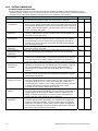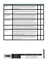
1
INTRUSION/ACCESS/FIRE/INTEGRATED SYSTEM PERFORMANCE SPECIFICATION FOR DMP MODEL XR100 SERIES 1.0 GENERAL 1.1 Manufacturer A. The manufacturer shall have at least twenty-five (25) years of experience in the role of fire and security control manufacturing, and a proven track record of forward and backward compatibility for a minimum of twenty (20) years for its product’s auxiliary devices, including system keypads, annunciation devices, zone expansion modules, and addressable detection devices. B. The manufacturer must also manufacture receiving equipment that is compatible with standard dial-up telephone lines and network monitoring equipment that is compatible with a LAN, WAN, and the Internet. The receiving equipment shall be capable of receiving all status and alarm messages generated by the system. The receiving equipment shall be capable of updating the panel operating program and the system date and time. C. Intrusion detection/Access control panel/Fire Alarm Control Panel (FACP) equipment manufacturer shall be: Digital Monitoring Products, Incorporated (DMP) 2500 N. Partnership Boulevard, Springfield, MO 65803 Telephone (417) 831-9362 FAX (417) 831-1325 1.2 Installer A. The installing company shall show proof of having regular experience with design, installation, service, and maintenance of manufactured systems for a minimum of the last twelve (12) calendar months from the project start date. Each system installer and service person must provide manufacturer certification of technical training for installation, service, and system maintenance. Certification shall be proven with an official document issued by the manufacturer. B. The installing company shall provide a minimum of 8 (eight) verifiable references from its clients where the manufacturer’s system has been installed within the last twelve (12) calendar months from the project start date. C. The installing company shall furnish and install a complete electrically supervised Command Processor™ Panel, as detailed in this specification. The system shall be inclusive of all necessary function, monitoring, and control capability as detailed herein and on accompanying shop drawings. E. The installing company shall become familiar with all details of the work, verify all dimensions in the field, and shall advise the Architect of any discrepancy before performing the work. Materials shall be installed in strict compliance with local building codes. All work shall be performed in accordance with Digital Monitoring Products, Inc. instructions. FACP and associated components must be installed and serviced by a dealer in good standing that is factory-trained by Digital Monitoring Products. 1.3 Central Reporting Station A. The central reporting station contractor must possess an Underwriter's Laboratory (UL) listing as a "Mercantile Police Station" or "Mercantile Burglar Alarm Systems" company. A copy of the listing shall be attached as a part of this bid package. B. The actual alarm signal receipt and processing is a significant portion of the scope of work. Third party and/or contract stations are permitted. UL must list the monitoring station for Protective Signaling Services or Central Reporting Station Signaling Services. A copy of the station UL listing shall be attached as part of this bid package. C. The monitoring station must provide openings/closing activity reports, activity day and time, authorized individual, office name and account number and the system type being monitored. These reports are to be mailed to the user’s office at the end of each month. The Office Manager or Contract Administrator may request an additional report if an incident occurs. D. The contractor must have a valid Alarm Operator License. A copy of licenses shall be attached as part of this bid package. E. The contractor may be required to monitor a portion of the alarm systems by way of the end user data network. F. The Contractor shall become familiar with all work details, verify all dimensions in the field, and shall advise the Architect of any discrepancy before performing the work. G. The end user shall not incur any central station setup charges by the contractor to receive alarm signals by way of the end user data network. XR100/XR100N Intrusion/Access/Fire Detection Specification 1 2.0 SCOPE 2.1 Requirements A. Furnish and install a complete Intrusion Detection/Access Control system or Fire Alarm Control Panel (FACP) with the performance criteria detailed in this specification. The system shall be inclusive of all necessary functions, monitoring, and control capability as detailed herein and on accompanying Shop drawings. On-site or remote video monitoring Heating, air conditioning, and lighting management Temperature threshold detection and monitoring Humidity threshold detection and monitoring Pressure threshold detection and monitoring Power loss detection and monitoring, generator switching Leak detection and monitoring Carbon Monoxide detection and monitoring Tank level threshold detection and monitoring B. This specification document provides the requirements for the installation, programming, and configuration of a complete DMP Panel. This system shall include, but not be limited to: Control panel System cabinet Power supply Digital Signaling Line Circuits (SLC) Notification Appliance Circuits (NAC) Annunciator/keypad bus Batteries Wiring Conduit Associated peripheral devices Other relevant components and accessories required to furnish and install a complete and operational addressable reporting Life Safety System. 2.2 Standards The system shall be listed as a Power Limited Device and be listed under the standards in the table. Each system shall be supplied with complete details on all installation criteria necessary to meet all of the listings. Burglary Listings U.S. Government Standards/Listings UL 1023 Household Burglar Alarm System Units Meets ICD 705 Chapter 7 Intrusion Detection Systems (IDS) UL 1076 Proprietary Burglar Meets DoD/NIST SCIF Standards UL 1610 Central Station Burglar Alarm Units Related Standards UL 1635 Digital Burglar Alarm Communicator System NFPA 70 National Electric Code (NEC) Units Fire Listings NFPA 72 Local Protective Signaling UL 864 Control Units for Fire Protective Signaling NFPA 72 Remote Station Protective Signaling Systems UL 985 Household Fire Warning NFPA 72 Proprietary Protective Signaling California State Fire Marshal NFPA 72 Household Fire Warning New York City FDNY COA #6167 Canadian Burglary Listings Access Control Listings ULC C1023 Household Burglar UL 294 Access Control System Units ULC/ORD-C1076 Proprietary Burglar NIST ULC S304 Central Station Burglar Validated XR100E Encrypted Panel Canadian Fire Listings ULC S545 Household Fire ULC S559 Fire Signal Receiving Centres and Systems 2.3 Americans with Disabilities All indicating and notification appliances shall comply with the Americans with Disabilities Act (ADA) requirements. 2 XR100/XR100N Intrusion/Access/Fire Detection Specification 3.0 SUBMITTALS 3.1 General Requirements The contractor shall submit three (3) complete sets of documentation within thirty (30) calendar days after contract award date. Indicated in the document shall be the manufacturers’ names, catalog number, type, size, style, rating, and catalog data sheets for all items proposed to meet these specifications. 3.2 Shop Drawings Shop drawings shall be submitted in accordance with Section 3.0 Submittals and shall consist of a complete list of equipment and materials, including manufacturer’s descriptive and technical literature, performance charts and curves, catalog cuts, and installation instructions. 3.3 As-Built Drawings The contractor shall provide a complete set of as-built drawings for the entire system upon installation completion. These drawings shall include, but not be limited to, the exact locations of all equipment, connections between all equipment, and wiring for all equipment as the system is installed. 3.4 Spare Parts Data After shop drawings are approved, and not later than thirty (30) calendar days prior to the date of beneficial occupancy, a list of spare parts data for each item of specified materials and equipment shall be submitted. The data shall include a complete list of parts and supplies with current unit prices and source of supply. Spare parts shall consist of, but not be limited to, five (5) percent of all initiating and notification appliances with a minimum of one (1) each. All spare parts shall be on site prior to commencement of acceptance testing. Depleted spare parts shall be replaced prior to beneficial occupancy. 3.5 Operating Documents The contractor shall furnish to the architect operating instructions outlining the step-by-step procedures required for system start-up, operation, and shutdown at least thirty (30) calendar days prior to acceptance test. The instructions shall include the manufacturer’s name, system model number, service manual, parts list, and a description of all equipment and their basic operating features. 3.6 Maintenance Documents The contractor shall furnish maintenance instructions listing routine maintenance procedures, possible breakdowns and repairs, and troubleshooting guides at least 30 calendar days prior to acceptance test. 3.7 Performance Test Reports Upon the installed system completion and testing, test reports shall be submitted in booklet form showing all field tests performed to prove compliance with specified performance criteria. 3.8 Warranty A copy of the manufacturer’s warranty for all equipment and materials shall be provided. Warranty shall be for all equipment, materials, installation, and workmanship for a minimum of three (3) years, unless otherwise specified. XR100/XR100N Intrusion/Access/Fire Detection Specification 3 4.0 GENERAL COMPONENT REQUIREMENTS 4.1 Component Enclosure Housings; power supply enclosures, terminal cabinets, control units, and other component housings, collectively referred to as enclosures shall be so formed and assembled as to be sturdy and rigid. If sheet steel is used in the fabrication of enclosures, it shall be not less than an 18 gauge door with a 20 gauge box frame. Where exposed pins, the hinges shall be of the tight pin type or the ends of hinge pins shall be tack welded to prevent ready removal. Doors having a latch edge length of less than 24 inches shall be provided with a single lock. Where the hinged door latch edge is 24 inches or more in length, doors shall be provided with three-point latching device with lock; or alternatively with two locks, one located near each end. For High Security applications an attack proof enclosure with proper tampers UL listed for use with the XR100/XR100N shall be used. 4.2 Electronic Components A. All system electronic components shall be solid-state type, mounted on printed circuit boards. Light duty relays and similar switching devices shall be solid-state type or electromechanical. B. The panel shall have an over current notification LED that lights when devices connected to the Keypad Bus and LX-Bus draw more current than the panel is rated for. When the over current LED lights, the LX-Bus and Keypad bus are shut down. 4.3 Control Unit A. A battery test shall be automatically performed to test the integrity of the standby battery. The test shall disconnect the standby battery from the charging circuit and place a load on the battery. This test shall be performed no more than every 180 seconds. B. The control unit shall be capable of operating and supervising notification appliance devices as well as addressable initiating detection devices and an integrated supervised dual line digital communicator. C. Control unit must be “Flash ROM” updatable, and program must be held in non-volatile RAM. The panel shall be able to function while the update is in process. 4.4 Remote Annunciators A. The system shall support a maximum of eight (8) supervised remote annunciators with the identical capabilities, functions and display layout. Operation of the remote annunciators shall be limited to authorized users by the use of a code or key. B. The remote annunciators shall be capable of operating at a maximum wiring distance of 15,000 feet from the control unit on unshielded, non-twisted cable. 4.5 Control Designations Controls shall be provided to ensure ease of operation of all specified characteristics. Where applicable, clockwise rotation of controls shall result in an increasing function; controls, switches, visual signals and indicating devices, input and output connectors, terminals and test points shall be clearly marked or labeled on the hardware to permit quick identification of intended use and location. 4.6 Test Function A. The system shall include a provision that permits testing from any alphanumeric keypad. The test shall include standby battery, alarm bell or siren, and communication to the central station. B. The system shall include a provision for an automatic, daily, weekly, thirty (30) day, or up to sixty (60) day communication link test from the control panel installation site to the central station. C. The system shall include a provision for displaying the internal system power and wiring conditions. Internal monitors shall include the bell circuit, AC power, battery voltage level, charging voltage, panel box tamper, phone trouble line 1, phone trouble line 2, transmit trouble, and network trouble. 4 XR100/XR100N Intrusion/Access/Fire Detection Specification 4.7 Power Supplies A. Power supplies for the control unit shall operate from 120 Vac, supplied at the respective protected areas. Standby batteries shall be supplied to power the system in the event of a utility power failure. Batteries shall be sized to provide 105% capacity for eight hours. Standby batteries shall be sealed lead-acid. Power supplies shall be all Solid State. B. Controls shall be designed to maintain full battery charge when alternating current is available. Batteries shall be recharged to 85% capacity within 24 hours from battery use. The system shall be automatically transferred to battery power upon loss of alternating current power and return to alternating current power upon restoration. Intrusion alarms shall not be initiated during switch over; a signal shall be initiated upon failure of battery or alternating current power. C. Approved power supplies shall meet or exceed the following power supply model specifications: UL Listed DMP 505-12: 12Vdc 5 Amp with transformer and enclosure. 4.8 Software A. The system shall interface with computer software with the capability to fully program the panel by connecting to the panel through: Direct cable connection Receiver phone line connection Standard phone line connection Ethernet network connection Network connection across the Internet Cellular network connection using the 463C, 464-263C, 464-263H Cellular Communicators B. The system shall interface with computer software capable of locking down all controlled doors. C. The system shall interface with computer software capable of monitoring and logging all events. D. The system shall interface with computer software capable of exporting reports in the following file formats: Excel spreadsheet (*.xls) Text (*.txt) Rich Text (*.rtf) Comma-separated (*.csv) Windows Metafile (*.wmf) HTML document (*.htm) QuickReport (*.qrp) E. The system shall interface with computer software capable of printing custom, filtered reports including: All Events Door Access Granted Zone Action Door Access Denied Arming/Disarming Opening/Closing Schedule Changes Area Late to Close System Monitors User Code Changes System Events 4.9 Control Panel Capability The basic control panel shall provide: Expansion to a total of at least 10,000 user codes with 99 user profile definitions. Eight (8) independent door/keypad addresses, each with four zones. Twenty (20) Holiday Dates for custom holiday scheduling by area. A total door access granted event buffer of at least 10,000 events. Anti-passback access control selectable by area and user. Four (4) shift schedules per area. A total of at least 100 programmable output relay schedules. Eight (8) individual reporting areas. Built-in bell and telephone line supervision. The networked control panel shall provide: All of the above features. Support programming to require the same or different access code entered within a programmed delay time of 1 to 15 minutes after disarming before activating a silent ambush alarm. Support area programming that disables schedule and time-of-day changes while system is armed so that areas can only be disarmed during scheduled times. XR100/XR100N Intrusion/Access/Fire Detection Specification 5 4.10 Graphic User Interface (GUI) Entré – Access & Security Management Software System Features: A. The software shall be available in three package sizes. Entré Lite™: Shall have 16 doors included, and a maximum of four XR100 Series panels, personnel management, full reports, and event management. Entré Business™: Shall have the same features as Entré Lite with the option of expansion to 96 doors maximum and up to 24 XR100 Series panels. Entré Enterprise™: Shall have the same features as Entré Business with 96 doors included with the ability to expand to an unlimited number of doors, users and XR100 Series panels. B. Shall have simple user management, with the ability to import users from existing databases. C. Shall be able to assign user access by group, facility or other parameters. D. Shall have drop down lists for devices, user data and other information to facilitate fast and accurate searches. E. Shall be able to view system status in one of a variety of views for simplified alarm monitoring management. F. Shall have the capability to customize reports for added flexibility. User Management: A. It shall have the ability to import into Entré from existing systems via standard comma-separated value (CSV) format files. It shall easily add new users, capture and edit their photo for badging or visual verification from within the application. B. User fields shall be fully customizable. Assign specific rights or events by user or by group. The software shall be able to create effective/expiration time for users, limiting access to only certain times of the day, and only certain days, or for only a defined period of time. Highly Customizable: A. The software shall be extensively customizable to create a system that matches the end user’s application’s needs. B. Shall define what events are considered “alarms,” and what response is required from the system operator. C. Shall be able to tailor user data with up to 20 available user-defined fields. Hierarchical Views: A. The software shall have the ability to select from four different system views, with the ability to have multiple views open simultaneously. Select the graphical Map view, tabular Event view, or hierarchical Tree view. B. The software shall be able to click on a device or alert to access additional information and process the event. In text-based views, software shall have simple drill downs to allow fast navigation to the desired item. Powerful Search: The software shall employ industry standard SQL database for quick and easy search to identify any desired device or user which is compatible with nearly any database. Single-System Control: The software shall employ a network solution to manage installations and users from any location. A single, unified database means there’s one badge, one face or one fingerprint, worldwide. 6 XR100/XR100N Intrusion/Access/Fire Detection Specification Entré – Access & Security Management Software Optional System Modules: ENTRE-4DR Additional 4-Doors ENTRE-16DR Additional 16-Doors ENTRE-32DR Additional 32-Doors ENTRE-64DR Additional 64-Doors ENTRE-STD Standard Client ENTRE-WEB Web Client ENTRE-MAPS Alarm Graphics ENTRE-AUTO Automation Module ENTRE-DVR DVR Module ENTRE-PART Database Partitioning ENTRE-LANG Multiple Language module ENTRE-LDAP Lightweight Directory Access Protocol ENTRE-IMAGE Personnel Image Capture ENTRE-BADGE Badge Designer ENTRE-SIGN Signature Capture Optional System Modules Features: A. Shall be able to Point-and-click control of alarms and devices. B. Shall have a modular design to enable customization, with optional modules for added features. C. Shall be available in French, Spanish, or English, with dual- language operation. D. Shall have full reporting, including at-a-glance dashboard graphics and charts or traditional tabular displays, with the ability to produce reports in a variety of file types. E. Shall have DVR integration. F. Shall have image management of users and event photos. G. Shall have a custom badge builder and video badging. Door Modules: The software shall allow for the addition of additional doors to support Entré Business or Enterprise systems. Alarm Graphics: A. The software shall allow for the addition of four more doors to support Entré Business or Enterprise systems. B. Shall have the ability to give graphical representation of events and alarms at-a-glance and give feedback of system status. C. Shall have the capability to upload an unlimited number of graphical images of protected facilities in a variety of file formats. D. System maps are linked from level to level, allowing drill down from a macro view to a specific room or area. E. View alarm status at every level of zoom. F. User-defined layers representing different alarm types allow you to customize the graphical interface to meet application needs. G. Once loaded, it shall have the ability to plot alarm devices on the graphics using drag-and-drop selections from a hierarchical list of hardware. Identify the areas on your site maps, defining them by Classification, Entrances, Zones, and Partitions. H. It shall have total picture-based monitoring and control of the system. It shall from facility-wide views be able to click to zoom in on any area of the facility and view the real-time status of any device. I. The software shall be able to click on the alarm display icon to acknowledge an alarm or to request additional information. XR100/XR100N Intrusion/Access/Fire Detection Specification 7 Automation Module: A. The software shall be able to give advanced users the power to create automated system actions. B. The software shall be able to define automatic responses to any system alarm or events. These include generating a report, generating an alert email, or sending commands to selected devices. C. Shall be able to create scheduled system actions to run once at a specified time and date, or scheduled events that repeat at user defined time and date intervals. D. System automation enables configuration of unattended activities, freeing system managers from many routine responsibilities. DVR: A. The software shall be able to quickly connect to a DVR to review video based on a received alarm from a control panel. B. Connect to DVR from a graphical map of the area to review activity. Verint NetDVR I, firmware 6.47.x or higher NetDVR II, firmware 8.7.x or higher EdgeVR, all firmware versions 3VR E-Series P-Series S-Series ServerClass March Networks™ 3204 Digital Video Recorder (3000 Series) 4000 C NVR (4000 C Series) Dedicated Micros All NetVU compatible series 2 and 3 DVRs Database Partitioning: A. The software shall allow system information to be contained in a single unified database allowing system managers to limit user access to only certain areas of the database to partition the information. B. The software shall allow organization of data into separate collections by physical area, hardware types, events, or other parameters. Multi-Language: A. The software shall support multiple languages enabling multiple operators to select a language during their login process. The software shall allow text shown both in English and a second selected language. B. Available languages shall include: English French Spanish LDAP (Lightweight Directory Access Protocol): A. The software shall provide LDAP single sign-on for users, enabling them to use one password to access multiple system services. B. System user information can be imported directly from an existing LDAP Tree. Badge Image Capture: The software shall allow the transfer of pictures of users from a digital camera directly onto a badge. Select a TWAIN source to capture the image to allow up to date images on employee badges. 8 XR100/XR100N Intrusion/Access/Fire Detection Specification Badge Designer: A. The software shall have the ability to create one or more badge designs, customizing badges by facility, user level, or other parameters. B. When badging employees or visitors, select the desired badge template from library. The template automatically populates with the appropriate data, ready for printing. Signature Capture: Shall use a signature capture device to provide the ability to capture employee or visitor signatures and store the images. Reporting Dashboard: A. The software shall have interactive graphics for instant feedback on system activity. B. The software shall be able to choose a number of charts for functions such as Access Granted / Denied at a particular access point or an entire facility to get a snapshot of activities within any defined time period. C. Shall have ability to filter through user, activity, or event data to narrow results and show precisely the information needed. D. Shall have the ability to view reports from within the application, or saved and exported to PDF, HTML, XLS, CSV, or XML format for distribution. E. Shall automate custom reports to generate and distribute each day at desired times. XR100/XR100N Intrusion/Access/Fire Detection Specification 9 5.0 FUNCTIONAL DESCRIPTIONS 5.1 System Description A. The system areas and zones shall be programmable, and the system shall store, log, display, and transmit specific custom designations for system areas, zones, and user names. B. To ensure continued, one-call support, the system shall be constructed of sensing components provided directly by the system manufacturer, such as power supplies, motion detectors, door and window position switches, glass break detectors, or other sensing devices that the manufacturer offers. C. The system controller, user interfaces, zone input devices, relay output devices, and the system signal receiving equipment shall be engineered, manufactured, assembled, and must be distributed from a location within the United States of America. D. The system shall support user interaction by way of a keypad, web browser, system software, key switch, or radio frequency wireless control, using integrated or auxiliary devices provided by the system manufacturer. E. The system shall support controller zone input connections, system keypads, system zone expansion modules, and wireless zone input modules, and must support zone input connections by way of at least two competitive products. The system shall offer a seamless integrated compatibility with hard-wire and/or wireless zone expansion equipment for at least 100 wireless zones and/or a maximum of 142 hardwired zones. F. The system shall be capable of offering at least one zone expansion bus, which can support the connection of up to 15,000 feet of four-wire cable. Zone expansion and keypad data buses that exceed 2,500 feet of cable must include splitter/repeater modules to boost data voltage and maintain data integrity. G. The system shall provide a seamless capability to provide a minimum of 100 addressable relays, which can be located at any connection location upon a zone expansion bus. H. System relay outputs shall have the capability of being triggered as a result of a command from the user interface, changes in system status, changes in zone status, or by a programmable schedule. I. System relay output states shall be programmable for momentary, maintained, pulsed, or must follow the state of an associated system zone input. J. The system shall be completely programmable either locally from a keypad or remotely through a standard dialup, and network connections by way of a LAN, WAN, and/or by way of the Internet, cellular communications paths. K. The control unit shall be completely programmable remotely using remote annunciators, and/or using upload/download software that communicates using SDLC 300 baud, 2400 baud, or IP Addressed data network. Onsite programming from a personal computer shall also be permitted. L. The control unit shall be equipped with an anti-reversing circuit breaker to prevent damage due to accidental reversal of battery leads. 5.2 Input/Output Capacity A. This system shall be capable of monitoring a maximum of 142 individual zones and controlling a maximum of 102 output relays. B. The control panel shall have, as an integral part of the assembly, 2 SPDT Form C relays rated at 1 Amp at 30 Vdc and four open collector 12 Vdc outputs rated at 50mA each. It shall also have the capacity of a maximum of 25 output expander modules with 100 switched ground, open collector outputs, 50mA maximum and 102 auxiliary relays (Form C rated at 1.0 Amp at 30 Vdc). C. The panel shall also provide 100 programmable output schedules, and include an integral bell alarm circuit providing at least 1.5 Amps of steady, pulsed, or temporal bell output. Output type shall be programmable by zone type. Relays and voltage outputs shall be capable of being independently programmed to turn on and/or off at selected times each day. 10 XR100/XR100N Intrusion/Access/Fire Detection Specification 5.3 User/Authorization Level Capacity The system shall be capable of operation by 10,000 unique Personal Identification Number (PIN) codes with each code having one (1) of ninety-nine (99) custom user profiles. This allows for limitation of certain functions to authorized users. The operation of all keypads shall be limited to authorized users. 5.4 Keypads A. The system shall support a maximum of eight (8) keypads with alphanumeric display. Each keypad shall be capable of arming and disarming any system area based on a pass code or Proximity key authorization. The keypad alphanumeric display shall provide complete prompt messages during all stages of operation and system programming and display all relevant operating and test data. B. Communication between the control panel and all keypads and zone expanders shall be multiplexed over a nonshielded multi-conductor cable, as recommended by the manufacturer. This cable shall also provide the power to all keypads, zone expanders, output expanders, and other power consuming detection devices. C. If at any time a keypad does not detect polling, the alphanumeric display shall indicate "SYSTEM TROUBLE". If at any time two devices are programmed for the same address, the alphanumeric keypad shall display “4 WIRE BUS TROUBLE”. If at any time a keypad detects polling but not for its particular address, the alphanumeric display shall indicate "NON POLLED ADDR". The system shall display all system troubles at selected keypads with distinct alphanumeric messages. D. The keypad shall include self-test diagnostics enabling the installer to test all keypad functions: display test, key test, zone test, LED test, relay test, tone test, and address test. E. The keypad shall provide an easy-to-read English text display. The text shall exactly match the text seen in all software reports, keypad displays, and central station reports. F. The keypad user interface shall be a simple-to-use, menu-driven help system that is completely user friendly. G. The control panel shall support a keypad interface accessible on the World Wide Web in a browser window. The web-accessible keypad interface shall provide at least five (5) programmable hyperlinks for camera access or other use. 5.5 Zone Configuration A. A minimum of 4 Class B ungrounded zones shall be available at each keypad or zone expander on the system. The system shall have the capacity for a maximum of eight (8) keypads and a maximum of 25 four (4) zone expanders or 100 single zone expanders. It shall also have the capacity of a maximum of 25 supervised relay output expanders. All Class B zones shall be 2-wire, 22 AWG minimum, supervised by an end-of-line (EOL) device and shall be able to detect open and short conditions in excess of 500ms duration. B. Each zone shall function in any of the following configurations: Night, Day, Exit, Fire, Supervisory, Emergency, Panic, Auxiliary 1, Auxiliary 2, Fire Verification, Cross Zone, Priority, and Key Switch Arming. C. The digital SLCs and the annunciator/keypad bus shall be able to operate at a maximum wiring distance of 2500 feet from the control panel on unshielded, non-twisted cable. This distance may be extended to a total of 15,000 feet when bus repeater modules are installed. D. Each zone shall function in any of the following configurations: Night Supervisory Auxiliary 1 Cross-Zone Day Emergency Auxiliary 2 Priority Exit Panic Fire Verification Arming Fire XR100/XR100N Intrusion/Access/Fire Detection Specification 11 5.6 Communication A. The system shall be capable of signaling to as many as 8 remote monitoring station receivers. Seven (7) of the eight (8) paths shall be capable of being assigned as either a “primary” or “backup” path. In such a manor the system shall have multiple primary paths to multiple remote monitoring stations as well as multiple backup paths to multiple monitoring stations. B. The system shall be capable of signaling to two remote monitoring station receivers, four telephone numbers of 32 digits each using two separate switched telephone network lines such that if two unsuccessful attempts are made on the first line to the first number, the system shall make two attempts on first line to the second number. If these two attempts are unsuccessful, the system shall make two further attempts on the first line of the first number. After the tenth unsuccessful attempt, dialing shall stop and the alphanumeric keypad shall display trouble. Should another event occur that requires a report to be transmitted, the dialing sequence shall be repeated. The system shall have a programmable option to dial a second set of telephone numbers after the first ten attempts using the same sequence. C. The system shall be capable of communication using the IBM Synchronous Data Link Control format, and at least two other standard industry formats. D. The system shall be capable of supporting Network communication with digital dialer backup, existing Ethernet data networks, satellite communication, fiber optic networks, local area networks, wide area networks, cellular communication, and retail data networks. 5.7 Network Communication A. The control panel shall be capable of asynchronous network communication with a retry time between 3 and 15 seconds for a total of one (1) minute. If communication is unsuccessful the control panel shall be capable of attempting backup communication through any of the available communication methods to the same receiver or a backup receiver. B. The control panel shall employee adaptive communication technology. Adaptive Technology allows a Backup communication path programmed to use Network or Cellular to automatically ADAPT to the faster check-in rate of the Primary path should the Primary path become unavailable, creating a seamless transition for communication of messages. Select Adapt when programming the Checkin option. This allows a system to be fully supervised even if a path fails, while also keeping wireless charges low when the network is good. C. Network communication between the control panel and the receiver shall be in a proprietary communication format. D. The control panel shall be capable of supporting Dynamic Host Communication Protocol (DHCP) Internet Protocol (IP) addressing. E. Underwriters Laboratories (UL) shall list network communication by the control panel for Standard or Encrypted Line Security. F. The control panel shall be capable of two-way network communication using standard Ethernet 10BaseT in a LAN, WAN, or Internet configuration. G. The control panel shall be capable of sending E-mail messaging to up to three E-mail accounts over network communications. H. The control panel shall be capable of sending the following E-mail messages: Zone Alarms by Zone Name AC Power Trouble and Restoral Zone Troubles by Zone Name System Low Battery Zone Bypass by User Ambush Arming (Closings) by User Abort, Cancel and Alarm Verified by User Disarming (Openings) by User Check-in by user Late to Close 12 XR100/XR100N Intrusion/Access/Fire Detection Specification 5.8 Cellular Communications A. The control panel shall have the capability to communicate with a CDMA or HSPA+ plug-in cellular communicator model number 463C, 464-263C or 464-263H that shall plug into the control panel J6 connector which shall supply full data communication and power to the cellular communicator. The cellular communicator shall be capable of communicating full panel alarm and auxiliary messages to the DMP SCS-1R Central Station Receiver as well as E-mail or SMS text messaging to a PC, PDA, or Cellular telephone. B. The control panel shall be capable of sending the following E-mail and SMS messages Zone Alarms by Zone Name AC Power Trouble and Restoral Zone Troubles by Zone Name System Low Battery Zone Bypass by User Ambush Arming (Closings) by User Abort, Cancel and Alarm Verified by User Disarming (Openings) by User Check-in by user Late to Close 5.9 TCP/IP Network Trapping A. The control panel shall be capable of having communication set to Network operation. When a trap is set in Remote Link, the software shall be capable of sending a panel trap message with the panel account number to the SCS-104 installed in an SCS-1R receiver. B. The receiver SCS-104 shall store the trap and monitor the panel for the next message. When the panel sends its next message, the receiver SCS-104 shall then send a message to the panel to contact Remote Link at the IP address contained in the original trap message. C. The trap message shall be stored in the receiver SCS-104 for up to four hours. If the trap message is not sent to the panel within the four-hour window, the panel trap message shall be discarded and a new trap message must be sent from Remote Link. D. The user shall be able to view the trap status of the receiver SCS-104 from Remote Link using the Trap Query function. 5.10 NAC Circuit Configuration A. The system shall be capable of additional Class B NAC circuits utilizing the Model 867 Notification Module. Each module shall be controlled and supervised via the SLC loop and monitor for short circuits, open circuits, and ground faults. The NAC circuits shall monitor for external NAC trouble conditions. B. The system shall be capable of providing Class A NAC circuits utilizing the Model 865 Notification Module. Each module shall monitor for short circuits, open circuits, and ground faults. The NAC circuits shall monitor for external NAC trouble conditions and have a manual bell silence switch. XR100/XR100N Intrusion/Access/Fire Detection Specification 13 6.0 INTEGRATED INTRUSION ALARM AND ACCESS CONTROL OPERATION 6.1 Access Authority Levels The system shall be capable of programming access credentials authority levels to check whether the user has access to a specific area and also has the authority to disarm or arm the area. If the user access credential has access and disarm/arm authority the system shall provide the user the option to disarm the area simultaneously upon opening the door, or to open the door and begin an entry delay timer. With the timer option the user then disarms the area using an intrusion control keypad inside the area. If the user only has access authority to the area and the area is in an armed condition, the user is denied access to the area. 6.2 Door Open Schedule Override The system shall be capable of programming certain area doors to be scheduled to unlock and lock at specific times of the day or night. The lock/unlock function shall be capable of an override option depending upon the area armed/disarmed status. If the area remains in an armed status at the scheduled unlock time the armed status overrides the unlock schedule ensuring the doors remain locked and armed in situations where the business might open late, close early, is affected by inclement weather, or another emergency. 6.3 Common Area The system shall be capable of programming a common area to be armed when the last area in the system is armed and disarmed when the first area in the system is disarmed. To ensure the common area works properly it shall not have any user codes assigned to the common area. The system shall also be capable of programming multiple common areas. 6.4 One-man Walk Test A special code is also available for installers to test the system. The One-Man Walk Test feature allows a single technician to check the panel response to burglary, fire, panic, and supervisory zones. 6.5 Lock Down The system shall for emergency situations, a lock down command can be issued from the keypad menu or via remote command and locks all doors designated as public. 14 XR100/XR100N Intrusion/Access/Fire Detection Specification 7.0 FALSE ALARM REDUCTION FEATURES The system shall be capable of providing false alarm reduction features, functions, capabilities, or processes that either require alarms be verified or potential alarms be corrected before a system or zone can be placed into an armed state. 7.1 Exit Error Alert and Reporting The panel shall be able to provide an automatic function to prevent a false alarm from occurring if an exit door does not properly close after the system is armed. 7.2 Entry and Exit Delay Annunciation A. When arming, the system shall provide clear annunciation indicators to the user about the need to exit the premises prior to the exit delay time expiring. B. When disarming, the system shall notify the user the need to disarm the system prior to the entry delay time expiring. 7.3 Remote Annunciation The system shall be able to provide entry and exit delay time period notification. This notification can be from DMP keypads, remote annunciators, or bell tests. 7.4 Abort Reporting The system shall be capable of sending an Abort report to the central station if the system is disarmed while the alarm is still sounding. The Abort report shall be sent after the alarm report to notify the central station that an authorized user has cancelled the alarm. 7.5 System Testing The system shall offer testing features that are simple, quick, and complete and provide the highest measure of safety by ensuring that alarm conditions are detected and communicated to the proper authorities in a timely manner and on a regularly scheduled basis. 7.6 Ambush Code The system shall offer ambush codes for those dangerous encounters where the user is instructed to either arm or disarm the system under threat of harm. The duress code shall disarm the system without giving local indication of an alarm that might put the user well-being in jeopardy. 7.7 Two-Button Panic Feature The system shall support DMP keypads that provide the option to use only two-button panic codes. The user shall be required to press and hold two designated keys for approximately two seconds before the system generates a panic alarm. 7.8 Fire Verify Zones The system shall support Fire Verify zones to help the panel verify the existence of an actual fire condition before it sends an alarm report to the central station. The Fire Verify zone shall require the panel to perform a Sensor Reset whenever a device connected to a Fire Verify zone initiates an alarm. This shall begin a verification period during which the panel waits for a second alarm initiation. If the original zone or any other Fire Verify zone on the panel initiates an alarm within the next 120 seconds, the panel shall recognize this as an actual alarm and send an alarm report to the central station. 7.9 Cross-Zoning Protection The system shall support cross-zoning as a means of requiring two device trips to occur within a short period of time before sounding an alarm and sending an alarm report to the central station. Supported device trips shall be from one device that trips two times, or from two devices that each trip once. 7.10 Swinger Zone Bypassing The system shall be capable of automatically bypassing a zone if it goes into an alarm or trouble condition a specified number of times within a one-hour period. The panel shall be able to track the number of times the zone trips while armed and compare that against a programmed number. When that number is reached, the panel shall be able to automatically bypass the zone. The panel shall be capable of resetting the zone when the area to which it is assigned disarms, is manually reset from the keypad or remotely, or remains normal for one hour. XR100/XR100N Intrusion/Access/Fire Detection Specification 15 7.11 Recently Armed Report The system shall be capable sending a System Recently Armed report, along with a zone alarm report, to the central station any time an alarm occurs within five minutes of the system arming. The System Recently Armed report allows the central station operator to follow a "call the subscriber first" procedure instead of immediately dispatching the police to what could be a false alarm. 7.12 Transmit Delay The system shall be capable of programming the panel to wait up to 60 seconds before sending burglary alarm reports to the central station. If an alarm is accidental, the user shall be able to disarm the system within the programmed Transmit Delay time. An Abort report shall be sent in place of an alarm report after the system disarms. During the alarm, sirens and panel relay outputs shall not be delayed and shall still provide local condition annunciation. 7.13 Call Waiting Cancel The system shall be capable of being programmed to cancel call waiting any time the panel dials the receiver number to send a report. 7.14 Cancel/Verify The system shall be capable of sending either a Cancel Report or Verify Report to the Central Station to signify that the end user has Canceled an Alarm or Verified an Alarm condition. The system shall be capable of identifying the user by a 16 character name with the cancel or verify report. 16 XR100/XR100N Intrusion/Access/Fire Detection Specification 8.0 Must meet ANSI/SIA CP-01-2010 Standards for False Alarm Reduction The system shall be capable of meeting ANSI/SIA CP-01-2010 Standards for False Alarm Reduction. 8.1 Shall Meet Exit Delay Standards Default – 60 seconds (Minimum 45 seconds) Progress Annunciation – different sound last ten seconds of delay Automatic Restart of running exit delay, one time upon re-entry Recent Closing – signal sent if alarm within 2 minutes of Exit time expiration (change from 5 min) Exit Error – Immediate local alarm and entry delay starts 8.2 Shall Meet Entry Delay Standards Default – 30 seconds (Minimum 30 seconds) Pre-Warning Silenced – after first digit code entry Cancel Message sent if disarmed after alarm sent 8.3 Shall Meet Fail-to-Exit Standards When perimeter and exterior areas are defined and the user does not leave the building before the system arms, the system only arms the perimeter and leaves the interior unarmed 8.4 Shall Meet Automatic Restart Standards The system shall stop the Exit countdown once and restart it to allow the user to pick up a forgotten jacket or briefcase and exit the building without sending an alarm to the central station. XR100/XR100N Intrusion/Access/Fire Detection Specification 17 9.0 FIRE CONTROL SPECIFICATIONS 9.1 FACP Standards The Fire Alarm Control Panel (FACP) system shall be listed as a Power Limited Device and be listed under the standards below. Each system shall be supplied with complete details on all installation criteria necessary to meet all of the listings. Fire Listings Additional Listings UL 864 Control Units for Fire Protective Signaling NFPA 70 National Electric Code (NEC) Systems UL 985 Household Fire Warning NFPA 72 Local Protective Signaling Related Standards NFPA 72 Remote Station Protective Signaling California State Fire Marshal NFPA 72 Proprietary Protective Signaling New York City FDNY COA #6167 NFPA 72 Household Fire Warning Canadian Fire Listings ULC S545 Household Fire ULC S559 Fire Signal Receiving Centres and Systems 9.2 Keypads The system shall include a menu selected "SENSOR RESET" option. This option, without disarming and re-arming the fire system, with use of any pass code, shall reset smoke detectors after they have been tripped. 9.3 Zone Configuration A. The FACP system shall have a minimum of two (2) Class B ungrounded 2-wire smoke detector zones available from the control panel. B. The system shall be capable of providing a maximum of 102 independent, 2-wire, and 12 Vdc powered zones to power smoke detectors. C. Zones on the digital SLC shall support the CleanMe™ feature in Sentrol® smoke detectors that causes the smoke detector to send a message to the control panel when detection capability has deviated from the approved sensitivity range or has failed its internal diagnostic test. 9.4 Fire Annunciators A. The FACP system shall support remote fire annunciators that offer one-button silencing of alarms, reset sensors, testing of the system, and performing of fire drills. These one-button operations shall be protected with a keyswitch on the annunciator. B. If at any time a remote annunciator does not detect polling from the intrusion detection/access control or FACP, the remote annunciator shall indicate “SYSTEM TROUBLE” on its alphanumeric LCD display within 200 seconds. If at any time the remote annunciator detects polling, but not for its particular address, the alphanumeric display shall indicate “NON-POLLED ADDR”. C. The control unit shall be completely programmable remotely using remote annunciators, and/or using upload/download software that communicates using SDLC 300 baud, 2400 baud, 9600 baud, or IP Addressed data network. On-site programming from a personal computer shall also be permitted. Programming changes shall comply with NFPA 72 for acceptance or re-acceptance testing. 9.5 Annunciation Lamps/LEDs Visual Annunciators used on Annunciator modules and elsewhere throughout the system shall be either electric lamps or light emitting diodes (LEDs or LCDs). Annunciators shall be so connected in the circuit that Annunciator failure, socket or protective circuitry shall not result in an improper or indeterminate signal. Lamps of varying types, voltage, and wattage shall have bases and sockets that prevent incorrect replacement. 9.6 Fire Control Equipment Fire Control detection equipment shall communicate to the system by way of the control panel loop expansion bus or 900MHz bi-directional spread spectrum receiver. The detection equipment shall have a three (3) year warranty and meet or exceed features offered in the products listed in Section 12.0 of this document. 18 XR100/XR100N Intrusion/Access/Fire Detection Specification 10.0 BURGLARY CONTROL SPECIFICATIONS 10.1 Burglary Standards The Burglary system shall be listed as a Power Limited Device and be listed under the standards in the table below. Each system shall be supplied with complete details on all installation criteria necessary to meet all of the listings. Burglary Listings U.S. Government Standards UL 365 Police Connect Burglar Meets ICD 705 Chapter 7 Intrusion Detection Systems (IDS) UL 609 Local Burglar Meets DoD/NIST SCIF Standards UL 1023 Household Burglar Alarm System Units Meets ANSI/SIA CP-01-2010 False Alarm Reduction UL 1076 Proprietary Burglar Canadian Burglary Listings UL 1610 Central Station Burglar Alarm Units ULC C1023 Household Burglar Alarm System Units UL 1635 Digital Burglar Alarm Communicator System ULC/ORD-C1076 Proprietary Burglar Units ULC S304 Central Station Burglar Alarm Units 10.2 Area System A. The system user shall be capable of selectively arming and disarming any one or more of eight (8) areas within the intrusion detection system based on the user PIN code and/or keypad used. Each of the 142 zones shall be able to be assigned to any of the eight (8) available areas. The system shall be capable of having up to a sixteen (16) character length name programmed for each area. B. The system user shall be capable of assigning an opening and closing schedule to all areas or to each of the eight (8) areas separately. Each area shall be able to arm or disarm automatically by a schedule. The system shall have the capacity for common areas that automatically disarm when any other area disarms and that automatically arm when all others areas arm. 10.3 Home/Sleep/Away The system shall be capable of being configured in a Home/Sleep/Away configuration for Residential applications. The system shall consist of a Main House system and up to two Guest House systems within one single control Panel with each house being controlled with its own keypad as if it were separate alarm systems. 10.4 All/Perimeter The system shall be capable of being configured into the All/Perimeter configuration to enable the selective arming of both the interior and perimeter when armed “All” or arming just the perimeter devices if arming “Perimeter”. 10.5 Zones The system shall have a minimum of eight (8) grounded burglary zones available from the control panel, and two floating ground powered zones for two wire type compatible smoke detectors. The system shall have the ability to expand using the panel’s keypad bus for up to sixty-four additional zones. The system shall also have a built-in zone expansion bus (LX-Bus) for an additional 100 zones of expansion. The system shall be able to expand up to 400 additional hardwire zones using the 461 interface adaptor and additional 481 (LX-Bus) expansion modules or the ability to integrate up to 500 wireless zones for a total of 574 zones overall. Additional expansion shall be available using the 463C, 464-263C or 464-263H Cellular Communicator which provides for a combination of up to 100 protection zones or 100 relay outputs. 10.6 Burglary Equipment Burglary detection equipment shall communicate to the system by way of the control panel loop expansion bus or 900MHZ bi-directional spread spectrum receiver. The detection equipment shall have a three (3) year warranty and meet or exceed features offered in the products listed in Section 12.0 of this document. XR100/XR100N Intrusion/Access/Fire Detection Specification 19 11.0 ACCESS CONTROL SPECIFICATIONS 11.1 Access Control Standards The access control system shall be listed as a Power Limited Device and be listed under the standards in the table below. Each system shall be supplied with complete details on all installation criteria necessary to meet all of the listings. Access Control Listings U.S. Government Standards UL 294 Access Control System Units Meets ICD/ICS 705 Chapter 7 Intrusion Detection Systems (IDS) Meets DoD/NIST SCIF Standards 11.2 Keypad A. The system shall display a message at any keypad when any system area remains disarmed past the scheduled closing time. The message shall be displayed at one minute past the scheduled closing time. A pre-warn tone shall also begin sounding. If the system is not armed or a schedule extended within ten minutes past the scheduled closing time, the system shall provide the option of sending a Late To Close report to the central station. B. The keypad shall include a door strike relay capable of sending a report to the central station when activated. C. The keypad shall be capable of proximity arming and disarming functions. D. The keypad shall annunciate when canceling an alarm condition the words “Cancel” or “Verify” to allow the end user the ability to cancel a user generated alarm or to select verify to send a message to the central station that the alarm has been verified by the end user and to send emergency response personnel. This is to comply with Alarm Verification. 11.3 Area Access Control The system shall be capable of integrating area access control capability where specified into the same control panel with the ability to have up to 10,000 user credentials. User access is limited to custom profiles and/or schedules. Anti-passback shall be available. The system shall support up to eight (8) access doors, connected to the system using a manufacturer-approved interface module. Area door access products shall meet or exceed features offered by the following products: Keypad reader/administration device – DMP Model 7063/7063A, 7073/7073A, 7163/7173, 7872, 7873 Wiegand Interface – DMP Model 734, 734N, or 734N-WIFI Reader – DMP Model PP-6005B, Model PR-5455, Model MP-5365 Cards or credentials – DMP Model 1326, DMP Model 1306P, DMP Model 1346, DMP Model 1386 11.4 Access Control Equipment Access Control equipment shall communicate to the system by way of the control panel keypad bus. The equipment shall have a three (3) year warranty and meet or exceed features offered in the products listed in Section 12.0 of this document. 20 XR100/XR100N Intrusion/Access/Fire Detection Specification 12.0 MANUFACTURER APPROVED PERIFERALS 12.1 Hard-wired Hard-wired detection equipment shall communicate to the system by way of the control panel loop expansion bus. The equipment shall have a three (3) year warranty as stated in the current DMP Product Catalog and meet or exceed features offered in the following products: Optex Model Motion Detectors (PIR) CX-702 (adjustable pattern 70’ x 70’ or 150’ x 8’) DX-40 40’ x 40’, DX-60 60’ x 60’, MX-40 40’ x 40’ Microwave Detectors EX-35T (adjustable pattern 36’ x 36’ or 60’ x 6’) FX-360 (360° coverage) KX-08 (ceiling mount) RX-40PI (with pet immunity 40’ x 40’) SX-360Z (extra long range with 360° coverage) Sentrol Model Motion Detectors (PIR) PI6000 Sharpshooter™ (with pet immunity) Door Contact DMP Model SD70 (concealed applications – requires DMP zone expander) DMP Model SM20WG (surface applications – requires DMP zone expander) Expansion Modules Bus Splitter/Repeater Module – DMP Model 710 Output Expansion Module - DMP Model 716 Graphic Annunciator Module - DMP Model 717 Other product types shall connect directly to zone expansion modules such as: Manual Fire Alarms – DMP Models 850S, 850D Addressable - DMP Model 711 Addressable - DMP Models 714, 714-8, 714-16 Addressable - DMP Models 712-8 Addressable - DMP Models 715, 715-8, 715-16 Addressable - DMP Models 521LX, 521LXT, 850S/711, 850D/711, 2W-BLX, 2WT-BLX Non-Addressable - DMP Models 521B, 850S, 850D 12.2 Wireless Wireless detection equipment shall communicate to the system by way of a compatible 900MHz receiver utilizing two way communications, capable of receiving up to 100 wireless zones. The wireless system shall be programmed directly from the control panel, and shall not require a separate device programmer. The wireless detection equipment shall have a one (1) year warranty. It shall be capable of sending transmitter and battery status to the control panel’s compatible receiver up to once every 60 seconds and must meet or exceed the following products: Wireless Receiver – DMP Model 1100X-W or 1100XH-W Wireless Repeater – DMP Model 1100R-W Universal transmitter – DMP Model 1101-W, 1102-W Universal Transmitter – DMP Model 1103-W Universal Transmitter – DMP Model 1105-W Wireless Window Transmitter – DMP Model 1107-W Wireless Zone Expander – DMP Model 1114-W Wireless Relay Output – DMP Model 1116-W Wireless LED Annunciator – DMP Model 1117R-B or 1117R-W Wireless Remote Indicator Light – DMP Model 1118R-B or 1118R-W Wireless Door Sounder – DMP Model 1119-W Motion Detector – DMP Model 1121-W, 1125-W, 1126R-W, 1126C-W, 1127W-W, and 1127C-W Glass Break Detector – DMP Model 1129-W Recessed Contact – DMP Model 1131-W Bill Trap – DMP Model 1139-I Panic Transmitter – DMP Model 1142-B, 1142-W, 1142BC-B, 1142BC-W Pendant Panic Transmitter – DMP Model 1145-1-B, 1145-2-B, and 1145-4-B Smoke Detector Transmitter – DMP Model 1161-W, 1162-W Wireless Smoke Detector – DMP Model 1165-W, 1165H-W, 1165HS-W Wireless Post Indicator Valve (PIV) – DMP Model 1181-R Wireless Outside Screw and Yoke Valve (OS & Y) – DMP Model 1182-R Wireless Heat Detectors 1183-135F and 1183-135R Wireless Carbon Monoxide Detector 1184-W XR100/XR100N Intrusion/Access/Fire Detection Specification 21 12.3 Notification Devices Notification equipment shall be control panel activated by way of the supervised bell output module. The equipment shall have a three (3) year warranty as stated in the current DMP Product Catalog and meet or exceed features offered in the following products: Bells – Wheelock Model MB-G6-12, MB-G10-12 Horns – Wheelock Model MT-12/24 Strobe – Wheelock Model RSS-121575W-F, RSSP-121575W-F Horn Strobe – Wheelock Model NS-121575W-F Notification/Synchronization Modules – Wheelock Model SM-12/24-R. DSM-12/24-R Note: If using an external NAC power supply, use devices listed for that particular power supply. 12.4 Power Supplies and Transformers Power supply, transformer, and battery devices shall maintain system operation. The batteries shall be checked and replaced every three to five years. The equipment shall have a three (3) year warranty as stated in the current DMP Product Catalog and meet or exceed features offered in the following products: Power Supply – DMP Model 505-12, 115 Vac, 12 Vdc Power Supply – DMP Model 505-12LX, 115 Vac, 12 Vdc Power Supply – DMP Model 505-12L 12 Vdc Transformer - DMP Model 327, 16.5 Vac 50 VA, Plug-in Transformer - DMP Model 322, 16.5 Vac 56 VA, Wire-in Transformer - DMP Model 323, 16.5 Vac 56 VA, Wire-in Transformer – DMP Model 324, 16.5 Vac 100 VA, Wire-in Transformer – DMP Model 324P, 16.5 Vac 100 VA, Wire-in 12.5 Access Control Equipment Access control equipment shall provide access control functions between the panel and controller door access points. The equipment shall have a three (3) year warranty as stated in the current DMP Product Catalog and meet or exceed features offered in the following products: Interface Module – DMP Model 734, 734N, or 734N-WIFI Wiegand Interface Module Egress Module – DMP Model PB-2 REX Button Reader – DMP Model PP-6005B Proxpoint Plus© Reader – DMP Model MP-5365 Miniprox© Reader – DMP Model MX-5375 Maxi-Prox™ Reader – DMP Model TL-5395 Thinline II™ Door Controller – DMP Model 1306P Prox Patch™ Door Controller – DMP Model 1306PW Prox Patch™ Access Card – DMP Model 1351 ProxPass© Card Access Card – DMP Model 1326 Proxcard II© Card Access Device – DMP Model 1346 Proxkey II™ Keyfob, 1386 Isoprox II© 12.6 Cellular Communications Equipment Cellular Communications equipment shall plug directly into the XR100 J6 connector and shall be supervised by the XR100 Control Communicator. The Cellular Communications Equipment shall be of a low current draw and powered directly by the XR100 Control Communicator. The Cellular Communicator shall communicate in the SDLC Serial 3 Format for communications directly to a SCS-1R DMP Central Station Receiver. The equipment shall have a three (3) year warranty as stated in the current DMP Product Catalog and meet or exceed features offered in the following products: 463C CDMA Cellular Communicator 464-263C CDMA Cellular Communicator 464-263H HSPA+ Cellular Communicator 376 DC Plug-in Power Supply 380-400 Level 400 SIM Card (464-263H only) 381-12 12’ Coax Extension 381-25 25’ Coax Extension 383 Rubber Duck Antenna 386 Wall Mount Antenna Bracket 387-1 3DB Fiberglass Antenna w/Bracket 387-3 3DB MEG Antenna 387-4 SMA to N Cable, 4ft 387-25 SMA to N Cable, 25ft 387-50 SMA to N Cable, 50ft 22 XR100/XR100N Intrusion/Access/Fire Detection Specification 13.0 INSTALLATION 13.1 System Component Installation A. When used in NFPA 72 compliant installations, the Intrusion Detection/Access Control or FACP shall be on an electrical circuit dedicated branch in accordance with the National Electrical Code (NEC) and the local authority having jurisdiction (AHJ). This circuit shall be available only to authorized personnel and shall be clearly labeled “FIRE ALARM CIRCUIT CONTROL”. B. Materials shall be installed in strict compliance with all local, state, county, province, district, federal and other applicable building, safety, and fire standards, laws, codes, regulations, and guidelines including, but not limited to, all appendices and amendments and the requirements of the local authority having jurisdiction (AHJ). 13.2 Lightning Suppression The system shall include an optional lightning suppressor module that intercepts and directs lightning, transient, and RF interference to ground. XR100/XR100N Intrusion/Access/Fire Detection Specification 23 14.0 SYSTEM COMPARISON 14.1 Basic Comparison Items Table The table below lists features or points found necessary for successful installation and continued service of an integrated system. Compare your current system with the listed items. Please provide a certification document providing a clear and truthful statement that agrees with your response to each question. Important Points Explanation Response Made in USA Is your system engineered, designed, manufactured, assembled, and Yes No distributed from a location within the United States of America? Forward and Backward Because we want to preserve a maximum portion of our investment over Yes No compatibility time, can your system manufacturer certify that its has practiced forward and backward compatibility of main system components such as the panel, keypads, zone expansion devices, and relay output devices for a minimum of the last twenty (20) years? Manufacturer Because we require extensive manufacturing experience, has your system Yes No Experience controller manufacturer’s primary role been in the security industry for a minimum of twenty (20) years? System Messaging We require the maximum capabilities in communication offered by the Yes No Compatibility manufacturer. Does your system controller manufacturer also engineer, and manufacture a receiver that receives all messages in less than six seconds? If so, can this receiver receive each and every status message that the controller sends? Experience in Network Has your manufacturer been providing TCP/IP network monitoring for a Yes No Monitoring minimum of fifteen (15) years? Proven success in Does your manufacturer have at least 15,000 installed systems which use Yes No Network monitoring network monitoring to report messages by way of a TCP/IP network? capabilities. No Invasive systems on Because our network is so important to the operation of our business, We Yes No our network require that no additional PCs or terminals be allowed upon our network. Does your manufacturer require additional software or PC terminals in order to program or maintain operation of network monitoring functions? Network monitoring Because we require confirmation of the fitness of your monitoring Yes No flexibility and capabilities, the system must be listed by approved compliance agencies. compliance Can your manufacturer’s controller provide UL Grade AA network monitoring over a network that uses either DHCP, NAT, or a static IP address? Easy operation Because we manage so many people, the system must be easy to operate. Yes No Does your system manufacturer offer keypads with integrated proximity identification capabilities? Seamless Integration Because we are aware of false alarm activations that may occur when using Yes No with Access Control a security system and access control system, we require that these two systems be designed into one control panel. Does your system offer intrusion detection and door access control functions that allow the user to disarm selected areas, and open an access door with a single presentation of a proximity identification device? Distribution of relay Because we intend to integrate this system with many of our other Yes No outputs electronic systems within the building, we require that the placement of triggering relays be as flexible as possible. Does your system have the ability to provide relay outputs in a central location, and distributed across a data bus which extends at least 15,000 feet? Relay triggering Because we intend to integrate this system with many of our other Yes No capabilities electronic systems within the building, we require that the triggering of relays be as flexible as possible. Can your system trigger relay outputs based upon zone status or system status, and can relays be triggered by way of keypad commands, software commands, Web browser commands, RF remote, and a pre-determined schedule? 24 XR100/XR100N Intrusion/Access/Fire Detection Specification Relay associations to zones based upon system and zone states. Common descriptions for zone, area, and user designations. Flexible user interface capabilities Economical system additions for access control Contractor experience Response Yes No Yes No Yes No Yes No Yes No Yes No Yes No 14175 Relay states according to the state of the zone input Explanation Because we intend to integrate this system with many of our other electronic systems within the building, we require that the triggering of relays be as flexible as possible. Can your system’s relay outputs be selected for status to follow zone input status, pulsed output, and maintained outputs. Because we intend to integrate this system with many of our other electronic systems within the building, we require that the triggering of relays be as flexible as possible. Can your system’s relay outputs be configured for different responses based upon the armed state of the zone? Because we intend to integrate this system with many of our other electronic systems within the building, we require that the triggering of relays be as flexible as possible. Can you assign different relays for each zone based upon whether the system is armed and the zone is open, the system is disarmed and the zone is open, the system is armed and the zone is shorted, and the system is disarmed and the zone is shorted? Because we wish to minimize confusion in various ways that we use reporting, we require that descriptions for areas of our building, users of the system, and zone inputs connected to the system offer at least sixteen (16) characters to maximize user understanding. These descriptions must be programmed and stored in one location, and appear exactly the same in stored events, printed logs, and appear remotely at the central monitoring station. Does your system provide this capability? Because we may use the system from many locations, in many ways, we require that the system offer user interface capabilities from local keypads, web browsers, software packages, radio frequency remote arming stations, and must also offer the capability to use any zone input for arming and disarming. Does your system offer all of these capabilities? Because we are looking for a cost-competitive system design, the system shall be capable of adding up to eight (8) door access locations without requiring additional control panels. To minimize cabling costs, the system wiring must support a single four-wire cable to connect up to eight (8) doors, and must use remote intelligent devices to collect door status, user identification devices, and triggers to unlock distant doors. Does your system offer this capability? Because we require that the installing company is experienced and factory trained. We require each installer and service person who works on our system to be factory trained and must submit a certificate issued by the factory as proof of this training. Can your company provide these certification documents? LT-0950 © 2014 Digital Monitoring Products, Inc. Important Points Relay states when triggered