1
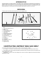
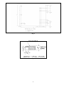
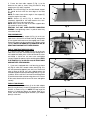
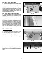
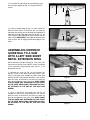
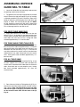
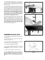
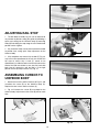
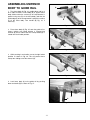
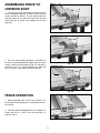
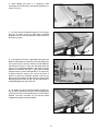
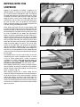
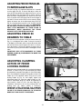
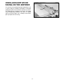
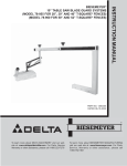
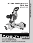
(Model 36-902)
PART NO. 422-27-655-0068 - 02-14-03
Copyright © 2003 Delta Machinery
To learn more about DELTA MACHINERY
visit our website at: www.deltamachinery.com.
For Parts, Service, Warranty or other Assistance,
please call
1-800-223-7278 (In Canada call 1-800-463-3582).
INSTRUCTION MANUAL
Unifence™ Saw Guide
30" Capacity
INTRODUCTION
The model 36-902, 30" capacity Unifence™ Saw Guide can be assembled to the, Contractors Saw and Unisaw, in
addition to other makes of table saws. The 36-902 Unifence Saw Guide includes the fence, carriage assembly, front
guide rail, table frame and legs. The accessory 36-893 table for the 36-902 30" Unifence, is not included and must be
ordered separately or a similar table must be constructed by following the instructions in this manual.
UNPACKING
Carefully unpack the Unifence and all loose items from the shipping cartons.
2
3
7
6
4
8
5
16
1
10
12
11
17
13
9
14
15
Fig. 1
1.
2.
3.
4.
5.
6.
7.
8.
9.
10.
11.
12.
13.
14.
15.
16.
17.
Rail
Front Table Support Bracket (1)
Fence
Unifence Body
Table leg Support Bracket
Table Adapter Plate
Table Leg (2)
Rear table support bracket
1/4-20x2" Flip stop bolt
Flip stop bracket
5/16-18x1" Hex head bolt
Flip stop
Flip stop knob
1/4-20 Nut
Flip stop fiber washer (2)
Unifence cursor
Angle bracket (5)
14
11
10
15
12
13
9
CONSTRUCTING UNIFENCE TABLE AND SHELF
If you purchased the Unifence without the table, a table must be constructed, as follows:
1. A 32" long by 27" wide table is constructed using 3/4" material by following the dimensions shown in Fig. 2.
2. Three undercuts must also be made on the bottom left end of the table. The location and size of the undercuts are
shown in detail in Figs. 2 and 3.
3. IMPORTANT: For maximum ease when sliding the fence across the table we suggest that the top of the table be
covered with a veneer.
2
Fig. 2
Fig. 3
3
ASSEMBLING TABLE
TO SAW
1. If your saw has a right extension wing, front and rear
guide rails, they must be removed.
2. Lay the table upside down on the floor or bench, as
shown in Fig. 4.
Fig. 4
3. Assemble the two table legs (A) Fig. 5 to the bottom
of the table using eight #8x7/8" self tapping screws
supplied. NOTE: Refer to Fig. 2 for the hole location for
the 36-902 30" Unifence.
A
Fig. 5
4. Insert foot adapter (T) Fig. 6, into the bottom of each
leg (A). Assemble the 3/8" jam nut (V) approximately 3/4
of the way onto leveling screw (W). Thread the leveling
screw (W) into foot adapter. Fig. 7 illustrates the foot
leveling assembly on the table leg. Assemble the
remaining foot assembly to the other table leg in the
same manner. NOTE: Height adjustments can be made
later.
4. Assemble table leg support bracket (B) Fig. 8, to the
table legs (A) using two U-clamps (C), flat washers, and
hex nuts.
Fig. 6
A
C
B
Fig. 8
Fig. 7
4
5. Fasten the front table support (F) Fig. 9, to the
bottom of the table as shown using two #8x7/8" long
wood screws (H) and (I) supplied.
NOTE: The vertical flange, on the table board support
(F), should be flush with the front edge of the table
board.
NOTE: The slots closer to the angles in the support (F)
should be against the table.
NOTE: Screws (H) and (I) Fig. 9 should not be
completely tightened to the table board at this time.
Screw (I) will have to be removed later.
NOTE: Make certain the end of the table support does
not extend out past the table.
CAUTION: DO NOT OVER-TIGHTEN MOUNTING
SCREWS. Over-tightening screws in particle board may
cause them to strip.
H
F
I
Fig. 9
I
D
FOR UNISAWS ONLY
6. Fasten the rear table support (A) Fig. 10, to the saw
table. Insert a 3/8-24x5/8" hex head screw (B), through hole
in rear support and thread screw into tapped hole in table.
Repeat this process for the remaining hole. Tighten screws
securely. NOTE: FLAT EDGE (D) Fig. 10 AND FIG. 10A, OF
REAR TABLE SUPPORT WILL FACE UPWARD.
A
B
C
B
FOR 10" CONTRACTORS SAWS ONLY
6. Fasten the rear table support (A) Fig. 10, to the saw
table. Insert a 3/8-16x1" hex head screw (B), through hole in
rear support and table, place a 3/8 washer onto the screw
and thread a 3/8-16 hex nut onto screw and tighten
securely. Repeat this process for the remaining hole. NOTE:
FLAT EDGE (D) Fig. 10 AND FIG. 10A, OF REAR TABLE
SUPPORT WILL FACE UPWARD.
Fig. 10
D
W
7. If your saw is equipped with a cast iron wing as shown
at (I) Fig. 10. which has a smooth surface, hole (C) Fig. 10 is
not used, proceed to step 8. If your saw has a sheet metal
wing as shown at (W) Fig. 10A, with a ribbed surface, the
rear table support will be fastened through hole (C) Fig. 10A
as follows. Insert a 3/8-16x1" hex head screw through hole
(C) and the sheet metal extension wing, place a 3/8" washer
on the screw, thread a 3/8-16 hex nut on screw, and tighten
securely.
A
B
B
C
Fig. 10A
FOR ALL TABLE SAWS
8. Assemble the three brackets (J) to the table adapter
plate (K) using the three 1/4-20x3/4" carriage bolts, nuts and
washers, as shown in Fig. 11. NOTE: The long leg of the
brackets (J) should be against the adapter plate (K) as
shown. Do not completely tighten brackets (J) to adapter
plate (K) at this time.
J
K
Fig. 11
5
FOR DELTA TABLE SAWS ONLY
9. Fasten the table adapter plate (B) to the right side of
the saw table. Place a 7/16" lockwasher onto a 7/1620x1" hex head screw (D), insert screw through the table
adapter plate and thread screw into right side of saw
table. Repeat this process for the two remaining holes.
NOTE: Before tightening screws (D), use a straight edge
to make sure top of the adapter plate (B) is level with or
slightly below surface of the saw table. Also make sure
that the front edge of the adapter (B) does not stick out
past the front edge of the saw table.
D
B
FOR TABLE SAWS OTHER THAN DELTA
Fig. 12
9. Assemble table adapter plate (B) Fig. 12, to the right
side of the saw table as shown using three 3/4 inch
screws, lockwashers and hex nuts (not supplied).
IMPORTANT: If the pre-drilled holes in adapter plate do
not line up with the holes in the saw table, new holes
must be drilled in adapter plate (B) and/or saw table.
NOTE: Do not drill any hole to fasten adapter plate (B)
Fig. 12, to the saw table that will be located less than
two inches from either end of the adapter plate. Before
tightening three screws (D) Fig. 12, place a straight edge
(E) on the saw table and make certain the top of adapter
plate is level with or slightly below the surface of the saw
table. Also, make certain front of adapter plate (B) Fig.
12, does not extend out past the front edge of the saw
table.
Fig. 13
FOR ALL TABLE SAWS
10. Assemble the table (A) to the three brackets (B) Fig.
13, using three #8x7/8" screws (I), (E), and (F), Fig. 14.
NOTE: Screw (I) Fig. 9, must be removed in order to
attach the left side table bracket to the table.
NOTE: The two screws (E) and (F), Fig. 14, can be
tightened and screw (I) Fig. 14, should be left slightly
loose at this time.
E
F
I
Fig. 14
11. Assemble the two brackets (J) to the rear table support
(K) using the two 1/4-20x3/4" carriage bolts, nuts and
washers (L), as shown in Fig. 15. NOTE: The long leg of the
brackets (J) should be against the bottom of the table (M) as
shown.
M
K
L
Fig. 15
6
J
L
12. Assemble the table (A) to the two brackets (J) on
the rear table support (K) Fig. 16, using two #8x7/8"
screws.
J
K
A
Fig. 16
13. Using a straight edge (S) Fig. 17, make certain the
Unifence table surface is level with the saw table by
adjusting two leveling screws located on the bottom of
table legs and adjusting angle brackets (B) Fig. 13, use
a level, side to side and front to back to make sure the
table is level. IMPORTANT: Front edge of Unifence table
must be flush with or slightly behind front edge of saw
table.
S
ASSEMBLING UNIFENCE
GUIDE RAIL TO A SAW
WITH A LEFT SIDE SHEET
METAL EXTENSION WING
Fig. 17
When mounting a 36-902 Unifence to a saw with a left
side sheet metal wing, if the ON/OFF switch is mounted
to the extension wing proceed with step #1 if not
proceed to step #2.
A
1. Remove the screw (A) Fig. 18 that attaches the
ON/OFF switch to the sheet metal wing. Insert a 3/816x1¼" hex head screw through the sheet metal wing
and the ON/OFF switch bracket and place a 3/8" washer
onto the screw, and thread a 3/8-16 hex nut onto the
bolt, do not tighten the nut at this time. NOTE: LEAVE
THE HEX HEAD BOLT EXTENDED OUT THE FRONT
OF THE SHEET METAL WING, THE GUIDE RAIL WILL
BE ATTACHED TO THE END OF THE HEX HEAD
SCREW.
Fig. 18
2. Insert a 3/8-16x1¼" hex head screw (A) Fig. 19
through the sheet metal wing and place a 3/8" washer
onto the screw, and thread a 3/8-16 hex nut onto the
bolt, do not tighten the nut at this time. NOTE: LEAVE
THE HEX HEAD BOLT EXTENDED OUT THE FRONT
OF THE SHEET METAL WING, THE GUIDE RAIL WILL
BE ATTACHED TO THE END OF THE HEX HEAD
SCREW.
A
Fig. 19
7
ASSEMBLING UNIFENCE
GUIDE RAIL TO TABLE
C
1. Locate the Guide Rail and mounting hardware from
the packing material of the Unifence.
2. The guide rail has end caps inserted into each end of
the rail. Remove the right end cap (B) Fig. 20, by inserting
a flathead screwdriver (C) into the channel in front of the
guide rail and press outward against the inside of the end
cap (B) as shown. The end cap (B) will pop out. NOTE:
Do not attempt to remove the end cap by forcing the
screwdriver between the end cap and the end of the rail.
This will damage both the cap and the rail.
B
Fig. 20
FOR DELTA TABLE SAWS ONLY
3. Insert two 3/8-24x1" hex head bolts into the two
holes (F) Fig. 21, in the front of saw table and place flat
washer and nut onto bolt from underneath the saw table.
Screw bolts into nuts two full turns, leaving bolt head
extended approximately 1/2" from the table.
F
FOR TABLE SAWS OTHER THAN DELTA
Fig. 21
3. Drill two 7/16" holes in the front of the table 1.18"
from the top of the table and approximately 2" in from the
right and left side of the table. Insert two 3/8-24x1" hex
head bolts into the two holes (F) Fig. 21, in the front of
saw table and place flat washer and nut onto bolt from
underneath the saw table. Screw bolts into nuts two full
turns, leaving bolt head extended approximately 1/2"
from the table.
E
FOR ALL TABLE SAWS
4. Insert one 1/4-20x3/4" hex head bolt (E) Fig. 22 into
the front support of the extension table and place flat
washer and nut onto bolt from underneath the extension
table. Screw bolt into nut two complete turns, leaving
bolt head extended approximately 1/4" from the
extension table.
Fig. 22
A
B
Fig. 23
5. From either end, slide the T-SIot guide rail (A) Fig. 23,
onto the hex head of the bolts partially inserted in step 3
and 4 above. Note: The bolt heads on the saw table
slide into the upper t-slot (B) Fig. 23 and the bolt head
on the extension table slide into the lower t-slot (C)
Fig. 24.
A
C
8
Fig. 24
6. Slide the guide rail along until the “0” on the Unifence
scale is aligned with the right edge of the saw table. Snug
the hex nuts on the saw and extension table but do not
tighten at this time.
H
C
7. Adjust the guide rail (C) Fig. 25, parallel with the saw
table surface. Place a square (H) on the saw table at both
the left and right front ends of the table, with the rule of
the square against the flat surface on top of the guide rail.
The guide rail (C) Fig. 25, can be adjusted up or down at
either end. After you are certain the guide rail is parallel
with the table surface, firmly tighten the two hex nuts that
fasten the guide rail to the table. NOTE: If a bolt was
inserted through a sheet metal extension wing on the
left side of the saw, tighten that nut also.
Fig. 25
8. Move the square (H) Fig. 26, to the end of the
Unifence table and check to make certain the same
distance is maintained from the top surface of the
extension table (K) to the top surface of the guide rail (C).
Move the front table support (L) Fig. 27, against the guide
rail (C), and tighten the 1/4-20 nut (M). Tighten two wood
screws, one of which is shown at (N) Fig. 27, that fasten
the Unifence table to the guide rail.
H
K
C
Fig. 26
C
L
N
ASSEMBLING RAIL STOP
M
Fig. 27
1. Insert 1/4-20x2" bolt (A) through hole into one side of
bracket (B) Fig. 28.
2. Place one washer (C), on bolt (A), and slide bolt
through flip stop (D) Fig. 28.
3. Place the other washer (C), on bolt (A), and slide bolt
(A) through other side of bracket (B) Fig. 28.
E
F
4. Screw nut (E) onto bolt (A) and tighten.
B
C
5. Insert bolt (F) through bracket (B) as shown and
screw knob (G) onto bolt (F) approximately 3 complete
turns. Fig. 28.
6. Attach rail stop to unifence as shown in Fig. 30.
D
7. Using a rubber mallet (P) Fig. 29, or a hammer and a
block of wood, gently tap end cap (R) into both ends of
the guide rail. NOTE: To avoid damage to the guide rail,
DO NOT use a metal hammer directly against the guide
rail.
G
Fig. 28
9
A
P
R
Fig. 29
ADJUSTING RAIL STOP
1. The Rail Stop Assembly Fig. 30, can be adjusted to
any number of positions along the guide rail providing a
quick stop setting for the Unifence body by loosening
knob (G) and sliding the stop along the rail to the desired
position and re- tighten.
F
2. Any number of stops can be purchased and installed
to provide time saving quick stop adjustment for the
Unifence body.
G
Fig. 30
3. If flip stop does not retract fully the bolt (F) Fig. 30,
may have to be repositioned in the rail slot to allow the
flip stop to retract fully. If bolt (F) needs to be
repositioned, just slide the bolt out of the rail and turn the
head of the bolt one third of a turn (one flat) and slide
back into rail, repeat this until the bolt is in the right
position for the flip stop to retract fully. Fig. 31.
ASSEMBLING CURSOR TO
UNIFENCE BODY
1. Remove two screws and flat washers (A) Fig. 32, and
assemble the cursor (B) to the Unifence body (C).
Replace the two screws and flat washers (A).
Fig. 31
2. Fig. 33 illustrates the cursor (B) assembled to the
Unifence body. Adjustment to the cursor (B) will be made
later.
A
C
B
B
Fig. 32
Fig. 33
10
ASSEMBLING UNIFENCE
BODY TO GUIDE RAIL
C
E
F
B
1. Turn fence body (A) Fig. 34, upside down and lay it
on a table or bench. Push handle (B) in against fence
body. Make certain the surface (C) of clamp bracket is
parallel to the face (D) of the fence body, and that the
inside edge (E) of the clamp bracket is parallel to surface
(F) of the fence body. Turn handle (B) Fig. 32, if
necessary.
D
Fig. 34
2. Place fence body (A) Fig. 35, onto the guide rail as
shown, making sure clamp bracket is inserted into
channel (G) on rail. Notice that the clamp handle (B) is
turned to the left indent position.
A
G
G
B
Fig. 35
3. While pushing in on handle, turn to the right indent
position as shown in Fig. 36. This will prevent fence
clamp from sliding out of the channel (G).
B
G
Fig. 36
4. Lock fence body (A) to the guide rail by pushing
down on handle (B) as shown in Fig. 37.
A
B
Fig. 37
11
ASSEMBLING FENCE TO
UNIFENCE BODY
C
1. The fence (A) can be assembled to clamp plate (B) in
either the horizontal position as shown in Fig. 38, or the
vertical position as shown in Fig. 39. Make certain the
two lock knobs (C), are loose and slide fence (A) onto
clamp plate (B) as shown. Then tighten the two lock
knobs (C).
A
B
Fig. 38
C
A
B
2. For most normal ripping operations, the bottom of
the fence should be positioned slightly above the table
surface. Loosen two lock knobs (C) Fig. 40, and place a
thin object such as a scale (D) between the table and
fence, as shown. Then tighten two lock knobs (C).
Fig. 39
C
D
Fig. 40
FENCE OPERATION
1. Before operating fence, make sure the fence is adjusted parallel to miter gage slot, as explained later on in
this manual.
2. For most normal ripping operations of standard size
lumber, the fence is used in the vertical position, as
shown in Fig. 41.
Fig. 41
12
3. When ripping thin stock, it is sometimes more
convenient to use the fence in the horizontal position, as
shown in Fig. 42.
Fig. 42
4. To move the fence along the guide rail, lift up clamp
lever (A), as shown in Fig. 43, slide fence to desired
position on the rail, and push down on clamp lever (A) to
lock fence in place.
A
Fig. 43
5. The distance the fence is positioned away from the
blade is indicated by the two witness lines (B) and (C) Fig.
44, located on the cursor (D). Witness line (B) indicates
the distance the fence is away from the blade when the
fence is in the horizontal position, and witness line (C)
indicates the distance the fence is away from the blade
when the fence is in the vertical position. If it is necessary
to adjust cursor (D), make a test cut with the fence in
either the vertical or horizontal position, measure the
distance of the finished cut and move the cursor (D) by
loosening the two screws (E) Fig. 44. After adjustment is
completed tighten the two screws (E).
B
D
C
E
Fig. 44
6. To remove the fence and fence body assembly (F)
Fig. 45, from the guide rail, lift up on fence clamping lever
(A) and turn lever (A) counterclockwise to the left indent
position. The fence assembly (F) can then be pulled
straight off the guide rail and removed.
F
A
Fig. 45
13
RIPPING WITH THE
UNIFENCE
A
Ripping is the operation of making a lengthwise cut
through a board, as shown in Fig. 46, and the rip fence
(A) is used to position and guide the work. One edge of
the work rides against the rip fence while the flat side of
the board rests on the table. Since the work is pushed
along the fence, it must have a straight edge and make
solid contact with the table. The saw blade guard must
be used. On Delta saws, the guard has anti-kickback
fingers to prevent kickback and a splitter to prevent the
saw from closing and binding the blade.
Never stand in the line of the saw cut when ripping. Hold
the work with both hands and push it along the fence and
into the saw blade as shown in Fig. 46. The work can then
be fed through the saw blade with one or two hands. After
the work is beyond the saw blade and anti-kickback
fingers, the hand is removed from the work. When this is
done the work will either stay on the table, tilt up slightly
and be caught by the end of the rear guard or slide off the
table to the floor. Alternately, the feed can continue to the
end of the table, after which the work is lifted and brought
along the outside edge of the fence. The cut-off stock
remains on the table and is not touched with the hands
until the saw blade is stopped, unless it is a large piece
allowing safe removal. When ripping boards longer than
three feet, it is recommended that a work support be used
at the rear of the saw to keep the workpiece from falling off
the saw table.
If the ripped work is less than 4 inches wide, a push stick
should always be used to complete the feed, as shown
in Fig. 47. When ripping stock 2 inches or narrower,
assemble an auxiliary wood facing to the fence, as
explained in the section “USING AUXILIARY WOOD
FACING ON THE UNIFENCE” and use a push stick.
When ripping material with a veneer facing that extends
over the material, the fence (A) should be in the horizontal
position with the veneer (B) extending over the lip of the
fence, as shown in Fig. 48.
When ripping material with a veneer facing and the
material is not thick enough for the veneer to extend over
the lip of the fence or if the veneer facing (B) is on both
sides of the material, as shown in Fig. 49, the fence can
be positioned slightly above the surface of the table. The
veneer can be placed between the fence and the table or
the veneer can straddle the fence with the material solidly
against the fence.
Fig. 46
Fig. 47
B
A
Fig. 48
B
Fig. 49
14
ADJUSTING FENCE PARALLEL
TO MITER GAGE SLOTS
The fence (A) Fig. 50, should be adjusted so it is parallel
to miter gage slots (B). To check and adjust, move the
fence (A) until the bottom front edge of the fence is in line
with the edge of the miter gage slot as shown, and push
down on fence clamping lever (C). Check to see if the
fence is parallel to the miter gage slot the entire length of
the table. If the rear of the fence must be moved, slightly
tighten or loosen one of the adjustment plugs (D) or (E)
Fig. 50, using the arbor wrench or a 7/8" wrench, until the
fence is parallel with the miter gage slot. IMPORTANT:
DO NOT OVER-TIGHTEN PLUGS (D) AND (E) FIG. 50.
VERY LITTLE MOVEMENT OF THESE PLUGS IS
NECESSARY WHEN ADJUSTING THE FENCE
PARALLEL WITH THE MITER GAGE SLOT.
E
B
A
D
C
Fig. 50
ADJUSTING FENCE 90
DEGREES TO TABLE
A
The fence must be adjusted so that the face of fence (A)
Fig. 51, is 90 degrees to the table. To check if the fence
is 90 degrees to the table, place a square (B) on the table
with one end of the square against the fence, as shown.
If an adjustment is necessary, tighten or loosen one of
two screws (C) or (D) until the fence is 90 degrees to the
table.
IMPORTANT: VERY LITTLE MOVEMENT OF THESE
SCREWS (C) AND (D) IS NECESSARY TO MAKE THIS
ADJUSTMENT.
D
B
C
Fig. 51
C
ADJUSTING CLAMPING
ACTION OF FENCE
LOCKING HANDLE
C
When the fence locking handle (A) is pushed to the down
position, as shown in Fig. 52, the fence body (B) should
be completely clamped to the guide rail. If the fence body
(B) is not completely clamped to the guide rail when the
handle (A) is in the position shown in Fig. 52, lift up on
locking handle (A) Fig. 53, and slightly tighten two
adjustment plugs (C) using the arbor wrench or 7/8"
wrench. Adjustment plugs (C) should be tightened an
equal amount. Check to see if the fence body (B) is
completely fastened to the rail by pushing down on
locking lever (A). Adjust further if necessary.
IMPORTANT: AFTER ADJUSTING THE CLAMPING
ACTION OF THE FENCE LOCKING HANDLE, CHECK
TO SEE IF THE FENCE IS PARALLEL TO THE MITER
GAGE SLOT AND ADJUST IF NECESSARY.
B
A
Fig. 52
C
B
C
A
Fig. 53
15
RIPPING ON LEFT SIDE OF
SAW BLADE
C
In some cases it may be desirable to use the fence on the
left side of the saw blade. This is accomplished by
repositioning the fence (A) Figures 54 and 55, fence
clamp bar (B) and lock knobs (C) so that the fence (A) will
be attached to the right side of the fence body, as shown
in Fig. 55. The complete fence assembly (D) Fig. 55, can
easily be moved to the left side of the saw table.
A
B
Fig. 54
C
A
D
Fig. 55
USING THE FENCE AS A
CUT-OFF GAUGE
The fence can be used as a cut-off gage when cross
cutting a number of pieces to the same length.
IMPORTANT: When using the fence as a cut-off gage, it
is very important that the rear end of the fence be
positioned in front of the saw blade. When using the
fence as a cut-off gage, simply position the fence (A) to
the front as shown in Fig. 56, or purchase a 12" long
fence (B) catalog # 34-878, as shown in Fig. 57. A typical
operation using the 12" long fence (B) as a cut-off gage
is shown in Fig. 58.
A
Fig. 56
B
B
Fig. 58
Fig. 57
16
USING AUXILIARY WOOD
FACING ON THE UNIFENCE
It is necessary when performing special operations such
as when using the moulding cutterhead to add wood
facing (A) Fig. 59, to one side of the rip fence as shown.
The wood facing is attached to the fence with wood
screws through holes drilled in the fence. A suitable
stock size for most work is 3/4", although an occasional
job may require one inch facing.
A
Fig. 59
17
CONSTRUCTING A PUSH STICK
18
1/2" SQUARES
CUT OFF HERE TO
PUSH 1/2" WOOD
CUT OFF HERE TO
PUSH 1/4" WOOD
NOTCH TO HELP
PREVENT HAND
FROM SLIPPING
MAKE FROM 1/2" OR 3/4"
WOOD OR THICKNESS
LESS THAN WIDTH OF
MAT’L. TO BE CUT
PUSH STICK
When ripping work less than 4 inches wide, a push stick should be used to complete the feed and could easily be
made from scrap material by following the pattern shown.
ACCESSORIES
A complete line of accessories is available from your Delta Supplier, Porter-Cable • Delta Factory Service Centers,
and Delta Authorized Service Stations. Please visit our Web Site www.deltamachinery.com for a catalog or
for the name of your nearest supplier.
WARNING: Since accessories, other than those offered by Delta, have not been tested
with this product, use of such accessories could be hazardous. For safest operation, only
Delta recommended accessories should be used with this product.
PARTS, SERVICE OR WARRANTY ASSISTANCE
All Delta Machines and accessories are manufactured to high quality standards and are serviced by a network
of Porter-Cable • Delta Factory Service Centers and Delta Authorized Service Stations. To obtain additional
information regarding your Delta quality product or to obtain parts, service, warranty assistance, or the location
of the nearest service outlet, please call 1-800-223-7278 (In Canada call 1-800-463-3582).
Two Year Limited Warranty
Delta will repair or replace, at its expense and at its option, any Delta machine, machine part, or machine accessory which
in normal use has proven to be defective in workmanship or material, provided that the customer returns the product
prepaid to a Delta factory service center or authorized service station with proof of purchase of the product within two
years and provides Delta with reasonable opportunity to verify the alleged defect by inspection. Delta may require that
electric motors be returned prepaid to a motor manufacturer’s authorized station for inspection and repair or replacement.
Delta will not be responsible for any asserted defect which has resulted from normal wear, misuse, abuse or repair or
alteration made or specifically authorized by anyone other than an authorized Delta service facility or representative. Under
no circumstances will Delta be liable for incidental or consequential damages resulting from defective products. This
warranty is Delta’s sole warranty and sets forth the customer’s exclusive remedy, with respect to defective products; all
other warranties, express or implied, whether of merchantability, fitness for purpose, or otherwise, are expressly
disclaimed by Delta.
Printed in U.S.A.
19
PORTER-CABLE • DELTA SERVICE CENTERS
(CENTROS DE SERVICIO DE PORTER-CABLE • DELTA)
Parts and Repair Service for Porter-Cable • Delta Machinery are Available at These Locations
(Obtenga Refaccion de Partes o Servicio para su Herramienta en los Siguientes Centros de Porter-Cable • Delta)
ARIZONA
Tempe 85282 (Phoenix)
2400 West Southern Avenue
Suite 105
Phone: (602) 437-1200
Fax: (602) 437-2200
CALIFORNIA
Ontario 91761 (Los Angeles)
3949A East Guasti Road
Phone: (909) 390-5555
Fax: (909) 390-5554
San Leandro 94577 (Oakland)
3039 Teagarden Street
Phone: (510) 357-9762
Fax: (510) 357-7939
COLORADO
Arvada 80003 (Denver)
8175 Sheridan Blvd., Unit S
Phone: (303) 487-1809
Fax: (303) 487-1868
FLORIDA
Davie 33314 (Miami)
4343 South State Rd. 7 (441)
Unit #107
Phone: (954) 321-6635
Fax: (954) 321-6638
Tampa 33609
4538 W. Kennedy Boulevard
Phone: (813) 877-9585
Fax: (813) 289-7948
GEORGIA
Forest Park 30297 (Atlanta)
5442 Frontage Road,
Suite 112
Phone: (404) 608-0006
Fax: (404) 608-1123
ILLINOIS
Addison 60101 (Chicago)
400 South Rohlwing Rd.
Phone: (630) 424-8805
Fax: (630) 424-8895
Woodridge 60517 (Chicago)
2033 West 75th Street
Phone: (630) 910-9200
Fax: (630) 910-0360
MARYLAND
Elkridge 21075 (Baltimore)
7397-102 Washington Blvd.
Phone: (410) 799-9394
Fax: (410) 799-9398
MASSACHUSETTS
Braintree 02185 (Boston)
719 Granite Street
Phone: (781) 848-9810
Fax: (781) 848-6759
Franklin 02038 (Boston)
Franklin Industrial Park
101E Constitution Blvd.
Phone: (508) 520-8802
Fax: (508) 528-8089
MICHIGAN
Madison Heights 48071 (Detroit)
30475 Stephenson Highway
Phone: (248) 597-5000
Fax: (248) 597-5004
MINNESOTA
Minneapolis 55429
5522 Lakeland Avenue North
Phone: (763) 561-9080
Fax: (763) 561-0653
Cleveland 44125
8001 Sweet Valley Drive
Unit #19
Phone: (216) 447-9030
Fax: (216) 447-3097
MISSOURI
North Kansas City 64116
1141 Swift Avenue
Phone: (816) 221-2070
Fax: (816) 221-2897
OREGON
Portland 97230
4916 NE 122 nd Ave.
Phone: (503) 252-0107
Fax: (503) 252-2123
St. Louis 63119
7574 Watson Road
Phone: (314) 968-8950
Fax: (314) 968-2790
NEW YORK
Flushing 11365-1595 (N.Y.C.)
175-25 Horace Harding Expwy.
Phone: (718) 225-2040
Fax: (718) 423-9619
NORTH CAROLINA
Charlotte 28270
9129 Monroe Road, Suite 115
Phone: (704) 841-1176
Fax: (704) 708-4625
OHIO
Columbus 43214
4560 Indianola Avenue
Phone: (614) 263-0929
Fax: (614) 263-1238
PENNSYLVANIA
Willow Grove 19090
520 North York Road
Phone: (215) 658-1430
Fax: (215) 658-1433
TEXAS
Carrollton 75006 (Dallas)
1300 Interstate 35 N, Suite 112
Phone: (972) 446-2996
Fax: (972) 446-8157
Houston 77055
West 10 Business Center
1008 Wirt Road, Suite 120
Phone: (713) 682-0334
Fax: (713) 682-4867
WASHINGTON
Auburn 98001(Seattle)
3320 West Valley HWY, North
Building D, Suite 111
Phone: (253) 333-8353
Fax: (253) 333-9613
Authorized Service Stations are located in many large cities. Telephone 800-438-2486 or 731-541-6042 for assistance locating one.
Parts and accessories for Porter-Cable·Delta products should be obtained by contacting any Porter-Cable·Delta Distributor, Authorized
Service Center, or Porter-Cable·Delta Factory Service Center. If you do not have access to any of these, call 800-223-7278 and you will
be directed to the nearest Porter-Cable·Delta Factory Service Center. Las Estaciones de Servicio Autorizadas están ubicadas en muchas
grandes ciudades. Llame al 800-438-2486 ó al 731-541-6042 para obtener asistencia a fin de localizar una. Las piezas y los accesorios
para los productos Porter-Cable·Delta deben obtenerse poniéndose en contacto con cualquier distribuidor Porter-Cable·Delta, Centro
de Servicio Autorizado o Centro de Servicio de Fábrica Porter-Cable·Delta. Si no tiene acceso a ninguna de estas opciones, llame al
800-223-7278 y le dirigirán al Centro de Servicio de Fábrica Porter-Cable·Delta más cercano.
CANADIAN PORTER-CABLE • DELTA SERVICE CENTERS
ALBERTA
Bay 6, 2520-23rd St. N.E.
Calgary, Alberta
T2E 8L2
Phone: (403) 735-6166
Fax: (403) 735-6144
BRITISH COLUMBIA
8520 Baxter Place
Burnaby, B.C.
V5A 4T8
Phone: (604) 420-0102
Fax: (604) 420-3522
MANITOBA
1699 Dublin Avenue
Winnipeg, Manitoba
R3H 0H2
Phone: (204) 633-9259
Fax: (204) 632-1976
ONTARIO
505 Southgate Drive
Guelph, Ontario
N1H 6M7
Phone: (519) 836-2840
Fax: (519) 767-4131
QUÉBEC
1515 ave.
St-Jean Baptiste,
Québec, Québec
G2E 5E2
Phone: (418) 877-7112
Fax: (418) 877-7123
1447, Begin
St-Laurent, (Montréal),
Québec
H4R 1V8
Phone: (514) 336-8772
Fax: (514) 336-3505
The following are trademarks of PORTER-CABLE·DELTA (Las siguientes son marcas registradas de PORTER-CABLE S.A.): Auto-Set®,
BAMMER®, B.O.S.S.®, Builder’s Saw®, Contractor’s Saw®, Contractor’s Saw II™, Delta®, DELTACRAFT®, DELTAGRAM™, Delta Series
2000™, DURATRONIC™, Emc²™, FLEX ®, Flying Chips™, FRAME SAW ®, Homecraft ®, INNOVATION THAT WORKS ®, Jet-Lock ®,
JETSTREAM®, ‘kickstand®, LASERLOC®, MICRO-SET®, Micro-Set®, MIDI LATHE®, MORTEN™, NETWORK™, OMNIJIG®, POCKET
CUTTER®, PORTA-BAND®, PORTA-PLANE®, PORTER-CABLE®&(design), PORTER-CABLE®PROFESSIONAL POWER TOOLS, Posi-Matic®,
Q-3®&(design), QUICKSAND®&(design), QUICKSET™, QUICKSET II®, QUICKSET PLUS™, RIPTIDE™&(design), SAFE GUARD II®, SAFELOC®, Sanding Center®, SANDTRAP®&(design), SAW BOSS®, Sawbuck™, Sidekick®, SPEED-BLOC®, SPEEDMATIC®, SPEEDTRONIC®,
STAIR EASE®, The American Woodshop®&(design), The Lumber Company®&(design), THE PROFESSIONAL EDGE®, THE PROFESSIONAL
SELECT ®, THIN-LINE™, TIGER ®, TIGER CUB ®, TIGER SAW ®, TORQBUSTER ®, TORQ-BUSTER ®, TRU-MATCH™, TWIN-LITE ®,
UNIGUARD®, Unifence®, UNIFEEDER™, Unihead®, Uniplane™, Unirip®, Unisaw®, Univise®, Versa-Feeder®, VERSA-PLANE® , WHISPER
SERIES®, WOODWORKER’S CHOICE™.
Trademarks noted with ™ and ® are registered in the United States Patent and Trademark Office and may also be registered in other
countries. Las Marcas Registradas con el signo de ™ y ® son registradas por la Oficina de Registros y Patentes de los Estados Unidos y
también pueden estar registradas en otros países.
Printed in U.S.A.