1
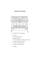
For the Vermont Castings
Defiant Encore Models:
#0028
#2140
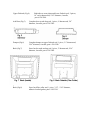
Defiant Encore Design Changes
The Defiant Encore damper was modified in October 1986 to provide a cast wedge
shaped stop to prevent the damper from striking or resting on the catalytic package when
operating the stove in the updraft mode. The torsion bar slide area in the centre of the
damper was widened to preclude torsion bar binding when opening and closing the
damper.
The ash drop assembly was modified in October 1986 to accept a split (two piece) half
hinge which allows 3 dimensional adjustment of the ash door resulting in an improved
ash door to ash drop and stove bottom seal.
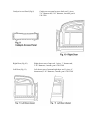
In November 1986 the ash door handle assembly was lengthened to accommodate the
plinth configuration and to increase the safety factor by avoiding the possibility of
scraping or burning the knuckles when opening or closing the ash door.
The secondary air valve (flap) was modified in December of 1986 to accept a pop rivet
which acts as a valve stop or limiter to prevent the valve from hanging below its intended
position and eliminate vibration of the air valve during catalytic burn periods.
The stove back and catalyst access plate was redesigned in December 1986 to allow ease
of servicing the catalyst block, reducing the risk of damaging the catalyst block and/or
the refractory access panel when performing maintenance.
A new ash door and ash pan bracket was introduced in January 1987 to provide better
operational tolerance and clearances and to accept heavier gasketing. A single ash door
hinge in and a new ash pan and cover were also provided at this time.
In February of 1987, the damper torsion bar was changed from cold rolled steel to
stainless steel to improve reliability of damper operation over wide ranges of temperature
change.
The thickness of the 3 damper tabs was doubled in March of 1987 to prevent the
possibility of bending during assembly and/or operation.
DEFIANT ENCORE
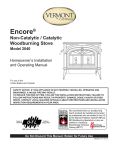
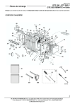
1. Exploded View Parts Illustrations
2. Parts List
3. Drill and Tap Illustrations
4. Drill and Tap Guide
5. Individual Part Replacement/Repair Procedures
6. Complete Disassembly Procedure
7. Complete Gasketing Procedure
8. Complete Assembly Procedure
9. Appendix
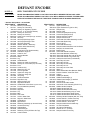
DEFIANT ENCORE
MODEL #:
0028 / 2140 DEFIANT ENCORE
FEATURES:
MODEL #0028 MANUFACTURED 7/11/86 THRU 4/25/90 WITH A GEISSER TESTING LAB. LABEL
MODEL #2140 MAUNFACTURED 5/17/90 THRU 11/5/91 WITH A WARNOCK HERSEY TESTING LABEL
CATALYST ACCESS IN THE BACK OF THE STOVE / DOUBLE PANE OF GLASS IN EACH DOOR
* denotes dead product - not available
ITEM # PART #
DESCRIPTION
1
130-7410* Bottom (no substitute)
2
130-7411 Primary Air Frame Only
500-0337 Primary Air Regulatory System
(Includes #2,3,4, 5, 17, & 120-3518 Gasket)
3
130-7412 Primary Air Valve Only
4
160-1493 Primary Air Rod Only
5
30001794 Socket Set Sc Cable Adjust (rep 120-0645)
6
130-7420 Ash Drop
7
130-7435 Ash Drop Split Hinge Upper
8
130-7436 Ash Drop Split Hinge Lower
9
130-7443 Ash Door (obsolete)
10
160-0622 Ashdoor Handle - Shaft Only
160-0663 Ashdoor Wood Handle Only
11
500-4024 Pawl Assembly
11a 120-3290 Large Jam Nut for Pawl Assembly
12
120-3004 Cash Door Hinge Pin
12a 120-3031 Cotter Pin #13
13
160-1039 Ash Pan Bracket
14
See Chart Ashlip
15
See Chart Leg
16
160-0600 Handle Bracket
17
500-5471 Primary Air Cable c/w 2 Sleeves
18
130-8609 Primary Air Cover Plate (rep 130-7418)
19
See Chart Front
20
See Chart Left Door Only
21
160-1396 Glass Clip Long .75"
22
130-7402 Door Hinge Plate
23
160-0416 Upper Door Hinge Pin
24
160-0417 Lower Door Hinge Pin
25
120-1985 Jump Ring
26
130-7403 Left Door Manifold
27
See Chart Right Door Only
28
160-1394 Glass Clip Short .62"
29
130-7404 Right Door Manifold
30
30001759 Handle Stub w/ Set Screw (repl 500-4225)
31
130-7424 Front Air Manifold (obsolete)
32
See Chart Left End
33
See Chart Right End
34
See Chart Top
35
See Chart Back
36
See Chart Flue Collar
37
130-7413 Left Air / Wear Plate
38
130-7414 Right Air / Wear Plate
39
160-8629 Left Deflector
40
160-8630 Right Deflector
41
500-4600 Refractory Assembly (w/ Access Panel)
42
160-2503 Access Panel Only
43
30001152 Catalyst Block
44
160-2506 Heat Exchanger
45
160-2507 Refractory Cover (SS Piece On Top)
46
130-7416 Lower Fireback
ITEM # PART #
47
130-7417
500-0335
48
130-7421
49
160-1488
50
160-1036
51
160-1035
52
160-1034
53
160-1033
54
500-5470
55
120-1864
56
120-1846
57
130-7415
58
500-4265
59
130-7423
60
130-7434
61
500-4224
160-0660
500-4264
120-1243
62
130-7442*
63
160-1489
64
160-1490
65
120-1986
66
160-1486
67
160-1492
68
140-1115
69
500-2789
120-3537
70
130-7419
71
130-0797
72
130-0809
000-4444
73
160-1025
74
160-1027
500-5746
75
500-4022
160-0658
160-0661
120-1900
120-1308
120-3210
76
000-4342
77
160-0620
78
160-0650
79
120-1294
80
160-0664
81
120-2471
82
120-2560
83
120-6115
84
120-1310
DESCRIPTION
Upper Fireback Only
Upper Fireback Ass'y (#47 to #51)
Damper Only
Damper Tabs
Torsion Bar (Damper Rod) Clip
Torsion Bar (Damper Rod)
Damper Actuator Linkage
Damper Actuator Rod
Thermostat Coil & Rod Assembly c/w #55
Thermostat Eyelet Only
Friction Spring
Thermostat Access Cup
Damper Handle Stub Nickel c/w Set Screw
Damper Link Access Panel
Bottom Grate
Thermostat Handle Complete
Thermostat Wooden Handle Only
Thermostat Handle Stub c/w Set Screw
Thermostat Handle Long Screw Only
Catalyst Access Panel (no substitute)
Secondary Air Probe
Secondary Air Flap
Secondary Air Shim Ring
Secondary Air Link
Secondary Air Cover Plate
Glass (1)
Glass Gasket With Wire (Between Glass)
Interam Gasket 9" Under the Glass
Andiron
Griddle (No Quads)
Griddle Quad Straight (1)
Griddle Quad Straight (1) with Bolt
Ash Pan Only
Ash Pan Cover With Handle
Ash Pan & Cover Assembly (#73 & # 74)
Griddle Handle Complete
Griddle Handle Stub Only
Griddle Handle Wood Knob Only
Griddle Handle Bushing Only (2 used)
Griddle Handle Wood Handle Screw
Griddle Handle Wood Handle Nut Only
Fallaway Handle Complete (#85, #77, #78)
Ceramic Handle - Ceramic Part Only
Ceramic Handle Chrome Nub Only
Ceramic Handle - Screw Only
Damper Handle Wood Handle Only
1/4" SS Flat Washer
3/8" Narrow Flat Washer
Kawool 3/4" x 7" (4 Used)
Damper Handle Screw Only
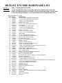
DEFIANT ENCORE HARDWARE LIST
MODEL #:
0028 / 2140 DEFIANT ENCORE
FEATURES:
MODEL #0028 MANUFACTURED 7/11/86 THRU 4/25/90 WITH A GEISSER TESTING LAB. LABEL
MODEL #2140 MAUNFACTURED 5/17/90 THRU 11/5/91 WITH A WARNOCK HERSEY TESTING LABEL
CATALYST ACCESS IN THE BACK OF THE STOVE / DOUBLE PANE OF GLASS IN EACH DOOR
* denotes dead product - not available
ITEM #
1
2
3
4
5
6
7
8
9
10
11
12
13
14
15
16
17
18
19
20
21
22
23
24
25
26
27
28
29
30
31
32
33
34
35
36
37
38
39
40
41
42
43
44
45
46
47
48
PART #
120-0900
120-0896
120-1374
120-1372
120-2474
120-0417
120-3210
120-3290
120-1338
120-0482
120-2488
120-1443
120-1745
160-0600
120-8610
120-0848
120-1347
120-3029
120-0991
120-2560
120-0334
120-1392
120-1376
120-1326
120-0881
120-2473
120-0907
120-3329
120-2471
120-0563
120-1243
120-2906
120-1986
120-0980
120-0993
120-1340
120-1310
120-1294
160-1396
160-1394
120-1378
120-6115
120-1846
120-2470
30001794
160-1488
120-1864
120-1985
DESCRIPTION
¼ -20 x ¾” Black Phillips Round Head Screw
¼ -20 x ⅝” Black Phillips Round Head Screw
¼ -20 X ¾” Hex Head Cap Screw
¼ -20 X ⅝” Hex Head Cap Screw
Washer, Zinc ¼” Flat
¼ -20 x ¼” Knl Cup Point Socket Set Screw
¼ -20 Hex Nut
⅜-16 Toplock Z Hex Head Jam Nut
¼ -20 x ½” Hex Head Cap Screw
¼ -20 x ½” Socket Flat Head Screw
Washer, Zinc ⅜” Flat
⅜ -16 x 1 ¼” Zinc Hex Head Bolt
¼ -20 x 1” Zinc Hex Head Leveler Bolt
Handle Holder
⅜ -16 x 1¼“ Socket Head Allen Bolt
¼ -20 x 2” Black Phillips Flat Head Screw
¼ -20 x ½” Hex Head Leveler Bolt
Pin, Cotter .080 x 1 9/16”
10-24 x ¾” Zinc Phillips Pan Head Screw
Washer, ⅜” Narrow
7/16-20 x 1” Socket Set Screw
¼ -20 x 2” Zinc Hex Head Cap Screw Gr 2
¼ -20 x 1” Hex Head Cap Screw
¼ -20 x 1” Black Hex Head Cap Screw Gr 2 (or sub 120-1376)
¼ -20 x ¾” Phillips Flat Head Screw
Washer, Black ¼” Narrow Flat
¼ -20 x 1” Black Phillips Round Head Screw
Nut, ¼ -20 Plain Square
Washer, ¼” Flat .294 id x .620 od Stainless Steel
5/16-16 x 5/16” Socket Set Screw
8-32 x 2” – Z Slot Round Head
Rivet, Pop ⅛ dia x ⅛ Grip {or use #6 x ¼” Round Head Screw}
Shim Ring, 18 Ga Nickel
10-24 x ¼” Phillips Pan Head Screw
¼ -20 x ⅜” Phillips Pan Head Screw
¼ -20 x ½” Stainless Steel Hex Head Cap Screw {replaced 120-1373 - 5/8” May 03}
¼ -20 x 3” Zinc Slotted Pan Head Screw
¼ -20 x 3⅜” Zinc Slotted Pan Head Screw
Glass Clip, Long .75”
Glass Clip, Short .62”
¼ -20 x 1¼” Hex Head Cap Screw
Kawool ¾” x 7”
Friction Spring
Washer, ¼ Plain Flat
¼ -20 x ⅜” Black Socket Head Cap Screw {replaces 120-0645}
Tab, Damper
Eyelet, Thermostat Wire
Jump Ring
Shell Parts - Defiant Encore Model #0028 / 2140
Part Name
Classic
(130)
Red
(131)
1304280 2324280*
Flue Collar
Ash Lip
1307406 2327406*
Leg
1307427 1317427
Front
1308612* 1318612*
Left Door
1308613*
N/A
Right Door
1308614*
N/A
Left End
N/A
N/A
Right End
1308619* 1318619*
Top
1307405 1317405
Back
1307439 1317439
*Substitute for original number
Sand
(132)
Blue
(133)
Midn't
(134)
Ant Grn
(138)
Ant Brn
(139)
Gray
(136)
1324280
1327406
1327427
1328612*
1328613*
1328614*
N/A
1328619*
1327405
1307439*
1334280
1337406
1337427
1338612*
1338613*
1338614*
N/A
1338619*
1337405
1337439
1344280
1347406
1347427
1348612*
1348613*
1348614*
N/A
1348619*
1347405
1307439*
N/A
N/A
N/A
N/A
N/A
N/A
N/A
N/A
N/A
N/A
N/A
N/A
N/A
N/A
N/A
N/A
N/A
N/A
N/A
N/A
N/A
N/A
N/A
N/A
N/A
N/A
N/A
N/A
N/A
N/A
PACKED INSIDE THE STOVE
500-7300
Parts Bag
500-4022 Griddle Handle Complete
160-0658 Griddle Handle Stub Only
160-0661 Griddle Handle Wooden Knob Only
120-1900 Griddle Bushing (2 Used)
120-1308 8-32 x 1" Phillips Pan Head Screw
120-3210 1/4-so Plain Hex Nut
160-0600 Holder, Door Fallaway Handle
120-5116 Allen Wrench, 1/8” Short Arm
120-5147 Allen Wrench, 5/32” Short Arm
120-2061 #10 x ¾” Black Phillips Pan Head Sheet Metal Screw
000-4342
Complete Handle Package
160-0660
Thermostat Wooden Knob
120-1243
Thermostat Screw 8-32 x 2"
2000913
Encore 0028/2140 Manual
GASKETS
120-3588
5/16” Medium Density 6ND Gasket
4’
Left Door
3'
Right Door
3.5’
Damper Housing for Damper
3'
Upper Fireback
1.4'
Lower Fireback
4’
Ashdrop
3.5'
Catalytic Access Panel
5'
Back
120-3668
5/16” Gasket Wire Fiberglass with Core
4’
Top for Griddle
120-3537
Interam Gasket 9" Long
1
Bottom of Each Glass
120-6115
Kaowool 3/4" x 7"
6
Lwr Fireback, Ref Package
120-3591
5/16” Adhesive Backed Gasket
3.25’
Flue Collar
120-3589
3/8" Low Density 6ND Fiberglass
3.5'
Ashdoor
120-3518
Pre-formed Gasket
1
Primary Air Frame
120-3556*
3/16" 4ND Black Fiberglass Gasket
3'
Each Glass Panel
*000-3427 kit contains enough gasket and cement to gasket all glass with rope gasket
ACCESSORIES
Heat Shields
160-1755 1 ¼” Spacer Used On Bottom & Rear
140-2252 Ashdoor Heatshield
000-5834 Spacer Hardware Kit – Set of 4-160-1755 120-1780 Ashdoor Heatshield Spacer
000-5925 Internal Rebuild Kit
Complete interior rebuild comes with lower fireback, upper fireback assembly, kawool,
refractory assembly,heat exchanger, cement, hardware, gaskets & instructions.
Warming Shelf
130-2221 Left Bracket
130-2222 Right Bracket
160-1705 Mittenrack
500-7234 Hardware Package
Part Name
Classic Old Red
Sand
Blue
Midnt
Ant Grn Ant Brn
Gray
Shelf
1302208 1312208 1322208 1332208 1342208
N/A
N/A
N/A
N/A
N/A
Dagon Bracket 1302220 1312220 1322220 1332220 1342220
N/A
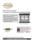
Defiant Encore Drill and Tap Guide
Key
Drill
Depth
Tap Size
Tap Type
A
B
C
D
E
F
G
H
I
J
K
L
M
N
O
P
Q
R
S
T
U
V
13 / 64"
# 22
# 22
# 22
25 / 64"
13 / 64"
13 / 64"
13 / 64"
13 / 64"
13 / 64"
13 / 64"
13 / 64"
3 / 16"
5 / 16"
3 / 16"
1 / 8"
5 / 16"
1 / 8"
"W"
"G"
3 / 8"
1 / 4"
Thru
1 / 2"
3 / 8"
Thru
Thru
1 / 2"
5 / 8"
3 / 8"
7 / 16"
11 / 16"
27 / 32"
3 / 4"
Thru
Thru
11 / 16"
1 / 2"
Thru
Thru
Thru
Thru
Thru
Thru
1 / 4" - 20
10 - 24
10 - 24
10 - 24
7 / 16" - 20
1 / 4 - 20
1 / 4 - 20
1 / 4 - 20
1 / 4 - 20
1 / 4 - 20
1 / 4 - 20
1 / 4 - 20
Taper
Bottoming
Bottoming
Taper
Taper
Bottoming
Bottoming
Bottoming
Bottoming
Bottoming
Bottoming
Bottoming
3 / 8 - 16
Taper
*Note :
When threading to the bottom of a blind hole, always finish with a
bottoming tap after cleaning the hole of all chips.
Defiant Encore – Individual Repair Section
GENERAL: The manner in which to proceed with the most repairs to this stove will be
obvious to the competent mechanic. Individual parts replacement and adjustment
procedures are covered in the Disassembly and Assembly sections of this manual.
Cleanings, re-gasketing and/or cementing procedures are covered in the Cementing and
Re-Gasketing sections of this manual. There are, however, certain techniques and
procedures outlined below and on the following pages which will save the mechanic both
time and effort.
CAUTION: When reassembling a part requiring gasketing or cementing, both the part
being replaced or reassembled and the entire mating surface to which it is attached must
be thoroughly cleaned to bare metal of old furnace and/or gasket cement before recementing or re-gasketing. If the cleaning process is not thorough, proper alignment and
a complete seal will be impossible to achieve.
Replacing the Primary Air Valve to Thermostat Cable
Tools Required
•
•
•
•
•
•
7/16” Combination wrench (box
& open end)
Phillips Screw Driver, # 2 tip
Needle Nose Pliers, 6”
Cold Chisel, ½”
Hammer, Ball Peen, 12 oz.
Drop Light or Flash Light
•
•
•
•
•
1/16” diameter Gas Welding
Rod, 36”
Caulking Gun, Frame Type
Allen Wrench, 1/8”
Thermocement, 11 oz. tube
Safety Goggles
STEP 1:
Remove the primary thermostat handle.
STEP 2:
Remove the thermostat access cup. It may be necessary to use the cold
chisel and hammer at the mating seam to loosen.
STEP 3:
Remove the thermostat, stainless steel washer and spring from the
thermostat pocket by pulling straight out.
STEP 4:
Remove the primary air frame and valve assembly. It may be necessary to
use the cold chisel and hammer at the mating seam to loosen. Pull the
frame away from the stove bottom and to the right gently, to protect the
primary air rod.
STEP 5:
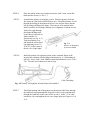
Remove the old cable from either the air valve or thermostat jump ring.
STEP 6:
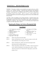
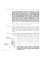
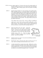
Fabricate a cable fishing tool from the 1/16” diameter X 36” gas welding
rod as shown in figure R-1. Make the 2” bend and the ¼” loop on the
opposite end of the rod on the same plane.
Fig. R-1:
STEP 7:
Cable fishing tool, 36” gas welding rod, 1/16” dia.
Remove the stove griddle and the first section of stove pipe above the flue
collar.
STEP 8:
Insert the cable fishing tool into the primary air frame opening from right
to left with the 2” bend at between 1 and 2 o’ clock. Force the fishing tool
by pushing and twisting it slightly around the inside of the primary air
tube and up between the right stove end and the right air/wear plate.
While pushing the fishing tool, look into the griddle opening and watch fir
the end of the fishing tool to pass the thermostat pocket. When the end of
the cable fishing tool becomes visible, stop moving the tool and reach
through the thermostat pocket with the needle nose pliers and pull about
2”- 4” of the fishing tool inside the firebox. If you do not succeed on the
first attempt, remove the fishing tool from the stove, straighten it,
maintaining the 2”, 150 degree bend and try again.
STEP 9:
Slip the looped end of the new primary thermostat cable over the looped
end of the fishing tool and close the loop with your pliers. Reach inside
the stove and pull the fishing tool until the new cable comes through the
thermostat pocket.
STEP 10:
Clean the primary air frame, thermostat access cup and their mating
surface of all old furnace cement. Apply new furnace cement to the
thermostat access cup and the primary air frame and proceed to steps 20
thru 22 of the assembly section of the manual.
Replacing or Servicing the Damper Linkage
Tools Required
•
•
•
Allen Wrench, 5/32”
Caulking Gun Frame
Thermocement, 11 oz. tube
STEP 1:
•
•
•
Cold Chisel, ½”
Hammer, Ball Peen, 12 oz.
Safety Goggles
Place the damper in the open or updraft position and remove the damper
handle stub.
STEP 2:
Remove the damper link access panel. Use the cold chisel in the lower
cement seam to loosen.
STEP 3:
Reach inside the damper linkage opening and while holding the damper
actuator link with one hand, pull the damper handle rod from its drilling in
the left stove end and the forward drilling in the actuator link with the
other hand. Do not drop the 3/8” flat washer between the stove end and
the air/wear plate.
STEP 4:
With the actuator link, rotate the damper towards the closed position and
disengage the actuator link from the damper torsion bar.
STEP 5:
Service and/or replace the damper handle rod, actuator link and the 3/8”
flat washer.
STEP 6:
Clean the cement groove of the damper linkage access panel and its
mating surface on the left air/wear plate and upper fireback of all old
furnace cement. Proceed to step 26 thru 28 of the assembly section of this
manual.
Replacing or Servicing the Upper Fireback and Damper Assembly
(Also see note in Appendix)
Tools Required
•
•
•
•
Ratchet Handle, 3/8” drive
7/16” Deepwell socket, 3/8”
drive
Rolling head pry bar, 6”- 10”
Allen Wrench, 5/32”
•
•
•
•
•
Caulking Gun Frame
Thermocement, 11 oz. tube
Cold Chisel, ½”
Hammer, Ball Peen, 12 oz.
Safety Goggles
Perform steps 1 thru 5 of the damper linkage repair section.
STEP 1:
Remove the 4 cap screws that secure the upper fireback to the right and
left air/wear plates.
STEP 2:
Place the chisel end of the rolling head pry bar in the seam between the
upper and lower fireback about 2” in from the right or left air/wear plate.
Tap the chisel end of the pry bar with the ball peen hammer until fireback
starts to separate from the lower fireback. Pull down on the pry bar until
the cement holding the upper fireback to the stoves top loosens. Remove
the upper fireback and damper assembly.
STEP 3:
Service and/or replace the upper fireback, damper, torsion bar, damper
tabs, and torsion bar clips.
STEP 4:
Re-gasket the damper and the upper fireback. Refer to the gasketing
section of this manual.
STEP 5:
Clean the upper fireback of all old furnace cement. Clean the cement
channel for the upper fireback in the underside of the stove top
thoroughly, paying particular attention to the right and left corners.
STEP 6:
Cement the upper fireback channel in the underside of the stove top and
proceed to steps 24 thru 28 of the assembly section of this manual.
Replacing or Servicing Damper Tabs and Torsion Bar Clip
Tools Required
•
•
Ratchet Handle, ¼” drive
• 2” Extension, ¼” drive
7/16” Socket, ¼” drive
• Screwdriver, Phillips, # 2 tip
• 7/16” Combination Wrench (box and open)
STEP 1:
Remove the flue collar.
STEP 2:
Replace and/or service the damper tabs and torsion bar clip. Reassemble
and check damper operation for a good damper seal and ease of
movement.
STEP 3:
Replace the flue collar.
If the flue collar gasket is dried out and/or
compressed to the point where metal to metal contact is noted between the
flue collar and the stove back, replace the flue collar gasket. Refer to the
gasketing section of this manual for instructions.
Replacing or Servicing the Refractory Assembly
Tools Required
•
•
•
•
•
7/16” Combination Wrench (box
& open)
Cold Chisel, ½”
Hammer, Ball Peen, 12 oz.
Caulking Gun Frame
Safety Goggles
STEP 1:
STEP 2:
STEP 3:
STEP 4:
STEP 5:
•
•
•
•
Thermocement, 11 oz. tube
Masking Tape
Tape Measure, 6”
Shears, 10”- 12”
Remove the 6 screws that fasten the stove back to the right and left stove
ends.
Tap the cold chisel into the seam where the bottom flange of the stove
back joins the stove bottom to break the cement seal.
Lift the stove back up out of its cement groove in the stove bottom and
pull the back from the stove, bottom first.
Replace and/or replace service the refractory package, catalyst block, heat
exchanger, heat deflectors and refractory cover. Clean the catalyst block
and refractory package with low pressure air.
Reassemble the refractory assembly. Tape the heat exchanger, catalyst
block access panel and refractory cover in place with masking tape.
STEP 6:
Inspect the kaowool strips in the lower fireback and the bottom of the
stove back. If the kaowool strips are compressed below the top edge of
the inside ribs of either the lower fireback or the stove back, replace them.
The kaowool strips when in place must provide a complete seal as well as
a cushion for the refractory package.
STEP 7:
Clean all old furnace cement from the bottom flange of the stove back and
the stove back and the stove back cement channel in the stove bottom.
STEP 8:
Re-gasket the stove back. Refer to the gasketing section of this manual for
instructions. Fill the stove back cement channel in the stove bottom with
thermocement.
STEP 9:
Place the refractory package into the stove back. Place the right and left
heat deflectors into their proper positions in the stove back.
STEP 10:
Install the stove back.
Replacing the Secondary Air Thermostat, Flap and Linkage
Tools Required
Screwdriver, Phillips, # 2 tip.
Refer to step 30 of the disassembly section of this manual and steps 31 and 32 of the
assembly section of this manual.
Eliminating Air Leaks at the Ash Door
Tools Required
•
•
•
•
7/16” Combination Wrench (box
& open)
Ratchet Handle, 3/8” drive
Extension, 3”, 3/8” drive
7/16” Socket, 3/8” drive
•
•
•
•
9/16” Socket, 3/8” drive
1/8” Allen Wrench
Rubber Mallet, 4 lbs. dead blow
Wire Brush
Refer to steps 33 thru 35 of the assembly section of this manual.
Eliminating Air Leaks at the Fire Door
Tools required
•
•
•
7/16” Combination Wrench (box
• Wire Brush
& open)
• Rubber Mallet, 4 lbs. dead blow
9/16” Combination Wrench (box
• 7/32” Allen Wrench
& open)
Flat file, medium cut
• Gasket Cement, 3 oz. tube
Refer to step 41 of the assembly section of this manual. If a good door seal cannot be
achieved, remove the doors and re-gasket them following the instructions in the gasketing
section of this manual. If the right fire door seals and the left does not, remove the left
door. Strip the old gasket from its groove and clean the groove thoroughly with the wire
brush. Apply an unbroken bead of gasket cement in the bottom of the groove. Cut a 4”
length of 1/8” thermocord gasket and place it in the bottom of the groove. Press the
gasket into the groove evenly and trim off the excess. Apply an unbroken bead of gasket
cement onto the 1/8” thermocord gasket and the sides of the gasket groove. Cut a 4”
length of 5/16” thermocord gasket and place it in the groove evenly all the way around
and trim off the excess. Install the left door and proceed with the door adjustment
outlined in step 41 of the assembly section of this manual.
Defiant Encore – Complete Disassembly
Tools Required
•
•
•
•
•
•
•
•
•
•
•
•
•
•
•
•
•
•
1-Drop cloth, 8”x 8” (minimum size)
1-Pair of safety goggles
1-Respirator, dust & mist
1-Wire brush 1½” x 6”, 13” overall
1-7/16” Combination wrench (box &
open end)
1-9/16” Combination wrench (box &
open end)
3/8” Drive ratchet handle
1-Wrench, socket, 7/16”, deepwell,
3/8” drive
1-Wrench, socket, 9/16”, deepwell,
3/8” drive
1-Common flat blade screwdriver, 6”
long
1-Common flat blade screwdriver, 8”
long
1-Phillips screwdriver # 2 tip, 6”
long
1-Phillips screwdriver # 3 tip, 8”
long
1-Hex key (Allen) wrench, 1/8”
1-Hex key (Allen) wrench, 5/32”
1-Hex key (Allen) wrench, 3/16”
1-Hex key (Allen) wrench, 7/32”
1-Drop light A.C. 40-60 watt, 15”25” cord
•
•
•
•
•
•
•
•
•
•
•
•
•
•
•
•
•
•
•
•
•
•
1-Pail electricians’ side cutting
pliers, 6”
1-Putty knife
1-Shop type vacuum cleaner with
attachments
1-Ball peen hammer, 12 oz. or 16 oz.
1-Hammer, brass face, 12 oz. or 16
oz
1-Rubber mallet, 4 lbs. dead blow
1-Cold chisel, ½”
1-Cold chisel, 3/8”
1-Cold chisel, 5/8”
1-Punch/Drive pin, 1/8”
1-Punch/Drive pin, ¼”
1-Punch/Drive pin, 3/8”
1-Caulking gun frame
1-Rolling head pry bar, ½”x 15”
1-Pinch bar, ½” x 15”
1-Water pail, 2 gallon or larger
1-Sponger or water absorbent cloth
1-Tape measure, 6”
1-Machinists rule, 6”
1-Pair cutting shears, 6”- 8”
Kitchen knife, serrated, 6”- 7” blade
Clean rags
Disassembly
STEP 1:
Lift out the griddle. Remove the ash pan and dump ashes in a safe
container outdoors. Wash the ash pan and dry it. The ash pan will make a
good container for screws, bolts, nuts, washers and small hardware items
during the disassembly of the stove.
STEP 2:
Remove the right and left door assemblies. Raise the door until the lower
hinge pin clears its drilling, angle the door bottom slightly outward and
pull down, releasing the upper hinge pin from its drilling.
STEP 3:
Remove the damper handle stub with the 5/32” Allen wrench.
STEP 4:
Remove the thermostat handle with the 1/8” Allen wrench.
STEP 5:
Remove the flue collar, 2 each, Phillips round head machine screws, ¼20x1”.
STEP 6:
Remove the top, 2 each, ¼-20 x ¾” hex head cap screws and 4 each, ¼”
flat washers, right and left inside rear and 1 each, ¼-20 x 3/4” Phillips flat
head machine screw, centre front under the griddle handle indent. Strike
the top upward with the rubber mallet to loosen the cement and remove.
STEP 7:
Remove the primary air thermostat access cup, 2 each, ¼-20x1/2” hex
head cap screws. Use the cold chisel in the cement seam.
STEP 8:
Remove the damper link access panel, 2 each, ¼-20x1/2” socket flat head
machine screws. Use the cold chisel in the cement seams and a ball peen
hammer to loosen.
STEP 9:
Remove the damper handle rod from its drilling in the left stove end and
the forward drilling in the damper actuator link to fall between the left
stove end and the left air/wear plate.
STEP 10:
Remove the upper fireback and damper assembly, 4 each, ¼-20 x 1” hex
head cap screws and 4 each, ¼” flat washers. Do not allow the damper
actuator link to fall into the opening between the wear plate and the stove
end.
STEP 11:
Remove the lower fireback, 2 each, ¼-20 x 1” hex head cap screws and 2
each, ¼” flat washers. Pry the fireback loose with a pinch bar from its
bottom cement channel.
STEP 12:
Remove the stove back, 6 each, ¼-20 x 3/4” hex head cap screws and 6,
each ¼” flat washers. Strike the stove back joint areas with a rubber
mallet to loosen the cement.
STEP 13:
Remove the combustion package assembly and the right and left heat
deflectors from the stove back. Handle the combustion package assembly
gently and place it in a safe area until you are ready to examine and clean
it.
STEP 14:
Disconnect the thermostat cable at the primary air valve (outer rear of the
stove bottom). Loosen the Allen set screw and snip off the cable loop.
Gently pull the thermostat from its recess in the right air wear plate. Do
not lose the washer, spring, jump ring and cable in the process.
STEP 15:
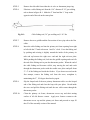
Remove the right air/wear plate, 2 each, ¼-20 x 1” hex head cap screws.
Chip away the cement at the joints and mating surfaces with a cold chisel
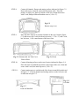
and ball peen hammer. Drive a ½” cold chisel between the rear flange
(extreme top and bottom) of the wear plate and the stove end and gently
pry loose (see fig. D-1).
Fig.D-1: Separating Air/Wear Plate from Stove End.
STEP 16:
Remove the left air wear plate, 2 each, ¼-20x1” hex head cap screws.
Chip away the cement at the joints and mating surfaces with a cold chisel
and ball peen hammer. Drive the ½” cold chisel between the rear flange
(extreme top and bottom) of the wear plate and the stove end and gently
pry loose (see fig. D-1).
STEP 17:
Remove the stove front, 1 each, ¼-20 x ¾” hex head cap screw and 1
each ¼” flat washer holding the front to the left end. 1 each, ¼-20 x ¾”
hex head cap screw and 1 each, ¼” flat washer holding the front to the
right end, 1 each, ¼-20 x 1” hex head cap screw and 1 each, ¼-20 hex nut
holding the front to the bottom. Strike the air manifold with a rubber
mallet sharply at the right and left joints and remove the front with the air
manifold and andirons attached.
STEP 18:
Remove the right end, 1 each, ¼-20 x ¾” hex head cap screw and 1 each,
¼” flat washer located at the centre of the inside bottom flange. Rock the
end loose and remove.
STEP 19:
Remove the left end, 1 each, ¼-20 ¾” hex head cap screw and 1 each, ¼”
flat washer locate at the centre of the inside bottom flange. Rock the end
loose and remove.
STEP 20:
Remove the primary air tube cover plate, 3 each, ¼-20x2” Phillips flat
head machine screws.
To loosen the screws, place a # 3 Phillips
screwdriver top into the screw and strike the screwdriver handle sharply
with a ball peen hammer. Chip the furnace cement loose from the seams
and gently pry the cover plate loose.
STEP 21:
Remove the primary air regulator system, 2 each, ¼-20 x 5/8” Phillips
round head machine screws. Tap the air frame gently at the seams and
remove.
STEP 22:
Remove the ash drop assembly. Remove the hairpin cotter from the upper
end of the ash door clevis pin.
Pull the ash door clevis pin down,
disengaging the hinge. Remove the ash door assembly. Remove the flat
ash grate. Turn the stove bottom over and remover, 4 each, ¼-20 x ¾”
hex head cap screws and 4 each, ¼” flat washers holding the ash drop to
the stove bottom. Gently tap and pry the ash drop loose.
STEP 23:
Remove the ash lip, 2 each, ¼-20 x ½” socket flat head machine screws.
Remover the 4 stove legs and handle holder, 4 each, 3/8”-16 x 1¼” hex
head bolts and 4 each, 3/8” flat washers.
STEP 24:
Remove the primary air manifold from the stove front, 1 each, ¼-20 x 2”
hex head cap screw at the centre of the manifold. Chip cement at the
joints with a cold chisel and ball peen hammer. Pry the manifold loose
with a pinch bar. Remove the andirons, 1 each, ¼-20 x ½” hex head cap
screw and 1 each, ¼” flat washer per andiron.
STEP 25:
Remove the two piece half hinge from the ash drop, 3 each, ¼-20 x ¾”
hex head cap screws and 3 each, ¼” flat washers. Take the split half hinge
apart, 2 each, ¼-20 x ¾” hex head cap screws and 2 each, ¼” flat washers.
STEP 26:
Remove the ash pan bracket from the ash door, 2 each, ¼-20 x ½” hex
head cap screws and 2 each, ¼” flat washers. Remove the handle from the
ash door, 1 each, 3/8”-16 hex toplock jam nut on the pawl. Loosen the ¼20x ¼” socket set screws on the pawl. Remove the pawl and pull the
handle out.
STEP 27:
Remove the damper from the upper fireback, 3 each, ¼-20 x ½” hex head
cap screws and 3 each, flat damper tabs. Lift out the damper. Remove the
torsion bar, 1 each, ¼-20 x ½” hex head cap screws and 1 each, torsion bar
clip. Pull the torsion bar from the upper fireback.
STEP 28:
Remove the primary air valve from the primary air frame. Pry the air rod
clip from the end of the rod. Push the air rod through its drillings and
remove the valve and rod from the frame.
STEP 29:
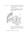
Examine the combustion package assembly. Check the heat exchanger for
distortion, loose spot welds, etc. Check the right and left heat deflectors
for distortion. Check the refractory stainless steel cover for distortion.
Replace any defective parts.
Check the catalyst block for general
deterioration. Check the refractory chamber and the catalyst block access
panel for breaks, chips, separations, etc. If the catalyst block, refractory
chamber and refractory access panel are in good condition, clean them
with low pressure air from your vacuum cleaner.
STEP 30:
Remove the catalyst access plate from the stove back, 4 each, ¼-20 x 5/8”
Phillips round head machine screws. Remove the secondary air cover
plate from the stove back, 2 each, ¼-20 x 3/8” Phillips pan head machine
screws. Remove the secondary air flap, 1 each, 10-24 x ¼” Phillips pan
head machine screw and 1 each, shim ring. Remove the secondary air link
from the air flap. Remove the secondary air probe, 1 each, 10-24 x ¼”
Phillips pan head machine screw. Separate the air link from the secondary
air probe. Check the air flap and air link for distortion. Check the air flap
and air link for distortion. Check the air probe coil for breaks and/or heat
damage. Replace any suspect parts.
STEP 31:
Examine all castings for cracks, chips, distortions, etc. Remove all old
gasket material from the gasket channels and mating surfaces. Remove all
gasket and furnace cement from channels and mating surfaces using the
appropriate size punch/drive pin in the channels and cold chisels on the
flanges and flat mating surfaces. Clean all channels and mating surfaces
with a wire brush (hand or power).
STEP 32:
Examine all mechanical linkage parts for distortion, worn or egg shaped
drillings, unusual wear, burrs, etc.
Replace any bent tabs or clips.
Repair or replace as necessary.
STEP 33:
Place the doors with their outside faces down on a clean flat surface.
Remove the door manifold, 2 each, ½” x ¾” glass clip. Remove 3 each,
10-24 x ¼” Phillips pan head machine screws and 3 each, glass clips.
Reach underneath the door and push the glass and gaskets upward and out
of the frame. Scrape the frame with a putty knife, removing all dry
cement and old gasket material. Inspect and clean the glass. Replace any
broken or cracked glass. Check the condition of the formed gasket which
separates the glass panes. Replace it if it is broken, crushed or badly
deformed. Remove the hinge boss from the door frame, 3 each, ¼-20 x
½” hex head leveler bolts and 3 each, ¼” flat washers. Inspect the hinge
pins. If the pins are broken or severely bent, drive them out of the hinge
boss with a 1/8” punch/drive pin and ball peen hammer. Remove the
gasketing from around the door frame.
Clean the gasket channels.
Unscrew the door handle and tab assembly. Inspect the 7/16”-20 x ¾”
socket set screw for looseness in the door and/or damaged threads. If
defective, remove with a 7/32” Allen wrench. After thorough cleaning,
pain the outside surface of the doors and hinge bosses at this time. Use
Vermont Castings High Temperature Aerosol Stove Paint (black), part
number 000-0031 and follow directions on the can.
Gasketing
STEP 1:
Remove the old gasketing paying particular attention to the place where a
continuous gasket meets itself.
STEP 2:
Clean all gasket channels and grooves with a wire brush (hand or power).
Remove any stubborn deposits of gasket cement with the appropriate size
punch/drive pin or cold chisel.
STEP 3:
Clean all parts to be gasketed with you shop vacuum. Place clean parts on
a clean level surface
STEP 4:
Select the appropriate type and size of gasket. Cut to the recommended
length allowing you an inch or two excess.
STEP 5:
Using the 3 oz. tube of gasket cement (part # 120-6122), place an
unbroken 1/8” bead of gasket cement in the channel or groove to be
gasketed.
STEP 6:
Starting with one end, press the gasket into the cemented channel or
groove. If the gasket meets itself, insure that you have a good joint before
trimming excess gasket with shears or side cutters. Do not overlap gasket
ends or leave ragged edges.
*NOTE: Gasketing is indicated by the cross hatch symbol in the illustrations.
STEP 7:
If possible, place the gasketed part firmly against its normal mating
surface in order to seat the gasket evenly in its cemented channel or
groove. Use a 1 x 4, 18” long, wooden straight edge where required.
Remove gasketed part and clean any excess gasket cement that has
squeezed out around the gasket before placing aside to dry.
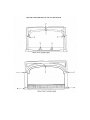
Defiant Encore Gasket Requirements. Refer to the Gasket Illustration figure numbers.
Top (Fig.1)
Griddle opening, one place, 4”-Armaseal 5/16” diameter, cored, part #
120-3668.
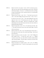
Ash Drop (Fig.2)
Ash drop to bottom seal, one piece, both sides and back. 4’
Thermocord 5/16” diameter, 6 needle, part # 120-3588.
Lower Fireback (Fig.3)
Both sides to wear plates seal, two pieces, 8” each,
thermocord, 5/16” diameter, 6 needle, part # 120-3588.
Upper Fireback (Fig.4)
Both sides to wear plates and lower fireback seal, 2 pieces,
18” each, thermocord, 5/16” diameter, 6 needle,
part # 120-3588.
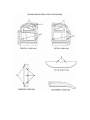
Ash Door (Fig.5)
Complete door to ash drop seal, 1 piece, 4’ thermocord, 3/8”
diameter, 4 needle, part # 120-3589.
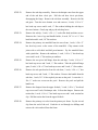
Damper (Fig.6)
Complete damper to upper fireback seal, 1 piece, 3.5’ thermocord,
5/16” diameter, 6 needle, part # 120-3588.
Back (Fig.7)
Stove back to ends and top seal, 1 piece, 5’ thermocord, 5/16”
diameter, 6 needle, part # 120-3588.
Back (Fig.8)
Stove back flue collar seal, 1 piece, 3.25’, 5/16” diameter,
adhesive backed gasket, part # 120-3591.
Catalyst Access Panel (Fig.9)
Catalyst access panel to stove back seal, 1 piece,
3’6”, thermocord, 5/16” diameter, 6 needle, part #
120-3588.
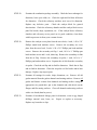
Right Door (Fig.10)
Right door to stove front seal, 1 piece, 3’, thermocord,
5/16” diameter, 6 needle, part # 120-3588.
Left Door (Fig.11)
Left door to stove front and right door seal, 1 piece, 4’,
thermocord, 5/16” diameter, 6 needle, part # 120-3588.
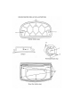
Door Glass (Fig.12)
Gasket #1 provides cushioning between the casting and the
bottom of the glass panes, 1 piece, 9”, Interam 3M, flat,
part # 120-3537. This gasket is applied with Tite Bond
Glue or gasket adhesive.
Gasket #2 provides cushioning between the outer glass
pane and the castings in addition to a seal, 1 piece, 3’, 2”
thermocord, 3/16” diameter, part # 120-3556 (part of
Gasket Kit 000-3427)
G
a
s
k
e
t
#
3
p
r
o
v
i
d
e
s
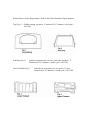
Gasket #3 provides cushioning and separates the inner and
outer glass panes. This gasket is pre-formed and comes
ready-made, part # 500-2798. This gasket does not require
glue or cement.
NOTE – Both doors require the same door glass gasketing.
Defiant Encore 0028/2140 Assembly Service Manual
General:
All parts were carefully inspected and cleaned to bare metal or replaced
during the disassembly process. Assembly may now begin. To achieve a
properly functioning, air tight stove, 6 each, 11 oz. tubes of thermocement,
part number 120-6125 are required. Cut the thermocement tube tips so
that a ¼”- 3/8” unbroken bead of thermocement may be applied to the
cement channels, flanges and/or flat mating surfaces.
*NOTE:
Cement is indicated by the shaded area in the “C” series illustrations.
**Caution
Pay strict attention to the type, size and number of fasteners called for in
the exploded view drawings, parts list and text.
STEP 1:
Place the stove bottom upside down on a flat surface. Install 4 each, hex
head leveler bolts (¼” -20x1”) in the 4 stove legs, finger tight. Install the
4 legs on the stove bottom using 4 each hex head bolts (3/8”-16x1-¼”) and
4 each, standard flat washers (3/8”). Place the stove handle holder
between the flat washer and the bolt head on the left front leg (right front
leg when the bottom is turned over to its normal position).
STEP 2:
Assemble the two piece half hinge using 2 each, hex head cap screws (¼20 ¾”) and 2 each, standard flat washers (¼”) finger tight. Install the two
piece half hinge on the ash drop, clevis facing the door opening with 3
each, hex head cap screws (¼-20x ¾”) and 3 each, standard flat washers
(¼”) finger tight.
STEP 3:
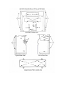
Cement the stove bottom at points indicated in Figure C-1. Place the ash
drop on the stove bottom and secure with 4 hex head cap screws (¼-20 x
¾”) and 4 each, standard flat washers (¼”).
Fig. C-1
Bottom (bottom view)
STEP 4:
Place the ash lip on the stove bottom and secure with 2 each, socket flat
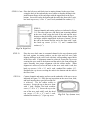
head machine screws (¼-20x ½”).
STEP 5:
Assemble the primary air regulator system. Place the primary air frame
face down on a flat surface (drilled bosses up). Thread the primary air rod
through the drilling in the bottom of the air valve and just start it into the
left top (hinge) drilling of the frame. Place the air valve and rod in the
frame so that the air rod hinge drillings are in alignment. Push the air rod
from left to right through
the aligned drillings and
secure the air rod in the air
frame with the 1/8”
friction clip (see Fig. A-1).
Turn the assembly over
and install the socket head
Fig. A-1
cap (adjusting) screw (¼Primary Air Regulatory
20 x 3/8”) in the centre of
System Assembled
the air valve, finger tight.
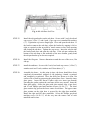
STEP 6:
Install the primary air regulator system on the cemented flange of the
inverted stove bottom with the hinged side down Fig. A-2 (protruding air
rod left). Secure with 2 each, Phillips round head machine screws (¼-20 x
5/8). Turn the stove bottom over onto its legs.
Cable Threading
Fig. A-2 Primary Air Regulator System Ready to be Installed
STEP 7:
Thread the running end of the primary air thermostat cable down through
the small hole and up through the large hole in the air valve and thread it
through the small hole in the centre of the air valve. Pull 6”-8” of cable
outside the valve and tighten the set screw finger tight (see Figures A-1 &
A-2).
STEP 8:
Cement all channels, flanges and mating surfaces indicated in Figure C-2.
Do not allow any cement to contact the thermostat cable. Place the
primary air tube cover plate in position on the stove bottom and secure
with 3 each, Phillips flat head machine screws (¼-20 x 2”).
Fig. C-2
Bottom (top view)
STEP 9:
Place the stove front in its cemented channel on the stove bottom (Figure
C-3) and secure with 1 each, hex head cap screw ( ¼”-20 x 1”) and 1 each,
hex lock nut ( ¼-20) centre bottom of the stove front.
Fig. C-3 Bottom with Air Tube Cover
Plate in Place
Fig. C-4 Front
STEP 10:
Cement all mating surfaces on the stove front as indicated in Figure C-4.
Place the front air manifold in position on the inside of the stove front and
secure with 1 each, hex head cap screw (¼-20 x 2”).
STEP 11:
Cement mating grooves on both ends of the front air manifold as indicated
in Figure C-7. Cement channels and mating surfaces on the left stove end
as indicated in Figure C-5.
Fig. C-5
Left End
Fig. C-7
Front Air Manifold
STEP 11 Cont.: Place the left stove end firmly into its mating channel in the stove front,
swing the back of the end onto the stove bottom so that the drilling in the
inside bottom flange of the end aligns with the tapped hole in the stove
bottom. Secure the end to the bottom and the end to the front with 2 each,
hex head cap screws (¼-20 x ¾”) and 2 each, standard flat washers (¼”).
STEP 12:
Cement channels and mating surfaces as indicated in Figure
C-6. Place the right stove end firmly into its mating channel
in the stove front, swing the back of the end onto the stove
bottom so that the drilling in the inside bottom flange of the
end aligns with the tapped hole in the stove bottom. Secure
the end to the bottom and the end to the front with 2 each,
hex head cap screws (¼-20 x ¾”) and 2 standard flat
washers (¼”).
Fig. C-6 Right End
STEP 13:
Place the stove back onto its cemented channel in the stove bottom, push
the back against its mating surfaces on the right and left stove ends
aligning drillings in the stove back with their corresponding tapped holes
in the stove ends. If alignment cannot be achieved, loosen the cap screws
securing the stove ends to the bottom and the ends to the front and tap the
entire assembly into proper alignment with the rubber mallet. When
alignment is achieved, secure the back to the stove ends with 6 each, hex
head cap screws (¼-20 x ¾”) and 6 each, standard flat washers (¼”).
Retighten the cap screws securing the ends to the bottom and the ends to
the stove front.
STEP 14:
Cement channels and mating surfaces on the underside of the stove top as
indicated in Figure C-8. Place the top in position on the stove front, ends,
and back insuring that a good all around seal
is achieved. Use the rubber mallet as
necessary. Secure the top to the stove front
with 1 each, Phillips flat head machine
screw (¼”-20 x ¾”). Secure the top to the
rear of the stove ends with 2 each, hex head
cap screws (¼”-20 x ¾”) and 4 each,
Fig. C-8 Top (bottom view)
standard flat washers (¼”) 2 per cap screw.
STEP 15:
Cement the mating surfaces on the reverse side of the left
air/wear plate as indicated in Figure C-9. Insert the front mating
surface of the left air/wear plate against the left end of the front
air manifold and the front of the left stove end at a 30 degree
angle. Holding the wear plate as close to the stove top as
possible, swing the back of the wear plate against its mating
surface (back of the left stove end). Tap into proper position with
the rubber mallet so that the top and bottom drillings in the wear
plate align with the tapped holes in the stove end. Secure with 2
each, hex head cap screws (¼-20 x 1”).
Fig. C-9 Left Air/Wear Plate
Fig. C-10 Right Air/
Wear Plate
STEP 16:
Cement the mating surfaces on the reverse side
of the right air/wear plate as indicated in Figure
C-10. Place the right air/wear plate inside the
stove in an upright position. Thread the primary
air system cable through the hole in the centre of
the thermostat pocket of the wear plate (see
Figure A-3). Insert the front mating surface of
the right air/wear plate against the right stove
end at a 30 degree angle. Holding the wear plate
as close to the stove top as possible, swing the
back of the wear plate against its mating surface
(back of the right stove end). Tap into proper
position with the rubber mallet so that the top
and bottom drillings in the wear plate align with
the tapped holes in the right stove end. Secure
Fig. A-3 Right Air/Wear Plate
with 2 each, hex head cap screws (¼-20x1”).
Ready to be Installed
STEP 17:
Insert the right and left heat deflectors in the right and left
bottom corners of the stove back. Cut 4 each, 5” strips of
¾” square kaowool. Place 2 each kaowool strips side by
side between the left and right pair of ribs in the bottom of
the stove back (see Fig.A-4).
Fig. A-4 Kaowool & Heat Deflector Placement
STEP 18:
Assemble the combustion package assembly. If the refractory package
and/or the catalyst access panel (refractory) are being replaced, it may be
necessary to cut and fit the access panel. Use the serrated edge kitchen
knife and achieve a good tight all around fit. Place the heat exchanger into
the front opening of the refractory assembly--tape in place with masking
tape. Insert the canned catalyst block into its opening in the rear of the
refractory package (honeycombs vertical). Insure that the catalyst block
slides over the lip of the heat exchanger and seats properly in its recess.
Place the catalyst access panel (refractory) against the catalyst block and
push in gently so that the access panel is flush with the edges of the
refractory assembly--tape in place with masking tape. Place the stainless
steel refractory cover on top of the combustion package assembly so that
the cover edges are even with the front and back edges of the refractory
assembly. Tape the cover in place with masking tape.
STEP 19:
Place the combustion package assembly into the stove back between the
vertical ribs on the inside of the stove back. Make sure that the kaowool
in the bottom of the stove back provides a good seal between the bottom
of the stove back and the combustion package assembly, effectively
isolating the secondary air passage from the right and left exhaust
passages.
STEP 20:
Assemble the thermostat and cable. Open the jump ring and hook the loop
on the end of the thermostat cable and the loop on the end of the
thermostat actuator rod onto the jump ring. Squeeze the jump ring
completely closed with pliers. Holding the thermostat
assembly so that the limiter bar is on top of the rod, swing the
cable actuator rod over the top of the thermostat shaft as
shown in Figure A-5. Place the friction spring on the
thermostat shaft and slide the spring up to the shaft stops.
Holding the thermostat assembly in the left hand and insuring
that the limiter bar is on top of the shaft and parallel with the
stove top, insert the end of the shaft, cable and actuator rod
through the hole in the centre of the thermostat pocket of the
right air/wear plate. Loosen the set screw on the primary air
valve and gently pull the slack out of the cable while
maintaining your grip on the thermostat shaft protruding out
of the right stove end.
Fig. A-5 Assembled Thermostat
STEP 20 Cont: When the slack is out of the cable, tighten the set screw on the air valve.
Push the thermostat shaft from inside the stove until stiff
resistance is felt from the friction spring, slip the thermostat
Fig. C-11
handle stub on the end of the shaft and push the handle stub
Thermostat
tight against the outside of the right stove end. Tighten the
Access Cup
set screw in the handle stub against the flat side of the shaft.
Cement the mating surface of the thermostat access cup (Fig. C-11).
Place the ¼” stainless steel flat washer on the thermostat shaft and slide it
against the limiter bar. Insert the thermostat access cup over the
thermostat shaft; rotate the access cup to its proper position, aligning the
drillings in the access cup with the tapped holes in the right air/wear plate.
Secure with 2 each, hex head cap screws (¼-20 x ½”).
STEP 21:
Adjust the primary air system. Loosen the set screw on the primary air
valve. Holding the cable in one hand, move the thermostat handle through
its full range of movement insuring that all the slack is out of the cable and
that the cable is responding to the movement of the thermostat handle
without catching or binding. With the thermostat handle in the closed
position (towards the rear of the stove) and the cable set screw loose, the
primary air valve will fall freely to the closed position. Gently pull the
cable until the primary air vale just begins to open. Pull the air valve
closed by pulling the set screw in the centre of the air valve until the valve
seats in the air frame. Tighten the set screw. Move the thermostat handle
to the full open position (towards the front of the stove). Check the air
valve to be sure it is in the open position.
STEP 22:
Sleeve and cut the excess from the primary air system cable. Thread the
copper sleeve over the end of the cable. Loop the free end of the cable
back through the copper sleeve and pull the sleeve and loop up within 1”
of the air valve set screw as shown in Fig.A-6. Insure that the sleeve and
the cable loop will not interfere with the closing of the primary air valve.
Crimp the copper sleeve with pliers and cut off the excess cable.
Fig. A-6 Adjusting and Sleeving the Primary Air System Cable
STEP 23:
Install the lower fireback. Cut 2
each, 7” strips of ¾” square kaowool. Place the
kaowool strips between the outer ribs of the reverse
side of the fireback (left and right) as shown in
Fig.A-7. Place the lower fireback into position
against the combustion package assembly, aligning
the drillings in the lower fireback with the tapped
holes in the right and left air/wear plates. Secure
with 2 each, hex head cap screw (¼-20x1”) and 2
each, standard flat washers (¼”).
Fig. A-7 Kaowool Placement Lower Fireback
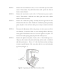
STEP 24:
Assemble the damper and the upper fireback. Place the re-gasketed
damper into its mating recess in the upper fireback. Insure that the damper
seats properly. Secure the damper shafts with 2 each, new damper tabs
and 2 each, hex head cap screw (¼-20x ½”). Insert the torsion bar through
its drilling in the upper fireback and swing the opposite end of the torsion
bar into its recess in the centre of the damper. Secure the torsion bar to the
damper centre with 1 each, new damper tab and 1 each, hex head cap
screw (¼-20x ½”). Secure the torsion bar to the upper fireback with 1
each, torsion bar clip and 1 each, hex head cap screw (¼”-20x ½”) and 1
each, standard flat washer (¼”). Operate the damper through its full range
of movement using the end of the torsion bar. If binding occurs, correct
by filing or grinding. Do not bend the torsion bar, tabs, or clips.
STEP 25:
Install the upper fireback and damper assembly. Start the left end into
position first; insuring that the torsion bar end is above the opening in the
left air/wear plate. Push the entire assembly upward into its cement
channel in the stove top. Align the drillings in the upper fireback with the
tapped holes in the right and left air/wear plates. Secure with 4 each, hex
head cap screws (¼-20x1”) and 4 each, standard flat washers (¼”).
STEP 26:
Install the damper actuator link and the damper handle rod. Place the long
end of the actuator link (with the short curved end pointing towards the
stove front and down) onto the end of the damper torsion bar. Move the
bar behind the ear of the damper linkage access opening in the left
air/wear plate. Place 1 each, narrow flat washer (3/8”) on the long end of
STEP 26 Cont: the damper handle rod. Insert the long end of the damper handle rod
through its drilling in the left stove end. Insert the shot end of the damper
actuator link. Align the linkage properly and check operation for binding
and/or stoppage.
STEP 27:
Install the damper handle stub. Place the damper in the updraft position.
While maintaining pressure on the damper handle rod from inside the
stove, slide the damper handle stub onto the opposite end of the handle rod
and align the damper stub with the open or updraft mark on the stove end.
Tighten the set screw in the handle stub with the 5/32” Allen wrench.
Move the damper handle from the full open (updraft) position to the full
closed and locked (catalytic burn) position. Linkage should move freely
until approaching the locked position. The damper should seat fully into
the fireback when locked.
If the damper does not move freely, correct by filling or grinding the
suspect parts. Do not bend or force any damper linkage parts. If the
damper does not lock, correct this deficiency by first insuring tight and
proper assembly. If the deficiency persists, consider replacement of the
tabs, clip, torsion bar, actuator link and/or the damper handle rod.
STEP 28:
Install the damper link access panel. Cement the
mating surface on the access panel as indicated in
Fig.C-12. Place the access panel against its mating
surface on the left air/wear plate and upper fireback,
rear portion first. Secure with 2 each, socket, flat head
machine screws (¼-20x ½”). Check the damper
operation, if binding or stoppage occurs, correct the
problem. Do not force the linkage.
Fig. C-12 Damper Link
Access Panel
STEP 29:
Install the catalyst access panel. Secure with 4 each, Phillips round head
machine screws (¼-20x5/8”).
STEP 30:
Install the flue collar. Position the flue collar for either top or rear exit
secure with 2 each, Phillips round head machine screws (¼-20x1”).
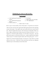
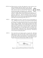
STEP 31:
Assemble and install the secondary inlet assembly. Holding the secondary
air probe and thermostat assembly with the probe facing away from you
and the mounting tab at 12 o’clock, the tab on the end of the thermostat
coil should be at 4 o’clock position, loosen the lock nuts on the probe shaft
and adjust the coil tab and the mounting tab to the 4 o’clock and 12
STEP 31 Cont: o’clock positions respectively and re-tighten the lock nuts. Insert the
double bent end of the secondary air link through the hole in the tab end of
the thermostat coil. Insert the single bent end of the secondary air link
through the hole in the tab on the secondary air flap. Insert the secondary
air probe through the drilling in the stove back and secure with 1 each,
Phillips pan head machine screw (10-20x ¼”). Secure the secondary air
flap to the stove back with 1 each, Phillips pan head machine screw (1024x ¼”) and 1 each, shim ring. Tighten the screw securing the air flap
until snug and back off ¼ turn. Insure that the secondary air flap moves
up and down freely and that the flap rests at or near the closed position.
See figure A-8.
Fig. A-8 Positioning of Secondary Air Probe & Flap
STEP 32:
Install the secondary air cover plate. Secure with 2 each, Phillips pan head
machine head screws (¼-20x3/8”).
STEP 33:
Assemble and install the ash door.
Screw the socket, button head cap screw
into the stepped side of the pawl (see
Fig.A-9). Thread the hex nut onto the
end of the socket, button head cap screw
and tighten finger tight against the flat
side of the pawl. Screw the socket set
screw into the handle shaft drilling of
the pawl. Slide the ash door handle
shaft through its drilling in the ash door.
Slide the pawl onto the ash door handle
shaft so that the pawl offset is opposite
the handle curve (see Fig.A-9). Insure
that the pawl is against the ash door and
Fig. A-9 Ash Door Handle Assembly
STEP 33 Cont.: that the handle turns without binding. Tighten the set screw in the pawl.
Thread the hex toplock jam nut onto the handle shaft and tighten it against
the pawl. With your 7/16” wrench, tighten the 3 cap screws attaching the
split half hinge to the ash drop slightly (just past finger tight). Tighten the
two cap screws holding the split half hinge together in the same manner.
Install the ash door hinge drilling into the clevis of the split half hinge.
Insert the clevis pin through the clevis from the bottom. Insert the hair pin
cotter through the drilling in the top of the clevis pin.
STEP 34:
Adjust the ash door. The design of the ash door split half hinge allows
three dimensional adjustment of the ash door. The 3 drillings in the ash
drop through which the ¼-20x ¾” cap screws pass before threading into
the rear half of the split half hinge are drilled oversized, allowing vertical
(up and down) and depth (in or out) adjustment. The 2 drillings in the rear
half of the split half hinge through which the ¼-20 ¾” cap screws pass
before threading into the front (clevis) half of the split half hinge are also
drilled oversized, allowing vertical (up and down) and horizontal (side to
side) adjustment.
Close the ash door tightly and re-open it. Check the gasket area of the
door to insure that the gasket mates evenly all the way around the door
with the front edge of the ash drop and front lip of the stove bottom.
Adjust the door by tapping side to side and up and down with the rubber
mallet. When the door is properly centered, tighten the two ¼-20x ¾” cap
screws that fasten the split half hinge together. Close and latch the ash
door. Starting at the handle (right) side of the ash door face, rap the door
face sharply from right to left across the lower face of the door with the
rubber mallet at approximately a 45 degree angle. Tighten the three ¼20x ¾” cap screws that fasten the split half hinge to the ash drop. Adjust
the ash door pawl assembly for a good firm latch by turning the socket
button head cap screw in or out and locking it with the lock nut.
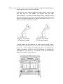
Test the door seal by placing 6 pieces of note paper evenly spaced, 3
pieces along the top and 3 pieces along the bottom of the door between the
door and the ash drop edge and closing and latching the door (see Fig.A10). Attempt to move the pieces of note paper from side to side. Attempt
to pull the note paper out of the joints. The note paper should not move at
all from side to side and should rest being pulled out of the joints almost to
the point of tearing. If the note paper moves from side to side or can
easily be pulled out of the joints, the door is not properly sealed. Readjust the ash door following the above procedure.
Fig. A-10 Ash Door Seal Test
STEP 35:
Install the ash pan bracket on the ash door. Secure with 2 each, hex head
cap screws (¼-20x ½”) and 4 each, (2 per cap screw) standard flat washers
(¼”). Tighten the cap screws finger tight. Close and open the ash door. If
the bracket contacts the ash drop, adjust the bracket by tapping it left or
right as required so that no metal to metal contact occurs when opening
and closing the ash door. Tighten the cap screws. Insert the ash pan into
the bracket and close and open the ash door. If the ash pan contacts the
bottom of the ash drop or the underside of the stove bottom, gently bend
the ash pan bracket up or down as required.
STEP 36:
Install the flat grate. Narrow dimension toward the rear of the stove, flat
side up.
STEP 37:
install the andirons. Secure with 2 each, hex head cap screws (¼-20x½”)
stainless steel and 2 each, stainless steel flat washers (¼”).
STEP 38:
Assemble the doors. At this point in time, the doors should have been
completely disassembled, stripped of old gasketing, cleaned, re-painted
and completely re-gasketed. Place the doors face down on a clean, flat
surface with a clean rag protecting the painted door faces. Insert the outer
glass panes. Insert the Encore Gasket with wire insert (pre-formed)
spreading the gasket against the cast frame all the way around. Insert the
inner glass panes. Secure the glass with glass retainer clips (4 per door)
and 4 each, Phillips pan head machine screws (10-24x ¼”). The short
glass retainer clip goes on the lower centre of each door. The upper centre
glass retainer on the right door is secured by the right door manifold.
Install the right and left door manifolds. Screw the Phillips pan head
machine screw (10-20 ¾”) all the way into the narrow end of each
manifold until it seats.
STEP 38 Cont: Back each screw out of its manifold 4 complete turns. Screw the manifold
to the door until snug. Secure the wide end of each manifold to the inside
door face with 2 each, Phillips pan head machine screws (10-20x ¾”).
Remember to place the upper centre glass retainer clip under the wide end
of the right door manifold. Install the right and left door hinge bosses.
Centre the bosses and secure with 3 each, hex head leveler bolts – (¼-20x
½” flat head) and 3 each, ¾” o.d. flat washers (¼”). Tighten just past
finger tight. Install the upper (long) hinge pins in the right and left hinge
bosses by tapping them into their drillings with a brass faced hammer.
Install the jump rings on the upper shoulder of the lower (short) door pins
and tap the pins into their drillings in the bottom of the right and left hinge
bosses with a brass faced hammer. Insert the socket set screw (7/1620x1”) into its tapped hole in the top centre of the right door. Screw the
set screw through the door (from inside) until the socket end is flush with
the bottom of the gasket channel. Re-cement the gasket.
STEP 39:
Cleaning, washing and taping the stove. With the putty knife, clean all
outside stove seams and joints of any thermocement leakage or spillage.
Draw a bucket or pail of hot water and with a sponge or soft rag; wash the
stove down, especially the outside seams and joints. Remove all visible
dirt and thermocement. Mask the damper handle stub and thermostat
handle with masking tape. Cover the secondary air system cover plate and
the printed plates on the catalyst access panel with masking tape.
STEP 40:
Paint the stove. Use Vermont Castings High Temperature Stove Paint
(black), part # 000-0031. Follow directions printed on the can and paint
the entire outside of the stove.
STEP 41:
Install and adjust the doors. Locate the hinge pin drillings in the upper
sides of the stove front. Insert the upper hinge pins of each door into its
drillings, swing the bottom of each door against the stove front and drop
the lower hinge pins into their drillings. Close the doors and check the
gasket seating between the doors and the stove front mating surface. Both
door bottoms should be level and even with each other. There should be
no metal to metal contact between the doors and the stove front or
between the right and left doors. The vertical seam between the doors
should be even from top to bottom. Adjust the doors by gently tapping
left or right and up and down. When a good gasket seal is achieved and
doors are even and level, tighten the leveling bolts (3 per door). Install the
door handle by screwing it onto the socket set screw protruding from the
top centre of the right door. With the door handle flush against the door
face, the handle tab should enter its slot in the top centre of the stove front
STEP 41 Cont: and when turned counter clockwise against its stop, should pull both doors
snugly against the stove front and each other.
If the doors are loose when the handle tab is fully engaged, open the right
door and turn the door handle 360 degrees (one full turn)
counterclockwise. Close the door and attempt to latch. If the tab will not
enter its opening in the stove front, remove the handle from the door and
either file or grind the handle face of the tab at an angle (see Fig.A-11) a
little at a time until a tight latch is obtained.
Fig. A-11 Door Handle
W/Tab Before Grinding
Fig. A-11 Door Handle
W/Tab After Grinding
If, when latched, the door handle is not in the vertical position, remove
and replace the split roll pin (3/16”x1”) in the handle tab opening of the
stove front. After leveling and plumbing the doors and adjusting the
latching mechanism, check the seal of both doors by applying the
“notepaper test” (see Fig.A-12). If the doors fail the test, re-adjust the
hinge bosses, latch the doors and re-test.
STEP 42:
Assemble and install the griddle. Place the griddle quadrants on the
underside of the griddle and secure with 2 each, hex head cap screws (¼20x½”). Install the griddle handle assembly and secure with 1 each, hex
nut (10-24) and 1 each #10 washer. Install the griddle on the stove and tap
gently around its perimeter with a rubber mallet to seat the gasket.
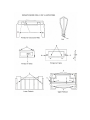
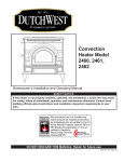
APPENDIX #1
SUGGESTED FIX FOR BENT DAMPER CLIPS ENCORE 0028/2140
DIAGRAM
KEY
PART
NUMBER
QUANTITY
DESCRIPTION
A
160-1036
1
Torsion Bar Clip
B
120-2474
2
¼” Flat Washer
C
120-1310
2
¼-20 Plain Nut
D
120-0446
1
¼-20 x 1¼” Socket SS
APPENDIX #2
YEARLY MAINTENANCE SUGGESTIONS
The 0028 and 2140 Defiant Encore is a sophisticated combustion machine, and regular
“fine tuning” will give you the full benefits of its operating potential.
GENERAL CHECKLIST
• Inspect the chimney for blockage such as squirrels, nests, branches, etc.
• Have a chimney sweep inspect and clean the chimney if necessary.
• Inspect the connector pipe for wear and replace if necessary.
• Make sure each length of connector pipe, if single wall, is joined by three
screws.
• Inspect the stove gaskets for wear using the “Dollar Bill Test” and replace as
necessary.
• Remove any surface rust and repaint any heat shields or chimney connectors.
INSPECT THE CATALYTIC COMBUSTOR
Fly ash can accumulate on top of the combustor. If sufficient quantity accumulates, it
can block the flow of gases through it and cause restriction and back-puffing.
• Remove the four Philips head fasteners which secure the cast iron panel to the
rear of the stove. Remove the panel..
• Gently pry off the refractory catalyst cover with a flat blade screwdriver.
• Visually inspect the catalyst for fly ash using a small mirror. It is not necessary to
remove the catalyst for this purpose.
• If the catalyst appears coated with fly ash, carefully remove the catalytic
combustor. The catalyst element is contained within a stainless steel jacket (can).
You may have to grasp the element with two flat bladed screwdrivers at the
element ends to draw the element from the stove. If the honeycomb is clogged,
take the element outside for cleaning. Blow gently through the honeycomb.
Inspect the element. Although small hairline cracks will not affect performance,
the element should essentially be intact. If elements are broken or missing, the
catalyst should be replaced. If the catalyst is in good shape and all the fly ash has
been removed, re-install the combustor in the stove by sliding it into the the
opening, making sure that it is resting on the stainless steel support ledge which is
visible before installation of the catalyst. Gently reinstall the catalyst cover. The
“U” shaped ridge should be toward the stove with the open end down. The
refractory cover should be flush with the other refractory surfaces. Replace the
access panel and securely tighten the fasteners.
CLEAN THE SECONDARY AIR PASSAGE
Fly ash can also accumulate in the secondary air passageway. Once a year it is a good
idea to vacuum out this opening.
• The secondary air cover is located immediately below the catalyst access panel.
Remove the two Phillips pan head screws holding the secondary air cover to the
back of the stove.
• Push the secondary air flap up to the open position with your finger and place a
vacuum nozzle at the opening.
• Replace the cover.
CHECK THE GASKET SEALS ON THE DAMPER AND ASH PAN DOOR
In addition to the gaskets on the front doors and griddle, the Encore has seals on the
damper and the ash pan door that are important for proper stove performance.
• Test the ash pan door seal by placing by placing pieces of note paper or dollar
bills at three locations across both the bottom and top of the door. Close and latch
the door. If the paper is easily moved or pulled out, the door is not properly
sealed and the gasket should be replaced using 3/8” fiberglass gasket.
• To replace the gasket, first pull out the old gasket. Clean the channel with a wire
brush. Next, lay the new gasket in place and trim to the correct length. Place a
1/8” bead of gasket cement in the channels and press the trimmed gasket into
place. Close the door. Seat the gasket in the door by pushing in hard against the
door (a rubber mallet may be used). Open the door and remove any excess
cement that has squeezed out around the gasket.
• The door gasketing will compress within the first few weeks, so you will need to
readjust the latch. To do this, loosen the hex lock nut with an open end wrench
and back off the striker screw. Tighten the screw until the door seals securely and
the latch still operates. Then tighten the hex lock nut.
CHECK THE DAMPER
The Encore’s damper is designed to snap into a locked position. When closing the
damper, push the handle past the point at which you feel resistance until it snaps into the
locked position.
• Place several pieces of note paper along the top and bottom of the damper and
lock the damper.
• As with the ash pan door, if the pieces can be easily pulled out (very little
resistance), replace the 5/16” gasket.
• This is most easily done through the flue collar opening (the flue collar may also
be removed). Pull out the old gasket and clean the channel.
• Place a thin bead of gasket cement in the channel.
• Cut a length of gasket to size and press it into the channel.
• Allow the cement to harden for 24 hours before firing the stove.
CLEAN THE GLASS
The Encore’s glass is designed to stay free of carbon deposits, even under low fire
conditions. However, periodic cleaning is necessary to prevent permanent etching of the
glass with fly ash or carbon. Use a commercial wood stove glass cleaner supplied by
your dealer or you may with to make your own cleaning paste. Take a damp cloth and
dip it into the fine grey ash in the ash pan. Wipe the glass with this and a paste will form
and continue until the glass is cleaned. Buff with a clean cloth.