1
Keysight U2751A USB
Modular Switch Matrix
Programmer’s
Reference
Guide
Notices
® Keysight Technologies 2008, 2015
Warranty
No part of this manual may be reproduced in
any form or by any means (including electronic storage and retrieval or translation
into a foreign language) without prior agreement and written consent from Keysight
Technologies as governed by United States
and international copyright laws.
The material contained in this document is provided “as is,” and is subject to being changed, without notice,
in future editions. Further, to the maximum extent permitted by applicable
law, Keysight disclaims all warranties, either express or implied, with
regard to this manual and any information contained herein, including
but not limited to the implied warranties of merchantability and fitness for
a particular purpose. Keysight shall
not be liable for errors or for incidental or consequential damages in connection with the furnishing, use, or
performance of this document or of
any information contained herein.
Should Keysight and the user have a
separate written agreement with
warranty terms covering the material
in this document that conflict with
these terms, the warranty terms in the
separate agreement shall control.
Manual Part Number
U2751-90022
Edition
Edition 2, January 2015
Keysight Technologies
1400 Fountaingrove Parkway
Santa Rosa, CA 95403
Safety Notices
Technology Licenses
The hardware and/or software described in
this document are furnished under a license
and may be used or copied only in accordance with the terms of such license.
Restricted Rights Legend
U.S. Government Restricted Rights. Software and technical data rights granted to
the federal government include only those
rights customarily provided to end user customers. Keysight provides this customary
commercial license in Software and technical data pursuant to FAR 12.211 (Technical
Data) and 12.212 (Computer Software) and,
for the Department of Defense, DFARS
252.227-7015 (Technical Data - Commercial
Items) and DFARS 227.7202-3 (Rights in
Commercial Computer Software or Computer Software Documentation).
II
CAUTION
A CAUTION notice denotes a hazard. It calls attention to an operating procedure, practice, or the like
that, if not correctly performed or
adhered to, could result in damage
to the product or loss of important
data. Do not proceed beyond a
CAUTION notice until the indicated
conditions are fully understood and
met.
WA R N I N G
A WARNING notice denotes a
hazard. It calls attention to an
operating procedure, practice, or
the like that, if not correctly performed or adhered to, could result
in personal injury or death. Do not
proceed beyond a WARNING
notice until the indicated conditions are fully understood and
met.
U2751A Programmer’s Reference Guide
Contents
1
Introduction to Programming 1
Introduction to the SCPI Language 2
SCPI Conventions and Data Formats 3
Command Separators 5
Querying Parameter Settings 5
SCPI Command Terminators 6
IEEE-488.2 Common Commands 6
Channel List Parameters 6
2
SCPI Status Registers 9
SCPI Status Registers 10
Status Byte Register 11
Standard Event Register 12
3
DIAGnostic Subsystem 13
DIAGnostic:RELay:CYCLes? 14
DIAGnostic:RELay:CYCLes:CLEar 15
4
ROUTe Subsystem 17
ROUTe:CLOSe 18
ROUTe:CLOSe? 19
ROUTe:OPEN 20
ROUTe:OPEN? 21
5
SYSTem Subsystem 23
SYSTem:CDEScription? 24
SYSTem:ERRor? 25
SYSTem:VERSion? 27
U2751A Programmer’s Reference Guide
III
Contents
IV
6
IEEE-488.2 Common Commands 29
*CLS 30
*ESE/*ESE? 31
*ESR? 34
*IDN? 36
*OPC/*OPC? 38
*RST 40
*SRE/*SRE? 41
*STB? 44
*TST? 46
7
Error Messages 47
Error Messages 48
Error List 48
U2751A Programmer’s Reference Guide
Keysight U2751A USB Modular Switch Matrix
Programmer’s Reference Guide
1
Introduction to Programming
Introduction to the SCPI Language 2
SCPI Conventions and Data Formats 3
Command Separators 5
Querying Parameter Settings 5
SCPI Command Terminators 6
IEEE-488.2 Common Commands 6
Channel List Parameters 6
This chapter introduces the remote programming basics of the U2751A
USB modular switch matrix. The programming commands provide the
means to control this instrument remotely via a PC.
1
Introduction to Programming
Introduction to the SCPI Language
SCPI, also known as the Standard Commands for Programmable
Instruments, is an ASCII-based instrument command language designed for
test and measurement instruments. SCPI commands are based on a
hierarchical structure, also known as a tree system. In this system,
associated commands are grouped together under a common node or root,
thus forming subsystems. A portion of the ROUTe subsystem is shown
below to illustrate the tree system.
ROUTe:
CLOSe (@<ch_list>)
CLOSe? (@<ch_list>)
OPEN (@<ch_list>)
OPEN? (@<ch_list>)
ROUTe is the root keyword of the command, CLOSe and OPEN are
second-level keywords. A colon ( : ) separates a command keyword from a
lower-level keyword.
For example, in the above syntax statement, ROUT and ROUTE are both
acceptable forms. You can use upper- or lower-case letters. Therefore,
ROUTE, Rout, and rout are all acceptable. Other forms, such as ROU, are
not valid and will generate an error.
2
U2751A Programmer’s Reference Guide
Introduction to Programming
1
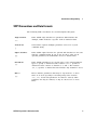
SCPI Conventions and Data Formats
The following SCPI conventions are used throughout this guide.
Angle brackets
< >
Vertical bar
|
Square brackets
[ ]
Parenthesis
( )
Braces
{ }
Items within angle brackets are parameter abbreviations. For
example, <NR1> indicates a specific form of numerical data.
Vertical bars separate multiple parameter choices for a given
command string.
Items within square brackets are optional. The brackets are not sent
with the command string. If you do not specify a value for an
optional parameter, the instrument chooses a default value.
Items within parentheses are used in place of the usual parameter
types to specify a channel list. The notation (@1:3) specifies a
channel list that consists of channels 1, 2, and 3. The notation
(@1,3) specifies a channel list that includes only channels 1 and 3.
Braces indicate parameters that may be repeated zero or more
times. It is used especially for showing arrays. The notation
<A>{,<B>} shows that parameter "A" must be entered, while
parameter "B" may be omitted, or may be entered one or more
times.
U2751A Programmer’s Reference Guide
3
1
Introduction to Programming
Data programmed or queried from the instrument is ASCII. The data may
be numerical or character string.
<NR1>
Digits with an implied decimal point assumed at the right of the
least-significant digit. Example: 273
<NR2>
Digits with an explicit decimal point. Example: 27.3
<NR3>
Digits with an explicit decimal point and an exponent. Example: 2.73E+02
<NRf>
Extended format that includes <NR1>, <NR2>, and <NR3>.
Examples: 273
<NRf+>
27.3
2.73E+02
Expanded decimal format that includes <NRf> and MIN, MAX.
Examples: 273
27.3
2.73E+02 MAX
MIN and MAX are the minimum and maximum limit values that are implicit
in the range specification for the parameter.
4
<Bool>
Boolean Data. Can be numeric (0, 1) or named (OFF, ON).
<SPD>
String Program Data. Programs string parameters enclosed in single or
double quotes.
<CPD>
Character Program Data. Programs discrete parameters. Accepts both the
short form and long form.
<SRD>
String Response Data. Returns string parameters enclosed in single or
double quotes.
<CRD>
Character Response Data. Returns discrete parameters. Only the short form
of the parameter is returned.
<AARD>
Arbitrary ASCII Response Data. Permits the return of undelimited 7-bit
ASCII. This data type has an implied message terminator.
<Block>
Arbitrary Block Response Data. Permits the return of definite length and
indefinite length arbitrary response data. This data type has an implied
message terminator.
U2751A Programmer’s Reference Guide
Introduction to Programming
1
Command Separators
A colon ( : ) is used to separate a command keyword from a lower-level
keyword. You must insert a blank space to separate a parameter from a
command keyword. If a command requires more than one parameter, you
must separate adjacent parameters using a comma as shown below.
ROUT:CLOS (@101)
A semicolon ( ; ) is used to separate commands within the same
subsystem and also minimize typing. For example, sending the following
command string.
ROUT:OPEN (@101); CLOS (@102)
... is the same as sending the following two commands.
ROUT:OPEN (@101)
ROUT:CLOS (@102)
Use a colon and semicolon to link commands from different subsystems.
For example, in the following command string, an error is generated if you
do not use both the colon and semicolon.
ROUT:CLOS (@101);: DIAG:REL:CYCL:CLE (@101)
Querying Parameter Settings
You can query the current value of most parameters by adding a question
mark ( ? ) to the command. For example, the following command closes
channel 101.
ROUT:CLOS (@101)
You can then query the current range settings by sending:
ROUT:CLOS? (@101)
U2751A Programmer’s Reference Guide
5
1
Introduction to Programming
SCPI Command Terminators
A command string sent to the instrument must terminate with a <new
line> (<NL>) character. The IEEE-488 End-Of-Identify (EOI) message is
interpreted as a <NL> character and can be used to terminate a command
string in place of a <NL> character. A <carriage return> followed by a
<NL> is also accepted. Command string termination will always reset the
current SCPI command path to the root level.
IEEE-488.2 Common Commands
The IEEE-488.2 standard defines a set of common commands that perform
functions such as reset, self-test, and status operation. Common commands
always begin with an asterisk ( * ), are three characters in length, and
may include one or more parameters. The command keyword is separated
from the first parameter by a blank space. Use a semicolon ( ; ) to
separate multiple commands as shown below.
*RST; *CLS; *ESE 32; *OPC?
Channel List Parameters
The channel parameter is required to address one or more channels.
It has the following syntax.
(@<ch_list> [,<ch_list>][,<ch_list>])
You can also specify a range of sequential channels as follows.
(@<start_ch_list>:<end_ch_list>)
The following command closes channel 101 on the module.
ROUT:CLOS (@101)
6
// For single channel selection.
U2751A Programmer’s Reference Guide
Introduction to Programming
1
The following command closes channels 101, 103, and 107 on the module.
ROUT:CLOS (@101,103,107)
// By using ‘,’ for individual channel
selection in the same row.
The following commands close channels 101, 303, and 405 on the module.
ROUT:CLOS (@101,303,405)
ROUT:CLOS (@101, 303, 405)
// By using ‘,’ for individual channel
selection in different row.
// The command is still valid with or
without the spaces in between each
channel.
The following command closes channels 201 through 203.
ROUT:CLOS (@201:203)
// By using ‘:’ for multiple channel
selection in the same row.
The following command closes channels 106 through 303.
ROUT:CLOS (@106:303)
// By using ‘:’ for multiple channel
selection in different row.
The following command closes channels 101 and 201 through 203 and 303.
ROUT:CLOS (@101,201:203,303) // By using ‘,’ and ‘:’ for multiple
channel selection.
The following command closes channels 101 through 108 and 205 through
308.
ROUT:CLOS (@101:108,205:308) // By using ‘:’ and ‘,’ for multiple
channel selection.
U2751A Programmer’s Reference Guide
7
1
Introduction to Programming
When you specify a range of channels, the first and last channel in the
range must be valid and any channel within the range that is invalid will
be ignored (no error will be generated). Query results are returned in the
order they are specified in the list.
NOTE
8
When adding a channel list parameter to a query, you must include a space character
between the query indicator (?) and channel list parameter such as ROUT:CLOS?
(@<ch_list>). Otherwise error –103, ''Invalid separator'' will occur.
U2751A Programmer’s Reference Guide
Keysight U2751A USB Modular Switch Matrix
Programmer’s Reference Guide
2
SCPI Status Registers
SCPI Status Registers 10
Status Byte Register 11
Standard Event Register 12
This chapter explains the SCPI status registers that record various
instrument conditions of the U2751A USB modular switch matrix.
2
SCPI Status Registers
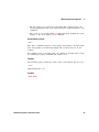
SCPI Status Registers
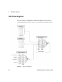
The U2751A uses the Status Byte and Standard Event register groups to
record a variety of instrument conditions. The figure below shows the
relationship between various registers in the U2751A SCPI status system.
Error Queue
SYSTem:ERRor?
Status Byte Register
Output Buffer
C
EN
''OR''
Serial Poll
*STB?
Summary Bit (RQS)
Standard Event Register
EV
*SRE
*SRE?
EN
Operation Complete
Query Error
Device Error
Execution Error
Command Error
''OR''
Power On
*ESR?
*ESE
*ESE?
Figure 2-1 Status system diagram
10
U2751A Programmer’s Reference Guide
SCPI Status Registers
2
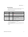
Status Byte Register
The Status Byte summary register reports conditions from the other status
registers. The bits are not cleared when you read the register.
Bit Definitions: Status Byte Register
Bit number
Decimal value
Definition
0 Not Used
1
Always zero.
1 Not Used
2
Always zero.
2 Error Queue
4
There is at least one error code in the error queue. Use the
SYSTem:ERRor? command to read and clear the error from the
queue.
3 Not Used
8
Always zero.
4 Message Available
16
Data is available in the instrument's output buffer.
5 Standard Event
32
One or more bits are set in the Standard Event register (bits must be
enabled, refer to the *ESE command).
6 Master Summary
64
One or more bits are set in the Status Byte register and may
generate a Request for Service (RQS). Bits must be enabled using
the *SRE command.
7 Not Used
128
Always zero.
The Status Byte summary register will be cleared when:
• you execute the clear status (*CLS) command
• querying the Standard Event register (*ESR? command will clear only
bit 5 in the summary register)
The Status Byte Enable register is cleared when you execute the *SRE 0
command.
U2751A Programmer’s Reference Guide
11
2
SCPI Status Registers
Standard Event Register
The Standard Event register reports the following types of instrument
events: power-on detected, command syntax errors, command execution
errors, self-test or calibration errors, query errors, or when an *OPC
command is executed. All of these conditions can be reported in the
Standard Event summary bit through enable register. To set the enable
register mask, key in a decimal value to the register using the event status
enable (*ESE)command.
Bit Definitions: Standard Event Register
Bit number
Decimal value
Definition
0 Operation Complete
1
All commands prior to and including *OPC have been executed.
1 Not Used
2
Always zero.
2 Query Error
4
The instrument tried to read the output buffer but it was empty. Or, a
new command line was received before a previous query has been
read. Or, both the input and output buffers are full (an error in the
–400 range has been generated).
3 Device Error
8
A self-test or device error occurred (an error in the –300 range or
any positive error has been generated). For a complete listing of the
error messages, refer to Chapter 7, “Error Messages” on page 47.
4 Execution Error
16
An execution error occurred (an error in the –200 range has been
generated).
5 Command Error
32
A command syntax error occurred (an error in the –100 range has
been generated).
6 Not Used
64
Always zero.
7 Power On
128
Power has been turned off and on since the last time the event
register was read or cleared.
The Standard Event register is cleared when:
• you execute the clear status (*CLS)command
• querying the event register using the event status register (*ESR?)
command
The Standard Event Enable register is cleared when you execute the
*ESE 0 command.
NOTE
12
Please refer to Chapter 6, “IEEE-488.2 Common Commands” on page 29 for more details of
the common IEEE commands mentioned above.
U2751A Programmer’s Reference Guide
Keysight U2751A USB Modular Switch Matrix
Programmer’s Reference Guide
3
DIAGnostic Subsystem
DIAGnostic:RELay:CYCLes? 14
DIAGnostic:RELay:CYCLes:CLEar 15
This chapter explains how the DIAGnostic command subsystem operates.
3
DIAGnostic Subsystem
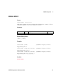
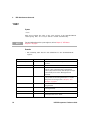
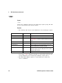
DIAGnostic:RELay:CYCLes?
Syntax
DIAGnostic:RELay:CYCLes? (@<ch_list>)
This query returns the cycle count of the relay at the specified channels.
Parameter
Item
Type
Range of values
Default value
<ch_list>
NR1
101 through 408
N/A
Returned Query Format
<NR1> [,<NR1>]
Example
DIAG:REL:CYCL? (@101,104,103) //Queries the number of relay cycles.
Typical Response: 10000,100,10
14
U2751A Programmer’s Reference Guide
DIAGnostic Subsystem
3
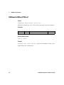
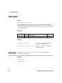
DIAGnostic:RELay:CYCLes:CLEar
Syntax
DIAGnostic:RELay:CYCLes:CLEar (@<ch_list>)
This command sets the relay cycle counter of the specified channel(s) to
zero.
Parameter
Item
Type
Range of values
Default value
<ch_list>
NR1
101 through 408
N/A
Example
DIAG:REL:CYCL:CLE (@101)
NOTE
This command is used to clear the relay cycle counter when the user changes a new relay.
U2751A Programmer’s Reference Guide
15
3
16
DIAGnostic Subsystem
U2751A Programmer’s Reference Guide
Keysight U2751A USB Modular Switch Matrix
Programmer’s Reference Guide
4
ROUTe Subsystem
ROUTe:CLOSe 18
ROUTe:CLOSe? 19
ROUTe:OPEN 20
ROUTe:OPEN? 21
The ROUTe command subsystem is used to control the matrix relays.
4
ROUTe Subsystem
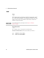
ROUTe:CLOSe
Syntax
ROUTe:CLOSe (@<ch_list>)
This command closes the specified channels in the channel list. The
channel number represents the matrix cross-point of a row (one digit) and
a column (two digits). For example, channel 308 represents cross-point at
row 3 and column 8.
Parameter
Item
Type
Range of values
Default value
<ch_list>
NR1
101 through 408
N/A
Examples
NOTE
ROUT:CLOS (@101)
// For single channel selection.
ROUT:CLOS (@201:203)
// By using ‘:’ for multiple channel
selection in the same row.
Please refer to Chapter 1, “Channel List Parameters” on page 6 for more possible
combinations of this command.
See Also
ROUTe:CLOSe?
ROUTe:OPEN
18
U2751A Programmer’s Reference Guide
ROUTe Subsystem
4
ROUTe:CLOSe?
Syntax
ROUTe:CLOSe? (@<ch_list>)
This query returns the state of the specified channels. It returns "1" if the
channel is closed or "0" if the channel is opened.
Parameter
Item
Type
Range of values
Default value
<ch_list>
NR1
101 through 408
N/A
Returned Query Format
<NR1> [,<NR1>]
Examples
ROUT:CLOS? (@101)
// Returns 1 if close, 0 if open.
Typical Response: 1
ROUT:CLOS? (@101,105,207,304) // Returns 1 if close, 0 if open.
Typical Response: 1,1,1,0
ROUT:CLOS? (@108:203,307:404) // Returns 1 if close, 0 if open.
Typical Response: 1,1,1,0,0,1,1,0,1,1
See Also
ROUTe:CLOSe
U2751A Programmer’s Reference Guide
19
4
ROUTe Subsystem
ROUTe:OPEN
Syntax
ROUTe:OPEN (@<ch_list>)
This command opens the specified channels in the channel list. The
channel number represents the matrix cross-point of a row (one digit) and
a column (two digits). For example, channel 308 represents cross-point at
row 3 and column 8.
Parameter
Item
Type
Range of values
Default value
<ch_list>
NR1
101 through 408
N/A
Examples
ROUT:OPEN (@106:303)
// By using ‘:’ for multiple channel
selection in different row.
ROUT:OPEN (@101,201:203,303) // By using ‘,’ and ‘:’ for multiple
channel selection.
NOTE
Please refer to Chapter 1, “Channel List Parameters” on page 6 for more possible
combinations of this command.
See Also
ROUTe:CLOSe
ROUTe:OPEN?
20
U2751A Programmer’s Reference Guide
ROUTe Subsystem
4
ROUTe:OPEN?
Syntax
ROUTe:OPEN? (@<ch_list>)
This query returns the state of the specified channels. It returns "1" if the
channel is opened or "0" if the channel is closed.
Parameter
Item
Type
Range of values
Default value
<ch_list>
NR1
101 through 408
N/A
Returned Query Format
<NR1> [,<NR1>]
Examples
ROUT:OPEN? (@101)
// Returns 1 if open, 0 if close.
Typical Response: 1
ROUT:OPEN? (@101,205,307,404) // Returns 1 if open, 0 if close.
Typical Response: 1,1,1,0
ROUT:OPEN? (@108:203,307:404) // Returns 1 if open, 0 if close.
Typical Response: 1,1,1,0,0,1,1,0,1,1
See Also
ROUTe:OPEN
U2751A Programmer’s Reference Guide
21
4
22
ROUTe Subsystem
U2751A Programmer’s Reference Guide
Keysight U2751A USB Modular Switch Matrix
Programmer’s Reference Guide
5
SYSTem Subsystem
SYSTem:CDEScription? 24
SYSTem:ERRor? 25
SYSTem:VERSion? 27
This chapter explains the functions of the SYSTem command subsystem.
5
SYSTem Subsystem
SYSTem:CDEScription?
Syntax
SYSTem:CDEScription?
This query returns the slot number and chassis number (chassis ID).
Remarks
• It is only applicable when the U2751A is used in the modular
instrument chassis.
• If the U2751A is used as a standalone module, the query will return a
default slot number ''+7'' and chassis number ''+0''.
• Please refer to the U2781A Modular Instrument Chassis User's Guide for
the details.
Returned Query Format
<NR1>, <NR1>
Examples
The following query returns the slot number ''+2'' and chassis number ''+5''.
SYST:CDES?
Typical Response: +2, +5
If the U2751A is used as a standalone module, the following query returns
the default slot number ''+7'' and chassis number ''+0''.
SYST:CDES?
Typical Response: +7, +0
24
U2751A Programmer’s Reference Guide
SYSTem Subsystem
5
SYSTem:ERRor?
Syntax
SYSTem:ERRor?
This query returns the error number and its corresponding message string
from the instrument’s error queue. A record of up to 20 errors can be
stored in the instrument's error queue. The USB remote interface I/O
session has its own interface-specific error queue. Errors that appear in
the error queue of the I/O session cause the error.
For a complete listing of the U2751A's error messages, refer to Chapter 7,
“Error Messages” on page 47.
Remarks
• This query is only used when the user is controlling the relay using
own software.
• Errors are retrieved in first-in, first-out (FIFO) order where the first
error returned is the first error that was stored. Once you have read all
the interface-specific errors, the errors in the global error queue are
retrieved.
• If more than 20 errors have occurred, the last error stored in the queue
(the most recent error) is replaced with –350, "Queue overflow". No
additional errors are stored until you remove errors from the queue. If
no errors have occurred when you read the error queue, the instrument
responds with 0, "No error".
• Error conditions are also summarized in the Status Byte Register. For
more information on the SCPI Status System for the U2751A, refer to
Chapter 2, “SCPI Status Registers” on page 9.
• The interface-specific and global error queues are cleared by the clear
status (*CLS) command and when power is cycled. The errors are also
cleared when you read the error queue. The error queue is not cleared
by a factory reset (*RST) command.
U2751A Programmer’s Reference Guide
25
5
SYSTem Subsystem
Returned Query Format
<NR1>, <SRD>
Example
SYST:ERR?
Typical Response: –330, "Self-test failed"
26
U2751A Programmer’s Reference Guide
SYSTem Subsystem
5
SYSTem:VERSion?
Syntax
SYSTem:VERSion?
This command returns the version of the Standard Commands for
Programmable Instruments (SCPI) standard in which the instrument
complies with.
Returned Query Format
<SRD>
Example
The command returns a string in the form of "YYYY.V", where "YYYY"
represents the year of the version and "V" represents a version for that
year (e.g. 1997.0).
Typical Response: 1997.0
U2751A Programmer’s Reference Guide
27
5
28
SYSTem Subsystem
U2751A Programmer’s Reference Guide
Keysight U2751A USB Modular Switch Matrix
Programmer’s Reference Guide
6
IEEE-488.2 Common Commands
*CLS 30
*ESE/*ESE? 31
*ESR? 34
*IDN? 36
*OPC/*OPC? 38
*RST 40
*SRE/*SRE? 41
*STB? 44
*TST? 46
This chapter contains information on the IEEE-488.2 Common (*)
Commands supported by the U2751A. It also describes the universal
command statements which form the nucleus of the GPIB programming
understood by all instruments in the network. When combined with the
programming language codes, the commands provide all management and
data communication instructions for the system.
6
IEEE-488.2 Common Commands
*CLS
Syntax
*CLS
This command is used to clear the event registers in all register groups
and also clears the error queue.
NOTE
For more information on the system registers, refer to Chapter 2, “SCPI Status
Registers” on page 9.
Example
The following command clears the event register bits.
*CLS
30
U2751A Programmer’s Reference Guide
IEEE-488.2 Common Commands
6
*ESE/*ESE?
Syntax
*ESE <enable_value>
This command enables the bits in the enable register for the Standard
Event register group. The selected bits are then reported to bit 5 of the
Status Byte register.
*ESE?
This will query the Standard Event enable register group.
NOTE
For more information on the system registers, refer to Chapter 2, “SCPI Status
Registers” on page 9.
Parameter
Item
Type
Range of values
Default value
<enable_value>
NR1
A decimal value that corresponds to the
binary-weighted sum of the bits in the register.
Refer to the table below.
This is a required
parameter.
U2751A Programmer’s Reference Guide
31
6
IEEE-488.2 Common Commands
Remarks
• The following table lists the bit definitions for the Standard Event
register.
Bit number
Decimal value
Definition
0 Operation Complete
1
All commands prior to and including *OPC have been
executed.
1 Not Used
2
Always zero.
2 Query Error
4
The instrument tried to read the output buffer but it was
empty. Or, a new command line was received before a
previous query has been read. Or, both the input and output
buffers are full (an error in the –400 range has been
generated).
3 Device Error
8
A self-test or device error occurred (an error in the –300 range
or any positive error has been generated). For a complete
listing of the error messages, refer to Chapter 7, “Error
Messages” on page 47.
4 Execution Error
16
An execution error occurred (an error in the –200 range has
been generated).
5 Command Error
32
A command syntax error occurred (an error in the –100 range
has been generated).
6 Not Used
64
Always zero.
7 Power On
128
Power has been turned off and on since the last time the
event register was read or cleared.
• Use the <enable_value> parameter to specify which bits will be
enabled. The specified decimal value corresponds to the binary-weighted
sum of the bits you wish to enable in the register. For example, to
enable bit 2 (decimal value = 4), bit 4 (decimal value = 16), and bit 5
(decimal value = 32), the corresponding decimal value would be 52 (4 +
16 + 32).
• The clear status (*CLS) command will not clear the enable register but
it clears all the bits in the event register.
32
U2751A Programmer’s Reference Guide
IEEE-488.2 Common Commands
6
Returned Query Format
<NR1>
The query command reads the enable register and returns a decimal value
that corresponds to the binary-weighted sum of all the bits set in the
register.
For example, if bit 3 (decimal value = 8) and bit 7 (decimal value = 128)
are enabled, the query command will return ''+136''.
Examples
The following command enables bit 4 (decimal value = 16) in the enable
register. If an execution error occurs, this condition will be reported to
the Status Byte register (bit 5 will be set to high).
*ESE 16
The following query returns the bits enabled in the register.
*ESE?
Typical Response: +16
See Also
*ESR?
U2751A Programmer’s Reference Guide
33
6
IEEE-488.2 Common Commands
*ESR?
Syntax
*ESR?
This query returns the value of the event register of the Standard Event
status group. Once it is read, it will be cleared automatically.
NOTE
For more information on the system registers, refer to Chapter 2, “SCPI Status
Registers” on page 9.
Remarks
• The following table lists the bit definitions for the Standard Event
register.
34
Bit number
Decimal value
Definition
0 Operation Complete
1
All commands prior to and including *OPC have been
executed.
1 Not Used
2
Always zero.
2 Query Error
4
The instrument tried to read the output buffer but it was
empty. Or, a new command line was received before a
previous query has been read. Or, both the input and output
buffers are full (an error in the –400 range has been
generated).
3 Device Error
8
A self-test or device error occurred (an error in the –300 range
or any positive error has been generated). For a complete
listing of the error messages, refer to Chapter 7, “Error
Messages” on page 47.
4 Execution Error
16
An execution error occurred (an error in the –200 range has
been generated.
5 Command Error
32
A command syntax error occurred (an error in the –100 range
has been generated).
6 Not Used
64
Always zero.
7 Power On
128
Power has been turned off and on since the last time the
event register was read or cleared.
U2751A Programmer’s Reference Guide
IEEE-488.2 Common Commands
6
• For any event to be reported on the Status Byte register group, the
corresponding bits in the event register must be enabled using the *ESE
command.
• Once a bit is set, it will remain set until cleared by reading the event
register or the clear status (*CLS) command.
Returned Query Format
<NR1>
The query command reads the event register and returns a decimal value
that corresponds to the binary-weighted sum of all the bits set in the
register.
For example, if bit 3 (decimal value = 8) and bit 7 (decimal value = 128)
are enabled, the query command will return "+136".
Example
The following query returns the value of the event register (bit 4 is set).
*ESR?
Typical Response: +16
See Also
*ESE/*ESE?
U2751A Programmer’s Reference Guide
35
6
IEEE-488.2 Common Commands
*IDN?
Syntax
*IDN?
This command reads the instrument's identification string which contains
four comma-separated fields. The first field is the manufacturer's name,
the second is the model number of the instrument, the third is the serial
number, and the fourth is the firmware revision which contains three
firmwares separated by dashes.
NOTE
For more information on the system registers, refer to Chapter 2, “SCPI Status
Registers” on page 9.
Returned Query Format
<AARD>
The command returns a string with the following format.
KEYSIGHT TECHNOLOGIES,U2751A,<Serial Number>,Va.aa-b.bb-c.cc
a.aa
b.bb
c.cc
36
= Mainframe revision number
= Matrix code revision number
= Boot code revision number
U2751A Programmer’s Reference Guide
IEEE-488.2 Common Commands
6
Example
The following query returns the instrument's identification string.
*IDN?
Typical Response:
KEYSIGHT TECHNOLOGIES,U2751A,MY12345678,V1.00-1.00-1.00
If the system is unable to recognize the model number or serial number,
the *IDN? command will return the default value of the model and serial
number. Please perform self-test for error check.
Typical Response:
KEYSIGHT TECHNOLOGIES,U2751X,MY1234567X,V1.00-1.00-1.00
U2751A Programmer’s Reference Guide
37
6
IEEE-488.2 Common Commands
*OPC/*OPC?
Syntax
*OPC
The command is mainly used for program synchronization. It causes the
instrument to set the OPC bit (bit 0) of the Standard Event Status register
when the instrument has completed all pending operation sent before the
*OPC command.
*OPC?
This query returns "1" to the output buffer at the completion of all the
pending operation. *OPC? command does not suspend processing of
commands.
NOTE
For more information on the system registers, refer to Chapter 2, “SCPI Status
Registers” on page 9.
Remarks
• Please take note of the difference between *OPC and *OPC?.
• Pending operation have completed when:
• all commands sent before *OPC have completed. Commands are
executed sequentially (the execution of a command has to be
completed before the next one is being executed)
• all triggered actions have completed
• *OPC does not prevent the processing of subsequent commands,
however, the OPC bit will not be set until all pending operation have
completed.
Returned Query Format
<NR1>
The command returns "1" to the output buffer.
38
U2751A Programmer’s Reference Guide
IEEE-488.2 Common Commands
6
Examples
The following command waits until the closing of channel 101 command
has been executed and then sets the “Operation Complete” bit.
ROUT:CLOS (@101); *OPC
See Also
*ESE/*ESE?
*ESR?
U2751A Programmer’s Reference Guide
39
6
IEEE-488.2 Common Commands
*RST
Syntax
*RST
This command is used to reset the relays. It will turn all relays to open
state.
Example
The following command resets the instrument.
*RST
40
U2751A Programmer’s Reference Guide
IEEE-488.2 Common Commands
6
*SRE/*SRE?
Syntax
*SRE <enable_value>
This command enables the bits in the enable register for the Status Byte
register group. Once enabled, the corresponding bits may generate a
Request for Service (RQS) in the Status Byte register. This RQS event may
generate a "call back" to your application as a type of asynchronous
interrupt.
*SRE?
The query command reads the enable register and returns a decimal value
that corresponds to the binary-weighted sum of all the bits set in the
register. For example, if bit 2 (decimal value = 4) and bit 6 (decimal value
= 64) are enabled, the query command will return "+68".
NOTE
For more information on the system registers, refer to Chapter 2, “SCPI Status
Registers” on page 9.
Parameter
Item
Type
Range of values
Default value
<enable_value>
NR1
A decimal value that corresponds to the
binary-weighted sum of the bits in the
register. Refer to the table below.
This is a required parameter.
U2751A Programmer’s Reference Guide
41
6
IEEE-488.2 Common Commands
Remarks
• The following table lists the bit definitions for the Status Byte register.
Bit number
Decimal value
Definition
0 Not Used
1
Always zero.
1 Not Used
2
Always zero.
2 Error Queue
4
There is at least one error code in the error queue. Use the
SYSTem:ERRor? command to read and clear the error from the
queue.
3 Not Used
8
Always zero.
4 Message Available
16
Data is available in the instrument's output buffer.
5 Standard Event
32
One or more bits are set in the Standard Event register (bits
must be enabled, refer to the *ESE command).
6 Master Summary
64
One or more bits are set in the Status Byte register and may
generate a Request for Service (RQS). Bits must be enabled
using the *SRE command.
7 Not Used
128
Always zero.
• Use the <enable_value> parameter to specify which bits will be
enabled. The specified decimal value corresponds to the binary-weighted
sum of the bits you wish to enable in the register. For example, to
enable bit 1 (decimal value = 2), bit 3 (decimal value = 8), and bit 6
(decimal value = 64), the corresponding decimal value would be 74 (2 +
8 + 64).
• The Status Byte Enable register will be cleared when you execute the
*SRE 0 command.
Returned Query Format
<NR1>
The query command reads the enable register and returns a decimal value
that corresponds to the binary-weighted sum of all the bits set in the
register.
For example, if bit 3 (decimal value = 8) and bit 7 (decimal value = 128)
are enabled, the query command will return "+136".
42
U2751A Programmer’s Reference Guide
IEEE-488.2 Common Commands
6
Examples
The following command enables bit 4 (decimal value = 16) in the enable
register.
*SRE 16
The following query returns the bits enabled in the register.
*SRE?
Typical Response: +16
See Also
*STB?
U2751A Programmer’s Reference Guide
43
6
IEEE-488.2 Common Commands
*STB?
Syntax
*STB?
Queries the condition register for the Status Byte register group. The bits
are not cleared when you read the register.
Remarks
• The following table lists the bit definitions for the Status Byte register.
Bit number
Decimal value
Definition
0 Not Used
1
Always zero.
1 Not Used
2
Always zero.
2 Error Queue
4
There is at least one error code in the error queue. Use the
SYSTem:ERRor? command to read and clear the error from the
queue.
3 Not Used
8
Always zero.
4 Message Available
16
Data is available in the instrument's output buffer.
5 Standard Event
32
One or more bits are set in the Standard Event register (bits
must be enabled, refer to the *ESE command).
6 Master Summary
64
One or more bits are set in the Status Byte register and may
generate a Request for Service (RQS). Bits must be enabled
using the *SRE command.
7 Not Used
128
Always zero.
• The Status Byte condition register is cleared when you execute the
clear status (*CLS) command. Clearing an event register will clear the
corresponding bits in the Status Byte summary register (bit 5).
• The Status Byte Enable register is cleared when you execute the
*SRE 0 command.
44
U2751A Programmer’s Reference Guide
IEEE-488.2 Common Commands
6
Returned Query Format
<NR1>
The query command reads the condition register and returns a decimal
value which corresponds to the binary-weighted sum of all the bits set in
the register (refer to the table under Remarks). For example, if bit 1
(decimal value = 2) and bit 4 (decimal value = 16) are set (and the
corresponding bits are enabled), this command will return "+18".
Example
The following command reads the condition register (bits 3 and 4 are set).
*STB?
Typical Response: +24
See Also
*CLS
*SRE/*SRE?
U2751A Programmer’s Reference Guide
45
6
IEEE-488.2 Common Commands
*TST?
Syntax
*TST?
This query command performs a self-test of the instrument and returns a
pass/fail indication. This self-test is the same as the self-test conducted
when the matrix is powered-on. When self-test fails, error will be reported.
Returned Query Format
<NR1>
The command returns "+0" (all tests passed) or "+1" (one or more tests
failed).
Example
The following command performs a self-test and returns a pass/fail
indication.
*TST?
Typical Response: +0
46
U2751A Programmer’s Reference Guide
Keysight U2751A USB Modular Switch Matrix
Programmer’s Reference Guide
7
Error Messages
Error Messages 48
Error List 48
This U2751A SCPI command errors are summarized in this chapter.
7
Error Messages
Error Messages
Error messages are created once a command error or an erroneous
condition has been detected.
• Errors are retrieved in first-in, first-out (FIFO) order.
• Errors are cleared as you read them.
• If too many errors occur, the last error stored in the queue (the most
recent error) will be replaced with –350, "Queue overflow". No
additional errors will be stored until you remove the errors from the
queue. If no errors occur when you read the error queue, the
instrument will respond with 0, "No error".
• SYSTem:ERRor? will read and clear one error from the queue.
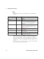
Error List
The table below contains the list of command errors.
Table 7-1 Command errors
Error
Command errors (these errors set the Standard Event Status register bit #5)
–101
Invalid character
An invalid character was found in the command string. You may have inserted a character such as #, $, or
% in a command keyword or within a parameter.
–102
Syntax error
Invalid syntax was found in the command string. You may have inserted a blank space before or after a
colon in the command header, or before a comma.
–103
Invalid separator
An invalid separator was found in the command string. Check for proper usage of , ; :
–108
Parameter not allowed
More parameters were received than expected for the command. You may have entered an extra
parameter, or you have added a parameter to a command that does not accept a parameter.
–109
Missing parameter
Fewer parameters were received than expected for the command. You may have omitted one or more
parameters that are required for this command.
48
U2751A Programmer’s Reference Guide
Error Messages
7
Table 7-1 Command errors (continued)
Error
Command errors (these errors set the Standard Event Status register bit #5)
–112
Program mnemonic too long
The header contains more than 12 characters.
–113
Undefined header
A command was received that is not valid. You may have misspelled the command or it may not be a valid
command. If you are using the short form of the command, remember that it may contain up to four letters.
–121
Invalid character in number
An invalid character was found in the number specified for a parameter value.
Example: *ESE #2
–148
Character data not allowed
A discrete parameter was received, but a string or numeric parameter was expected.
–158
String data not allowed
A character string was received, but is not allowed for this command.
The execution errors are listed in the table below.
Table 7-2 Execution errors
Error
Execution errors (these errors set the Standard Event Status register bit #4)
–222
Data out of range
A data element could not be executed because the value was outside the valid range.
–223
Too much data
A data element was received that contains more data than the instrument can handle.
–224
Illegal parameter value
A discrete parameter was received which was not a valid choice for the command. You may have used an
invalid parameter choice.
–224
Illegal parameter value, ranges must be positive
The range entered must be in ascending order.
U2751A Programmer’s Reference Guide
49
7
Error Messages
The following table shows the list of device-specific errors.
Table 7-3 Device-specific errors
Error
Device-specific errors (these errors set the Standard Event Status register bit #3)
–330
Self-test failed
The self-test fails.
–350
Queue overflow
The error queue is full and another error has occurred which could not be recorded.
The list of query errors is shown in the following table.
Table 7-4 Query errors
Error
Query errors (these errors set the Standard Event Status register bit #2)
–410
Query INTERRUPTED
A command was received which sends data to the output buffer but the output buffer contained data from
a previous command (the previous data is not overwritten). The output buffer is cleared when power has
been turned off.
–420
Query UNTERMINATED
An invalid query command was received.
–440
Query UNTERMINATED after indefinite response
More than one query command within a command string. The system will only return the data for the first
query command. Example: *IDN?; :SYST:VERS?
50
U2751A Programmer’s Reference Guide
Error Messages
7
The table below contains the list of instrument errors.
Table 7-5 Instrument errors
Error
Instrument errors (these errors set the Standard Event Status register bit #3)
+112
Channel list: channel number out of range
An input of less than 1 or more than 4 for the row numbers will cause this error message to appear such as
001and 501. Also, the column numbers which are less than 1 or more than 8 will generate this error such
as 100 and 109.
+309
Incorrectly formatted channel list
The '@' symbol as the first character in the parameter does not exist. It contains illegal symbols other than
':', ','. Example: ROUT:CLOS (@101;#&).
It has symbol ':' again. Example: ROUT:CLOS (@101:107:).
Self-test errors are displayed in the following table.
Table 7-6 Self-test errors
Error
Self-test errors (these errors set the Standard Event Status register bit #3)
+671
EEPROM failed
The communication between the controller and EEPROM fails.
+672
ISP failed
The communication between the controller and USB controller fails.
+673
CPLD failed
The communication between the controller and CPLD fails.
U2751A Programmer’s Reference Guide
51
7
52
Error Messages
U2751A Programmer’s Reference Guide
www.keysight.com
Contact us
To obtain service, warranty or technical
support assistance, contact us at the following
phone numbers:
United States:
(tel) 800 829 4444 (fax) 800 829 4433
Canada:
(tel) 877 894 4414 (fax) 800 746 4866
China:
(tel) 800 810 0189 (fax) 800 820 2816
Europe:
(tel) 31 20 547 2111
Japan:
(tel) (81) 426 56 7832 (fax) (81) 426 56
7840
Korea:
(tel) (080) 769 0800 (fax) (080) 769 0900
Latin America:
(tel) (305) 269 7500
Taiwan:
(tel) 0800 047 866 (fax) 0800 286 331
Other Asia Pacific Countries:
(tel) (65) 6375 8100 (fax) (65) 6755 0042
Or visit Keysight worlwide web at:
www.keysight.com/find/assist
Product specifications and descriptions in
this document subject to change without notice.
This information is subject to change without notice.
© Keysight Technologies 2008, 2015
Edition 2, January 2015
*U2751-90022*
U2751-90022
www.keysight.com