1
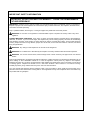
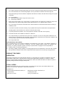
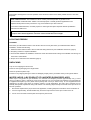
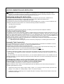
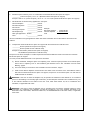
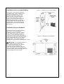
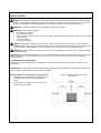
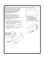
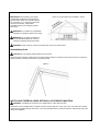
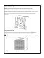
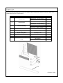
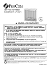
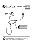
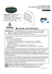
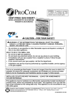
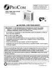
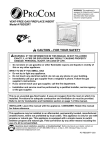
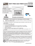
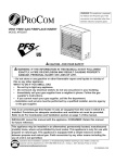
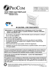
VENT-FREE GAS FIREPLACE
Model # PC32VFC & PC36VFC
CAUTION – FOR YOUR SAFETY
WARNING: IF THE INFORMATION IN THIS MANUAL IS NOT FOLLOWED
EXACTLY, A FIRE MAY RESULT CAUSING PROPERTY DAMAGE, PERSONAL
INJURY, OR LOSS OF LIFE.
–
Do not store or use gasoline or other flammable vapors and liquids in vicinity of
this or any other appliance.
WHAT TO DO IF YOU SMELL GAS
· Do not try to light any appliance.
· Do not touch any electrical switch; do not use any phone in your building.
· Immediately call your gas supplier from a neighbor’s phone. Follow the gas
supplier’s instructions.
· If you cannot reach your gas supplier, call the fire department.
– Installation and service must be performed by a qualified installer, service agency
or the gas supplier.
FOR USE ONLY WITH A LISTED GAS-FIRED UNVENTED DECORATIVE ROOM
HEATER NOT TO EXCEED 40,000 BTU/HR. DO NOT BUILD A WOOD FIRE.
Carefully review the instructions supplied with the decorative type unvented room
heater for the minimum fireplace size requirement.
DO NOT INSTALL AN APPLIANCE IN THIS FIREBOX UNLESS THIS FIREBOX MEETS
THE MINIMUM DIMENSIONS REQUIRED FOR THE INSTALLATION.
This firebox has been tested and approved under ANSI Z21.91 for use with any ANSI
Z21.11.2 approved gas logs.
Questions about installation, operation, or troubleshooting? Before returning to your retailer, contact our
customer service department at 1-877-886-5989, 8:00 a.m.- 4:30p.m., EST, Monday-Friday or e-mail
[email protected].
PC32VFC-651 and PC36VFC-701
TABLE OF CONTENTS
Important Safety Information ...........................................................................................................................................3
Product Feature...............................................................................................................................................................4
Local Codes ....................................................................................................................................................................4
Locating Firebox..............................................................................................................................................................5
Air For Combustion and Ventilation.................................................................................................................................6
Installation .......................................................................................................................................................................9
Replacement Parts........................................................................................................................................................13
WARNING: READ THE INSTALLATION & OPERATION INSTRUCTIONS BEFORE USING THIS APPLIANCE
IMPORTANT: Read instructions and warnings carefully before starting installation. Failure to follow these instructions
may result in a possible fire hazard and will void the warranty.
PRODUCT SPECIFICATIONS
32’ and 36” Models
Figure 1
Model
A
B
C
D
E
F
G
H
I
PC32VFC
2.381"
18.515"
19°
24.060"
7.567"
21.382"
20.718"
31.732"
29.323"
PC36VFC
2.397"
18.870"
25°
28.770"
6.622"
26.740"
25.949"
36.031"
33.630"
2
IMPORTANT SAFETY INFORMATION
INSTALLER: DO NOT DISCARD THIS MANUAL – LEAVE FOR HOMEOWNER’S
FUTURE REFERENCE.
IMPORTANT: Read this owner’s manual carefully and completely before trying to assemble, operate, or service this
fireplace. Improper use of this fireplace can cause serious injury or death from burns, fire, explosion, electrical shock,
and carbon monoxide poisoning.
Only a qualified installer, service agent, or local gas supplier may install and service this product.
WARNING: Do not store or use gasoline or other flammable vapors or liquids in the vicinity of this or any other
appliance.
CARBON MONOXIDE POISONING: Early signs of carbon monoxide poisoning resemble the flu with headaches,
dizziness, or nausea. If you have these signs, the fireplace may not be working properly. Get fresh air immediately!
Have fireplace serviced. Some people are more affected by carbon monoxide than others. These include pregnant
women, people with heart or lung disease, people who are anemic, those under the influence of alcohol, and those
living in high altitudes.
WARNING: Any change to this fireplace or its controls can be dangerous.
WARNING: Do not allow fans to blow directly into fireplace. Avoid any drafts that alter burner flame patterns.
WARNING: Do not use a blower insert, heat exchange insert or other accessory not approved for use with this
firebox.
Due to high temperatures, the appliance should be located out of traffic and away from furniture and draperies. Do not
place clothing or other flammable material on or near the appliance. Never place any objects in the fireplace.
Fireplace becomes very hot when running fireplace. Keep children and adults away from hot surfaces to avoid burns
or clothing ignition. Fireplace will remain hot for a time after shutdown. Allow surfaces to cool before touching.
Carefully supervise young children when they are in the room with the firebox.
You must operate this fireplace with the fireplace screen, hood if provided, in place. Make sure these parts are in
place and screens are closed before running firebox. The supplied hood may not be replaced with a hood which may
be provided with a log fireplace.
3
1.
Do not place Propane/LP supply tank(s) inside any structure. Propane/LP supply tank(s) must be placed outdoors.
2.
Do not use this firebox as a wood-burning fireplace. Use only decorative unvented room heaters (log set).
3.
Keep all air openings in front and bottom of fireplace clear and free of debris. This will ensure enough air for proper
combustion.
4.
Do not run fireplace:
l
Where flammable liquids or vapors are used or stored.
l
Under dusty conditions.
5.
Before using furniture polish, wax, carpet cleaner, or similar products, turn fireplace off. If heated, the vapors from
these products may create a white powder residue within burner box or on adjacent walls or furniture.
6.
Do not use firebox if it has been under water due to shock hazard that could result with the blower accessory (if
installed) in place.
7.
Turn firebox off and let cool before servicing. Only a qualified service person should service and repair firebox.
8.
Operating firebox above elevations of 4,500 feet could cause pilot outage.
9.
To prevent performance problems, do not use propane/LP fuel tank of less than 100 lb. capacity.
10. This firebox should not be installed in a bedroom or bathroom.
11. Do not add extra logs or ornaments such as pine cones, vermiculite, or rock wool. Using these added items can
cause sooting. Do not add lava rock around base. Rock and debris could fall into the control area of fireplace. After
servicing, always replace screen before operating fireplace.
12. Use only provided hood.
QUALIFIED INSTALLING AGENCY
Only a qualified agency should perform installation and replacement of gas piping, gas utilization equipment or
accessories, and repair and servicing of equipment. The term “qualified agency” means any individual, firm,
corporation, or company that either in person or through a representative is engaged in and is responsible for:
a)
Installing, testing, or replacing gas piping or
b)
Connecting, installing, testing, repairing, or servicing equipment; that is experienced in such work; that is familiar
with all precautions required; and that has complied with all the requirement of the authority having jurisdiction.
PRODUCT FEATURES
OPERATION
This firebox is designed for use with approved ANSI Z21.11.2 decorative type unvented room fireplaces. (Physical
size limitations apply. Refer to minimum firebox requirements supplied with log fireplace.) It requires no outside
venting or chimney making installation easy and inexpensive. When used without the blower, the firebox requires no
electricity making it ideal for emergency backup heat.
LOCAL CODES
Install and use fireplace with care. Follow all codes. In the absence of local codes, use the latest edition of The
National Fuel Gas Code, ANSI Z223.1, also known as NFPA 54*.
*Available from:
American National Standards Institute, lnc.
1430 Broadway
New York, NY 10018
National Fire Protection Association, lnc.
1 Batterymarch Park
Quincy, MA 02269-9101
4
This fireplace is designed for vent-free operation. State and local codes in some areas prohibit the use of vent-free
fireplaces.
State of Massachusetts: The installation must be made by a licensed plumber or gas fitter in the
Commonwealth of Massachusetts. Sellers of unvented propane or natural gas-fired supplemental room
fireplaces shall provide to each purchaser a copy of 527 CMR 30 upon sale of the unit.
In the State of Massachusetts, unvented propane or natural gas-fired space fireplaces shall be prohibited in
bedrooms and bathrooms.
In the State of Massachusetts the gas cock must be a T-handle type. The State of Massachusetts
requires that a flexible appliance connector cannot exceed three feet in length.
LOCATING FIREBOX
PLANNING
Plan where you will install the firebox. This will save time and money later when you install the firebox. Before
installation, consider the following:
1. Where the firebox will be located. Allow for wall and ceiling clearances (see Installation Clearances, page 9).
2. Everything needed to complete installation.
3. These models CANNOT be installed in a bedroom unless the maximum BTU rating of the installed vent-free log set
is less than 10,000 Btu/Hr.
4. Proper air for combustion and ventilation (page 6).
UNPACKING
1.Rip of f the wrapping film around unit.
2.Remove the top packaging and 4 angle beads.
3.Remove protective plastic wrap
4.Check for any shipping damage. If firebox is damaged,promptly inform your dealer where you bought the firebox.
WATER VAPOR: A BY-PRODUCT OF UNVENTED ROOM FIREPLACES
Water vapor is a by-product of gas combustion. An unvented room fireplace produces approximately one (1) ounce
(30 mL) of water for every 1,000 BTUs (.3 kw) of gas input per hour. An unvented room fireplace is recommended as
a supplemental fireplace (a room) rather than a primary heat source (an entire house). In most supplemental heat
applications, the water vapor does not create a problem. In most applications, the water vapor enhances the low
humidity atmosphere experienced during cold weather. The following steps will help insure that water vapor does not
become a problem:
1.
Be sure the fireplace is the proper size for the application, including adequate combustion air and circulation air.
2.
If there is high humidity, the dehumidifier may be used to help lower the water vapor content of the air.
3.
Do not use an unvented room fireplace as the primary heat source.
5
AIR FOR COMBUSTION AND VENTILATION
WARNING: This fireplace should not be installed in a confined space or unusually tight construction unless
provisions are provided for adequate combustion and ventilation air. Read the following instructions to insure
proper fresh air for this and other fuel-burning appliances in your home.
PRODUCING ADEQUATE VENTILATION
This fireplace shall not be installed in a room or space unless the required volume of indoor combustion air is
provided by the method described in the NATIONAL FUEL GAS CODE, ANSI Z223.1/NFPA 54, the
INTERNATIONAL FUEL GAS CODE, or applicable local codes.
The following are excerpts from National Fuel Gas Code, NFPA 54/ANSI Z223.1, Section 5.3, Air for Combustion and
Ventilation. All spaces in homes fall into one of the three following ventilation classifications:
1.
Unusually Tight Construction
2.
Unconfined Space
3.
Confined Space
The information on pages 6 through 8 will help you classify your space and provide adequate ventilation.
Confined and Unconfined Space
The National Fuel Gas Code, ANSI Z223.1 defines a confined space as a space whose volume is less than 50 cu. ft. per
1,000 BTU/hr (4.8 m^3 per kw) of the aggregate input rating of all appliances installed in that space and an unconfining
space as a space whose volume is not less than 50 cu. ft. per 1,000 BTU/hr (4.8 m^3 per kw) of the aggregate input
rating of all appliances installed in that space. Rooms communicating directly with the space in which the appliances are
installed*, through openings not furnished with doors, are considered a part of the unconfined space.
This fireplace shall not be installed in a confined space or unusually tight construction unless provisions are provided
for adequate combustion and ventilation air.
·
Adjoining rooms are connecting only if there are doorless passageways or ventilation grills between them
Unusually Tight Construction
The air that leaks around doors and windows may provide enough fresh air for combustion and ventilation. However,
in buildings of unusually tight construction, you must provide additional fresh air.
Unusually tight construction is defined as construction where:
a) walls and ceilings
exposed to 2the outside atmosphere have a continuous water vapor retarder with a rating of one
-11
perm (6x10 kg per pa-sec-m ) or less with openings gasketed or sealed and
b) weather stripping has been added on windows that can be opened and on doors and
c) caulking or sealants are applied to areas such as joints around window and door frames, between sole plates and
floors, between wall-ceiling joints, between wall panels, at penetrations for plumbing, electrical, and gas lines, and at
other openings.
If your home meets all of the three criteria above, you must provide additional fresh air. See “Ventilation Air from
Outdoors” (page 8). If your home does not meet all of the three criteria above, proceed to “Determining Fresh-Air Flow
for Fireplace Location”.
DETERMINING FRESH-AIR FLOW FOR FIREPLACE LOCATION
Determining if You Have a Confined or Unconfined Space
Use this worksheet to determine if you have a confined or unconfined space.
Space: Includes the room in which you will install fireplace plus any adjoining rooms with doorless passageways or
ventilation grills between the rooms.
1.
Determine the volume of the space Length × Width × Height = cu. ft. (volume of space) Example: Space size 20 ft.
(length) × 16 ft. (width) × 8 ft. (ceiling height) = 2560 cu. ft. (volume of space)
If additional ventilation to adjoining room is supplied with grills or openings, add the volume of these rooms to the
total volume of the space.
6
2.
Divide the space volume by 50 cu. ft. to determine the maximum BTU/hr the space can support.
__________ (Volume of space) ÷ 50 cu. ft. = (Maximum BTU/hr the space can support)
Example: 2560 cu. ft. (volume of space) ÷ 50 cu. ft. = 51.2 or 51,200 (maximum BTU/hr the space can support)
3.
Add the BTU/hr of all fuel burning appliances in the space.
Vent-free fireplace
_____________ BTU/hr
Gas water fireplace*
_____________ BTU/hr
Gas furnace
_____________ BTU/hr
Vented gas fireplace
_____________ BTU/hr
Gas fireplace logs
_____________ BTU/hr
Other gas appliances*+ BTU/hr
Total
Example:
Gas water fireplace
30,000 BTU/hr
Vent-free fireplace + 26,000 BTU/hr
Total
= 56,000 BTU/hr
= _____________ BTU/hr
*Do not include direct-vent gas appliances. Direct-vent draws combustion air from the outdoors and vents to the
outdoors.
4.
Compare the maximum BTU/hr the space can support with the actual amount of BTU/hr used.
__________ BTU/hr (maximum the space can support)
__________ BTU/hr (actual amount of BTU/hr used).
Example: 51,200 BTU/hr (maximum the space can support)
56,000 BTU/hr (actual amount of BTU/hr used)
The space in the above example is a confined space because the actual BTU/hr used is more than the maximum
BTU/hr the space can support.
You must provide additional fresh air. Your options are as follows:
a)
Rework worksheet, adding the space of an adjoining room. If the extra space provides an unconfined space,
remove door to adjoining room or add ventilation grills between rooms. See “Ventilation Air from inside
Building,” page 8.
b)
Vent room directly to the outdoors. See “Ventilation Air from Outdoors”, Page 8.
c)
Install a lower BTU/hr fireplace if lower BTU/hr size makes room unconfined. If the actual BTU/hr used is
less than the maximum BTU/hr the space can support, the space is an unconfined space. You will need no
additional fresh air ventilation.
WARNING: If the area in which the fireplace may be operated is smaller than that defined as an unconfined
space or if the building is of unusually tight construction, provide adequate combustion and ventilation air by one
of the methods described in the National Fuel Gas Code, ANSI Z223.1/NFPA 54, Air for Combustion and
Ventilation, or applicable local codes.
WARNING: If the area in which the fireplace may be operated does not meet the required volume for indoor
combustion air, combustion and ventilation air shall be provided by one of the methods described in the
NATIONAL FUEL GAS CODE, ANSI Z223.1/NFPA 54, the INTERNATIONAL FUEL GAS CODE, or applicable
local codes.
7
Figure 2 - Ventilation Air from Inside Building
Ventilation Air from Inside Building
This fresh air would come from adjoining
unconfined space. When ventilating to an
adjoining unconfined space, you must
provide two permanent openings: one
within 12 inches of the wall connecting
the two spaces (see options 1 and 2,
Figure 2). You can also remove door into
adjoining room (see option 3, Figure 2).
Follow the National Fuel Gas Code NFPA
54/ANSI Z223.1. Air for Combustion and
Ventilation for required size of ventilation
grills or ducts.
Ventilation Air from Outdoors
Provide extra fresh air by using ventilation
grills or duct. You must provide two
permanent openings: one within 12 inches
of the ceiling and one within 12 inches of
the floor. Connect these items directly to
the outdoors or spaces open to the outdoors.
These spaces include attics and crawl spaces.
Follow the National Fuel Gas Code NFPA
54/ANSI Z223.1. Air for Combustion and
Ventilation for required size of ventilation grills or ducts.
Figure 3 - Ventilation Air from Outdoors
IMPORTANT: Do not provide openings for
inlet or outlet air into attic if attic has a
thermostat-controlled power vent. Heated
air entering the attic will activate the
power vent. Rework worksheet, adding the
space of the adjoining unconfined space. The
combined spaces must have enough fresh air to
supply all appliances in both spaces.
8
INSTALLATION
NOTICE: This fireplace is intended for use as supplemental heat. Use this fireplace along with your primary heating
system. Do not install this fireplace as your primary heat source. If you have a central heating system, you may run
system’s circulating blower while using fireplace. This will help circulate the heat throughout the house.
WARNING: A qualified technician must install fireplace. Follow all local codes.
WARNING: Never install the fireplace:
·
in a bedroom or bathroom
·
in a recreational vehicle
·
Where curtains, furniture, clothing, or other flammable objects are less than 42 inches from the front, top or sides
of the fireplace.
·
in high traffic areas
·
in windy or drafty areas
CAUTION: This fireplace creates warm air currents. These currents move heat to wall surfaces next to fireplace.
Installing fireplace next to vinyl or cloth wall coverings or operating fireplace where impurities (such as tobacco smoke,
aromatic candles, cleaning fluids, oil or kerosene lamps, etc.) in the air exist, may cause walls to discolor.
WARNING: Maintain the minimum clearances. If you can, provide greater clearances from floor, ceiling and adjoining
side and back walls.
IMPORTANT: Vent-free fireplaces add moisture to the air. Although this is beneficial, installing fireplace in rooms without
enough ventilation air may cause mildew to form from too much moisture. See Air for Combustion and Ventilation,
pages 6 through 8.
CLEARANCES TO COMBUSTIBLES
Carefully follow the instructions below. This fireplace is a wall mount unit designed to sit directly on the floor or on a
mantel base.
IMPORTANT: You must maintain minimum wall and ceiling clearances during installation. The minimum clearances are
shown in Figure 4. Measure from outermost point of fireplace.
Figure 4 – Minimum Clearance to Wall
and Ceiling
Minimum Wall and Ceiling Clearances (see Figure 4)
A. Clearances from outermost point of fireplace to any
combustible side wall should not be less than 7
inches.
B.
Clearances from the fireplace to the ceiling should
not be less than 42 inches.
9
NOTE: When fireplace is installed directly on carpeting, tile or other combustible material, other than wood flooring, the
fireplace must be installed on a metal or wood panel extending the full width and depth of the fireplace.
BUILT-IN FIREPLACE INSTALLATION
Figure 5 – Clearance to Combustibles
Built-in installation of this fireplace involves installing
fireplace into a framed-in enclosure. This makes
the front of the fireplace flush with wall. If installing
a built-in mantel above the fireplace, you must
follow the clearances shown in Figure 5.
Follow the instructions.
NOTICE: Surface temperatures of adjacent walls
and mantels become hot during operation. Walls
and mantels above the firebox may become hot
to the touch. If installed properly, these temperatures
meet the requirement of the national product standard.
Follow all minimum clearances shown in this
manual. See Figure 6.
1.
Frame in rough opening. Use dimensions shown in Figure 7
for the rough opening. If installing in a corner, use
dimensions shown in Figure 8 for the rough opening.
The height is 23.66(PC36VFC) & 28.11(PC32VFC), which is
the same as the wall opening above.
2.
Carefully set fireplace in front of rough opening with back of
fireplace inside wall opening.
3.
Install gas piping to firebox location. See Installing Gas Line,
on page 12 and Connecting to Gas Supply in log set
owner’s manual.
Figure 6
10
Figure 7 - Rough Opening for Installing in Wall
Figure 8 - Rough Opening for Installing in Corner
IMPORTANT: When finishing your firebox,
Combustible materials such as wall board,
gypsum board, sheet rock, drywall, plywood,
etc, must have ½ -in. clearance to the sides
and top of the firebox. Combustible
materials should never overlap the firebox
front facing.
WARNING: Do not allow any combustible
materials to overlap the firebox front facing.
WARNING: Do not allow combustible or
noncombustible materials to cover any
necessary openings like louvered slots.
WARNING: Never modify or cover the louvered slots on the front of the firebox.
Assembling Hood
CAUTION: Do not operate fireplace without hood in place.
Aim three holes on firebox panel at those on heat insulation board; fix the firebox with screws pre-set on its board by
directly inserting screwdriver into holes on top firebox panel.
Figure 9
INSTALLING FIREBOX USING OPTIONAL ACCESSORY MANTELS
WARNING: A qualified service person must install firebox. Follow all local codes.
This firebox may be installed using a cabinet mantel accessory against a wall in your home. The firebox and cabinet
mantel can be installed directly on the floor. A trim kit is included with the mantel accessories. Follow instructions with
mantel for installation.
11
INSTALLING GAS LINE
NOTI CE: A qualified service person must connect heater to gas supply. Follow all local codes.
IMPORTANT: See Connecting to Gas Supply in your log set owner’s manual for details on gas hookup.
You may run the gas line from either side of the firebox (see Figure 10). Decide which side you want to run the gas
line from.
Note: This is one option for installing shutoff valve. Check local codes for equipment shutoff valve location
requirements.
Figure 10
Equipment Shutoff
Valves (Install One)
Knock Out
Locations
(Knock Out
One Hole)
Gas Line Hole
Using optional fiber panels
There is a gas knockout in each side panel for the gas line to feed through. Determine on which side the gas
connection will be located. Using a utility knife or cutting blade, remove the identified gas knockout.
CAUTION: Do not use excessive force to remove the knockout. Too much force may damage the fiber panel.
Figure 11
1/2” Thick Liner
Firebrick Side Wall
Side View
Remove
This Area
KnockOut
12
REPLACEMENT PARTS
NOTE: Use only original replacement parts. This will protect your warranty coverage for parts replaced under
warranty.
PARTS UNDER WARRANTY
Contact authorized dealers of this product. If they can’t supply original replacement parts, call Customer Service toll
free at (1-877-886-5989) for referral information.
When calling Customer Service or your dealer, have ready:
·
Your name
·
Your address
·
Model and serial number of your fireplace
·
How fireplace was malfunctioning
·
Purchase date
·
Usually, we will ask you to return the defective part to the factory
PARTS NOT UNDER WARRANTY
Contact authorized dealers of this product. If they can’t supply original replacement part(s) call Customer Service toll
free at (1-877-886-5989) for referral information.
When calling Customer Service have ready:
·
Model number of your fireplace
·
The replacement part number
13
PARTS LIST
This list contains replaceable parts used in your fireplace. When ordering parts, follow the instructions listed under
Replacement Parts on 13 of this manual.
Part..
Description
Part #
QTY
1
Screen Rod
PC32VFC-132 (PC32VFC)
1
PC36VFC-132 (PC36VFC)
1
2
Draw screen
PC32VFC-131 (PC32VFC)
2
PC36VFC-131 (PC36VFC)
2
3
Louver assembly
PC32VFC-000B (PC32VFC)
1
PC36VFC-120B (PC36VFC)
1
4
Switch
PF06-0400-A
1
5
Magnet
FE32A155B
1
6
Blower fixing panel
PC32VFC-127
1
7
Blower bracket
PC32VFC-126
1
8
Blower Assembly
FIB100
1
9
Hood
FBD32D201
1
PC36VFC-117
1
9
Printed in China
14