1
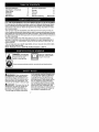
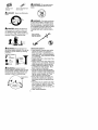
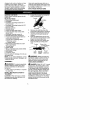
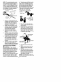
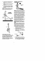
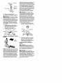
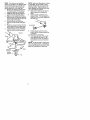
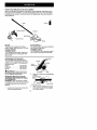
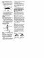
Instruction Manual
BRUSHCUTTER ATTACHMENT
Model No.
358.792442
NOT DESIGNED
FOR USE
WITH
POWERHEADS
ELECTRIC
•
Safety
•
Assembly
•
•
Operation
Maintenance
•
Parts List
•
Espahol
DANGER:
Read and follow all Safety Rules and Operating
Instructions before first use of this product.
For answers to your questions about this product: Call 7
am-7 pm, Mon.-Sat., or 10 am-7 pm, Sun.
1-800-235-5878
Sears, Roebuck
530164834
1/22/04
and Co., Hoffman
_.o0,slisted
Estates,
are Centra_ Time)
IL 60179 U.S.A.
Warranty
Statement
identification
Safety Rules
Assembly
Operation
Maintenance
of Symbols
FULL ONE YEAR WARRANTY
2
2
2
5
10
14
Service & Adjustments
14
Storage
Parts List
15
16
Spanish
Parts and Ordering
ON CRAFTSMAN®
BRUSHCUTTER
17
Back Cover
ATTACHMENT
For one year from the date of purchase, when this Craftsman Brushcutter Attachment is maintained and lubricated according to the operating and maintenance
instructions in this manual, Sears will repair, free of charge, any defect in materials or workmanship.
This warranty excludes expendable parts that become worn during normal use.
If this Craftsman Brushcutter Attachment is used for commercial purposes, this warranty applies foronly 90 days from the date of purchase. If this Craftsman Brushcutter Attachment is used for rental purposes, this warranty applies for only 30 days from
the date of purchase.
This warranty applies only while this product is in use in the United States.
WARRANTY SERVICE IS AVAILABLE BY RETURNING THE CRAFTSMAN BRUSHCUT*
TER ATTACHMENT TO THE NEAREST SEARS STORE OR SERVICE CENTER IN THE
UNITED STATES.
This warranty gives you specific legal rights, and you may also have other rights
which vary from state to state.
Sears, Roebuck and Co., D/817 WA, Hoffman Estates, IL 60179
"_1
[_
improper use can cause
DANGER!
canbedangerous!
Carelessor
serious or evenmriisbrushcutter
fatal
injury.
ll_"_'_l
_
using the brushcutter.
Read and understand
the
instruction
manual before
Always wear appropriate ear protection, eye protection and head protection.
£A
_
aWARNING:
When using gardening appliances, basic safety precautions should always be followed to reduce the risk of fire and serious injury.
Read and follow all instructions. Failure to do so can result in serious injury.
DANGER:
This power tool can be
dangerous! This unit can cause serious injury including amputation or
blindness to the operator and others.
The warnings and safety instructions
in this manual must be followed to provide reasonable safety and efficiency
in using the unit. The operator is responsible for following the warnings
and instructions in this manual and on
the unit. Read the entire instruction
manual before assembling and using
the unit! Restrict the use of this unit to
persons who read, understand, and
follow the warnings and instructions in
this manual and on the unit. Never allow children to operate this unit.
zt
_
41_WARNING:
Do not use trimmer
head as a fastening device for the
blade.
INSTRUCTION
SAFETY
INFORMATION
MANUAL ON
THE
UNIT
_DANGER:
vices.
Neveruseflailing
de-
O
DANGER:
aWARNING:
The blade continues
to spin after throttle is released or engine is turned off. The coasting blade
can throw objects or seriously cut you
if accidentally touched. Stop the blade
by contacting the left hand side of
coasting blade with material already
cut.
Blade can thrust vio-
lently away from material it does not
cut, Blade thrust can cause amputation of arms or legs, Keep people and
animals 50 feet (15 meters) away.
_WARNING:
Blade/trimmer
Step coasting
blade by contact
with cut material.
line
OPERATOR
can throw objects violently. You can be
blinded or injured. Wear eye and leg
protection.
Eye
Protection
||Le0
Guards
ALWAYS WEAR:
_
__
8oots
_WARNING:
Hazard zone for
thrown objects. Blade/trimmer line can
throw objects violently. Others can be
blinded or injured. Keep people and
animals 50 feet (15 meters) away.
___
_td
SAFETY
• Dress properly. Always wear safety
glasses or similar eye protection
when operating, or performing maintenance on your unit (safety glasses
are available).
Eye protection should
be marked Z87.
• Always wear face or dust mask if operation is dusty.
• Always wear heavy, long pants, long
sleeves, boots, and gloves. Wearing
safety leg guards is recommended.
• Always wear foot protection. Do not
go barefoot or wear sandals. Stay
clear of spinning line/blade.
• Secure hair above shoulder length.
Secure or remove loose clothing and
jewelry or clothing with loosely hanging ties, straps, tassels, etc. They
can be caught in moving parts.
• Being fully covered also helps protect you from debris and pieces of
toxic plants thrown by spinning line/
blade.
• Stay Alert. Do not operate unit when
you are tired, ill, upset or under influence of alcohol, drugs, or medication. Watch what you are doing; use
common sense.
• Wear hearing protection.
Z°ne
3
• Never
startorruntheengine
inside
a CUTTING SAFETY
closed
room
orbuilding.
Breathing £A
_
exhaust
fumes
cankill.
II_WARNING:
Inspect the area to be
• Keep
handles
freeofoilandfuel.
cut before each use. Remove objects
• Always
usethehandlebar
anda
(recks, broken glass, nails, wire, string,
properly
adjusted
shoulder
strap
etc.) which can be thrown or become
whenusing
brushcutter
attachment entangled in the blade or trimmer line.
(seeASSEMBLY).
• Keep others including children, aniUNIT/MAINTENANCE
SAFETY
_WARNING:
Disconnect powerhead spark plug (or disconnect powerhead from power source) before performing maintenance.
• Look for and replace damaged or
loose parts before each use. Look
for and repair fuel leaks before use.
Keep unit in good working condition.
• Throw away blades that are bent,
warped, cracked, broken, or damaged in any other way. Replace trimmer head parts that are cracked,
chipped, broken, or damaged in any
other way before using the unit.
• Maintain the unit according to recommended procedures. Keep the blade
sharp. Never use flailing devices,
wire, rope, string, etc.
• Use only specified blade or trimmer
head; make sure it is properly installed and securely fastened.
• Never start engine with clutch shroud
removed. The clutch can fly off and
cause serious injury.
• Be sure blade or tdmmer head stops
turning when engine idles.
• Make carburetor adjustments with the
lower end supported to prevent the
blade or trimmer line from contacting
any object. Hold the unit by hand; do
not use the shoulder strap for support.
• Keep others away when making carburetor adjustments.
• Use only recommended Craftsman
accessories and replacement parts.
• Have all maintenance and service
not explained in this manual performed by a Sears Service Center.
FUEL SAFETY
•
•
•
•
•
•
•
•
Mix and pour fuel outdoors.
Keep away from sparks or flames.
Use a container approved for fuel.
Do not smoke or allow smoking near
fuel or the unit or while using the unit.
Avoid spilling fuel or oil. Wipe up all
fuel spills before starting engine.
Move at least 10 feet (3 meters) away
from fueling site before starting engine.
Stop engine and allow it to cool before removing fuel cap.
Remove fuel cap slowly.
•
•
•
•
•
•
•
•
•
mals, bystanders, and helpers at
least 50 feet (15 meters) away. Stop
the engine immediately
if you are approached.
Always keep engine on the righthand side of your body.
Hold the unit firmly with both hands.
Keep firm footing and balance. Do
not overreach.
Keep blade/trimmer head below
waist level.
Do not raise powerhead engine above
your waist.
Keep all parts of your body away
from spinning blade/line and muffler.
Cut from your left to your right. CUtting on right side of shield will throw
debris away from the operator.
Use only in daylight or good artificial
Eight.
Use only for jobs explained in this
manual.
TRANSPORTING
AND STORAGE
• Stop the powerhead engine before
carrying unit.
• Keep muffler away from your body.
• Allow engine to cool and secure unit
before storing or transporting it in a
vehicle.
• Empty the fuel tank before storing or
transporting the unit. Use up fuel left
in the carburetor by starting the engine and letting it run until it stops.
• Store unit and fuel in an area where
fuel vapors cannot reach sparks or
open flames from water heaters,
electric motors or switches, furnaces,
etc.
• Store unit so the blade or line limiter
blade on shield cannot accidentally
cause injury.
• Store unit indoors, out of reach of
children.
SPECIAL NOTICE: Exposure to vibrations through prolonged use of gasoline powered hand tools could cause
blood vessel or nerve damage in the
fingers, hands, and joints of people
prone to circulation disorders or abnormal swellings. Prolonged use in cold
weather has been linked to blood vessel damage in otherwise healthy
people. If symptoms occur such as
numbness, pain, loss of strength,
change
inskincolor
ortexture,
orloss
offeeling
inthefingers,
hands,
or
joints,
discontinue
theuseofthistool
andseekmedical
attention.
Anantivibration
system
doesnotguarantee
theavoidance
oftheseproblems.
Users
whooperate
power
toolsona
continual
andregular
basis
must
monitorclosely
theirphysical
condition
and
thecondition
ofthistool.
CARTON CONTENTS
Check carton contents against the following list.
Model 358.792442
• Brushcutter attachment
• Handlebar
• Handlebar mounting bracket for 1"
(2.5 cm) shaft
• Handlebar mounting bracket for 7/8"
(2.2 cm) shaft
• Bracket cover (2)
• Shoulder strap
• Upper shoulder strap clamp
• Lower shoulder strap clamp (with
spacer tabs)
• Handlebar bracket screws (4)
• Shoulder strap clamp screws (2)
• 4-point weed blade (assembled on
brushcutter attachment)
• Large nut for installing blade
• Retaining washer
• Cupped washer
• Metal shield (assembled on brushcutter attachment)
• Trimmer head
• Plastic shield
• Wing nut (screwed onto plastic shield)
• Attachment Hanger
• Hex Wrench
• Container of line
Examine parts for damage. Do not use
damaged parts.
NOTE: If you need assistance
or find
that parts are missing or damaged, call
1-800-235-5878.
1.
ASSEMBLY
zt
_
4I_WARNING:
If received assembled,
repeat all steps to ensure your unit is
properly assembled and all fasteners
are secure.
• A hex wrench (provided) is required
for assembly.
INSTALLING
BRUSHCUTTER
ATTACHMENT
CAUTION: When removing or installing attachments, place the unit on a
flat surface for stability.
SAVE THESE
INSTRUCTIONS
Loosen the coupler by turning the
knob counterclockwise.
Coupler
LOOSEN
TIGHTEN
2.
3.
4.
5.
Knob
Remove the shaft cap from the
brushcutter attachment (if present).
Position locking/release
button of
attachment into guide recess of
coupler.
Push the attachment into the coupler until the locking/release
button
snaps into the primary hole.
Before using the unit, tighten the
knob securely by turning clockwise.
Coupler
Primary Hole
\
/_uide
UPPa_r Release
S ft
Button
Recess
ALa°c_em
r nt
t c
e
£A
_
aWARNING:
Make sure the locking/release button is locked in the primary hole and the knob is securely
tightened before operating the unit.
HANDLEBAR
ASSEMBLY
DANGER:
RISK OF CUT. To avoid
serious injury, the barrier portion of the
handlebar must be installed as shown
on the upper shaft of the powerheed to
provide a barrier between operator and
the spinning blade. Attach handlebar
mounting bracket above arrow on
safety warning decal on the upper
shaft powerhead end of unit). Ensure
hand ebar s post oned on mount ng
bracket at the end of the arrow on the
handlebar decal.
NOTE:
Twomounting
brackets
areincluded
withthisattachment.
Both
bracketsareprovided
toadapt
thisattachment
forusewithpowerheads
thathave
either
a1" (2.5cm)diameter
ora7/8"
(2.2cm)diameter
upper
shaft.
Thecorrectbracket
must
beused
toensure
that
thehandlebar
ismounted
securely
to
theupper
shaft
before
use.
a 1" diameter upper shaft (the shoulder
strap clamp will not tighten down secorely on the 1" diameter upper shaft
without using these spacer tabs). The
tabs must be broken off completely before use and placed over the screw
holes on the lower shoulder strap clamp.
These tabs are not needed for powerheads with a 7/8" upper shaft.
LOWER
Handlebar
_
__ Screw
SHOULDER
STRAP
CLAMP
Spacer Tabs
_
Mounting
Bracket
i
Bracket Cover
_.._"_...
_'
Spacer Tabs
positioned for use
_
upper shaft
1.
Place the mounting bracket over
the upper shaft above the arrow on
the safety label. Be sure to use
the correct mounting bracket for
either the 1" (2.5 cm) or 7/8" (2.2
cm) diameter upper shaft.
2. Position one of the bracket covers
under the upper shaft and align the
mounting bracket and the bracket
cover screw holes. Insert two
screws into the screw holes.
3. Secure the mounting bracket by
tightening the screws with the hex
wrench.
4. Locate the decal on the handleban
This decal includes an arrow. Position the handlebar with the mounting bracket at the end of the arrow.
5. Position the second bracket cover
over the handlebar. Align the
mounting bracket and the bracket
cover screw holes. Again make
sure the handlebar is at the end of
the arrow.
6. Insert two screws and hand tighten
only, Be sure the handlebar is
installed correctly; then, tighten each
screw securely with the hex wrench,
SHOULDER STRAP ASSEMBLY
on 1" diameter
1.
2.
Place the upper shoulder strap
clamp over the upper shaft above
the handlebaE
Position the lower shoulder strap
clamp under the upper shaft and
align the upper and lower clamp
screw holes (use spacer tabs between upper and lower clamps if
necessary to secure clamp, i.e. for
1" diameter upper shaft).
Strap Clamp
/-
POWERHEAD
END
ATTACHMENT
Lower Shoulder
Strap Clamp
I
END
_crews
3.
Insert two screws into the screw
holes.
4. Secure shoulder strap clamp by
tightening screws with the hex
wrench.
5. Insert your right arm and head
through the shoulder strap and allow it to rest on your left shoulder.
Make sure the danger sign is on
your back and the hook is to the
right side of your waist.
NOTE: A one-half twist is built in the
shoulder strap to allow the strap to rest
flat on the shoulder.
_WARNING:
Proper shoulder
strap and handlebar adjustments must
be made with the engine completely
stopped before using unit. The shoulder strap clamp must be installed as
shown above the handlebar on the upper shaft (powerhead end of unit).
NOTE: The lower shoulder strap clamp
has two spacer tabs attached. These
tabs are provided to adapt this attachment for use with powerheeds that have
6
6. Adjust
thestrap,
allowing
thehook
tobeabout
6inches
below
the
waist.
7. Fasten
thestraphook
totheclamp
andliftthetooltotheoperating
position.
8. Tryonshoulder
strap
andadjust
forfitandbalance
before
starting
theengine
orbeginning
acutting
operation.
NOTE:
Itmaybenecessary
torelocatetheshoulder
strapclamp
onthe
shaft
forproper
balancing
ofunit.
HARNESS
ADJUSTMENT
FOR BALANCE
6 inches
below
waist
4 = 12
inches
above
._
ground
!
30 inches
CONFIGURING
YOUR UNIT
You can configure your unit using a trimmer head for grass and light weeds, or a
weed blade for cutting grass, weeds,
and brush up to 1/2 inch (1 cm) in
diameter. To assemble your unit, go to
the section for the desired configuration
and follow the instructions.
ASSEMBLY INFORMATION
TRIMMER HEAD
-
TRIMMER
HEAD
NOTE: Remove the blade and metal
shield before attaching the plastic shield
and trimmer head. To remove blade,
align hole in the dust cup with the hole
in the side of the gearbox by rotating
the blade. Insert a small screwdriver
into aligned holes. This will keep the
shaft from turning while loosening the
blade nut. Remove blade nut by turning
clockwise. Remove the screwdriver.
Remove both washers and blade. To
remove metal shield, loosen and remove the four mounting screws. See ATTACHING THE METAL SHIELD and
INSTALLATIONOF THE METAL BLADE for
illustrations. Be sure to store all parts
and instnJctions for future use.
INSTALLATION
OF THE TRIMMER
HEAD
NOTE: Before installing the trimmer
head, make sure the dust cup and retaining washer are positioned on the
shaft of the gearbox. The retaining
washer must be positioned with the
raised section toward the gearbox.
1. Align hole in the dust cup with the
hole in the side of the gearbox by
rotating the dust cup.
2. Insert a small screwdriver into
aligned holes. This will keep the
shaft from turning while tightening
trimmer head.
Screwier
3.
_
While holding the screwdriver in
position, thread trimmer head onto
the shaft by turning counterclockwise. Only tighten hand tightt
Trimmer
Head_
I
Retaining
Washer
clockwise. Remove the screwdriver. To
remove the plastic shield, loosen and
remove wing nut. Pivot shield to release
bracket from slot. See INSTALLATION OF
THE TRIMMER HEAD and ATTACHING
THE PLASTIC SHIELD for illustrations, Be
sure to store all parts and instructions for
future use. Never use the trimmer head
with the metal blade installed,
ATTACHING
4. Remove
thescrewdriver.
ATTACHING
THEPLASTIC
SHIELD
_WARNING:Theshield
must
be
properly
installed.
Theshield
provides
partial
protection
fromtheriskof
thrown
objects
totheoperator
andothersandisequipped
withalinelimiter
blade
which
cutsexcess
linetothe
proper
length,
Thelinelimiter
blade
(onunderside
ofshield)
issharp
and
cancutyou,
1. Remove
wingnutfromshield.
2. Insert
bracket
intoslotonshield.
3. Pivot
shield
untilboltpasses
through
holeinbracket,
4. Tighten
thewingnutsecurely.
Bracket
i__
ASSEMBLY
BLADE
THE METAL
SHIELD
£A
_
I_WARNING:
The metal shield
must be properly installed on the tool
anytime the tool is used with a blade.
The forward tip of the metal shield
helps to reduce the occurrence of
blade thrust which can cause serious
injury such as amputation to the operator or bystanders. Failure to install the
shield in the position shown can result
in serious injury to the operator. The
length of the shield must be aligned
with the length of the shaft.
1. Place the metal shield under the
gearbox, and align the screw holes.
v_vGearbox
INFORMATION
- WEED
2.
BLADE
ED
NOTE: Remove the trimmer head and
plastic shield before attaching the metal
shield and installing the weed blade. To
remove the trimmer head, align hole in
the dust cup with the hole in the side of
the gearbox by rotating the dust cup.
Insert a small screwdriver into aligned
holes. This will keep the shaft from tuming while loosening the _mmer head,
Remove the trimmer head by turning
Insert and thread the 4 mounting
screws through the holes of the
gearbox and the metal shield.
Tighten evenly and securely with
the hex wrench provided.
INSTALLATION
BLADE
OF THE METAL
_WARNING:
Wear protective
gloves when handling or performing
maintenance on the blade to avoid injury. The blade is sharp and can cut
you even when it is not moving.
£A
_
I_WARNING:
Do not use any
blades, or fastening hardware other than
the washers and nuts shown in De following illustrations, These parts must be
provided by Sears and installed as
shown below. Failure to use proper parts
can cause the blade to fly off and seriously hurt you or others.
NOTE:
Thedustcupandretaining NOTE: Make sure all parts are in place
washer
arelocated
onthegearbox
shaft as illustrated, and the blade is sandandnotintheparts
bag.Allother
fas- wiched between the dust cup and the
teners
mentioned
inthefollowing
asretaining washer. There should be no
sembly
steps
areintheparts
bag.
space between the blade and the dust
1. Remove
theretaining
washer
from cup or the retaining washer.
thethreaded
shaft
ofthegearbox. 7. Align hole in dust cup with hole in
Leave
thedustcupontheshaft.
side of gearbox by rotating the
blade.
2. Install
theblade
andtheretaining
washer
overthethreaded
shaft.
8. Insert a small screwdriver into
3. Make
sure
theraised
partoftherealigned holes. This will keep the
taining
washer
isfacing
thegearbox shaft from turning while tightening
andtheraised
area
fitsintothehole
the blade nut.
inthecenter
oftheblade.
4. Slide
theblade
andretaining
washer
ontotheshaft
ofthegearbox.
5. Place
thecupped
washer
ontothe Screwier _
shaft.
Make
surethecupped
side
ofthewasher
istoward
theblade.
6. Install
theblade
nutbythreading
ontotheshaft
counterclockwise.9. Tighten blade nut firmly with a
wrench while holding screwdriver
Gearbox
in position.
*/
Cupped
Washer _
@
_Nut
10. Remove the screwdriver.
11. Turn blade by hand. If the blade
binds against the shield, or appears to be uneven, the blade is
not centered, and you must reinstall.
NOTE: To remove blade, insert screwdriver into aligned holes. Unthreed the
nut and remove parts. Be sure to store
parts and instructions for future use.
KNOW YOUR BRUSHCUTTER
ATTACHMENT
READ THIS INSTRUCTION MANUAL AND SAFETY RULES BEFORE OPERATING YOUR
BRUSHCU]q'ER ATTACHMENT Compare the illustrations with your unit to familianze
yourself with the location of vadous controls and adjustments. Save this manual for
future reference.
BLADE
The BLADE is designed for cutting
grass, weeds, and brush up to 1/2 inch
(1 cm) in diameter.
TRIMMER HEAD
The TRIMMER HEAD holds cutting line
and is designed for cutting grass and
light weeds.
BLADE SHIELD
The BLADE SHIELD provides protection
from the spinning blade.
TRIMMER SHIELD
The TRIMMER SHIELD provides protection from the spinning trimmer head.
OPERATING THE COUPLER
Your powerhead is equipped with a
coupler which enables optional attachments to be installed. The optional attachments are:
Edger ...............
358.792402
Cultivator ............
358.792410
Blower ..............
358.792421
_WARNING:
Always disconnect
powerhead spark plug before removing or installing attachments.
Upper Shaft
Coupler
Lower
Attachment
TIGHTEN
2.
REMOVING BRUSHCUTTERATTACHMENT (OR OTHER OPTIONAL
ATTACHMENTS)
CAUTION: When removing or installing attachments, place the powerhead
and attachment on a flat surface for
stability.
Coupler m
Lower Attachment
3.
1.
Loosen the coupler by turning the
knob counterclockwise.
10
Knob
Press and hold the locking/release
button.
Locking/Release
Button
Upper Shaft
While securely holding the upper
shaft, pull the attachment straight
out of the coupler.
INSTALLING OPTIONAL ATTACHMENT
1. Remove the shaft cap from the attachment (if present) and discard.
2. Position locking/release
button of
attachment into guide recess of
upper shaft coupler.
Upper
Shaft
3.
4.
Locking/
Release
Button
Attachment
Push the attachment into the coupler until the locking/release
button
snaps into the primary hole.
Before using the unit, tighten the
knob securely by turning clockwise.
INSTALLING ATTACHMENT
HANGER
An attachment hanger is provided for
storage when attachment is not in use.
To install hanger on attachment:
1. Remove the shaft cap from the attachment (if present) and discard.
2. Press and hold the locking/release
button.
3. Push hanger onto the attachment
until the locking/release
button
snaps into the hole.
OPERATING
POSITION
ALWAYS WEAR:
Eye Protection
Long Pants
Heavy,
i_
Boot
NOTE: This brushcutter attachment is
not designed for use with electric pewerheads.
When operating unit with brushcutter
attachment, clip shoulder strap onto
upper shoulder strap clamp, stand as
shown and check for the following:
• Wear eye protection and heavy
clothing.
• Keep arms extended with right hand
holding the trigger handle of powerhead.
• Keep left arm extended with left hand
holding the handlebar.
• Keep unit below waist level.
• Shoulder strap pad should be centered on your left shoulder and danger sign centered on your back.
• Maintain full weight of tool on left
shoulder.
• Without bending over, keep the blade
near and parallel to De ground and
not crowded into material being cut.
OPERATING INSTRUCTIONS
FOR
USE OF BRUSHCUTTERATTACHMENT WITH TRIMMER HEAD
£A
_
I_WARNING:
Always wear eye
protection. Never lean over the trimmerhead.
Rocksordebriscan
ricochet or be thrown into eyes and face
and cause blindness or other serious
injury.
Before trimming, bring engine to a
speed sufficient to cut matedal to be
trimmed.
Do not run the engine at a higher speed
than necessary. The cutting line will cut
efficiently when the engine is run at less
than full _rottle. At lower speeds, there
is less engine noise and vibration. Always release the throttle trigger and
allow the engine to return to idle speed
when not cutting.
CUTTING
METHODS
£A
_
aWARNING:
Use minimum speed
and do not crowd the line when cutting
around hard objects (rock, gravel,
fence posts, etc.), which can damage
the trimmer head, become entangled
in the line, or be thrown causing a serious hazard.
• The tip of the line does the cutting.
You will achieve the best performance and minimum line wear by not
crowding the line into the cutting
area. The right and wrong ways are
shown below.
Tip of line does the
cutting.
Line crowded into
Right
Wrong
11
• The line will easily remove grass and
weeds from around walls, fences,
trees and flower beds, but it also can
cut the tender bark of trees or shrubs
and scar fences.
• For trimming or scalping, use less
than full throttle to increase line life
and decrease head wear, especially:
• During light duty cutting.
• Near objects around which the line
can wrap such as small posts,
trees or fence wire.
• For mowing or sweeping, use full
throttle for a good clean job.
TRIMMING - Hold the bottom of the
trimmer head about 3 inches (8 cm)
above the ground and at an angle. Allow
only the tip of the line to make contact.
Do not force tdmmer line into work
area.
wing
SWEEPING
- The fanning action of
the rotating line can be used to blow
away loose debris from an area. Keep
the line parallel to and above the area
surface and swing the tool from side to
side.
Sweeping
Trimming
(8 cm) above
ground
SCALPING - The scalping technique
removes unwanted vegetation down to
the ground. Hold the bottom of the
trimmer head about 3 inches (8 cm)
above the ground and at an angle. Allow the tip of the line to strike the
ground around trees, posts, monuments, etc. This technique increases
line wear.
Scalping
MOWING - Your trimmer is ideal for
mowing in places conventional lawn
mowers cannot reach. In the mowing
position, keep the line parallel to the
ground. Avoid pressing the head into
the ground as this can scalp the
ground and damage the tool.
OPERATING INSTRUCTIONS
FOR
USE OF BRUSHCUTTERATTACHMENT WITH WEED BLADE
• Blade Thrust is a reaction that only
occurs when using a bladed unit. This
reaction can cause sedous injury such
as amputation. Carefully study this
section. It is important that you understand what causes blade thrust, how
you can reduce the chance of its occurring, and how you can remain in
control of unit if blade thrust occurs.
• WHAT CAUSES BLADE THRUST Blade Thrust can occur when spinning blade contacts an object that it
does not cut. This contact causes
blade to stop for an instant and then
suddenly move or '*thrust" away from
object that was hit. The "lhrusting" reaction can be violent enough to cause
operator to be propelled in any direction and lose control of unit. The uncontrolled unit can cause serious injury
if blade contacts operator or others.
• WHEN BLADE THRUST OCCURS
- Blade Thrust can occur without
warning if the blade snags, stalls, or
binds. This is more likely to occur in
areas where it is difficult to see the
material being cut. By using the unit
properly, the occurrence of blade
thrust will be reduced and the operator will be less likely to lose control.
12
• Cut only grass, weeds, and woody
brush up to 1/2 inch (1 cm) in diameter
with weed blade. Do not let blade contact material it cannot cut such as
stumps, rocks, fences, metal, etc., or
clusters of hard, woody brush with a
diameter greater than 1/2 inch (1 cro).
• Use a sharp blade. A dull blade is
more likely to snag and thrust.
• Cut only at full throttle. The blade will
have maximum cutting power and is
less likely to bind or stall.
• "Feed" the blade deliberately and not
too rapidly. The blade can thrust
away if it is fed too rapidly.
• Cut only from your left to your right.
Cutting on right side of the shield will
throw debris away from the operator.
• Use the shoulder strap and keep a
firm grip on the unit with both hands.
A properly adjusted shoulder strap
will support the weight of the unit,
freeing your arms and hands to control and guide the cutting motion.
• Keep feet comfortably spread apart
and braced for a possible sudden,
rapid thrust of unit. Do not overreach.
Keep firm footing and balance.
• Keep blade below waist level. It will
be easier to maintain control of unit.
• Do not raise the engine above your
waist as the blade can come dangerously close to your body.
• Do not swing the unit with such force
that you are in danger of losing your
balance.
Bring the powerhead engine to cutting
speed before entering the material to
be cut.
If the blade does not turn when you
squeeze the throttle trigger of the powerhead, make sure the attachment is
fully inserted into the coupler.
Always release the throttle trigger and
allow powerhead engine to return to
idle speed when not cutting. The blade
should not turn while the engine is running at idle. If the blade turns at idle,
do not use your unit. Refer to the CARBURETOR ADJUSTMENT section of the
powerhead manual or contact your
Sears Service Center.
• Maintain good firm footing while using the unit. Do this by planting feet
firmly in a comfortable apart position.
• Cut while swinging the upper part of
your body from left to right.
• As you move forward to the next
area to cut, be sure to maintain your
balance, and footing.
RECOMMENDED CUTTING POSITION
Cut using the 2
o'clock to 4 o'clock
position of the
blade
4 o'clock
2 o'clock
WARNING:
The operator
ers must not try to clear away
terial with the engine running
blade turning to avoid serious
Stop engine and blade before
ing materials wrapped around
shaft.
13
or othcut maor the
injury.
removblade or
MAINTENANCE SCHEDULE
_WARNING:
Always stop unit and disconnect spark plug wire before
performing maintenance,
CARE AND MAINTENANCE
TASK
WHEN TO PERFORM
Check for loose fasteners and parts
Before each use
Check for damaged or worn parts
Before each use
Inspect and clean unit and decals
After each use
Check or replace blade
Every 5 hours of operation
GENERALRECOMMENDATIONS
The warranty on this attachment does
not cover items that have been subjected to operator abuse or negligence. To receive full value from the
warranty, the operator must maintain
the brushcutter attachment as instructed in this manual.
CHECK FOR DAMAGED OR
WORN PARTS
Contact Sears Service Center for replacement of damaged or worn parts.
• Blade Shield - Discontinue use of
brushcutter attachment if shield is
damaged.
• CHECK FOR LOOSE
FASTENERS AND PARTS
• Blade nut
• Fasteners
INSPECT AND CLEAN UNIT
AND DECALS
• After each use, inspect complete unit
for loose or damaged parts. Clean
the unit and decals using a damp
cloth with a mild detergent.
LINE REPLACEMENT
• Always use Craftsman replacement
line.
Choose the line size best suited for the
job at hand. Red line is designed for
cutting grass and small weeds. The
black colored line is designed for cutting larger weeds and light brush.
NOTE: Before inserting new line into
the holes in the cutting head, identify
the proper holes. Follow directions as
shown on the line glide plate.
1. Remove the old line and line glide
plate from the cutting head.
2. Clean entire surface of cutting
head.
3. Reinstall line glide plate (see illustration). Align arrowwith:
• Wipe off unit with a clean dry cloth.
BLADE MAINTENANCE
_WARNING:
The blade will contin-
ue to spin after the engine stops or after the throttle trigger has been raleased. To avoid serious injury, make
sure the blade has stopped coasting
and disconnect the spark plug before
performing work on the blade.
_WARNING:
Always replace a
blade that is bent, warped, cracked,
broken, or damaged in any other way.
Never attempt to straighten and reuse
a damaged blade. Use only specified
replacement blade. Wear protective
gloves when handling or performing
maintenance on the blade to help
avoid injury.
• Check blade for flatness periodically.
Lay the blade on a flat surface to inspect for flatness. Throw away a
blade that is not flat.
(_) when using medium (red) or
large (black) line
(_
when using lines with diameter
smaller than medium (red)line
(optional)
Arrow
Trimmerhead
14
NOTE:
Lineglideplate
must
bereinstalled
incutting
head
before
inserting
newline.
4. Insert
bothends
ofyourline
through
theproper
holes
inthe
sideofthecutting
head.
6.
Correctly installed line will be the
same length on both ends.
REPLACING THE CUTTING HEAD
1. Align hole in the dust cup with the
hole in the side of the gearbox by
rotating the dust cup.
2. Insert a small screwdriver into
aligned holes. This will keep the
shaft from turning while removing
and installing trimmer head.
Screwier
5.
Pull the line and make sure the
line is against the hub and extended full through the positioning
tunnels.
Line against
the hub
Positionin
Tunnel \
_
3.
While holding the screwdriver
position, remove trimmer head
turning clockwise.
4.
Thread replacement trimmer head
onto the shaft by turning counterclockwise. Only tighten hand tight!
Remove the screwdriver.
5.
in
by
BLADE REPLACEMENT
Refer to the ASSEMBLY section for
blade replacement instructions and illustrations.
£A
_
aWARNING:
Perform the following
steps after each use:
• Allow attachment and gearbox to
cool before storing or transporting.
• Store attachment with blade shield in
place. Position attachment so that
any sharp object cannot accidentally
cause injury.
• Store the attachment in a dry, well
ventilated area out of the reach of
children.
SEASONAL STORAGE
Prepare attachment for storage at end
of season or if it will not be used for 30
days or more.
If your brushcutter attachment is to be
stored for a period of time:
• Clean the entire attachment.
• Inspect the blade shield area and
clean any dirt, grass, leaves, or debris that has collected. Inspect the
blade and blade shield; replace a
blade that is bent, warped, cracked,
broken or damaged in any other way.
• Lightly oil external metal surfaces.
• Apply a coating ofoil to the entire
surface of the blade; wrap it in heavy
paper or cloth.
• Check entire attachment for loose
screws or nuts. Replace any damaged, worn or broken parts.
• At the beginning of the next season,
use only fresh fuel having the proper
gasoline to oil ratio.
15