1
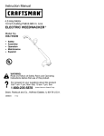
Instruction Manual
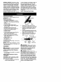
BRUSHCUTTER
ATTACHMENT
Model No,
358.792440
NOT DESIGNED
WITH ELECTRIC
FOR USE
POWERHEADS
• Safety
• Assembly
• Operation
• Maintenance
• Parts List
•
Espa_ol
DANGER:
Read and follow all Safety Rules and Operating
Instructions before first use of this product.
For answers to your questions about this product: Call 7
am-7 pm, Mon.-Sat., or 10 am-7 pm, Sun.
1-800-235-5878
Sears, Roebuck
530163625
1/29/03
and Co., Hoffman
<.o°,,
listed are Central Time)
Estates, IL 60179 U.S.A.
Warranty Statement
Identification of Symbols
Safety Rules
Assembly
Operation
Maintenance
2
2
2
5
10
14
Service & Adjustments
Storage
Parts List
Spanish
Parts and Ordering
14
15
16
17
Back Cover
FULL ONE YEAR WARRANTY ON CRAFTSMAN® BRUSHCUTTER ATTACHMENT
For one year from the date of purchase, when this Craftsman Brushcutter Attachment is maintained and lubricated according to the operating and maintenance
instructions in this manual, Sears will repair, free of charge, any defect in materials or workmanship.
This warranty excludes expendable parts that become worn during normal use.
If this Craftsman Brushcutter Attachment is used for commercial purposes, this warranty applies for only 90 days from the date of purchase. If this Craftsman Brushcutter Attachment is used for rental purposes, this warranty applies for only 30 days from
the date of purchase.
This warranty applies only while this product is in use in the United States.
WARRANTY SERVICE IS AVAILABLE BY RETURNING THE CRAFTSMAN BRUSHCUTTER ATTACHMENT TO THE NEAREST SEARS STORE OR SERVICE CENTER IN THE
UNITED STATES.
This warranty gives you specific legal rights, and you may also have other rights
which vary from state to state.
Sears, Roebuck and Co., I)/817 WA, Hoffman Estates, IL 60179
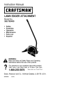
DANGER!
Read and understand the
instruction
manual before
using the brushcutter.
This brushcutter
can be dangerous! Careless or
improper use can cause
serious or even fatal injury,
[_
Always wear appropriate ear protection,
DWARNING:
When using gardening appliances, basic safety precautions should always be followed to reduce the risk of fire and serious injury.
Read and follow all instructions. Failure to do so can result in serious injury.
DANGER:
This power tool can be
dangerous! This unit can cause serious injury including amputation or
blindness to the operator and others.
The warnings and safety instructions
eye protection and head protection.
in this manual must be followed to provide reasonable safety and efficiency
in using the unit. The operator is responsible for following the warnings
and instructions in this manual and on
the unit. Read the entire instruction
manual before assembling and using
the unit[ Restrict the use of this unit to
persons who read, understand, and
follow the warnings and instructions in
this manual and on the unit. Never allow children to operate this unit.
all.WARNING:
Do not use trimmer
head as a fastening device for the
blade.
INSTRUCTION
MANUAL
_l_ DANGER:
vices.
SAFETY INFORMATION
ON THE UNIT
Never use flailing de-
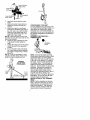
_1_ WARNING:
The blade continues
to spin after throttle is released or engine is turned off. The coasting blade
can throw objects or seriously cut you
if accidentally touched. Stop the blade
by contacting the left hand side of
coasting blade with material already
cut.
_l_ DANGER:
Blade can thrust violently away from material it does not
cut. Blade thrust can cause amputation of arms or legs. Keep people and
animals 50 feet (15 meters) away.
Stop coasting
blade by contact
with cut material.
_I_WARNING:
Blade/trimmer line
can throw objects violently. You can be
blinded or injured. Wear eye and leg
protection.
ALWAYS WEAR:
_
Eye
Protection
mt
• •
Leg
Guards
I_
_ ___._
_.,.,,_r
OPERATOR SAFETY
° Dress properly. Always wear safety
glasses or similar eye protection
when operating, or performing maintenance on your unit (safety glasses
are available). Eye protection should
be marked Z87.
* Always wear face or dust mask if operation is dusty.
* Always wear heavy, long pants, long
sleeves, boots, and gloves. Wearing
safety leg guards is recommended.
* Always wear foot protection. Do not
go barefoot or wear sandals. Stay
clear of spinning line/blade.
* Secure hair above shoulder length.
Secure or remove loose clothing and
jewelry or clothing with loosely hanging ties, straps, tassels, etc. They
can be caught in moving parts.
* Being fully covered also helps protect you from debris and pieces of
toxic plants thrown by spinning line/
blade.
* Stay Alert. Do not operate unit when
you are tired, ill, upset or under influence of alcohol, drugs, or medication. Watch what you are doing; use
common sense.
* Wear hearing protection.
Boots
_I_WARNING:
Hazard zone for
thrown objects. Blade/trimmer line can
throw objects violently. Others can be
blinded or injured. Keep people and
animals 50 feet (15 meters) away.
d Zone
3
• Never
startorruntheengine
insidea
closed
roomorbuilding.
Breathing
exhaust
fumescankill.
• Keephandles
freeofoilandfuel.
• Always
usethehandlebar
anda
properly adjusted shoulder strap
when using brushcutter attachment
(see ASSEMBLY).
UNIT/MAINTENANCE
SAFETY
_l_ WARNING:
Disconnect powerhead spark plug (or disconnect powerhead from power source) before performing maintenance.
• Look for and replace damaged or
loose parts before each use. Look
for and repair fuel leaks before use.
Keep unit in good working condition.
• Throw away blades that are bent,
warped, cracked, broken, or damaged in any other way. Replace trimmer head parts that are cracked,
chipped, broken, or damaged in any
other way before using the unit.
• Maintain the unit according to recommended procedures. Keep the blade
sharp. Never use flailing devices,
wire, rope, string, etc.
• Use only specified blade or trimmer
head; make sure it is properly installed and securely fastened.
• Never start engine with clutch shroud
removed. The clutch can fly off and
cause serious in ury.
• Be sure bade or tr mmer head stops
turning when engine idles.
• Make carburetor adjustments with the
lower end supported to prevent the
blade or trimmer line from contacting
any object. Hold the unit by hand; do
net use the shoulder strap for support.
• Keep others away when making carburetor adjustments.
• Use only recommended Craftsman
accessories and replacement parts.
• Have all maintenance and service
not explained in this manual performed by a Sears Service Center.
FUEL SAFETY
• Mix and pour fuel outdoors.
• Keep away from sparks or flames.
• Use a container approved for fuel.
• Do not smoke or allow smoking near
fuel or the unit or while using the unit.
• Avoid spilling fuel or oil. Wipe up all
fuel spills before starting engine.
• Move at least 10 feet (3 meters) away
from fueling site before starting engine.
• Stop engine and allow it to cool before removing fuel cap,
• Remove fuel cap slowly,
CUTTING SAFETY
_II'I_,wARNING: Inspect the area to be
cut before each use. Remove objects
(rocks, broken glass, nails, wire, string,
etc.) which can be thrown or become
entangled in the blade or trimmer line.
• Keep others including children, animals, bystanders, and helpers at
least 50 feet (15 meters) away. Stop
the engine immediately if you are approached.
• Always keep engine on the righthand side of your body.
• Hold the unit firmly with both hands.
• Keep firm footing and balance. Do
not overreach.
• Keep blade/trimmer head below
waist level.
• Do net raise powerhead engine above
your waist.
• Keep all parts of your body away
from spinning blade/line and muffler.
• Cut from your left to your right. CUtting on right side of shield will throw
debris away from the operator.
• Use only in daylight or good artificial
light.
• Use only for jobs explained in this
manual.
TRANSPORTING AND STORAGE
• Stop the powerhead engine before
carrying unit.
• Keep muffler away from your body.
• Allow engine to cool and secure unit
before storing or transporting it in a
vehicle.
• Empty the fuel tank before storing or
transporting the unit. Use up fuel left
in the carburetor by starting the engine and letting it run until it stops.
• Store unit and fuel in an area where
fuel vapors cannot reach sparks or
open flames from water heaters,
electric motors or switches, furnaces,
etc.
• Store unit so the blade or line limiter
blade on shield cannot accidentally
cause in ury.
• Store un t ndoors, out of reach of
children.
SPECIAL
NOTICE:
Exposure
tovibrationsthrough
prolonged
useofgasoline
powered
handtoolscouldcause
blood
vessel
ornerve
damage
inthefingers,
hands,
andointsofpeople
pronetocircuatondsorders
orabnorma
swerigs.
Prolonged
useincoldweather
hasbeen
linked
toblood
vessel
damage
inotherwisehealthy
people.
Ifsymptoms
occur
suchas numbness, pain, loss of
strength, change in skin color or texture,
CARTON CONTENTS
Check carton contents against the following list.
Model 358.792440
• Brushcutter Attachment
• Handlebar (with Clamp and Knob)
• Handlebar Clamp Base (with Spacer
Tabs)
• Shoulder Strap
• Upper Shoulder Strap Clamp
• Lower Shoulder Strap Clamp (with
Spacer Tabs)
Handlebar Clamp Screws (4)
Shoulder Strap Clamp Screws (2)
Large nut for installing blade
Cupped washer
Trimmer head
4-point weed blade (assembled on
brushcutter attachment)
• Wing nut (screwed onto shield)
• Metal shield (assembled on brushcutter attachment)
• Plastic shield
• Attachment Hanger
• Hex Wrench
• Container of line
Examine parts for damage. Do not use
damaged parts.
NOTE: If you need assistance or find
that parts are missing or damaged, call
1-800-235-5878.
or loss of feeling in the fingers, hands, or
joints, discontinue the use of this tool
and seek medical attention. An antivibration system does not guarantee the
avoidance of these problems. Users
who operate power tools on a continual
and regular basis must monitor closely
their physical condition and the condition
of this tool.
SAVE THESE INSTRUCTIONS
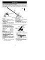
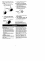
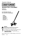
Coupler
LOOSEN
TIGHTEN
2,
3.
4.
5.
Knob
Remove the tube cap from the
brushcutter attachment (if present).
Position locking/release button of
attachment into guide recess of
coupler.
Push the attachment into the coupler until the locking/release button
snaps into the primary hole.
Before using the unit, tighten the
knob securely by turning clockwise.
Coupler
Primary Hole
\
/Guide Recess
Up!er
Tube
L°ckin _g/[_
Release Attachment
Button
all}WARNING:
Make sure the locking/release button is locked in the primary hole and the knob is securely
tightened before operating the unit.
HANDLEBAR ASSEMBLY
ASSEMBLY
=-&
all, WARNING:
If received assembled,
repeat all steps to ensure your unit is
properly assembled and all fasteners
are secure.
• A hex wrench (provided) is required
for assembly.
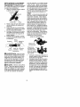
INSTALLING BRUSHCUTTER ATTACHMENT
DANGER:
RISK OF CUT To
avoid serious injury, the barrier portion of
the handlebar must be installed as
shown on the upper tube of the powerhead to provide a barrier between operator and the spinning blade. Attach
tube clamp above arrow on safety warning decal on the upper tube (powerhead
end of unit). Ensure handlebar is positioned on handlebar clamp between the
arrows on the handlebar decal.
CAUTION: When removing or installing attachments, place the unit on a
flat surface for stability.
1. Loosen the coupler by turning the
knob counterclockwise.
5
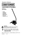
NOTE:Thetubeclamp
basehasfour
spacer
tabsattached.
These
tabsare
provided
toadapt
thisattachment
for
usewithpowerheads
thathavea 1"diameter
upper
tube(thetubeclamp
will
nottighten
downsecurely
onthe1"diameter
upper
tubewithout
usingthese
spacer
tabs).Thetabsmustbebroken
offcompletely
before
useandplaced
overthescrewholesontheclamp
base.
These
tabsarenotneeded
forpowerheads
witha7/8"uppertube.
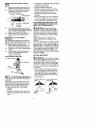
HANDLEBAR
CLAMP
BASE
Spacer
Tabs
Spacer
Tabs _
o °ai i° e rer ae
upper tube
1.
2.
_I
Place the tube clamp over the upper
tube above the arrow on the safety
decal.
Position the clamp base under the
upper tube and align the tube clamp
and clamp base screw holes (use
spacer tabs between tube clamp
and clamp base if necessary to secure clamp, i.e. for 1" diameter upper tube).
Handlebar
4.
Secure tube clamp by tightening
screws with the hex wrench.
5. Position the handlebar as shown,
ensuring the handlebar is positioned on the handlebar clamp between the two arrows on the handlebar decal.
6. Retighten handlebar byturning
clamp knob clockwise until handlebar is secure and stationary in
clamp (clamp knob cannot be
overtightened).
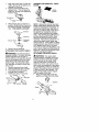
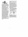
SHOULDER STRAP ASSEMBLY
_1_ WARNING:
Proper shoulder
strap and handlebar adjustments must
be made with the engine completely
stopped before using unit. The shoulder strap clamp must be installed as
shown above the handlebar on the upper tube (powerhead end of unit).
NOTE: The lower shoulder strap clamp
has two spacer tabs attached. These
tabs are provided to adapt this attachment for use with powerheads that have
a 1" diameter upper tube (the shoulder
strap clamp will not tighten down securely on the 1" diameter upper tube
without using these spacer tabs). The
tabs must be broken off completely before use and placed over the screw
holes on the lower shoulder strap clamp.
These tabs are not needed for powerheads with a 7/8" upper tube.
LOWER SHOULDER STRAP
CLAMP
Spacer Tabs_'r
_
POWERHEAD
END
Handlebar Clamp
between arrows on
handlebar decal
.,dC_L.4--_ _- Spacer Tabs
I1_-_
positioned for use
on 1" diameter
Clam
Knob
upper tube
1,
Clamp
Screws
2.
Arrow on
Safety Decal
ATTACHMENT
3.
END
Insert four screws
holes.
into the screw
Place the upper shoulder strap
clamp over the upper tube above
the handlebar.
Position the lower shoulder strap
clamp under the upper tube and
align the upper and lower clamp
screw holes (use spacer tabs between upper and lower clamps if
necessary to secure clamp, i.e. for
1" diameter upper tube).
!Clamp
POWERHEAD
END
30 inches
Lower Shoulde
Strap Clamp
I
•
o
ATTACHMENT
END
3.
Insert two screws into the screw
holes.
4. Secure shoulder strap clamp by
tightening screws with the hex
wrench.
5. Insert your right arm and head
through the shoulder strap and allow it to rest on your left shoulder.
Make sure the danger sign is on
your back and the hook is to the
right side of your waist.
NOTE: A one-half twist is built in the
shoulder strap to allow the strap to rest
flat on the shoulder.
6. Adjust the strap, allowing the book
to be about 6 inches below the
waist.
7. Fasten the strap hook to the clamp
and lift the tool to the operating
position.
8. Try on shoulder strap and adjust
for fit and balance before starting
the engine or beginning a cutting
operation.
NOTE: It may be necessary to relocate the shoulder strap clamp on the
shaft for proper balancing of unit.
HARNESS
ADJUSTMENT
FOR BALANCE
6 inches
below
waist
4 - 12
inches
above
ground
CONFIGURING YOUR UNIT
You can configure your unit using a trimmer head for grass and light weeds, or a
weed blade for cutting grass, weeds,
and brush up to 1/2 inch in diameter. To
assemble your unit, go to the section for
the desired configuration and follow the
instructions.
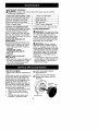
ASSEMBLY INFORMATION TRIMMER HEAD
TRIMMER
HEAD
NOTE: Remove the blade and metal
shield before attaching the plastic shield
and trimmer head. To remove blade,
align hole in the dust cup with the hole
in the side of the gearbox by rotating
the blade. Insert a small screwdriver
into aligned holes. This will keep the
shaft from turning while loosening the
blade nut. Remove blade nut by turning
clockwise. Remove the screwdriver.
Remove both washers and blade. To
remove metal shield, loosen and remove the four mounting screws. See ATTACHING THE METALSHIELD and
INSTALLATIONOF THE METAL BLADE for
illustrations. Be sure to store all parts
and instructions for future use.
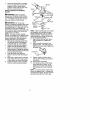
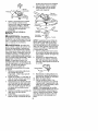
INSTALLATION OF THE TRIMMER
HEAD
NOTE: Before installing the trimmer
head, make sure the dust cup and retaining washer are positioned on the
shaft of the gearbox, The retaining
washer must be positioned with the
raised section toward the gearbox,
1, Alignholeinthedustcupwiththe
holeinthesideofthegearbox
by
rotating
thedustcup.
2, Insertasmallscrewdriver
into
aligned
holes,Thiswillkeepthe
shaftfromturning
whiletightening
trimmer
head,
3,
While holding the screwdriver in
position, thread trimmer head onto
the shaft by turning counterclockwise. Only tighten hand tightt
Gearbox
Dust Cup
Tnmmer Head
_
Retaining
Washer
J
4, Removethe
screwddver,
ATTACHING THE PLASTIC SHIELD
_WARNING:
The shield must be
properly installed. The shield provides
partial protection from the risk of
thrown ob ects to the operator and others and sequppedwtha
ne mter
blade which cuts excess line to the
proper length. The line limiter blade
(on underside of shield) is sharp and
can cut you.
1. Remove wing nut from shield.
2. Insert bracket into slot on shield.
3. Pivot shield until bolt passes
through hole in bracket.
4. Tighten the wing nut securely.
Slot Bracket \
Shield _*_
&:o_
ASSEMBLY INFORMATION
BLADE
_lb
- WEED
WEED
BLADE
NOTE: Remove the trimmer head and
plastic shield before attaching the metal
shield and installing the weed blade. To
remove the trimmer head, align hole in
the dust cup with the hole in the side of
the gearbox by rotating the dust cup.
Insert a small screwdriver into aligned
holes. This will keep the shaft from turning while loosening the trimmer head.
Remove the trimmer head by turning
clockwise. Remove the screwdriver. To
remove the plastic shield, loosen and
remove wing nut. Pivot shield to release
bracket from slot. See INSTALLATIONOF
THE TRIMMER HEAD and ATTACHING
THE PLASTICSHIELD for illustrations. Be
sure to store all parts and instructions for
future use. Never use the trimmer head
with the metal blade installed.
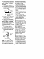
ATTACHING THE METAL SHIELD
_I_WARNING:
The metal shield
must be properly installed on the tool
anytime the tool is used with a blade.
The forward tip of the metal shield
helps to reduce the occurrence of
blade thrust which can cause serious
injury such as amputation to the operator or bystanders. Failure to install the
shield in the position shown can result
in serious injury to the operator. The
length of the shield must be aligned
with the length of the tube.
1. Place the metal shield under the
gearbox, and align the screw holes.
W_iingNut
Gearbox
_Gearbo_
Shield
2, Insertandthread
the4 mounting
screws
through
theholesofthe
_earbox
andthemetalshield.
ightenevenly
andsecurely
with
thehexwrench
provided,
INSTALLATION
BLADE
OF THE METAL
Gearbox
Shield
\
_l_ WARNING:
Wear protective
gloves when handling or performing
maintenance on the blade to avoid injury. The blade is sharp and can cut
you even when it is not moving.
_I_WARNING:
Do not use any
blades, or fastening hardware other than
the washers and nuts shown in the following illustrations. These parts must be
provided by Sears and installed as
shown below. Failure to use proper parts
can cause the blade to fly off and seriously hurt you or others.
NOTE: The dust cup and retaining
washer are located on the gearbox shaft
and not in the parts bag. All other fasteners mentioned in the following assembly steps are in the parts bag.
1. Remove the retaining washer from
the threaded shaft of the gearbox.
Leave the dust cup on the shaft.
2. Install the blade and the retaining
washer over the threaded shaft.
3. Make sure the raised part of the retaining washer is facing the gearbox
and the raised area fits into the hole
in the center of the blade.
4. Slide the blade and retaining
washer onto the shaft of the gearbox.
5. Place the cupped washer onto the
shaft. Make sure the cupped side
of the washer is toward the blade.
6. Install the blade nut by threading
onto the shaft counterclockwise.
Dust Cu
Threaded
Shaft
Blade
Retaining
Washer ---_
Cupped__
Washer
_",_-_
Nut
NOTE: Make sure all parts are in place
as illustrated, and the blade is sandwiched between the dust cup and the
retaining washer. There should be no
space between the blade and the dust
cup or the retaining washer.
7. Align hole in dust cup with hole in
side of gearbox by rotating the
blade.
8. Insert a small screwdriver into
aligned holes. This will keep the
shaft from turning while tightening
the blade nut.
9.
Tighten blade nut firmly with a
wrench while holding screwdriver
in position.
10. Remove the screwdriver.
11. Turn blade by hand. If the blade
binds against the shield, or appears to be uneven, the blade is
not centered, and you must reinstall.
NOTE: To remove blade, insert screwdriver into aligned holes. Unthread the
nut and remove parts. Be sure to store
parts and instructions for future use.
KNOW YOUR BRUSHCUTTER
ATTACHMENT
READ THIS INSTRUCTION MANUAL AND SAFETY RULES BEFORE OPERATING YOUR
BRUSHCUTTER ATTACHMENT. Compare the illustrations with your unit to familiarize
yourself with the location of various controls and adjustments, Save this manual for
future reference,
be
_T_
Hanger
Trimmer Shield
Blade Shield
BLADE
The BLADE is designed for cutting
grass, weeds, and brush up to 1/2 inch
m diameter.
TRIMMER HEAD
The TRIMMER HEAD holds cutting line
and is designed for cutting grass and
light weeds.
OPERATING THE COUPLER
Your powerhead is equipped with a
coupler which enables optional attachments to be installed. The optional attachments are:
Edger ...............
358.792400
Cultivator ............
358.792410
Blower ..............
358.792421
WARNING:
Always disconnect
powerhead spark plug before removing or installing attachments.
_'-_
BLADE SHIELD
The BLADE SHIELD provides protection
from the spinning blade.
TRIMMER SHIELD
The TRIMMER SHIELD provides protection from the spinning trimmer head.
Upper Tube
Coupler
Lower
\
LOOSEN
Attachment
TIGHTEN
2.
REMOVING BRUSHCUTTER AT*
TACHMENT (OR OTHER OPTIONAL
ATTACHMENTS)
CAUTION: When removing or installing attachments, place the powerhead
and attachment on a flat surface for
stability.
Loosen the coupler by turning the
knob counterclockwise.
10
Knob
Press and hold the locking/release
button.
Lower Attachment
3.
1.
Blade
UpperTube
While securely holding the upper
tube, pull the attachment straight
out of the coupler.
INSTALLING
OPTIONAL
ATTACH*
MENT
1. Remove the tube cap from the attachment (if present)and discard.
2. Position locking/release button of
attachment into guide recess of
upper tube coupler.
Coupler Primary Hole
Upper
Tube
Locking/
Release
Button
Attachment
3.
Push the attachment into the coupler until the locking/release button
snaps into the primary hole.
4. Before using the unit, tighten the
knob securely by turning clockwise.
INSTALLING ATTACHMENT
HANGER
An attachment hanger is provided for
storage when attachment is not in use.
To install hanger on attachment:
1. Remove the tube cap from the attachment (if present) and discard.
2. Press and hold the locking/release
button.
3. Push hanger onto the attachment
until the locking/release button
snaps into the hole.
OPERATING POSITION
ALWAYS WEAR:
Heavy,
_
Protection
Long Pants
Boots _,.
NOTE: This brushcutter attachment is
not designed for use with electric powerheads.
When operating unit with brushcutter
attachment, clip shoulder strap onto
upper shoulder strap clamp, stand as
shown and check for the following:
• Wear eye protection and heavy
clothing.
• Keep arms extended with right hand
holding the trigger handle of powerhead.
• Keep left arm extended with left hand
holding the handlebar.
• Keep unit below waist level.
• Shoulder strap pad should be centered on your left shoulder and danger sign centered on your back.
• Maintain full weight of tool on left
shoulder.
• Without bending over, keep the blade
near and parallel to the ground and
not crowded into material being cut.
OPERATING INSTRUCTIONS FOR
USE OF BRUSHCUTTER ATTACH*
MENT WITH TRIMMER HEAD
_l_ WARNING:
Always wear eye
protection. Never lean over the trimmer head. Rocks or debris can ricochet or be thrown into eyes and face
and cause blindness or other serious
injury.
Before trimming, bring engine to a
speed sufficient to cut material to be
trimmed.
De net run the engine at a higher speed
than necessary. The cutting line will cut
efficiently when the engine _srun at less
than full throttle. At lower speeds, there
is less engine noise and vibration. Always release the throttle trigger and
allow the engine to return to idle speed
when not cutting.
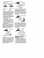
CUTTING METHODS
_I_WARNING:
Use minimum speed
and do not crowd the line when cutting
around hard objects (rock, gravel,
fence posts, etc.), which can damage
the trimmer head, become entangled
in the line, or be thrown causing a serious hazard.
• The tip of the line does the cutting.
You will achieve the best performance and minimum line wear by not
crowding the line into the cutting
area. The right and wrong ways are
shown below.
Tip of line does the
Right
11
Line crowded into
i Wrong
* The
line will easily remove grass and
weeds from around walls, fences,
trees and flower beds, but it also can
cut the tender bark of trees or shrubs
and scar fences.
* For trimming or scalping, use less
than full throttle to increase line life
and decrease head wear, especially:
• During light duty cutting.
• Near objects around which the line
can wrap such as small posts,
trees or fence wire.
* For mowing or sweeping, use full
throttle for a good clean job.
TRIMMING - Hold the bottom of the
trimmer head about 3 inches (8 cm)
above the ground and at an angle. Allow
only the tip of the line to make contact.
Do not force trimmer line into work
area.
Trimming
SCALPING - The scalping technique
removes unwanted vegetation down to
the ground. Hold the bottom of the
trimmer head about 3 inches (8 cm)
above the ground and at an angle. Allow the tip of the line to strike the
ground around trees, posts, monuments, etc. This technique increases
line wear.
Scalping
MOWING - Your trimmer is ideal for
mowing in places conventional lawn
mowers cannot reach. In the mowing
position, keep the line parallel to the
ground. Avoid pressing the head into
the ground as this can scalp the
ground and damage the tool.
Mowing
SWEEPING - The fanning action of
the rotating line can be used to blow
away loose debris from an area. Keep
the line parallel to and above the area
surface and swing the tool from side to
side.
/._Sweeping
_'8
r
OPERATING INSTRUCTIONS FOR
USE OF BRUSHCUTTER ATTACH*
MENT WITH WEED BLADE
* Blade Thrust is a reaction that only
occurs when using a bladed unit. This
reaction can cause serious injury such
as amputation. Carefully study this
section. It is important that you understand what causes blade thrust, how
you can reduce the chance of its occurring, and how you can remain in
control of unit if blade thrust occurs.
* WHAT CAUSES BLADE THRUST Blade Thrust can occur when spinning blade contacts an object that it
does not cut. This contact causes
blade to stop for an instant and then
suddenly move or "thrust" away from
object that was hit. The "thrusting" reaction can be violent enough to cause
operator to be propelled in any direction and lose control of unit. The uncontrolled unit can cause serious injury
if blade contacts operator or others.
* WHEN BLADE THRUST OCCURS
- Blade Thrust can occur without
warning if the blade snags, stalls, or
binds. This is more likely to occur in
areas where it is difficult to see the
material being cut. By using the unit
properly, the occurrence of blade
thrust will be reduced and the operator will be less likely to lose control.
12
• Cutonlygrass,
weeds,
andwoody
brush
upto1/2inchindiameter
with
weedblade.
Donotletbladecontact
material
itcannot
cutsuchasstumps,
rocks,
fences,
metal,
etc.,orclusters
ofhard,woody
brush
witha diameter
greater
than1/2inch.
• Useasharpblade.Adullbladeis
morelikelytosnagandthrust.
• Cutonlyatfullthrottle.
Thebladewill
havemaximum
cuttingpowerandis
lesslikelytobindorstall.
• "Feed"
thebladedeliberately
andnot
toorapidly.
Thebladecanthrust
awayif itisfedtoorapidly.
• Cutonlyfromyourlefttoyourright.
Cutting
onrightsideoftheshieldwill
throwdebris away from the operator.
• Use the shoulder strap and keep a
firm grip on the unit with both hands.
A properly adjusted shoulder strap
will support the weight of the unit,
freeing your arms and hands to control and guide the cutting motion.
• Keep feet comfortably spread apart
and braced for a possible sudden,
rapid thrust of unit. Do not overreach.
Keep firm footing and balance.
• Keep blade below waist level. It will
be easier to maintain control of unit.
• Do not raise the engine above your
waist as the blade can come dangerously close to your body.
• Do not swing the unit with such force
that you are in danger of losing your
balance.
Bring the powerhead engine to cutting
speed before entering the material to
be cut.
If the blade does not turn when you
squeeze the throttle trigger of the powerhead, make sure the attachment is
fully inserted into the coupler.
Always release the throttle trigger and
allow powerhead engine to return to
idle speed when not cutting. The blade
should not turn while the engine is running at idle. If the blade turns at idle,
do not use your unit. Refer to the CARBURETOR ADJUSTMENT section of the
powerhead manual or contact your
Sears Service Center.
• Maintain good firm footing while using the unit. Do this by planting feet
firmly in a comfortable apart position.
• Cut while swinging the upper part of
your body from left to right.
• As you move forward to the next
area to cut, be sure to maintain your
balance, and footing.
RECOMMENDED CUTTING POSITION
Cut using the 2
o'clock to 4 o'clock
position of the
blade
_2
_}
4 o'clock
o'clock
_l_ WARNING:
The operator or others must not try to clear away cut material with the engine running or the
blade turning to avoid serious injury.
Stop engine and blade before removing materials wrapped around blade or
tube.
13
MAINTENANCE SCHEDULE
_WARNING:
Always stop unit and disconnect
performing maintenance.
CARE AND MAINTENANCE
TASK
spark plug wire before
WHEN TO PERFORM
Check for loose fasteners and parts
Before each use
Check for damaged or worn parts
Inspect and clean unit and decals
Check or replace blade
Before each use
After each use
Every 5 hours of operation
GENERAL RECOMMENDATIONS
The warranty on this attachment does
not cover items that have been subjected to operator abuse or negligence. To receive full value from the
warranty, the operator must maintain
the brushcutter attachment as instructed in this manual.
CHECK FOR DAMAGED OR
WORN PARTS
Contact Sears Service Center for replacement of damaged or worn parts.
• Blade Shield - Discontinue use of
brushcutter attachment if shield is
damaged.
• CHECK FOR LOOSE
FASTENERS AND PARTS
• Blade nut
• Fasteners
INSPECT AND CLEAN UNIT
AND DECALS
• After each use, inspect complete unit
for loose or damaged parts. Clean
the unit and decals using a damp
cloth with a mild detergent.
LINE REPLACEMENT
• Always use Craftsman replacement
line.
Choose the line size best suited for the
job at hand. Red line is designed for
cutting grass and small weeds. The
black colored line is designed for cutting larger weeds and light brush.
NOTE: Before inserting new line into
the holes in the cutting head, identify
the proper holes. Follow directions as
shown on the line glide plate.
1. Remove the old line and line glide
plate from the cutting head.
2. Clean entire surface of cutting
head.
3. Reinstall line glide plate (see illustration). Align arrow with:
• Wipe off unit with a clean dry cloth.
BLADE MAINTENANCE
_WARNING:
The blade will continue to spin after the engine stops or after the throttle trigger has been released. To avoid serious injury, make
sure the blade has stopped coasting
and disconnect the spark plug before
performing work on the blade.
WARNING:
Always replace a
blade that is bent, warped, cracked,
broken, or damaged in any other way.
Never attempt to straighten and reuse
a damaged blade. Use only specified
replacement blade. Wear protective
gloves when handling or performing
maintenance on the blade to help
avoid injury.
• Check blade for flatness periodically.
Lay the blade on a flat surface to inspect for flatness. Throw away a
blade that is not flat.
when using medium (red) or
(_) large (black) line
when using lines with diameter
(_) smaller than medium (red) line
(optional)
Line glide
Trimmer head
14
Arrow
NOTE:Lineglideplatemustbereinstalled
incutting
headbefore
inserting
newline.
4. Insertbothendsofyourline
through
theproperholesinthe
sideofthecuttinghead.
!
5,
Pull the line and make sure the
line is against the hub and extended full through the positioning
tunnels.
Line against
6.
Correctly installed line will be the
same length on both ends.
REPLACING THE CUTTING HEAD
1. Align hole in the dust cup with the
hole in the side of the gearbox by
rotating the dust cup.
2. Insert a small screwdriver into
aligned holes. This will keep the
shaft from turning while removing
and installing trimmer head.
3. While holding the screwdriver
in
position, remove trimmer head by
turning clockwise.
4.
Thread replacement trimmer head
onto the shaft by turning counterclockwise. Only tighten hand tight!
5. Remove the screwdriver.
Tunnel \
BLADE REPLACEMENT
Refer to the ASSEMBLY section for
blade replacement instructions and illustrations.
WARNING:
Perform the following
steps after each use:
• Allow attachment and gearbox to
cool before storing or transporting.
• Store attachment with blade shield in
place. Position attachment so that
any sharp object cannot accidentally
cause injury.
• Store the attachment in a dry, well
ventilated area out of the reach of
children.
SEASONAL STORAGE
Prepare attachment for storage at end
of season or if it will not be used for 30
days or more.
If your brushcutter attachment is to be
stored for a period of time:
• Clean the entire attachment.
• Inspect the blade shield area and
clean any dirt, grass, leaves, or debris that has collected. Inspect the
blade and blade shield; replace a
blade that is bent, warped, cracked,
broken or damaged in any other way.
• Lightly oil external metal surfaces.
• Apply a coating of oil to the entire
surface of the blade; wrap it in heavy
paper or cloth.
• Check entire attachment for loose
screws or nuts. Replace any damaged, worn or broken parts.
• At the beginning of the next season,
use only fresh fuel having the proper
gasoline to oil ratio.
15
Declaraci6n de Garantia
Identificaci6n de Simbolos
Reglas de Seguridad
Montaje
Uso
17
17
17
20
26
Mantenimiento
Servicio y Ajustes
Almacenaje
Lista de Piezas
Repuesto y Encargos
30
31
32
16
Contratapa
GARANTIA COMPLETO DE UN A_IO PARA LA CORTADORA DE MALEZAS
ACCESORIO CRAFTSMAN ®
Durante un a_o completo, a partir de la fecha de compra, siempre que se haga el
mantenimiento, la lubricaci6n y los ajustes a esta Cortadora de Malezas Acceso*
rio Craftsman segQn las instrucciones de uso y mantenimiento en el manual,
Sears reparar_ cualquier defecto de materiales o de mano de obra gratuitamente.
Esta garantia excluye las partes que se gastan durante el uso normal.
Si se usa esta Cortadora de Malezas Accesorio Craftsman con fines comerciales,
esta garanfia tendr_ validez por s61a 90 dias a partir de la fecha de compra. Si se
usa esta Cortadora de Malezas Accesorio Craftsman con fines de alquiler, esta
garantia tendr_ validez s61amente por 30 ctias a partir de la fecha de compra.
Esta garanfia tendr_ validez Qnicamente mientras se use este producto dentro de
los Estados Unidos.
SE OBTENDRA SERVlCIO BAJO GARANTIA DEVOLVlENDO LA CORTADORA DE MALEZAS ACCESORIO CRAFTSMAN AL TIENDA CE SEARS O CENTRO DE SERVlClO
SEARS MAS CERCANO EN LOS ESTADOS UNIDOS.
Esta garantia confiere derechos legales especificos al propietario, que tal vez
tenga asimismo otros derechos que varian entre estados.
Sears, Roebuck and Co., 13/817 WA Hoffman Estates, IL 60179
PELIGRO:
iEsta
cortadora
Ir_--_
demalezas puede serpeligrosa!
esta
causar
El usoherramienta
descuidado puede
o indebido
de i_LJJ_
graves o a_n heridas fatales!
Use siempre la proteccion de oidos apropiada,
ojos y la protecci6n de la cabeza.
ADVERTENCIA:
AI usar cualqui*
er herramienta de fuerza de jardineria,
deber_n observarse precauciones b_sicas de seguirdad en todo momento
para reducir el riesgo de incendio y
graves heridas. Lea y cumpla con todas
]as instrucciones. Su incumplimiento
puede ocasionar lesiones graves.
PELIGRO:
i Esta herramienta motorizada puede set peligrosa! Puede
ocasionar lesiones graves, incluso la
Lea
y comprenda
el
manual
de
instruccortadora
de malezas.
clones antes
de user la
la protecci6n de
amputaci6n o la ceguera, tanto al operador como a otras personas. Las advertencias e instrucciones de seguridad
contenidas en este manual deben cumplirse en todo momento para garantizar
un nivel de seguridad y efectividad razonable durante la utilizaci6n del aparato. El operador es responsable del
cumplimiento de las advertencias e
instrucciones indicadas en este manual
yen el aparato. Antes de ensamblar y
utilizar el aparato, lea integramente el
17
manual
deinstrucciones.
Limite
eluso
deesteaparato
a personas
quepreviamente
hayan
leidoycomprendido,
y
posteriormente
cumplan,
lasadvertenciase instrucciones
indicadas
eneste
manual
yenelaparato.
Nunca
permita
queesteaparato
seautilizado
porniSos.
MANUAL DE
INSTRUCClONES
_1_ PELIGRO:
desgranadores.
tNFORMACION
DE
SEGURIDAD
DEL
APARATO
e peligro
_d
Zona
DADVERTENCIA:
No utilice el cabezal de corte como dispositivo de sujeci6n de la cuchilla,
Nunca usedispositivos
_1_ PELIGRO:
La cuchilla puede rebotar violentamente en materiales que no
puede cortar, Los rebotes de la cuchilla
pueden causar la amputaci6n de brazos
o piernas. Mantenga a personas y anima]es lejos de la herramienta (15 metros).
4E_ADVERTENCIA:
La cuchilla sigue girando incluso despu6s de soltar
el acelerador o de apagar el motor, Incluso cuando est_ girando libremente,
]a cuchilla puede despedir objetos o
causar cortes profundos si se toca accidentalmente, Detenga la cuchilla poniendo en contacto el lado izquierdo
de la misma con material ya cortado,
Para detener la cuchiIla cuando gire libremente, p6ngala en
contacto con material
•
._._
_'_
_J_'_
previamen_enmot_
,_ADVERTENCIA:
La cuchilla/
]inea de corte puede despedir objetos
violentamente. Esto puede ocasionarle
ceguera o lesiones. Prot6jase los ojos
y las piernas.
UTILICE SIEM
Protecci6n
ocular
1
Perneras
Bo,as
ADVERTENClA:
Zona de peligro
de objetos despedidos. La cuchina/linea
de corte puede despedir objetos violentamente, Esto puede ocasionar ceguera
o lesiones a otros, Mantenga a personas y animales lejos de la herramienta
15 metros (50 pies).
SEGURIDAD DEL OPERADOR
• Vistase apropiadamente.
Siempre
use anteo os de seguridad o similar
protecc 6n para os o os cuando use
o d6 mantenimiento a este aparato
(anteojos de seguridad est_n disponibles). La protecci6n para los ojos
debe ser marcada con Z87.
• Siempre utilize mascarilla para la
cara o mascarilla a prueba de polvo
si se va a trabajar en condiciones
donde hay polvo.
• Siempre utilize pantalones pesados
y largos, mangas largas, botas y
guantes. Se recomienda el uso de
pantorrilleras de seguridad.
• Siempre utilize protecci6n para los
pies. No trabaje descalzo ni en
sandalias. Evite la cuchilla/linea de
corte girante.
18
• Mantenga
elcabello
porencima
de
• Realice los ajustes del carburador
loshombros,
at_ndolo
paratalefecto con la parte inferior apoyada en alto
siesnecesario.
Nouseropasuelta
ni
para impedir que la cuchilla entren
ropaconcorbatas,
tiras,borlas,
etc.
en contacto con alg6n objeto. Sujete
quecuelgan
libremente.
Pueden
enre- el aparato con las manos, sin utilizar
darse
enlaspiezas
enmovimiento. la correa al hombro.
• Siest_completament
tapado,
estar_ • Cuando realice ajustes en el carbum_sprotegido
delosescombros
y
rador, mantenga alejadas del lugar a
pedazos
deplantas
t6xicos
arrojaotras personas.
• Utilice exclusivamente los accesorios
dosporlacuchilla
girante.
• Mant6ngase
alerta.Nohagausodel y recambios recomendados por
aparato
estando
cansado,
enfermo, Craftsman.
• Confie todas las tareas de mantenitrastornado
o bajolainfluencia
del
alcohol,
dedrogas
o deremedios.
miento y reparaci6n no explicadas
VigilebienIoqueest_haciendo;
use en este manual a su Centro de
delsentido
comen.
Servicio de Sears.
• Useprotecci6n
deoidos.
SEGURIDAD CON EL COMBUS*
• Nunca
pongaelaparato
enmarcha TIBLE
niIodejeenmarcha
dentrodeun
y vierta el combustible en
recinto
cerrado.
Respirar
losvapores • Mezcle
exteriores.
del combustible Io puede matar.
• Mantenga las manijas libres de
aceite y de combustible.
• Utilice siempre el mango y una
correa para hombro correctamente
ajustada al usar la cortadora de
malezas accesorio (yea MONTAJE).
MANTENIMIENTO Y SEGURIDAD
DEL APARATO
_l_ ADVERTENCIA:
Desconecte la
bujia (o desconecte aparato de la corriente el6ctrica) antes de hacer cualquier mantenimiento.
• Antes de cada uso, busque las piezas
daSadas o sueltas y sustiteyalas. Antes de cada uso, busque posibles fugas de combustible y, en su caso, rep_relas. Mantenga el aparato en buen
estado de funcionamiento.
• Deseche la cuchillas dobladas, dentadas, partidas, rotas o deterioradas
de algen modo. Antes de utilizar la
unidad, sustituya las piezas del cabezal de corte que est6n partidas,
rotas o deterioradas de alg_n modo.
• Realice el mantenimiento del aparato
siguiendo los procedimientos recomendados. Mantenga ]a cuchilla afilada. Nunca utilice dispositivos desgranadores, cable, cuerda, alambre, etc.
• Utilice exclusivamente la cuchilla o el
cabezal de corte especificado y aseig6rese de que est6 correctamente
nstalado y firmemente sujeto.
• Nunca ponga en marcha el motor
con el cubierta del embrague desmontado. El embrague podria desprenderse y causar graves lesiones.
• Aseg_rese de que el cuchilla o el
cabezal de corte se detiene al pasar
el motor al ralentL
• Mantenga el combustible alejado de
chispas y llamas.
• Utilice recipientes homologados para
el uso de combustibles.
• Impida que se fume cerca del combustible o del aparato, tanto si 6ste se
encuentra parado o se est_ utilizando.
• Antes de porter en marcha el motor,
limpie todo posible resto de combustible derramado.
• Antes de poner en marcha el motor,
al6jese como minimo 3 metros del lugar de repostaje.
• Antes de quitar el tap6n de combustible, detenga el motor y d6jelo enfriar.
• Remueva la tapa del tanque de combustible lentamente.
SEGURIDAD AL CORTAR
ADVERTENCIA:
Antes de cada
uso, inspeccione la zona de trabajo.
Retire todos los objetos (rocas, cristales rotos, clavos, cables, hilos, etc.)
que puedan ser despedidos o quedar
enredados en la cuchilla.
• Mantenga alejados del lugar de trabajo (15 metros) a otras personas,
ya sean niSos, acompaSantes o ayudantes, y a animales. Detenga el
motor tan pronto como alguien se le
aproxime.
• Mantenga siempre el motor junto al
lado derecho de su cuerpo.
• Sujete firmemente la unidad con ambas manos.
• Pise con seguridad y mantenga el
equilibrio en todo momento. No estire el cuerpo en exceso.
• Mantenga la cuchilla por debajo de
la cintura.
• No levante el cabeza de motor por encima de su cintura.
19
* Mantenga todas las partes de su
cuerpo alejadas de la cuchilla y del
silenciador.
* Corte siempre de izquierda a derecha.
Si se corta con la linea del lado derecho del protector, los escombros volar_n en sentido opuesto al usuario.
* Use el aparato 0nicamente de dia o
en luz artificial fuerte.
* Utilice el aparato solamente para las
tareas explicadas en este manual.
TRANSPORTE Y ALMACENAMIENTO
* Antes de proceder a su transporte,
detenga el cabeza de motor.
* Mantenga el silenciador alejado del
cuerpo.
* Antes de almacenar o transportar el
aparato en un vehiculo, deje enfriar
el motor y sujete bien el aparato.
* Antes de guardar o transportar el
aparato, vacie el dep6sito de combustible. Arranque el motor y d6jelo
en marcha hasta que se detenga
con el fin de agotar el combustible
que pueda quedar en el carburador.
* Guarde el aparato y el combustible
en un lugar donde los vapores emanados del combustible no puedan
entrar en contacto con chispas ni llamas procedentes de calentadores
de agua, motores o interruptores
el6ctricos, hornos, etc.
* Guarde el aparato de modo que la
cuchilla no puedan ocasionar lesiones accidentalmente.
* Guarde el aparato dentro, fuera del
alcance de los niSos.
NOTA ESPECIAL: El estar expuesto
alas vibraciones a trav6s del uso proIongado de herramientas de fuerza a
gasolina puede cuasar daSos a los vasos sanguineos o a los nervios de los
dedos, las manos y las coyunturas en
aquellas personas que tienen propensidad a los trastomoe de la circulaci6n
o alas hinchazones anormalee. El uso
prolongado en tiempo frJo ha sido asociado con daSos a los vasos snaguineos de personas que por otra
parte se encuentran en perfecto estado de salud. Si ocurren eintomas tales
como el entumecimiento, el dolor, la
falta de fuerza, los cambios en el color
o la textura de la piel o falta de sentido
en los dedos, las manos o las coyunturas, deje de usar esta m_quina inmediatamente y procure atenci6n
m6dica. Los sistemas de anti-vibraci6n no garantizan que se eviten tales
problemes. Los usuarios que hacen
uso continuo y prolongando de las
herramientas de fuerza deben fiscalizar atentamente su estado fisico y el
estado del aparato.
GUARDE ESTAS INSTRUCClONES
CONTENIDO DE LA CAJA
Use la siguiente lista para verificar que
todas la piezas hayan sido incluido:
Model 358.792440
* Cortadora de Malezas Accesorio
* Mango (con Abrazadara y Perilla)
* Base de Abrazadera (con Tabulaciones
del Espaciador)
* Correa al Hombro
* Abrazadera Superior del Correa de
Hombro
* Abrazadera
Inferior del Correa de
Hombro (con Tabulaciones del Espaciador)
. Tornillos de Abrazadera del Mango (4)
. Tornillos de Abrazadera del Correa de
Hombro (2)
. Tuerca Larga para installar la Cuchilla
. Arandela Abombada
* Cabezal de Corte
* Cuchilla con 4 puntas para el corte de
malezas (ensamblado en el aparato)
• Tuerca Mariposa (atorninada en la protector)
* Protector Met_lica (ensamblado en el
aparato)
* Protector Pl_stica
* Suspensor del Accesorio
* Llave Hexagonal
* Recipiente de linea
AsegDrese de que ninguna pieza est6
da_ada. No utilice piezas daSadas.
NOTA: Si necesita ayuda o detecta que
alguna pieza falta o est_ daSada, Ilame
al 1-800-235-5878.
MONTAJE
_I_ADVERTENClA:
Si recibe el
aparato ya armado, repita todos los pasos para asegurarse de que el aparato
est6 correctamente ensamblado y todas
las sujeciones firmes.
* Un Ilave hexagonale (incluidas) se
requiere para el montaje.
2O
INSTALACION
DE LA ACCESORIO
DEL CORTADORA DE MALEZAS
PRECAUCION: AI instalar las accesorio, ponga el aparato en una superficie plana para estabilidad.
1. Afloje el acoplador dando vuelta a
]a perilla a la izquierda.
Acoplador
AFLOJE
Perilla
2,
3.
4.
5,
Retire la tapa de tubo del accesorio del cortadora de malezas (si
presente).
oloque el bot6n de conexi6n/desconexi6n del accesorio en el agujero de la guia del acoplador.
Empuje el accesorio en el acoplador hasta que el bot6n de conexi6n/desconexi6n se encaje en el
primer agujero.
Antes de usar el aparato, apriete
]a perilla firmemente dando vuelta
a la derecha.
Primer
Acoplador\
PgLJe_ iAag_eriOa
de
Tubo
Superior
Bot6n de Accesorio
Conexi6n/ inferior
Desconexion
ADVERTENCIA:
Antes de operar esta aparato, aseg0rese de que el
bot6n de conexi6n/desconexi6n
est6
asegurado en el primer agujero y la
perilla est6 bien ajustada. Todos los
accesorios hart sido dise5ados para
ser utilizados en el primer agujero.
INSTALLATION DEL MANGO
entre el operador y la cuchilla durante
el giro de 6sta. ]nstale la abrazadera
del tubo sobre la flecha de la etiqueta
de seguridad del tubo superior (extremo a la cabeza del motor de su aparato). Asegure que el mango este en
pos_clon con la abrazadera del mango
entre las flechas de la etiqueta del
mango.
AVISO: La base de la abrazadera del
tubo tiene cuatro (4) tabulaciones del
espaciador incluidas. Estas tabulaclones se proporcionan para adaptar
esta accesorio para el uso con las cabezas de motor/tubo superior que tiehen 1 pulgada del tubo superior de
di_metro (la abrazadera del tubo no
apretar_ abajo con seguridad en el
tubo superior de 1 pulgada de di_metro sin usar estas tabulaciones del espaciador). Estas tabulaciones se deben remover antes del uso y ponerlos
sobre los huecos del tornillo en la
base de ]a abrazadera. Estas tabulaclones no son necesarias para las cabezas de motor/tubo con un 7/8 de
pulgada en el tubo superior.
BASE DE ABRAZADERA
Tabulaciones
del Espaciador
del Espaciador
colocadas
para --..__
el
Tabulaciones
usoen
el 1 pulgada de di_metro
del _I
tubo superior
1,
2.
PELIGRO:
RIESGO DE CORTADURA. Para evitar graves heridas, la
parte del mango en forma de barrera
debe ser instalada en el tubo superior
de la cabeza del motor/tubo superior
con el fin de mantener la distancia
21
Coloque la abrazadera del tubo en
]a parte superior sobre la flecha en
]a etiqueta de seguridad.
Coloque ia base de ia abrazadera
debajo del tubo superior y alinee
los huecos del tornillo de la abrazadera con el tubo y la base de la
abrazadera (use las tabulaciones
del espaciador entre la abrazadera
del tubo y la base de la abrazadera
en caso de necesidad para asegurar la abrazadera, es decir para 1
t_ul_ada de di_metro del tubo supenor).
Mango
EXTREMO CON
EL CABEZA DE
MOTOR
Abrazadera
Mango entre las
flechas de la etic
uso y ponerlos sobre los huecos del
tornillo en la abrazadera inferior de la
correa para el hombro, Estas tabulaciones no son necesarias para las cabezas de motor/tubo con un 7/8 de
pulgada en el tubo superior.
ABRAZADERA INFERIOR DEL
CORREA PARA HOMBRO
del mango
Base de
Abrazadera
Perilla
de
Abrazadera
Tabulaciones'/_
del tubo
Tornillos
del Espaciador
Flecha en la
Etiqueta de Seguridad
EXTREMO CON
EL ACCESORIO
Inserte cuatro tornillos en los huecos del tornillo,
4. Asegure la abrazadera del tubo
apretando los tornillos con la Ilave
hexagonal.
5, Coloque el mango como se lea
mostrado, asegurado el mango se
coloca en la abrazadera del mango entre las dos flechas en la etiqueta del mango.
6. Vuelva a apretar el mango dando
vuelta a la perilla de la abrazadera
hacia la derecha hasta gue el
mango es seguro e inmovil en la
abrazadera (la perilla de la abrazadera no se puede apretar demasiado).
MONTAJE DE LA CORREA PARA
HOMBRO
•...
Illi_
_i.
mll,_'_--J'._
_
_
_"_IP_
_
Tabulaciones
del Espaciador
co ooaaas
parae
uso en el 1 pulgada de diametro del
tubo superior
3,
_ ADVERTENClA:
Antes de hacer
algun a uste de la correa o el mango, es
imprescindible que el motor este
completamente detenido. El abrazadera
del correa de hombro debe ser instalado
sobre el mango en el tubo superior
(extremo con el cabeza del motor).
AVI80: La abrazadera inferior del
correa para hombro tiene dos (2) tabu]aciones del espaciador incluidas. Estas tabulaciones se proporcionan para
adaptar esta accesorio para el uso con
las cabezas de motor/tubo superior
que tienen 1pulgada del tubo superior
de di_metro (la abrazadera del correa
para hombro no apretar_ abajo con
seguridad en el tubo superior de 1 pulgada de di_metro sin usar estas tabulaciones del espaciador). Estas tabulaciones se deben remover antes del
1,
2.
Coloque la abrazadera superior de
la correa para hombro en la parte
superior sobre la mango.
Coloque la abrazadera inferior de la
correa para hombro deba o del tubo
super or y a nee os huecos de tornillo de la abrazadera superior y la
abrazadera inferior (use las tabulaclones del espaciador entre la abrazadera superior y abrazadera inferior en caso de necesidad para
asegurar la abrazadera, es decir
para tubos de 1 pulgada de di_metro del tubo superior).
.
E
EXTREM0 CON
EL CABEZA DE
MOTOR
Abrazadera Superior
de la Correa para
Hombro
EXTREMO
CON
EL ACCESORIO
Abrazadera
Tornillos
Inferior de la
Correa para Hombro
3.
4.
5.
22
Inserte dos tornillos en los huecos
para tornillo.
Asegure la abrazadera de la correa para el hombro apretando los
tornillos con la Ilave hexagonal.
Introduzca el brazo derecho y la cabeza por el arco de la correa y apoye 6sta en el hombro izquierdo.
Aseg_rese de que el signo de peligro se encuentre en su espalda y
dequeelenganche
seencuentre
enelladoderecho
desucintura.
AVISO: La cerrea puede girarse media
vuelta para garantizar que quede apeyada en toda su anchura sobre el
hombro.
6. Ajuste la cerrea para permitir que
el enganche quede a unos 15 cm
per debajo de la cintura.
7. Fije el enganche de ]a correa a la
abrazadera y levante la herramienta hasta la posici6n de trabajo.
8. Antes de poner en marcha el motor
o iniciar cualquier tarea de corte,
p6ngase la correa en el hombro y
ajt_stela a su medida de mode que
le permita mantener el equilibrio.
AVISO: Puede ser necesario mover la
abrazadera de la correa para el hombro
en el eje para un equilibrio apropiado
del aparato.
AJUSTE DEL
CORREA AL HOMBRO
PAPA EL BALANCE
15 cm
(6 pulgaalas) debajo de la
cintura
I 0 - 30 cm
(4 - 12 pulgadas) det
suelo
..i_"e_
76 cm
(30 pulgadas)
CONFIGURACI(3N DEL APARATO
El aparato puede configurarse con un
cabezal cortador para hierbas y plantas de pequeSo tamaSo, o bien con
una cuchilla para hierbas, plantas y
brozas con tallos de hasta 13 mm de
all,metro. Para ensamblar el aparato,
consulte la secci6n correspondiente a
]a configuraci6n deseada y siga las
instrucciones que alli se indican.
INFORMACI(3N DE MONTAJE CABEZAL DE CORTE
CABEZAL
DE CORTE
AVI80: Remueva el cuchina y el
protector met_lica antes de instalar el
protector pl_stica y cabezel de corte.
Para remover la cuchina, haga girar el
taza para el polvo para hacer coincidir el
orificio con el otro orificio situado a un
]ado del cajetin de engranajes.
Introduzca un destomillador pequeSo
por los orificios confrontados. Esto
impedir_ que el eje gire mientras afloja
]a tuerca de la cuchilla. Remueva la
tuerca de la cuchilla gir_ndola hacia la
derecha. Remueva el destemillador.
Remueva ambas araodelas y el cuchilla.
Para remover el protector met_lica,
afloje y remueva los 4 tornillos de
montaje. Vea las secciones MONTAJE
DE LA PROTECTORMETALICA y.
MONTAJEDE LA CUCHILLA METAUCA
para las ilustracienes. Guarde las piezas
y las instrucciones para el uso futuro.
PARA INSTALAR EL CABEZAL DE
CORTE
AVI80: Antes de instalar el cabezal
de corte, asegt_rese de que la taza
para el polvo y la arandela de ret6n
est6n celocada en el eje de la caja de
engranajes. La arandela ret6n debe
colocarse con la secci6n elevada
orientada hacia el caja de engranajes.
1. Haga girar el taza para el polvo
para hacer coincidir el orificio con
el otro orificio situado a un lado del
cajetin de engrana es.
2. Introduzca un destemillador peque5e por los orificios confrontados. Esto previene que el eje gire mientras
usted instale el cabezal de corte.
Oosto<a0or
23
3,
Sujete el destornillador en su posic_on y enrosque el cabezal de
corte en el eje dando vuelta ala
izquierda, iAjuste el eabezal
manualmente!
INFORMACI(3N DE MONTAJE CUCHILLAS PAPA
MALEZAS
CUCHILLA
PARA
MALEZAS
Caja de
Engranajes
Taza para
Cabezal de
el Polvo
Arandele
de ret_n
_
Corte -,._ Q_
J
4. Remueva el destorninador.
PARA INSTALAR EL PROTECTOR
PLASTICA
_ADVERTENClA:
El protector
deber_ ser instalado correctamente. El
protector provee protecci6n parcial
contra el riesgo de los objetos arrojados hacia el usuario y otras personas
y viene equipado con un cuchilla limitadora de linea que corta el exceso de
linea. El cuchilla limitadora de linea
(en la parte inferior del protector) es
filoso y puede cortar.
1. Remueva la tuerca mariposa del
protector.
2. Inserte el soporte dentro de la ranura del protector.
3. Gire el protector hasta que el tornillo pase a trav6s del hueco en el
soporte.
4. Apriete firmemente la tuerca en
forma de alas.
Tuerca en
Abrazadera
_ forma de
Ranura
_\\
_
alas
_YCaj
Protector
a d_%
engranajes
AVIS0: Remueva el cabezal de corte
y el protector pl_stica antes de instalar
el protector met_lica y instalar la
cuchilla para malezas. Para remover el
cabezal de corte, haga girar el taza
para el polvo para hacer coincidir el
orificio con el otro orificio situado a un
lado del cajetin de engranajes.
Infroduzca un destornillador pequeSo
por los orificios confrontados.
Esto
impedir_ que el eje gire mientras afloja
el cabezal de corte. Remueva el
cabezal de corte gir_ndola hacia la
derecha. Remueva el destornillador.
Para remover el protector pl_stica,
afloje y remueva la tuerca mariposa.
Haga girar el protector para remueva
soporte de la ranura. Yea la secci6n
PARA ]NSTALAR EL CABEZAL DE CORTE
y PARA INSTALAR EL PROTECTOR
PLASTICA pare las ilustraciones.
Guarde las piezas y las insfrucciones
para el uso futuro. Nunca utilice el
cabezal de corte con la cuchilla
met_llica instalada.
MONTAJE DE LA PROTECTOR
METALICA
_ADVERTENClA:
Siempre clue
esta herramienta vaya a utilizarse con
la cuchilla, la protector met_lica deber_ estar correctamente instalada. El
extremidad frontal de la protector
met_lica ayuda a reducir el nQmero de
rebotes de la cuchilla que pueden ocasionar lesiones graves, como la ampu*
taci6n, tanto al operador como alas
personas cercanas. La omisi6n de instalar la protector en la posici6n mostrada puede acarrear graves lesiones al
operador. La protector debe estar alineada Iongitudinalmente con la barra.
1. Coloque el protector met_lica bajo
]a caja de engranajes, y alinee los
huecos del tomillos.
24
el lado m_s ancho de la arandela
est6 orientado hacia la cuchilla.
Instale la tuerca de la cuchilla
enrosc_ndola en el eje dando
vuelta a la izquierda.
6,
caja de
engranajes
Caja de
Protecto
\
2.
Inserte y enrosque los 4 tornillos
de la montaje a trav6s de los
huecos de la caja de engranajes y
del protector met_lica. Apriete
uniformemente y firmemente con
una de la Ilave hexagonale
includidas.
MON.TAJE DE LA CUCHILLA
METAMCA
I_ADVERTENClA:
Use guantes
de proteccidn al tocar o al hacer mantenimiento a la cuchilla para evitar her*
idas. La cuchilla es muy filosa y corta
at]n no estando en movimiento.
_I_ADVERTENCIA:
No utilice ninguna cuchilla ni pieza de sujeci6n distinta de las arandelas y tuercas que
aparecen en las ilustraciones siguientes. Estas piezas deben estar suministradas por Sears e instalarse como se
muestra m_s abajo. La utilizaci6n de
piezas no adecuadas puede ocasionar
que la cuchilla salga despedida y daSe
gravemente al operador o a otros.
AVlSO: El taza para el polvo y la
arandela ret6n est6n Iocalizadas en la
caja de engranajes y no en la bolsa de
piezas. El resto de la fijadores
mencionada en los pasos de
ensamble se encuentran en la bolsa
de piezas.
1. Remueva la arandela ret6n de la
eje roscado del caja de
engranajes. Deje el taza para el
polvo en el eje.
2. Instale la cuchilla y la arandela de
ret6n en el eje roscado que sobresale del caja de engranajes.
3. AsegDrese de que el lado elevado
de la arandela de ret6n est6 orientado hacia el ca a de engranajes y
de que e resa te quepa ene hueco central de la cuchilla (vea la
ilustraci6n).
4. Deslice la cuchilla y la arandela de
ret6n por el eje del caja de
engranajes.
5. Ahora coloque la arandela abombada en el eje. Cerci6rese de que
AVISO: Aseg6rese de que todas las
piezas est6n colocadas en su sitio y
de que la cuchilla est6 aprisionada
entre el guardapolvos y la arandela de
ret6n. No debe quedar ninguna holgura entre la cuchilla y el guardapolvos
o la arandela de ret6n.
7, Gire la cuchilla para hacer coincidir el orificio del taza para el polvo
con el oriflcio lateral del cajetin de
engranajes.
8, Introduzca un destornillador pequeSo por los orificios confrontados. Esto previene que el eje gire
mientras usted apriete la tuerca de
la cuchilla,
Destomillador_
9.
Manteniendo el destornillador en
su posici6n, apriete firmemente la
tuerca de la cuchilla con una Ilave.
10. Retire el destornillador.
11. Gire la cuchilla a mano. Si la
cuchilla se aproxima a la cubierta
o parece girar irregularmente, significa que no est_ centrada y ser_
necesario reinstalarla.
AVISO: Para desmontar la cuchilla,
introduzca el destomillador por los ori*
ficios confrontados. Desenrosque la
tuerca y desmonte las piezas. Asegt]*
rese de guardar las piezas y las ins*
trucciones por si las necesita en el
futuro.
25
CONOZCA SU CORTADORA DE MALEZAS ACCESORIO
LEA ESTE MANUAL DE ]NSTRUCCIONES Y LAS REGLAS DE SEGURIDAD ANTES DE
COMENZAR A USAR ESTE CORTADORA DE MALEZAS ACCESORIO. Compare las
ilustraciones con su aparato para familiarizarse con la ubicaci6n de los diversos
controles y ajustes. Guarde este manual para uso futuro.
Tubo
Suspensor
Caja de
Corte
"_
Protector de la Cuchilla
CUCHILLA
La CUCHILLA ha sido diseSada para
cortar hierba, plantas de pequeSo tamaSo y brozas con tallos de madera
de hasta 13 mm de di_metro.
CABEZAL DE CORTE
El CABEZAL DE CORTE sostiene la
linea de corte y ha sido diseSada para
cortar hierba y plantas de pequeSo
tamaSo,
PROTECTOR DE LA CUCHILLA
El PROTECTORDE LA CUCHILLA protege
al operador de la cuchifla girante.
PROTECTOR DE LA CABEZAL DE
CORTE
El PROTECTORDE LA CABEZAL DE
CORTE protege al operador de la cabezal de corte girante.
OPERAClON DEL ACOPLADOR
Este modelo est_ equipado con un
acoplador, el cual permite la instalaci6n de accesorios opcionales. Los
accesorios opcionales son:
Cortadora de Bordes .. 358.792400
Cultivador ...........
358.792410
Propulsor de Aire .....
358.792421
Tubo
Acoplador
AFLOJE
Accesorio
Inferior
Perilla
ADVERTENClA:
Siempre desconecte la bujia de la cabeza de motor
antes de retirar o instalar los accesorios.
COMO REMOVER EL ACCESORIO
DEL CORTADORA DE MALEZAS (U
OTROS ACCESORIOS OPClONAL)
PRECAUCION: AI retirar o instalar las
accesorios, ponga el cabeza de motor
y el accesorio en una superficie plana
para estabilidad.
1. Afloje el acoplador dando vuelta a
]a perilla a la izquierda.
2,
Oprima y sostenga el bot6n de
conexi6n/desconexi6n.
Bot6n de Conexi6n/
Desconexion
perior
Accesorio
26
Inferior
3. Mientras
sostiene
eltubesuperior
confirmeza,
retireelaccesorio
inferiordelacoplador
enformarecta.
INSTALACI6N
DEL ACCESORIOS
OPClONAL
1. Retire la tapa de tube del accesorio (si presente) y deseche.
2. Coloque el bot6n de conexi6n/desconexi6n del accesorio inferior en
el agujero de la guia del acoplador
de la tube superior.
Primer
Aeop,ado,
Lie ,% de
ro
Tube
Superior
Bot6n de Accesorio
Conexi6n/ inferior
Desconexi6n
3.
Empuje el accesorio inferior en el
acoplador hasta que el bot6n de
conexi6n/desconexi6n
se encaje
en el primer agujero.
4. Antes de usar el aparato, apriete
]a perilla firmemente dando vuelta
a la derecha.
INSTACALI_N
DEL SUSPENSOR
Una suspensor de la accesorio se pro*
porciona para el almacenaje cuando la
accesorio no se est_ utilizando.
Para instalar la suspensi6n en la accesorio:
1. Retire la tapa de tube del accesorio (si presente) y deseche.
2. Presione y sostenga el bot6n de
conexi6n/desconexi6n.
3. Empuje la suspensor sobre la accesorio hasta que el bot6n de conexi6n/desconexi6n se encaja en el
hueco.
POSICI(_N DE use
SIEMPRE
USE:
Pantalones
_
_
_
ara los
Protecci6n
Ojos
y Largos
Betas
Pesados _
_
AVIS0: Esta cortadora de malezas
accesorio no se diseSa para el use
con los cabezas del motor el6ctrices,
Cuando aparato de funcionamiento
con el cortadora de malezas acceso-
rio, enganche la correa para hombre
en el abrazadera de la correa para el
hombre, par6se come se vea en la fi*
gura y verifique Io siguiente:
• Usando anteojos de seguridad y
ropa gruesa come protecci6n.
• Mantenga brazes extendido con la
mane derecha sostiene el mango del
gatillo acelerador del cabeza de motor.
• Mantenga el braze izquierdo extendido con la mane izquierda sostenga el
mango.
• Mantenga el aparato per debajo de
la cintura.
• Mantenga almohadilla de la correa al
hombre centrada en el hombre
izquierdo y seSal de peligro centrada
en su espalda.
• Mantenga todo el peso de la herramienta en el hombre izquierdo.
• Sin tener que inclinarse, mantenga
ia cuchilla debe permanecer paralelo
al suelo y entrar f_cilmente en contacto con el material a cortar.
INSTRUCClONES DE MANEJO CON
CABEZAL DE CORTE
ADVERTENClA:
Use siempre
protecci6n para los ojos, Nunca se incline per encima del cabezal. La linea
puede arrojar o hacer rebotar piedras
o desechos hacia los o os y la cara,
pud endo causar a p6rd da de a vsta
u otras graves heridas.
Antes de penetrar en la hierba o real*
ezas que va a cortar, acelere el motor
hasta la velocidad de corte.
No haga marchar el motor a revolu*
clones m_s altas que las necesarias.
La linea de corte cortar_ de una forma
m_s eficiente sin que el motor est6
acelerado a rondo. A revoluciones
m_s bajas, habr_ menos ruido y menor vibraci6n del motor. Siempre que
no se halle cortando, suelte el gatillo
acelerador y permita que el motor
vuelva a marcha lent&
METODOS DE CORTE
_ADVERTENClA:
Use la velocidad minima y no acerque el aparato
demasiado al cortar cerca de objetos
s61idos (piedra, gravflla, postes, etc,):
estos pueden daSar el cabezal, pueden enredarse en la linea o la linea los
puede arro ar violentamente al aire,
causando sero pe gro.
• La punta de la linea es la que corta.
Se conseguir_ meier rendimiento y
el minimo desgaste si no se mete la
]inea dentro del material que se est_
cortando, La ilustraci6n a continua27
ci6nmuestra
laformacorrecta
eincorrecta
decortar.
Para Escal
La punta de la linea La linea est_ metida
dentro del material
es la que corta
de t_
Correcta
Incorrecta
• La linea retira f_cilmente el c6sped y
]as malas hierbas de alrededor de paredes, cercados, _rboles y macizos de
flores; pero tambi6n es capaz de cortar la corteza tierna de _rboles y arbustos y de marcar las cercas.
• Para recortar o escalpar, use el aparato sin acelerar a fondo, para incrementar la vida 6til de la linea y disminuir el desgaste del cabezal,
especialmente:
• AI hacer trabajos livianos.
• Cerca de objetos con los cuales la
]inea se puede enredar, como son
los postes o _rboles de poco di_metroy el alambre de las cercas.
• Para cortar c6sped y barrer, acelere
el motor a fondo para Iograr un buen
trabajo de limpieza.
PARA RECORTAR - Sostenga el cabezal unos 8 cm (3 pulgadas) del suelo
yen _ngulo. Unicamente la punta de la
]inea deber_ hacerel contacto con el
material a cortar. No meta la linea dentro del _rea que se est_ cortando.
PARA CORTAR CESPED - Este parato es ideal para cortar c6sped en lugares donde las cortadoras convencionales no Ilegan. En posici6n de
cortar c6sped, mantenga la linea para]ela al suelo. Evite presionar el cabezal
contra el suelo, ya que de hacerlo
podria escalpar la vegetaci6n y dafiar
el aparato.
Para Cortar C_sped
PARA BARRER - Se puede usar la
acci6n ventiladora de ]a linea girante
para barrer r_pida y f_cilmente un _rea
determinada. Mantenga la linea para]ela al suelo directamente encima de
]as superficies que se quiera barrer y
meuva el aparato de un lado al otro
r_pidamente.
Para Barter
Para Reco_ar
_'8
8 cm (3 pulgaalas) del suelo
PARA ESCALPAR - La t6cnica del ascalpado retira la vegetaci6n no deseada aba o a la tierra. Sostenga el cabeza unos 8 cm (3 pu gadas) de sue o y
en _ngulo. Deje que la punta de la
]{nea golpee contra el suelo cerca de
los _rboles, los postes, los monumentos, etc. Esta t6cnica incrementa el
desgaste de la linea.
r
|NSTRUCCIONES DE MANEJO CON
CORTADORA DE MALEZAS
ACCESORIO
• El Rebote de la Cuchilla es una
reacci6n que s61o se produce cuando el aparato est_ equipado con una
cuchilla. Esta reacci6n puede causar _raves lesiones, como la amputacion. Estudie detenidamente esta
secci6n. Es importante que el usuario comprenda por qu6 se producen
28
los rebotes, c6mo reducir las probabilidades de que ocurran y c6mo
mantener el control del aparato
cuando se producen.
• CAUSAS DEL REBOTE DE LA
CUCHILLA - El Rebote de la
Cuchilla puede producirse cuando
la cuchilla en rotaci6n entra en contacto con un objeto que no puede
cortar. Este contacto detiene la
cuchilla durante un instante y la aleja sQbitamente del objeto tocado. La
reacci6n de "rebote" puede ser Io suficientemente violenta para empu ar
a operador en cua qu er d recc 6n y
hacer que pierda el control del aparato. Una vez fuera de control, el
aparato puede causar lesiones graves si la cuchilla entra en contacto
con.el operador u otras personas.
• CUANDO SE PRODUCE UN REBOTE DE CUCHILLA - El Rebote de
la Cuchilla puede ocurrir sin previo
aviso si 6sta se cala, engancha o
traba. La probabilidad de que esto
ocurra aumenta en las zonas donde
resulta dificil ver el material a cortar.
Utilizando el aparato adecuadamente se reduce el ntTmero de rebotes
de cuchilla y la probabilidad de que
el operador pierda el control.
• Con la cuchilla para hierbas s61o
puede cortarse hierba, plantas de
pequeSo tamaSo y brozas con tallos
de madera de hasta 13 mm de di_metro. No permita que la cuchilla
entre en contacto con material que
no puede cortar, como tocones, piedras, vallas, metales, etc. o grupos
de tallos de broza con di_metros superiores a 13 ram.
• Mantenga la cuchilla bien afilada.
Una cuchilla roma puede engancharse y rebotar con m_s facilidad.
• Corte solamente a plena potencia.
Asi, la cuchilla dispondr_ de la m_xima potencia de corte y tendr_ menos
posibilidades de calarse o trabarse.
• "Alimente" la cuchilla con cuidado y no
demasiado r_pidamente. La cuchilla
puede rebotar si se le obliga a cortar
demasiado material al mismo tiempo.
• Corte solamente de izquierda a
derecha. Si se corta con la linea del
]ado derecho del protector, los escombros volar_n en sentido opuesto al
usuario.
• Utilice la correa al hombro y mantenga bien sujeto el aparato con ambas
manos. Una correa al hombro ajustada correctamente absorber_ el peso del aparato, dejando libres sus
brazos y manos para controlar y
guiar el movimiento de corte.
• Mantenga los pies separados cSrnodamente y bien apoyados en previsi6n de que el aparato rebote repentinamente. No estire el cuerpo en
exceso. Mant6ngase flrmemente en
postura erguida y equilibrada.
• Mantenga la cuchilla por debajo de
]a cintura; asi le resultar_ m_s f_cil
mantener el control del aparato.
• No levante el motor por encima de su
cintura, ya que la cuchilla podria acercarse peligrosamente a su cuerpo.
• No balancee el aparato con tal fuerza que pueda perder el equilibrio.
Antes de penetrar en el material a cortar, acelere el motor hasta la velocidad
de corte.
Si la cuchilla no gira al apretar el gatino
del acelerador, asegerese de que la barra est6 completamente insertada en el
moto£
Siempre que no est6 cortando, suelte
el gatillo del acelerador y deje que el
motor regrese a la velocidad de ralenti. La cuchilla no debe girar mientras el motor se encuentre al ralentL Si
]a cuchilla sigue girando con el motor
al ralenti, no utilice el aparato. Consuite la secci6n de ajustes del carburador o p6ngase en contacto con el
Centro de Servicio Sears.
• Mant6ngase firmemente en pie y
pise con seguridad siempre que utilice el aparato. Para ello, mantenga
los pies c6modamente separados.
• Corte mientras balancea la parte
superior de su cuerpo de izquierda a
derecha.
• Mientras avanza a la siguiente zona
de corte, cerci6rese de mantener el
equilibrio y de pisar firme.
29
POSICION RECOMENDADA
PARA CORTAR
f'_,,_2
en punto
Corte utilizando la { _ir ]i_ _,*
secci6n de la cuchillay )_r "_
correspondiente
_ I I -,_ 4 en punto
ale franje horaria
7 1"
entre las 2 y las4.
II
CRONOGRAMA
A
II_ADVERTENCIA:
Para evitar
graves lesiones, ni el operador ni otras
personas deben intentar retirar el material de corte mientras el motor est6
en marcha o la cuchilla se encuentre
girando. Antes de retirar materiales enrollados alrededor de la cuchilla o de
]a barra, detenga el motor y la cuchilla.
DE MANTENIMIENTO
ADVERTENCIA:
Siempre apague el aparato y desconecte
antes de hacer cualquier mantenimiento.
TAREA DE CUIDADO Y MANTENIMIENTO
Verificar que no haya piezas ni fijadores sueltos
Verificar que no haya piezas dafiadas ni gastadas
Inspeccione y limpie el aparato y Ins placas
Inspeccionar o cambiar la cuchilla
RECOMENDAClONES
GENERALES
La garantia de este aparato no cubre
los articulos que hart sido sometidos al
abuso o a la negiigencia por parte del
usuario. Para recibir el valor completo
de la garantia, el usuario deber_ mantener el cortadora de malezas accesorio
segDn las instrucciones en este manual.
VERIFIQUE QUE NO HAYA PIEZAS
DANADAS NI GASTADAS
Entre en contacto con el Centro de
Servicio Sears para el remplazo de
piezas dafiadas o desgastadas.
• Protector para la cuchilla - Deje de
usar el accesorio si el protector para la
cuchilla est_ dafiado.
VERIFIQUE QUE NO HAYA FIJADORES SUELTOS NI OTRAS PIEZAS SUELTAS
• Tuerca de la cuchilia
• Fijadores
INSPECCIONE Y LIMPIE EL
APARATO Y I_AS PLACAS
• Despu6s de que cada uso, inspecclone la aparato completa para
saber si hay piezas flojas o dafiados.
Limpie el aparato y sus placas usando
u trapo ht]medo con detergente
suave.
• Seque el aparato con un trapo limpio
y seco.
la bujia
CUANDO HACER
Antes de cada uso
Antes de cada uso
Despu6s de cada uso
Cada 5 horas de uso
MANTENIMIENTO DE LA CUCHILLA
_I_ADVERTENClA:
La cuchilla sigue girando despu6s de que el motor
para y despu6s de que se suelte el gatillo. Para evitar graves heridas,
asegt_rese de que la cuchilla se haya
detenido completamente y desconecte
]a bujia antes de hacer ningQn tragajo
con la cuchilla.
_t, ADVERTENCIA:
Cambio
siempre la cuchilla si est_ doblada,
otro forma. Nunca intente enderezar y
volver a usar una cuchilla dafiada.
Use enicamente la cuchilla de repuesto especificada. Use guantes protectores al tocar u al hacer mantenimiento
a la cuchilla para evitar heridas.
• Peri6dicamente verifique que la cuchilla est6 perfectamente recta.
Apoye la cuchilla en una superficie
plana e inspecci6nela.
Descarte la
cuchilla si no est_ perfectamente
plan&
3O
REEMPLAZO DE LA LINEA EN EL
CABEZAL DE CORTE DE L|NEA
FIJA
• Use siempre ]inea de recambio
Craftsman.
Elija e] tamahe de ta tinea que mejor se
adapte al trabajo que va a realizar. Los
]inea de color rojo est_n disehados para
cortar hierba y pequefias malas hierbas.
Los linea negros est_n disehados para
cortar malas hierbas de mayor tamafio y
pequeSos arbustos.Antes de colocar el
linea en los agujeros del cabezal de
certe, identifique y asegt_rese de
curies son los apropiados. Siga tas
direcciones que est_n en la placa de
deslizamiento de la line&
1. Remueva ]a linea vieja y la ptaca
de deslizamiento de el cabezal de
corte.
2. Limpie completamente la superficie del cabezal de corte.
3. Reinstale ta placa det deslizamiento de la linea (vea la ilustraci6n).
Alinee la flecha con:
(_) Cuando use de linea (rojo) medio
y de linea (negro) grande
_)
Cuando use lineas con un
di_metro que sea m_s chico que
la mediana (roja) linea (optional)
Placa del
deslizamiento
de la linea
Flecha
Cabezal de corte
AVISO: La placa del deslizamiento de
]a linea se debe reinstalar en el cabezal de corte antes de insertar la linea
nueva. 4Jntroduzca ambos extremes
de la linea per los huecos apropiados
en el lateral del cabezal de corte.
Tt_nelde
colocaci6n
!
\
5.
Tire de la linea asegurandose que
esta est6 contra el cilindro y que
est6 bien estirada en los thneles
de colocaci6n.
Linea por
Tt_nelde
colocaci6n
cilindro
\
6.
Si se instala correctamente, la
]inea tendr_ la misma Iongitud a
ambos lados.
REEMPLAZO DE LA CABEZAL DE
CORTE
1. Haga girar el taza para el polvo
para hacer coincidir el orificio con
el otro orificio situado a un lado del
cajetin de engranajes.
2. Introduzca un destornillador pequefio por los orificios confrontados. Esto previene que el eje gire
mientras usted remueva y instale
el cabezal de corte.
Desto_ador
&
4.
5,
"_
Sujete el desternilla0or en su posioon y remueva el cabezal de corte
dando vuelta a la derecha.
Enrosque el cabezal de remplazo
en el eie dando vuelta a la izquierda, i/_uste el cabezal manualmente!
Remueva el destomillador.
CAMBIO DE LA CUCHILLA
Vea ta secci6n MONTAJE para las
instrucciones y las ilustraciones del
reemplazo de la cuchilla,
31
4[_ADVERTENCIA:
Realice los siguientes pasos despu6s de cada uso:
, Deje enfriar el motor y el caja de engranajes antes de guardado o de
transportado.
, Almacene el aparato con todos los
protector del cuchflla en su lugar correspondiente. Posicione al aparato
de modo que la cuchilla no pueda
herir accidentalmente.
, Almacene el aparato en un _rea
seca, bien ventilada y fuera del alcance de los niSos.
ESTAClONAL ALMACENAJE
Prepare el aparato para almacenado
al final de la temporada o si no Io va a
usar por m_s de 30 dfas.
Si se almacene su accesorio por un
periodo del tiempo:
, Limpie el aparato en su totalidad.
• Inspeccione el _rea del protector y
]impie toda la tierra, el hierba, las hojas y los escombros que ha acumu]ado. Inspeccione la cuchilla y el
protector; cambie la cuchilla si est_
doblada, torcida, resquebrajada,
quebrada o daSada de cualquier otro
modo.
, Aplique una leve capa de aceite a
las superficies met_licas exteriores.
, Aplique una capa de aceite a la superficie entera de la cuchifla; envu61valo en papel grueso o tela.
, Examine el aparato en su totalidad
para verificar que no haya tornillos ni
tuercas sueltos. Cambie toda pieza
daSada, gastado o quebrada.
, AI comienzo de la pr6xima temporada, utilice solamente combustible
fresco mezclado en proporcion con
el aceite.
32