1
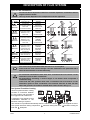
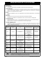
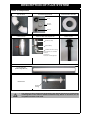
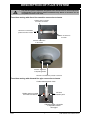
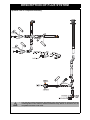
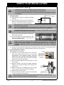
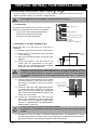
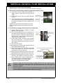
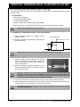
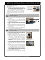
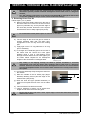
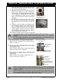
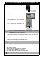
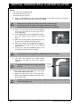
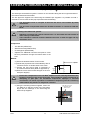
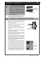
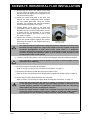
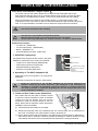
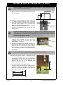
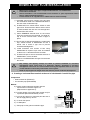
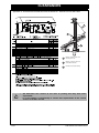
Flue Installation Manual
To Suit:
Rinnai Aspiration (Australia)
Rinnai Arriva (New Zealand)
RHFE-750ETR
Flame Fire Heater
Installation shall be in accordance with:
• Manufacturer’s Installation Instructions
• Current AS/NZS3000, AS/NZS3500 & AS5601
• Local Regulations and Municipal Building Codes
Installation, service and removal by an Authorised Person only.
Proudly a member of the A.G.A.
All our gas products are
A.G.A. certified
Distributed and serviced in Australia under a Quality
System certified as complying with ISO 9001 by
SAI Global
TABLE OF CONTENTS
IMPORTANT INFORMATION.................................................................................................. 3
DESCRIPTION OF FLUE SYSTEM......................................................................................... 4
Types of Flue Installations ............................................................................................................ 4
Flue System Transition Casting.................................................................................................... 4
Components ................................................................................................................................. 5
Photos of Components ................................................................................................................. 6
Transition casting with direct flue transition connection to heater ................................................ 7
Transition casting with elbowed flue pipe connection to heater.................................................... 7
Exploded view of component assembly........................................................................................ 8
Use of Silicone Grease ................................................................................................................. 9
Configuration Limitations .............................................................................................................. 9
DIRECT FLUE INSTALLATION ............................................................................................ 10
Getting started ............................................................................................................................ 10
Shortening Direct Flue Kit ........................................................................................................... 10
Extending Direct Flue Kit ............................................................................................................ 11
Access to flue connection at the Heater ..................................................................................... 12
Connecting and securing metal flue spigot from heater to flue .................................................. 12
VERTICAL ON WALL FLUE INSTALLATION...................................................................... 14
Components ............................................................................................................................... 14
Assembly of ‘On Wall’ Adaptation Kit ......................................................................................... 14
Access to flue connection at the heater ...................................................................................... 15
Connecting and securing metal flue spigot from heater to flue .................................................. 15
Connecting air supply elbow & final flue connection .................................................................. 15
VERTICAL THROUGH WALL FLUE INSTALLATION ......................................................... 16
Components ............................................................................................................................... 16
Installation of 'Horizontal section' of through wall flue ................................................................ 16
Shortening Direct Flue kit ........................................................................................................... 17
Extending Direct Flue Kit ............................................................................................................ 18
Creating a Horizontal Flue Terminal for a through the wall vertical flue system ......................... 20
Components ............................................................................................................................... 20
Method........................................................................................................................................ 21
SIDEWAYS HORIZONTAL FLUE INSTALLATION.............................................................. 22
Components ............................................................................................................................... 22
Method........................................................................................................................................ 22
DOWN & OUT FLUE INSTALLATION .................................................................................. 25
ASPKIT03 Components ............................................................................................................. 25
Assembly of "On Wall" Adaptation Kit ........................................................................................ 25
‘Down and Out’ heater recess dimensions ................................................................................. 25
Creating a horizontal flue terminal at the end of a horizontal Co-axial flue pipe ........................ 27
Access to the flue connection at the heater ................................................................................ 27
Connecting and securing metal flue spigot from heater to flue .................................................. 27
Connecting air supply elbow and final flue connection ............................................................... 27
CONNECTING THE CONDENSATE DRAIN HOSE ............................................................. 29
Condensate Kit ........................................................................................................................... 29
Connection of condensate hose to condensate trap .................................................................. 29
CLEARANCES ...................................................................................................................... 30
CONTACT INFORMATION ................................................................................................... 32
Rinnai
ii
RHFE-750ETR Flue Installation Manual
IMPORTANT INFORMATION
The Rinnai Aspiration (RHFE-750ETR) Co-axial flue system is certified as a component of the
Aspiration Flame Fire Heater. Only an Authorised person must install, service and remove the heater
and flue system.
The heater and the flue system shall be installed in accordance with:
• The requirements of AS 5601 'Gas Installations'
• Manufacturers installation instructions
• Local and Municipal building codes
• Any other relevant Statutory Regulation.
The Rinnai Aspiration Flame Fire Heater must be installed with the flue components designated in this
manual. Other components, whether manufactured by Rinnai or otherwise, are not compatible and
must not be used.
This manual must be read in accordance with the Aspiration Power Flued Flame Fire Heater
Operation/Installation manual supplied with the heater.
Rinnai appliance warranty conditions will be voided if non Rinnai flue components are fitted.
2. AVAILABLE CONFIGURATIONS
Rinnai
3
RHFE-750ETR Flue Installation Manual
DESCRIPTION OF FLUE SYSTEM
Types of Flue Installations
IMPORTANT
Options
I
Direct
II
A
Vertical
Extension
II
B
Vertical
Extension
III
A
Vertical
Extension
III
B
Vertical
Extension
IV
Sideways
Extension
V
Down & Out
Extension
Consult the Rinnai Aspiration Flame Fire Customer Operation / Installation manual
supplied with the heater.
Use only Rinnai Aspiration flue components with this appliance.
Components
Order Codes
‘Direct Flue’ Kit
ASPDFK
‘On Wall’ Kit
Co-axial Pipe 900mm*
Roof Cowl
Universal Wall Plate
ASPKIT03
ESPIPE900
ESROOFCOWL
ESPLATE
‘On Wall’ Kit
Co-axial Pipe 900mm*
Bends (2 x 45°)
Roof Cowl
ASPKIT03
ESPIPE900
ESBEND
ESROOFCOWL
‘Direct Flue’ Kit
Co-axial Pipe 900mm*
Bends (2 x 45°)
Condensate Trap
Roof Cowl
ASPDFK
ESPIPE900
ESBEND
ESCONDK
ESROOFCOWL
‘Direct Flue’ Kit
Co-axial Pipe 900mm*
Bends (2 x 45°)
Condensate Trap
Wall Terminal Kit
ASPDFK
ESPIPE900
ESBEND
ESCONDK
ESWTKIT
‘On Wall’ Kit
Co-axial Pipe 900mm *
Wall Terminal Kit
ASPKIT03
ESPIPE900
ESWTKIT
‘On Wall’ Kit
Co-axial Pipe 900mm*
Bends (2 x 45°)
Wall Terminal Kit
ASPKIT03
ESPIPE900
ESBEND
ESWTKIT
I
II
III
IV
V
DO NOT
DO NOT
* Order number of lengths as required
DO NOT
IMPORTANT
Flue is NOT to be terminated under the floor or in a roof space.
‘Down and Out’ and vertical through roof flue installations are permitted ONLY
when the flue terminal is located externally.
For horizontal installations there must be a continuous fall of at least 2° to the
termination point to drain condensate.
All terminations exceeding a vertical height of 1.5 metres must incorporate a
condensate trap.
‘Down and Out’ flue systems must have a continuous fall of at least 2° to the
termination point to drain condensate. Flue terminal must be at least 300 mm
above the ground in accordance with AS 5601 Clause 5.13.6.2 & Fig. 5.3.
Flue System Transition Casting
The flue system transition casting
provides a connection between
the flue system and the heater’s
flue spigot and air intake hose.
A minimum 5 mm clearance from
combustible materials to the
transition casting is required.
Options
I
Option
III
Option
II
IV
2
4
Flue system transition casting components:
inlet and 3 Wall plate.
V
1
1
2
1
2
3
1
4
1
This clearance is provided automatically when the 'stand off' brackets
Rinnai
Option
1
2
4
4
4
that are supplied are used.
transition casting flue outlet,
4
2
2
transition casting air
Installation Manual
DESCRIPTION OF FLUE SYSTEM
Components
Flue Terminals
•
Two styles of flue terminal are available, a wall terminal and vertical terminal.
Condensate trap
•
A condensate trap is required for any vertical flue system to ensure condensate generated in this
section of flue during combustion is trapped and prevented from entering the combustion
chamber of the Aspiration flame fire heater.
Bends
•
Bends are available as a pair of 45° angle bends. If a 90° bend is required the 2 x 45° bends are
joined.
Wall Plate
• Wall plates seal and secure the flue system when terminated horizontally.
• Wall plates are available as an individual item and can also be used as a ceiling plate.
Co-axial Flue Pipe
• Installed length 960 mm long. “O” ring seal jointing method. Pipe can be cut to desired length.
• Stand off clips for mounting are supplied with Co-axial flue pipe lengths.
"On Wall" Adaptation Kit
• Components to allow the Co-axial flue to run vertically or horizontally along the face of the wall
within the decorative enclosure around the heater. Also used to run Co-axial flue down or
sideways along the face of the wall.
TABLE OF COMPONENTS
Part Number
Description
ASPDFK
Direct Flue Kit
Use
Components included in kit
All (ASPDFK) components
Transition casting & horizontal terminal
Metal internal wall plate
Direct through wall kit for walls up to
Plastic external wall plate and
400 mm thick
Mounting screws
Installation Instructions
Small tub of silicone 'O' ring grease
Cable tie
ASPKIT03
“On Wall” flue kit
Adaptation kit for running
Co-axial flue on the face of wall
ESPIPE900
Co-axial flue pipe,
installed 960 mm long
Obtain the desired flue length.
Create horizontal terminal.
Extend length of Direct Flue Kit
(ASPDFK)
ESPLATE
Universal cover plate
ESWTKIT
Wall terminal kit horizontal
ESBEND
Condensate trap
Vertical adaptation casting
2 x Mounting brackets
Installation Instructions
Small tub of silicone 'O' ring grease
Cable tie
Bends (2 x 45°)
Change Co-ax flue pipe direction
2 x 45° Co-axial Bends
ESCONDK
Condensate Trap
Required when using through wall
vertical flue.
Included as a component in the
vertical “On Wall” flue kit
Condensation trap
ESROOFCOWL
Roof Cowl or
Vertical terminal
Vertical Flue Terminal
Rinnai
Roof terminal
(ESROOFCOWL)
Co-axial flue pipe(s)
(ESPIPE900)
Plastic cover plate suitable as a wall
cover plate or a ceiling ring.
Plastic wall plate and mounting screws
Suits Energysaver & Aspiration.
Plastic external wall plate
Plastic spacer sleeve
Flue terminal grill - screws
IMPORTANT
Co-axial pipe(s) for wall
thicker than 400 mm.
(ESPIPE900)
960 mm Co-axial flue pipe
Stand off clip
Creates a horizontal wall terminal
with a Co-axial flue pipe
(ESPIPE900)
•
Addition to be
purchased depending
on job
Vertical flue terminal
Only the flue system components designated in this manual must be used.
Components not designated in this manual, whether manufactured by Rinnai or
otherwise, are not compatible and must not be used.
5
RHFE-750ETR Flue Installation Manual
DESCRIPTION OF FLUE SYSTEM
Photos of Components
Pair 45° Bends
Horizontal Wall Terminal Kit
Universal External Wall Plate
Spacer
Universal
Wall Plate
End Grill
Condensate Trap
Vertical “On Wall” Flue Adaptation Kit
Vertical Terminal
Condensate Trap
Stand Off Clip
“On Wall” transition casting
Not shown but also included:
- Cable tie
- Instructions
- Container of ‘O’ Ring Grease
Co-axial Flue Pipe
(installed length 960 mm)
Direct Flue Kit
transition
casting
•
IMPORTANT
Rinnai
Only the flue system components designated in this manual must be used. Components
not designated in this manual, whether manufactured by Rinnai or otherwise, are not
compatible and must not be used.
6
RHFE-750ETR Flue Installation Manual
DESCRIPTION OF FLUE SYSTEM
•
IMPORTANT
Only the flue system components designated in this manual must be used. Components
not designated in this manual, whether manufactured by Rinnai or otherwise, are not
compatible and must not be used.
Transition casting with direct flue transition connection to heater
Rubber seal on unused
air intake connection
Direction of combustion
product flow from heater
Direction of air flow to
to heater
Air hose connection
to the heater
Direction of air flow
to Aspiration Heater
Direction of combustion product to terminal
Transition casting with elbowed flue pipe connection to heater
Condensate trap drain hose
Air hose
connection point
Rubber seal on unused
air intake connection
Elbow flue pipe connection
to Aspiration heater
flue spigot
Rinnai
7
RHFE-750ETR Flue Installation Manual
DESCRIPTION OF FLUE SYSTEM
Exploded view of component assembly
25mm
15mm
•
IMPORTANT
Rinnai
Only the flue system components designated in this manual must be used. Components
not designated in this manual, whether manufactured by Rinnai or otherwise, are not
compatible and must not be used.
8
RHFE-750ETR Flue Installation Manual
DESCRIPTION OF FLUE SYSTEM
Use of Silicone Grease
•
The inner flue pipe joints are sealed with an 'O' ring seal.
•
To ease assembly, lubricate the 'O' ring on the inner pipes prior to assembly
of components using the silicone based 'O' ring grease from the plastic jar
included with the direct flue kit or the 'On Wall' transition kit.
Configuration Limitations
Flue system length is limited to 6.5 metres and up to 2 x 90 degree bends can be used.
• The “On Wall” flue adaptation kit already contains one 90 degree bend. If this
kit is used only one additional 90 Co-axial bend (ESBEND) can be used.
NOTE
Rinnai
9
RHFE-750ETR Flue Installation Manual
DIRECT FLUE INSTALLATION
‘Direct Flue’ Installation (Page 4 - Option
I
)
• Standard "Direct Flue kit" is suitable for walls up to 400 mm thick.
• Flue can be cut to length if the wall thickness is less than 400 mm.
• Flue can be extended if wall thickness is greater than 400 mm using additional lengths of
NOTE
Co-axial pipe.
1. Getting started
Centre line of
appliance
a.) Select desired location for installing Aspiration
flame fire.
b.) The flue requires a hole of 100 mm diameter.
Mark the proposed penetration point through
the wall - in accordance with the diagram.
•
IMPORTANT
•
•
567mm
+/25mm
378m
Floor level
Ensure there are no wall studs, wiring or other obstruction within the wall cavity where the
flue is proposed to penetrate.
Ensure the proposed location of the flue terminal can comply with the requirements of AS
5601. Fig. 5.3 from AS 5601-2004 and additional information shown in Appendix A.
For weatherboard walls, drill a centering hole through the weatherboard from the inside
and then cut a 100 mm hole from the outside.
NOTE
c.) Drill the 100 mm flue penetration hole through
both sides of the wall.
d.) Ensure the fastening screws between the flue
pipe and transition casting on the direct flue
kit are secured as shown.
2 x Fastening Screws (second
screw on opposite side)
)
•
IMPORTANT
Ensure all connections to the transition casting on the direct flue kit are secured by the
relevant screws. Test soundness of the connections by attempting to 'pull apart' the
assembled components. Improper or unsound connections can result in products of
combustion dispersing into the room being heated which may lead to a dangerous
condition.
e.) Check the wall thickness to determine if the Direct Flue Kit needs to be shortened (wall is
less than 400 mm thick) or extended (wall is more than 400 mm thick).
2. Shortening Direct Flue Kit
wall plate
Follow Steps a.) to m.) below:
a.) Slide the round metal wall plate over the end of the
direct flue terminal all the way up to the 'stops'
incorporated in the transition casting. From the
inside of the room, push the direct flue kit through
the wall until the round metal cover plate rests firmly
against the inner wall (see photo).
NOTE: Flat section of
transition casting to
face toward the LHS of
heater so large air intake
connection is on the
bottom
Air intake connection
b.) Pull flue terminal assembly firmly through the wall
from outside.
c.) Mark the outside of the flue pipe (larger diameter)
allowing 15 mm past the edge of the external wall.
(See photo).
d.) Mark inner flue pipe an additional 25 mm in length
from the mark on the outer tube (see diagram).
15mm
e.) Remove direct flue from wall.
f.) Using a hacksaw or similar, cut off excess flue length
on both outer and inner flue pipes.
IMPORTANT
Rinnai
25mm
25 mm between end of alloy
inner and outer tubes to ensure
products of combustion are not
drawn back into air intake.
Measure 15 mm between edge
of external wall and edge of
alloy tube. (Not to edge of plastic
spacer)
Ensure that pipe cuts leave a clean, square edge and that the inner (smaller) flue pipe
protrudes 25 mm further than the larger (outer) pipe.
10
RHFE-750ETR Flue Installation Manual
DIRECT FLUE INSTALLATION
g.) Fit black plastic flue spacer to shortened flue outlet.
h.) Fit small black plastic flue outlet grill to the newly cut
inner flue pipe with the bars in a horizontal direction.
i.)
Slide newly cut shortened flue pipe through wall.
j.) Slide the plastic external wall cover plate over the
flue pipes on the outside of the wall, ensuring the
‘TOP’ symbol and mounting screw holes are on the
top side of the flue. This will ensure a 2 degree fall
for condensation to run towards the terminal.
“TOP” symbol to be aligned to
the top of external wall plate to
ensure 2 degree fall for condensation
to run toward outlet of flue terminal.
Location of stainless steel locking screw
k.) Pull flue terminal firmly through wall to ensure inner
metal plate is hard against inside wall. Centre the
outer terminal within the hole through the wall (see
Fasten 3 holes to wall with
photo).
screws supplied.
l.) Drill pilot hole into the outer flue pipe through the hole
in the plastic cover plate. Secure plastic cover plate
to outer flue pipe with stainless steel self-tapping
screw supplied. Attach plastic wall plate to the outer
wall with the screws supplied through the three
countersunk moulded into the plastic wall plate.
m.) Make connections between flue system and heater
in accordance with steps 4, 5 and 6.
•
IMPORTANT
The plastic cover plate must be secured by the screws as shown to prevent possible
accidental dislodgement which could result in a dangerous situation. For additional
security it is recommended that the optional 'flue guard' is fitted over the flue terminal.
3. Extending Direct Flue Kit
Follow steps a.) to o.) below:
a.) Remove the black plastic spacer from end of direct
flue. Do not discard as this will be re-used.
b.) Cut end of inner flue so it protrudes only 12 mm past
the edge of the outer alloy air tube. (See photo).
12mm
c.) Ensure end is cut square and there are no sharp or
rough edges.
Do not discard the black plastic spacer. It will be re-used later.
NOTE
d.) File edge of inner flue pipe to create a smooth
bevelled edge that will allow easy engagement of
"O" ring seal of the mating part.
e.) Apply light coat of "O" ring lubricant to "O" ring prior
to assembly.
f.) Fit a length of Co-axial flue pipe to the cut end of the
Direct Flue Kit. Secure the outer pipes together
using a rivet or self tapping screw (12 mm length)
through the area where the two outer pipes join as
shown. Repeat for all subsequent lengths of Coaxial flue pipe fitted.
•
IMPORTANT
Rinnai
Pop rivet or 12 mm
self tapping screw
Pop rivet(s) or self tapping screw(s) are fitted to prevent accidental or erroneous
dislodgement of the outer flue pipe(s) after installation which could result in a dangerous
situation. Otherwise accidental or erroneous dislodgement could occur as a result of future
servicing the Rinnai Aspiration heater or as a result of other activities in the vicinity of the
heater or flue system.
11
RHFE-750ETR Flue Installation Manual
DIRECT FLUE INSTALLATION
g.) Cut the length of outer tube so it protrudes past
external wall by 15 mm (as shown).
h.) Cut inner flue pipe so it protrudes past the outer
tube by 25 mm (as shown).
25mm
25 mm between end of alloy
inner and outer tubes to ensure
products of combustion are not
drawn back into air intake.
i.) Refit previously removed inner black plastic flue
spacer.
15mm
j.) Fit wall plate to wall, using the screws provided
through the three countersunk holes molded in
plastic wall plate. Ensure the Co-axial flue pipe
is centered within the 100 mm hole and the
'TOP' symbol on plastic wall plate is facing
toward the top.
Measure 15 mm between edge
of external wall and edge of
alloy tube. (Not to edge of plastic
spacer)
“TOP” symbol to be aligned to
the top of external wall plate to
ensure 2 degree fall for condensation
to run toward outlet of flue terminal.
Location of stainless steel locking screw.
k.) Pull flue assembly through wall and drill pilot hole
through edge of plastic wall plate and into the
outer pipe of the Co-axial flue.
l.) Secure plastic wall plate to outer Co-axial flue by
use of stainless steel screw provided.
m.) Align flue grill so the bars are in a horizontal
format.
•
IMPORTANT
Fasten 3 holes to wall with
screws supplied.
The plastic cover plate must be secured by the screws as shown to prevent possible
accidental dislodgement which could result in a dangerous situation. For additional security
it is recommended that the optional 'flue guard' is fitted over the flue terminal.
n.) Gently tap in flue grill into small flue pipe.
o.) Make connections between flue system & heater in accordance with steps 4, 5 and 6.
4. Access to flue connection at the Heater
To gain access to flue connection location at the heater:
a.) Remove the front cover and burner glass cover
of the heater.
G
F
b.) Remove 2 x self tapping screws from the flue
access panel located in the top left hand corner
of the rear panel of the appliance enclosure.
E
c.) Slide cover plate to the right.
5. Connecting and securing metal flue spigot from
heater to flue
a.) Lift locking tab from slide tube assembly on
heater. Remove slide tube from flue pipe on
heater.
Lift locking tab
Slide Tube
Remove slide tube
Rinnai
12
RHFE-750ETR Flue Installation Manual
DIRECT FLUE INSTALLATION
Slide Tube
b.) Fit flue slide tube into the flue system transition
casting.
Locking
Clamp
Direct
Flue
Transition
Casting
c.) Secure flue slide tube to the transition casting by
use of the locking clamp which is supplied with
the heater (Australia) or flue (NZ). Tighten screw
to secure.
Slide Tube from heater
Locking Clamp
The photo to the right shows the final assembly of
slide tube and transition casting locked together by
locking clamp.
Transition Casting
6. Connecting air supply elbow and final flue connection
•
Access for connections is gained by removal of flue access panel (step 4).
NOTE
a.) Position heater to allow connection of rubber
elbow and air supply tube.
b.) Connect rubber elbow from the air intake hose of
the heater onto the large hole on air inlet tube of
the flue transition. Secure with cable tie. Ensure
blanking cap is fitted to the unused socket on
transition casting. (see photo).
c.) Locate heater at the opening of the enclosure
and connect gas pipe. In accordance with the
instructions supplied with the heater. Check for
gas escapes.
Make sure rubber blanking
cap is in place
Ensure flue locking
clamp fastened
to secure flue
connection.
Cable tie fitted and
tightened to secure
rubber elbow to spigot.
d.) Re-fit side cover panel.
e.) Re-fit side access panel four retaining screws
then push the front edge of the panel close.
C
f.) Slide heater into enclosure. Be careful not to kink
the braided flexible gas hose.
g.) Reach through open rear slide panel, to slide flue
outlet from heater into the flue slide tube
protruding from the flue transition casting.
h.) Ensure the two stainless steel flue sections are
pushed together & engage with the locking clip.
i.) Slide flue access panel on top LHS of heater to
the left to close. Replace 2 x screws to secure.
j.) Secure heater via 2 x screws on the left and right
hand sides. (2 screws per side) in accordance
with Operation/Installation instructions supplied
with the heater.
•
IMPORTANT
•
Rinnai
Flue Transition
casting side
Clamp secured by
screw supplied
Check that the clip ‘locks’
to prevent accidental
dislodgement of flue pipe.
Heater side
Ensure the flue outlet from the heater is properly secured to the flue connection on the
transition casting using the clip and clamp provided. If this joint is not secured properly
products of combustion could disperse into the room being heated which may result in a
dangerous condition.
Ensure the elbow of the air intake hose is properly secured to the air intake connection on
the flue system transition piece using a cable tie and that the rubber blanking cap is placed
over the unused air intake connection of the transition casting.
13
RHFE-750ETR Flue Installation Manual
VERTICAL ON WALL FLUE INSTALLATION
‘Vertical On Wall’ Flue Installation - (Page 4 - Options
II
a. and
II
b.)
This flue system is used when the flue is to be run vertically up the face of the rear wall of the
heater enclosure to either a horizontal or vertical terminal.
•
The 'On Wall' flue kit is not suitable for installation inside a wall cavity.
NOTE
1. Components
Condensate Trap
The (ASPKIT03) components are shown in the photo.
Additional components which need to be obtained:
•
Lengths of Co-axial flue pipe (ESPIPE900)
•
Flue terminal (Vertical or Horizontal)
•
Universal cover plate (ESPLATE)
Stand Off Clip
“On Wall” transition casting
Not shown but also included:
- Cable tie
- Instructions
- Container of ‘O’ Ring Grease
2. Assembly of ‘On Wall’ Adaptation Kit
(Apply light coat of "O" ring seal to "O" rings prior to
assembly).
a.) Assemble components as shown in photo above.
b.) Ensure arrown on condensate trap is facing the
correct way (up).
Centre line of
appliance
c.) Mark centre of heater flue pipe on rear wall. (See
diagram).
d.) Ensure the location of the flue terminal can
comply with the requirements of AS 5601.
Figure 5.3 from AS 5601-2004 and additional
information are shown at Appendix A.
•
IMPORTANT
567mm
+/25mm
378m
Floor level
Ensure the components of the ‘On Wall’ adaptation kit are securely fastened to the transition
casting by the screws and rivets. Test soundness of the connections by attempting to ‘pull
apart’ the assembled components. Improper or unsound connections can result in products
of combustion dispersing into the room being heated which may result in a dangerous
condition.
e.) Using mounting bracket supplied, mount vertical
"On Wall" transition so the centre flue mark on
wall aligns to the centre of the flue connection
(see photo).
f.) Continue to build flue using appropriate lengths
of Co-axial flue pipes. Sockets of Co-axial flue
pipe to be at the flue terminal end. Fit stand off
clips supplied with ESPIPE900 to support the
weight of the flue system.
Centre flue connection
to align with centre
mark on wall
g.) Connect the condensate drain hose from the
outlet of the condensate trap to the evaporation
tray located inside the Aspiration heater. Refer
to section “CONNECTING THE CONDENSATE
DRAIN HOSE” on page 29.
NOTE
•
A small amount of 'O' ring lubricant will assist assembly.
•
Use PVC glue or similar between vertical joints of plastic (PVC) outer pipe to prevent ingress
of water.
h.) Terminate flue using a vertical roof terminal (ESROOFCOWL). Flue termination to comply
with the requirements of AS 5601 section 5 (See Appendix A). Flash the roof penetration by
appropriate methods. Roof flashing materials not included in flue kit.
Rinnai
14
RHFE-750ETR Flue Installation Manual
VERTICAL ON WALL FLUE INSTALLATION
3. Access to flue connection at the heater
Refer to section “Access to flue connection at the Heater” on page 12.
4. Connecting and securing metal flue spigot from heater to flue
a.) Lift locking tab from slide tube assembly on
heater. Remove slide tube from flue pipe on
heater.
b.) Fit flue slide tube into the flue system transition
casting.
c.) Secure flue slide tube to the transition casting by
use of the locking clamp which is supplied with
the heater (Australia) or flue (NZ). Tighten screw
to secure.
Ensure locking
clamp is in place
Tighten bolt
to lock clamp
into position
Photo to the right shows the final assembly of slide
tube & transition casting locked together by locking
clamp.
5. Connecting air supply elbow & final flue connection
a.) Position heater to allow connection of rubber
elbow and air supply tube.
b.) Connect rubber elbow from the air intake hose of
the heater onto the large hole on air inlet tube of
the flue transition. Secure with cable tie. Ensure
blanking cap is fitted to the unused socket on
transition casting. (see photo).
c.) Locate heater at the opening of the enclosure
and connect gas pipe. In accordance with the
instructions supplied with the heater. Check for
gas escapes.
Cable tie fitted and
tightened to secure
rubber elbow to spigot
To flue terminal
Rubber
blanking cap
in place
Air inlet
hose
Flue locking clamp fastened
to secure flue connection
d.) Re-fit side cover panel.
e.) Slide heater into enclosure. Be careful not to kink
the braided flexible gas hose.
f.) Reach through open rear slide panel, to slide flue
outlet from heater into the flue slide tube
protruding from the flue transition.
g.) Ensure the two stainless steel flue sections are
pushed together & engage with the locking clip.
h.) Slide flue access panel on top LHS of heater to
the left to close. Replace 2 x screws to secure.
i.) Secure heater via 2 x screws through on the left
and right hand sides. (2 screws per side) in
accordance with the customer/installation
instructions supplied with the heater.
Clamp secured by
bolt supplied
Locking clamp to
secure short stainless
flue pipe to flue
transition connection
•
Ensure the metal flue outlet from the heater is properly secured to the flue connection on the
transition casting using the clip and clamp provided. If this joint is not secured properly
products of combustion could disperse into the room being heated which may result in a
dangerous condition.
•
Ensure the elbow of the air intake hose is properly secured to the air intake connection on
the flue system transition piece using a cable tie and that the rubber blanking cap is placed
over the unused air intake connection of the transition casting.
IMPORTANT
Rinnai
Check that the clip ‘locks’ to prevent accidental
dislodgement of flue pipe
15
RHFE-750ETR Flue Installation Manual
VERTICAL THROUGH WALL FLUE INSTALLATION
‘Vertical through the Wall’ Flue Installation (Page 4 - Option
III
)
This system is suitable for appliances installed against solid brick walls, or where a direct flue terminal
cannot be used.
1. Components
•
Direct flue kit (ASPDFK)
•
Condensate trap (ESCONDK)
•
2 x 45° Bends (ESBEND)
•
Suitable number of Co-axial flue pipes (ESPIPE900)
•
Vertical terminal if required (ESROOFCOWL) Horizontal termination is also possible.
•
Maximum flue length not to exceed 6.5 metres.
NOTE
2. Installation of 'Horizontal section' of through wall flue
a.) Select desired location for installing Rinnai
Aspiration heater.
Flue penetration
b.) Mark the proposed flue penetration point through
the wall as shown.
Centre of
appliance
580mm
+/- 25mm
378mm
Base of enclosure
•
Ensure there are no studs / wiring or other obstructions within the wall cavity.
IMPORTANT
c.) Ensure location of the flue terminal can comply
with the requirements of AS 5601. Figure 5.3
from AS 5601-2004 & additional information are
shown at Appendix A.
d.) Ensure the fastening screws between the flue
pipe and transition casting of the Direct Flue Kit
are secured as shown.
•
IMPORTANT
2 x Fastening Screws (second
screw on opposite side)
Ensure all connections to the transition casting are secured by the relevant screws. Test
soundness of the connections by attempting to 'pull apart' the assembled components.
Improper or unsound connections can result in products of combustion dispersing into the
room being heated which may lead to a dangerous condition.
e.) Cut 100 mm diameter hole though wall to centre on pre location marked in step b).
f.) Check wall thickness to determine if Direct Flue Kit needs to be shortened (wall is less than
400 mm thick) or extended (wall is more than 400 mm thick).
•
The length of the direct flue kit pipes when used for a vertical through the wall installation
must be at least 300 mm.
IMPORTANT
Rinnai
16
RHFE-750ETR Flue Installation Manual
VERTICAL THROUGH WALL FLUE INSTALLATION
3. Shortening Direct Flue kit
follow steps a.) to j.)
a.) Slide the round metal wall plate over the end of
the Direct Flue Kit and push all the way up until
the round metal wall plate rests against the cast
stops incorporated in the transition casting.
Note: Flat section of
flue to face toward to
LHS of heater so large
air intake connection is
on the bottom
From inside the room, push the flue terminal
assembly through the wall until the round metal
wall plate rests firmly against the inner wall. (See
photo).
•
The length of the direct flue kit pipes when used for a vertical through the wall installation
must be at least 300 mm.
IMPORTANT
b.) Pull the flue assembly firmly through the wall from
the outside.
c.) Mark the outside of the air intake pipe (larger
diameter) allowing 50 mm past the edge of the
external wall. (See photo).
50 mm
12 mm
d.) Mark the inner flue pipe (smaller diameter) to
extend 12 mm past the end of the cut air intake
pipe.
e.) Remove Direct Flue Kit from the wall and remove
black plastic spacer. (Do not discard spacer it will
be used later).
f.) Using a hacksaw or similar, cut off excess flue
length on both outer and inner flue pipes.
•
IMPORTANT
Ensure that the pipe cuts leave a clean, square edge on both cuts and that the protrusion
distances are correct.
g.) Slide the newly cut flue pipes through the wall,
and centre the positioning of the outer flue pipe
within the hole through the wall.
h.) Slide plastic external wall cover plate over the flue
pipes on the outside of the wall, ensuring the
'TOP' symbol is at the BOTTOM side of the flue.
This will ensure a 2 degree fall for condensation
to run TOWARDS the heater which is required
ONLY for the through wall Vertical Co-axial flue
installation.
“TOP” marking on
BOTTOM of plastic spacer
(through wall vertical co-axial
installation only).
i.) Pull flue terminal firmly through the wall to ensure
the round inner metal wall plate is hard against
the internal wall. Centre flue within the 100 mm
hole.
j.) Drill pilot hole in the plastic cover plate and into
the air intake pipe. Secure the components with
the self tapping stainless steel screw supplied.
Attach the plastic wall plate to the wall using the
screws supplied through the three countersunk
holes moulded into the plastic wall plate. Ensure
flue is centered within in the hole.
The installation should now look like photo on the right.
Rinnai
17
RHFE-750ETR Flue Installation Manual
VERTICAL THROUGH WALL FLUE INSTALLATION
•
IMPORTANT
•
The horizontal section of the flue system must be secured by the screws or rivets as
described to prevent possible accidental dislodgement which could result in a dangerous
situation.
The ‘TOP’ marking on the pastic cover must be at the BOTTOM for through the wall vertical
co-axial flue installations only to ensure correct condensate drainage.
4. Extending Direct Flue Kit
Follow steps a.) to m.) below
a.) Remove the black plastic spacer from the end of
the Direct Flue Kit. Cut the end of the inner flue
pipe so it protrudes only 12 mm past the edge of
the outer alloy air tube. Ensure the cut is square
and that there are no sharp edges (See photo).
•
12mm
Do not discard the black plastic spacer as it will be re-used later.
NOTE
b.) File the edge of the inner flue pipe to create a
smooth bevelled edge that will allow easy
engagement of the 'O' ring seal of the mating
part.
c.) Apply light coat of "O" ring lubricant to "O" ring
prior to assembly.
d.) Fit a length of Co-axial flue pipe to the cut end of
the Direct Flue Kit. Secure the outer pipes
together using a rivet or self tapping screw
through the area where the two outer pipes join
as shown below. Repeat for all subsequent
lengths of the horizontal Co-axial pipe fitted.
•
IMPORTANT
Pop rivet or 12 mm
self tapping screw
Pop rivet(s) or self tapping screw(s) are fitted to prevent accidental or erroneous
dislodgement of the outer flue pipe(s) after installation which could result in a dangerous
situation. Otherwise accidental or erroneous dislodgement could occur as a result of future
servicing the Aspiration heater or as a result of other activities in the vicinity of the heater or
flue system.
e.) Pull the flue assembly firmly through the wall from
the outside.
f.)
Mark the outside of the air intake pipe (larger
diameter) allowing 50 mm past the edge of the
external wall. (See photo).
50 mm
12 mm
g.) Mark the inner flue pipe (smaller diameter) to
extend 12 mm past the end of the cut air intake
pipe.
h.) Remove Direct Flue Kit from the wall.
i.) Using a hacksaw or similar, cut off excess flue
length on both outer and inner flue pipes.
•
IMPORTANT
Rinnai
Ensure that the pipe cuts leave a clean, square edge on both cuts and that the protrusion
distances are correct.
18
RHFE-750ETR Flue Installation Manual
VERTICAL THROUGH WALL FLUE INSTALLATION
j.) Slide the newly cut flue pipes through the wall,
and centre the positioning of the outer flue pipe
within the hole through the wall.
k.) Slide plastic external wall cover plate over the flue
pipes on the outside of the wall, ensuring the
'TOP' symbol is at the BOTTOM side of the flue.
This will ensure a 2 degree fall for condensation
to run TOWARDS the heater which is required
ONLY for the through wall Vertical Co-axial flue
installation.
l.) Pull flue terminal firmly through the wall to ensure
the round inner metal wall plate is hard against
the internal wall. Centre flue within the 100 mm
hole.
“TOP” marking on
BOTTOM of plastic spacer
(through wall vertical co-axial
installation only).
m.) Drill pilot hole in the plastic cover plate and into
the air intake pipe. Secure the components with
the self tapping stainless steel screw supplied.
Attach the plastic wall plate to the wall using the
screws supplied through the three countersunk
holes moulded into the plastic wall plate. Ensure
flue is centered within in the hole.
The installation should now look like photo on the right.
•
IMPORTANT
•
The horizontal section of the flue system must be secured by the screws or rivets as
described to prevent possible accidental dislodgement which could result in a dangerous
situation.
The ‘TOP’ marking on the pastic cover must be at the BOTTOM for through the wall vertical
co-axial flue installations only to ensure correct condensate drainage.
5. Access to the flue connection at the heater
Refer to section “Access to flue connection at the
Heater” on page 12.
6. Connecting and securing metal flue spigot
from heater to flue
Refer to section “Connecting and securing metal flue
spigot from heater to flue” on page 12.
7. Connecting air supply elbow and final flue
connection
Refer to section “Connecting air supply elbow and
final flue connection” on page 13.
Make sure rubber blanking
cap is in place
Ensure flue locking
clamp fastened
to secure flue
connection.
Cable tie fitted and
tightened to secure
rubber elbow to spigot.
Flue Transition
casting side
Clamp secured by
screw supplied
Check that the clip ‘locks’
to prevent accidental
dislodgement of flue pipe
Heater side
•
IMPORTANT
•
Rinnai
Ensure the flue outlet from the heater is properly secured to the flue connection on the
transition casting using the clip and clamp provided. If this joint is not secured properly
products of combustion could disperse into the room being heated which may result in a
dangerous condition.
Ensure the elbow of the air intake hose is properly secured to the air intake connection on
the flue system transition piece using a cable tie and that the rubber blanking cap is placed
over the unused air intake connection of the transition casting.
19
RHFE-750ETR Flue Installation Manual
VERTICAL THROUGH WALL FLUE INSTALLATION
8. Installing vertical section of ‘Through Wall’
Flue
a.) Cut the black plastic spacer and fit into the ends
of the horizontal flue pipe protruding through the
outside wall.
Cut off raised section
and discard. Refit
remaining spacer into
end of flue pipe.
b.) Fit the 2 x 45° bends as shown to the end of the
flue protruding through the wall.
c.) Fit condensate trap to 45° bend as shown with the
'UP' marking facing that way.
d.) Run a condensate drain pipe from the red drain
connection on the condensate trap in accordance
with AS 3500 ‘National Plumbing and Drainage’.
“TOP” marking on bottom
of plastic spacer to
ensure 2° fall of direct
flue back toward heater
•
IMPORTANT
Because the condensate is mildly acidic, Rinnai recommend Clipsal 16 mm rigid Grey
UPVC or equivalent conduit and associated fittings: Grey UPVC Pipe (Catalogue # 9016MD),
90° elbow (Catalogue # 261/16).
Copper tube must not be used as it may corrode.
e.) The remaining Co-axial flue pipes can now be run vertically up the face of the external wall.
Clip the Co-axial flue pipes to the wall using the clips provided (One clip per length of Coaxial pipe). Flue can terminate vertically or horizontally in compliance with AS 5601 (See
Appendix A).
If the vertical roof terminal is used, ensure compliance with AS 5601 Section 5 (See Appendix
A). Flash the roof penetration by appropriate methods. Roof flashing materials not included in
flue kit. If a horizontal terminal is required, refer to Step 9 below.
•
A small amount of ‘O’ ring lubricant will assist assembly.
•
Use PVC glue or similar between vertical joints of plastic (PVC) outer flue pipe to prevent
ingress of water.
NOTE
9. Creating a Horizontal Flue Terminal for a through the wall vertical flue system
Components
•
Pair 45° Bends (ESBEND).
•
Horizontal wall terminal Kit (ESWKIT) wall plate not used.
•
Co-axial flue pipe for vertical flue length (ESPIPE900).
•
Co-axial flue pipe to create horizontal flue terminal (ESPIPE900).
•
A ‘cut off’ section of pipe left over can be used for this purpose.
NOTE
Rinnai
20
RHFE-750ETR Flue Installation Manual
VERTICAL THROUGH WALL FLUE INSTALLATION
Method
•
Use off-cut of Co-axial flue pipe.
•
Cut inner flue 170 mm long.
•
Cut outer flue 100 mm long.
a.) Using an ESPIPE900, (or off-cut from ESPIPE900) cut the alloy inner pipe to 170mm in
length and the outer plastic pipe to 100 mm in length.
NOTE
•
Ensure flue is cut at the 'non socket' or free end of Co-axial flue pipe.
•
Flue off-cuts must be cut square and left with a smooth beveled edge.
•
A small amount of 'O' ring lubricant on rubber seals will assist assembly.
b.) Fit the 170 mm inner flue pipe to inner ESBEND
and secure with either a 12 mm long screw or
rivet. (See photo).
c.) Fit the additional inner alloy ESBEND to create a
90° bend. Secure with a screw or rivet. (See
photo).
Pipe attached
with screw
or rivet
d.) Slide 100 mm long plastic outer plastic flue over
the end of the 170 mm long inner alloy flue.
e.) Slide pair of plastic outer ESBEND components
over the end of the pair of alloy inner ESBEND
components.
f.)
Fit the inner and outer ESBEND pipes to the
socket of the vertical Co-axial flue pipe.
•
A small amount of ‘O’ ring lubricant on rubber seals will assist assembly.
NOTE
g.) Use PVC glue between the mating plastic
components (sockets) to ensure flue system
security.
•
NOTE
Ensure flue terminal is facing directly away from
the wall.
Stand-off clip
to secure
vertical pipe
to wall
Plastic fittings glued
with PVC glue to
ensure flue outlet
faces away from the wall
h.) Slide spacer into the end of the of the outer plastic
flue terminal pipe. (See photo).
i.) Gently tap end grill into end of inner alloy pipe.
Bars to be installed horizontally across the end of
the inner flue pipe.
•
NOTE
Rinnai
Use PVC glue between the mating plastic components (sockets) to ensure flue system is
secure and weather proof.
21
RHFE-750ETR Flue Installation Manual
SIDEWAYS HORIZONTAL FLUE INSTALLATION
‘Sideways Horizontal’ Flue Installation - (Page 4 - Option
IV
)
The sideways horizontal flue system is used to run Co-axial flue along the left or right hand side of
the internal wall behind the heater.
The flue pipes are clipped to the wall using the standoff clips supplied. It is possible to build a
decorative cover around the flue pipe exposed inside the building.
NOTE
•
The decorative cover is not part of this flue kit and is not covered by these
instructions.
•
The 90° bend incorporated within the 'On Wall' transition is counted as ONE 90°
Bend.
Creating a fall within flue system:
•
Sideways horizontal flue systems should have a 2° fall toward the flue terminal to
drain out any condensation.
•
There should be a 25 mm clearance between the outer co-axial flue pipe and any
decorative cover.
IMPORTANT
Components
•
'On Wall' Kit (ASPKIT03)
•
Wall Terminal Kit (ESWTKIT03)
•
Co-axial pipes (ESPIPE900)
•
Optional: An additional universal cover plate to cover
the flue penetration through the internal side of the
wall.
Method
a.) Select the desired location for the heater.
Centre line of
appliance
b.) Decide the proposed route of the sideways flue &
confirm there are no obstructions to this route.
c.) Ensure the flue will be able to terminate in
accordance with AS 5601 (Refer to Appendix A).
d.) Mark the centre of the heater flue pipe on the rear
wall (see diagram).
•
IMPORTANT
378m
Floor level
Ensure the components of the ‘On Wall’ adaption kit are securely fastened to the
transition casting by the screws and rivets. Test soundness of the connections by
attempting to ‘pull apart’ the assembled components. Improper or unsound
connections can result in products of combustion dispersing into the room being
heated which may result in a dangerous condition.
e.) Using the mounting bracket supplied, mount the
‘On Wall’ kit so that the centre of the flue pipes
aligns with the markings on the wall using the
stand off clip supplied.
Rinnai
567mm
+/25mm
22
Centre flue connection
to align with centre
mark on wall
RHFE-750ETR Flue Installation Manual
SIDEWAYS HORIZONTAL FLUE INSTALLATION
•
NOTE
The ‘On Wall’ kit can run horizontally to the
‘left’ or to the ‘right’ at the rear of the heater
as shown in the photo above. In a sideways
horizontal flue system the positioning and
direction of the condensate trap do not
matter as no condensate will be collected
and drained. Condensate drainage is
ensured by the two degree ‘fall’ towards
the terminal. Condensate trap must still be
fitted as part of flue system. Straight end of
co-axial flue pipe fits into end of
condensate trap socket.
Direction of flue discharge
Straight end of
co-axial flue pipe
fitted into end of
condensate trap socket
Condensate trap
connection facing down
f.) Continue to fit additional lengths of Co-axial flue
pipe until the required flue length is obtained.
IMPORTANT
•
Socket end of the Co-axial flue pipe must face the flue termination.
•
A small amount of ‘O’ ring grease applied to the seals will aid assembly.
g.) Mark the last length of the outer flue pipe (larger
diameter) allowing 15 mm past the edge of the
external wall (see photo).
h.) Mark the last length of inner flue pipe an
additional 25 mm in length from the mark on the
outer air intake tube (see diagram).
i.) Remove the last length of Co-axial pipe flue
assembly from the rest of the assembled flue
system.
j.) Using a hacksaw or similar, cut off excess flue
length from both the outer and inner pipes of the
last length of Co-axial pipe.
25mm
25 mm between end of alloy
inner and outer tubes to ensure
products of combustion are not
drawn back into air intake.
15mm
Measure 15 mm between edge
of external wall and edge of
alloy tube. (Not to edge of plastic
spacer)
k.) Slide the plastic internal wall cover plate from the
wall terminal kit (ASPKIT03) over the last flue
pipe inside the building (if required).
l.) Pass the last flue pipe (now cut off) through the
wall and attach to the rest of the flue assembly.
Ensure wall plate location is in centre of hole
through wall. Fasten the internal wall plate to the
wall through the 3 pre-drilled holes in the cover
plate using suitable screws.
m.) Fit the black plastic spacer from the wall terminal
kit (ESWTKIT) between the inner and outer pipes
of the last length of Co-axial pipe (see photo).
n.) Fit small black plastic flue outlet grill from the wall
terminal kit (ESWTKIT) to the innter flue pipe
with the bars in a horizontal direction (see photo).
o.) Slide the plastic external wall cover plate over the
flue pipes on the outside of the wall, ensuring the
“TOP” symbol and mounting screw hole is on the
top side of the flue. (This will ensure a 2 degree
fall for condensation to run towards the outlet).
Rinnai
23
RHFE-750ETR Flue Installation Manual
SIDEWAYS HORIZONTAL FLUE INSTALLATION
p.) Drill through the hole in the plastic cover plate
and into metal air intake pipe. Secure with the
stainless steel self-tapping screw supplied to lock
the flue terminal in place.
q.) Attach the plastic wall plate to the outer wall
through the three countersunk holes moulded
into the plastic wall plate using the screws
supplied. The finished flue terminal assembly
should look like the photo to the right.
“TOP” symbol to be aligned
to the top of external wall
plate to ensure 2° fall for
condensation to run toward
outlet of flue terminal
r.) Fasten plastic cover plate to the wall with
appropriate screws (3 holes).‘TOP’ symbol to be
aligned to the top of external wall plate to ensure
2 degree fall for condensation to run toward
outlet of flue terminal. Use fixing screw to lock
flue system in place.
s.) Fasten the remaining horizontal Co-axial flue
pipes now joined together against the internal
wall using the stand off clip supplied with each
Co-axial flue pipe.
•
IMPORTANT
Hole for fixing screw through
external wall cover plate
into air intake tube.
Fasten 3 holes to wall
with screws supplied.
It is important that the horizontal Co-axial flue pipes are fastened to the wall using
the stand off clips supplied to support the weight of the flue system and prevent
accidental dislodgement of pipe joints which could result in a dangerous
situation. Otherwise accidental or erroneous dislodgement could occur as a result
of future servicing the Aspiration heater or as a result of other activities in the
vicinity of the heater or flue system.
t.) Construct and fit a decorative cover over the horizontal pipe inside the building if required.
•
There should be a 25 mm clearance between the outer Co-axial flue pipe and any
decorative cover materials.
IMPORTANT
u.) Access to the flue connection at the heater
Refer to section “Access to flue connection at the Heater” on page 12.
v.) Connecting and securing metal flue spigot from heater to flue
Refer to section “Connecting and securing metal flue spigot from heater to flue” on page 15.
w.) Connecting air supply elbow and final flue connection
Refer to section “Connecting air supply elbow and final flue connection” on page 15.
•
Ensure the flue outlet from the heater is properly secured to the flue connection
on the transition casting using the clip and clamp provided. If this joint is not
secured properly products of combustion could disperse into the room being
heated which may result in a dangerous condition.
•
Ensure the elbow of the air intake hose is properly secured to the air connection
on the flue system transition piece using a cable tie and that the rubber blanking
cap is placed over the unused air intake connection of the transition casting.
IMPORTANT
Rinnai
24
RHFE-750ETR Flue Installation Manual
DOWN & OUT FLUE INSTALLATION
‘Down & Out’ Flue Installation - (Page 4 - Option V )
The ‘Down and Out’ flue options allows the ‘On Wall’ kit and condensate trap to face
downwards and the flue pipe to be run vertically down through a hole in the floor and then
horizontally to a suitable location outside. Flue is not to terminate beneath the building.
Flue must terminate in accordance with AS 5601 Figure 5.3. Especially relevant is the
requirement to have a minimum of 300 mm clearance between the flue terminal and ground
level. It is not permissible to excavate a hole to obtain the required 300 mm clearance.
•
Flue must not terminate under a building.
•
•
•
Flue terminal is only available in the horizontal format.
Maximum total flue length not to exceed 6.5 metres and 2 x 90° bends.
The 90° bend incorporated within the 'On Wall' transition is counted as ONE 90° Bend).
IMPORTANT
NOTE
Components Required
•
‘On Wall’ Kit - (ASPKIT03)
•
Co-axial Flue Pipe(s) - (ESPIPE900)
•
Bends - (ESBEND x 2)
•
Universal Wall Cover Plate - (ESPLATE)
1. ASPKIT03 Components
Condensate Trap
The (ASPKIT03) components are shown in the photo.
Additional components which need to be obtained:
• Lengths of Co-axial flue pipe (ESPIPE900)
•
•
Stand Off Clip
Flue terminal (Vertical or Horizontal)
(ESROOFCOWL) & (ESWTKIT)
“On Wall” transition casting
Not shown but also included:
- Cable tie
- Instructions
- Container of ‘O’ Ring Grease
Universal cover plate (ESPLATE)
2. Assembly of "On Wall" Adaptation Kit
(Apply light coat of "O" ring seal to "O" rings prior to
assembly).
•
Assemble components as shown in photo above.
•
IMPORTANT
Ensure the components on the ‘On Wall’ adaptation kit are securely fastened to the
transition casting by the screws and rivets. Test soundness of the connections by
attempting to ‘pull apart’ the assembled components. Improper or unsound connections
can result in products of combustion dispersing into the room being heated which may
result in a dangerous condition.
3. ‘Down and Out’ heater recess dimensions
Transition
Casting
Flue Outlet
m
500 m
R
EN EAR
CL O
OS F
UR
E
E
R
SU
LO
NC
FE
TO
ON
a.) Select the desired location for the heater.
FR
If the ‘Down and Out’ flue option is used the recess
in which the Rinnai Aspiration heater is installed
needs to be 50 mm deeper than the normal
installation (500 mm deep instead of 450 mm
deep). Refer Rinnai Aspiration heater Operation/
Installation manual for details.
Transition
Casting
Air Inlet
b.) Decide the proposed route of the sideways flue and confirm there are no obstructions to
this route, for example, floor joists, bearers, stumps, ductwork etc.
c.) Ensure the flue will be able to terminate in accordance with AS 5601 (Refer to Appendix A).
Also ensure there is sufficient clearance beneath the building to obtain a minimum of 300
mm between the bottom of the horizontal flue terminal and the normal ground level.
Rinnai
25
RHFE-750ETR Flue Installation Manual
DOWN & OUT FLUE INSTALLATION
•
Ground excavation is not recommended to meet clearance or space requirements unless
there is sufficient drainage provision.
NOTE
d.) Mark the centre of the heater flue pipe on the rear
wall (see photo).
Centre line of
appliance
567mm
+/25mm
378m
Floor level
e.) Using the mounting brackets supplied, mount the
‘On Wall’ kit with so that the centre of the flue
pipes aligns with the markings on the wall using
the stand off clips supplied. The condensate trap
should be pointing towards the floor.
Mark centre of hole through floor directly beneath
centre of condensate trap. Cut 100 mm dia. hole
through floor.
•
NOTE
•
Centre flue connection
to align with centre
mark on wall
In ‘Down and Out’ applications only, the ‘up’ marking on the condensate trap will point
‘down’. This is normal. In a ‘Down and Out’ application, the positioning and direction of the
condensate trap do not matter as no condensate will be collected & drained. Condensate
drainage is ensured by the two degree ‘fall’ towards the terminal.
Condensate trap must still be fitted.
f.) Fit 2 x 45° bends (ESBEND) together and fit the
resulting bend assembly to the ‘free’ (non
socketed) end of a Co-axial flue pipe
(ESPIPE900) - see photo.
bend
assembly
free end
g.) Mount the ESPIPE900 and bends temporarily in
the horizontal plane beneath the floor, using the
stand off clip for correct spacing under bearers
etc. so that the free end of the bend assembly
faces vertically up towards the condensate trap
(see photo).
•
bend
assembly
A small amount of ‘O’ ring lubricant on rubber seals will assist assembly.
NOTE
h.) Measure the vertical distance ‘Y’ between the free
end of the ESBEND’s and the condensate trap.
This distance will be used to cut a Co-axial pipe
(ESPIPE900) to the correct length to join
between the free end of the ESBEND and
condensate trap - see photo.
i.) Cut an ESPIPE900 to length as follows:
Length of outer pipe is distance ‘Y’ plus 60 mm to
allow for connection penetration to mating part.
Ensure the inner pipe extends 12 mm past the
outer pipe - (‘Y’ plus 72).
‘Y’+ 60mm
‘Y’
12mm
‘Y’+ 72mm
Rinnai
26
RHFE-750ETR Flue Installation Manual
DOWN & OUT FLUE INSTALLATION
NOTE
•
•
•
•
Measure from socket end of pipe. Cut pipe and discard ‘free’ non socketed end.
Cut end to be left smooth.
Ground excavation is not recommended to meet clearance or space requirements unless
there is sufficient drainage provision.
A small amount of ‘O’ ring lubricant on rubber seals will assist assembly.
j.) Assemble vertical ‘Down’ section of the flue with
the STRAIGHT END of the ESPIPE900 fitted to
the end of the condensate trap.
k.) Fit ESPLATE over vertical 'Down' section to seal
gap in floor. Ensure that the 'Down' section of flue
is centered within the 100 mm hole through floor.
Screw ESPLATE to floor.
l.)
Attach ESBENDS beneath floor so the socket
ends face toward the flue terminal. Fit stand offclip to secure vertical 'Down' section of pipe in
place.
m.) Secure the socket joints between the condensate
trap, vertical section of ESPIPE900 and the 2
bends. Use a screw or pop rivet to prevent
accidental dislodgement.
n.) Install horizontal 'Out' section of flue using
ESPIPE900 as required. Pipe must be installed
so there is a 2° fall toward the flue terminal.
o.) Fit stand-off clips to secure horizontal sections of
ESPIPE900 in correct location.
Pop rivet or 12 mm
self tapping screw
p.) Continue until ESPIPE900 emerges from beneath
the house.
•
Pop rivet(s), self tapping screw(s) are fitted to prevent accidental or erroneous
dislodgement which could result in a dangerous situation. Accidental or erroneous
dislodgement could occur as a result of future servicing the Aspiration heater or as a result
of other activities in the vicinity of the heater or flue system.
•
Stand off clips support the weight of the flue and also prevent accidental dislodgement.
IMPORTANT
4. Creating a horizontal flue terminal at the end of a horizontal Co-axial flue pipe
Components
•
Wall Terminal Kit (ESWTKIT)
•
Co-axial flue pipe (ESPIPE900)
Method
a.) Ensure location selected complies with the
requirements of AS 5601 Figure 5.3
(Reproduced in Appendix A).
b.) Cut outer length of air supply tube (socket end) so
it protrudes past external wall by 15 mm.
c.) Cut inner flue pipe so it protrudes past the end of
the air supply tube by 25 mm.
d.) Fit inner flue spacer.
e.) Fit Wall plate.
15mm
f.) Gently tap in flue grill into small flue pipe.
Rinnai
25mm
25 mm between end of alloy
inner and outer tubes to ensure
products of combustion are not
drawn back into air intake.
Measure 15 mm between edge
of external wall and edge of
alloy tube. (Not to edge of plastic
spacer)
27
RHFE-750ETR Flue Installation Manual
DOWN & OUT FLUE INSTALLATION
g.) Centre plastic wall plate and fasten to wall with the
screws provided. 'TOP' symbol of wall plate
should be facing upwards to ensure a 2° fall
toward the flue terminal is maintained to allow
any condensation to drain away from the heater.
“TOP” symbol to be aligned
to the top of external wall
plate to ensure 2° fall for
condensation to run toward
outlet of flue terminal
h.) Drill hole through lip of wall plate through outer air
pipe and plastic spacer and secure with stainless
steel fixing screws provided.
Hole for fixing screw through
external wall cover plate
into air intake tube.
Fasten 3 holes to wall
with screws supplied.
•
IMPORTANT
The plastic cover plate must be secured by the screws as shown to prevent possible
accidental dislodgement which could result in a dangerous situation. For additional
security it is recommended that the optional ‘flue guard’ is fitted over the flue terminal.
\
5. Access to the flue connection at the heater
Refer to section “Access to flue connection at the Heater” on page 12.
6. Connecting and securing metal flue spigot from heater to flue
Refer to section “Connecting and securing metal flue spigot from heater to flue” on page 15.
5. Connecting air supply elbow and final flue connection
Refer to section “Connecting air supply elbow and final flue connection” on page 15.
Rinnai
28
RHFE-750ETR Flue Installation Manual
CONNECTING THE CONDENSATE DRAIN HOSE
1. Condensate Kit
The condensate tray will be supplied with the
‘Stand Off’ wall bracket and must be fitted as per
the supplied instructions in conjunction with every
condensate trap.
Condensate tray components:
• Condensate Tray
• Condensate Tube
• Condensate Hose
• Wire tie
2. Connection of condensate hose to condensate trap
The free end of the clear plastic condensate drain
hose located at the rear of the heater is required
to be fitted to the red rubber connection on the
condensate trap of the flue system.
Push end of clear plastic hose inside the red
rubber connection on the condensate trap.
Push fully in until clear plastic hose reaches the
end of the red rubber connection point.
With ‘On Wall’ vertical flue installations (Page 4 Option II ) condensate is discharged to the
condensate tray via the drain hose.
•
Ensure that there is no kink in the condensate hose and keep away from hot
surfaces.
IMPORTANT
•
IMPORTANT
Rinnai
Only the flue system components designated in this manual must be used.
Components not designated in this manual, whether manufactured by Rinnai or
otherwise, are not compatible and must not be used.
29
RHFE-750ETR Flue Installation Manual
CLEARANCES
Appendix 'A'- Horizontal and Vertical flue terminal clearances - Extracts from AS 5601:2004.
a
c
b
•
NOTE
Rinnai
a
Minimum clearance 500 mm to
nearest part of roof.
b
Minimum clearance 25mm to
combustible materials.
c
Decktite or lead collar flashing.
AS 5601-2004 was current at the time of printing but may have been
superseded.
It is the Installer's responsibility to ensure that requirements of the current
version of AS 5601 are met.
30
RHFE-750ETR Flue Installation Manual
NOTES
Rinnai
31
RHFE-750ETR Flue Installation Manual
CONTACT INFORMATION
Australia Pty. Ltd.
Head Office
ABN 74 005 138 769
Internet: www.rinnai.com.au E-mail: [email protected]
10-11 Walker Street,
Braeside, Victoria 3195
P.O. Box 460
Tel: (03) 9271 6625
Fax: (03) 9271 6622
National Help Lines
Spare Parts & Technical Info
Tel: 1300 555 545*
Fax: 1300 300 141*
Rinnai has a Service and Spare Parts network with personnel who are fully trained
and equipped to give the best service on your Rinnai appliance. If your appliance
requires service, please call our Hot Water Service Line. Rinnai recommends that
this appliance be serviced every 3 years.
*Cost of a local call Higher from mobile or public phones.
Internet: www .rinnai.co.nz E-mail: [email protected]
New Zealand Ltd.
Consumer Enquiries
Head Office
Tel: 0800 746624 (0800 Rinnai)
691 Mt. Albert Road,
Royal Oak, Auckland
P.O. Box 24-068
Tel: (09) 625 4285
Fax: (09) 624 3018
Installer Enquiries
Tel: 0800 86746624 (0800 TO RINNAI)
32
RA TSD - 04.080 RHFE-750ETR Flue Inst. Issue 4, 23/1/08