1
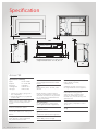
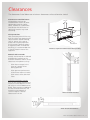
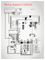
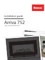
Installation guide
Arriva 752
Models: RHFE752ETRN/RHFE752ETRL
Important:
Appliance must be installed with a Rinnai approved flue
system.
This appliance shall be installed in accordance with:
-- Manufacturer’s installation instructions
-- AS/NZS 5601
-- Local regulations and municipal building codes
Installation, servicing and repair shall be carried out only by
authorised personnel.
Please retain this manual for future reference.
Warning
Improper installation, adjustment, alteration, service or
maintenance can cause property damage, personal injury
or loss of life.
For more information about buying, living and servicing
of Rinnai appliances call: 0800 RINNAI (0800 746 624)
Rinnai New Zealand Limited
105 Pavilion Drive, Mangere, Auckland
PO Box 53177, Auckland Airport, Auckland 2150
Phone:(09) 257 3800, Fax: (09) 257 3899
Email: [email protected], www.rinnai.co.nz
:
s
t
n
e
cont
Specification4
Clearances5
Location6
Gas connection7
Flueing options8
Flueing guidelines9
Arriva flue components10
Flue transition12
Installation13
Installing the burn media14
Commissioning15
Setting the air guide vane
15
Panel installation16
Flame pattern17
Installation checklist18
Wiring diagram19
Specification
710
1050
76
230
B
845
365
660
A
Double fronted fascia: A = 98, B = 20
Single fronted fascia: A = 90, B = 12
365
Arriva 752
Specification summary
Input
= 8-31.5 MJ/h
Output
= 1.8-7.0* kW
Efficiency
= 79-89%*
Heating area
= 70-95 m²**
Gas type
= NG or LPG
* Will vary according to gas type and
flue configuration.
** Will vary depending on geographical
location in NZ.
Inbuilt convector space heater with
forced convection and power flue
system.
Burners
Ember bed and flame burner.
Combustion system
Yellow flame and bunsen multi port
burner.
Data plate
Inside appliance, upper right hand
side, behind convection fan.
4 | Arriva 752 Installation Guide: 12218-A 01-12
Fan
3-speed high/medium/low/off radial
blower.
Power consumption
High = 90 W, low 60 W,
standby 10 W
Flue
Balanced flue, inner - 50 mm, outer
80 mm.
Standard electrical connection is to
the right hand side of the appliance.
Rinnai warranty conditions will be
voided if non Rinnai flue components
are fitted. This heater is only certified
for use with approved Rinnai Arriva
flueing components.
Safety devices
Flame failure sensing system,
explosion relief, overheat safety
switch, air temperature sensor,
thermal fuse, overcurrent fuse, and
spark detector.
Gas connection
½ “ BSP male flare to barrel union
(lower right hand side of appliance).
Temperature control
Thermostatic, temperature control
16-26 °C.
Gas control
Electronic control.
Weight
70 kg
Ignition
Continuous spark electronic ignition.
Noise level
33-41 dB(A), fan low to high.
Clearances
The clearances listed below are minimum clearances unless otherwise stated.
Clearances around the heater
The appliance must not be
installed where curtains or other
combustible materials (coffee
tables, couches etc.) could come
into contact with the heater. In
some cases curtains may need
restraining.
Floor protection
Heat emanating from this fire may
over time affect the appearance of
some materials used for flooring,
such as, carpet, vinyl, cork or
timber. This may be amplified if
the air contains cooking vapours
or cigarette smoke. To avoid this
occurring, it is recommended that
a mat be placed in front of the
appliance.
250 mm
100 mm
100 mm
1000 mm
Clearances required around the heater when operating
Mantels and surrounds
Mantels and surrounds are allowed
providing they conform to the
minimum clearances shown. These
clearances are important as they:
--
allow heat to escape in the
event of a power failure
during operation
--
allow optimum performance
of the heater (room air return)
--
allow access to the side mesh
filters
Clearance calculation example
At a 75 mm vertical clearance, the
maximum mantel depth is 25 mm.
For every 25 mm of added mantel
depth, there must be an additional
25 mm of vertical clearance. For
example a mantel depth of
100 mm requires a vertical
clearance of 150 mm
Arriva 752 mantel clearances
Arriva 752 surround clearances
Arriva 752 Installation Guide: 12218-A 01-12 | 5
Location
The main points governing location are flueing and warm air distribution. The Rinnai Arriva
has a cool outer casing, it can be installed into an existing masonry, or decorative fireplace.
Enclosure dimensions
The heater must be positioned on
a flat level surface that allows free
movement of the appliance. A pair
of wheels located at the rear of
the heater allows the unit to slide
in and out of the enclosure for
commissioning and maintenance.
w
h
d
In a masonry fireplace use a slurry
of sand and cement to level the
base as required.
Enclosure dimensions
In a decorative fireplace, when
the appliance is elevated from the
ground, construct a base using
a board with supporting joists as
pictured.
W-width
845-860 mm
H-height
660-665 mm
D-depth
380 mm direct flue
475 mm extended flue
500 mm underfloor flue
All dimensions provided are critical to the
installation of this appliance and must be
strictly adhered to.
Left and right wheels
Joist
MDF board, minimum 20 mm
Joist
720
Elevated installation in a decorative fireplace
6 | Arriva 752 Installation Guide: 12218-A 01-12
Gas connection
Gas pipe sizing must consider the gas input to this appliance, as well as other gas appliances
in the premises. The gas supply termination is inside the heater, and enters from the rear right
hand side of the appliance.
To ensure correct positioning
terminate the gas supply so it is
80 mm in from the front face of
the enclosure opening.
Fro
nt
of
enc
los
ure
Purging gas supply
Foreign materials and debris
such as swarf, filings etc. must
be purged from the gas supply.
Failure to do so may cause damage
to the control valve causing it to
malfunction.
Direct flue wall penetration
requirements
Use the guide pictured to mark
the penetration points for the
gas supply and flue transition
locations. Consideration must be
given to the position of any studs,
noggins or other components of
the wall structure on both sides of
the wall.
Correct positioning of the gas supply
Flue pipe penetration
Mark these measurements
accurately as this is critical to a
successful installation.
Centreline of enclosure
Ø 100
580 ± 25
The penetration for the flue
transition only needs to be made
for direct flue installations, where
the terminal is to be terminated
directly to the rear of the
appliance.
80 mm
of
ar re
e
R osu
cl
en
Gas supply penetration
378
400
55
All dimensions are in mm.
Direct flue wall penetration points
Arriva 752 Installation Guide: 12218-A 01-12 | 7
Flueing options
Rear external wall
Vertical
B
A
A
False wall
False wall
B
Flue components:
- Direct A flue (R2731), or
- Direct B flue (R2732), or
- Direct flue (ASPDFK)
A flue components:
- Adaption flue (ASPKIT03)
- Coaxial pipe (ESPIPE900)
- Roof cowl (ESROOFCOWL)
This flue configuration
could be up to 8 m long
(no bends).
A flue configuration could
have a flue length of 7 m and
contain one 90° bend—the
90° bend would the flue
transition (ASPKIT03).
Down and out
B flue components:
- Adaption flue kit (ASPKIT03)
- Coaxial pipe (ESPIPE900)
- Bend 2 x 45° (ESBEND x 1)
- Roof cowl (ESROOFCOWL)
B flue configuration could
have a flue length of 6 m and
contain two bends—the first
90° bend would be the flue
transition (ASPKIT03), and the
second 90° bend would be
two 45° bends (ESBEND).
Flue components:
- Adaption flue (ASPKIT03)
- Coaxial pipe (ESPIPE900)
- Bend 2 x 45° (ESBEND x 1)
- Wall terminal (ESWTKIT)
Sideways through wall
Through wall
False wall
A flue components:
- Direct flue (ASPDFK)
- Coaxial pipe (ESPIPE900)
- Bend 1 x 90° (ESBEND x 1)
- Condensate trap (ESCONDK)
- Roof cowl (ESROOFCOWL)
Flue components:
- Adaption flue (ASPKIT03)
- Coaxial pipe (ESPIPE900)
- Wall terminal (ESWTKIT)
A flue configuration could
have a flue length of 7 m and
contain one 90° bend—the
90° bend would the 90° bend
(ESBEND).
B flue components:
- Direct flue (ASPDFK)
- Coaxial pipe (ESPIPE900)
- Bends 2 x 90° (ESBEND x 2)
- Condensate trap (ESCONDK)
- Roof cowl (ESROOFCOWL)
B flue configuration could
have a flue length of 6 m and
contain two 90° bends—the
bends would be the two 90°
bends (ESBEND).
Flueing notes
For all installations an Arriva flue
system MUST BE used. Detailed flue
instructions are provided with Arriva
flue kits.
Termination point
Flue is not to terminate under floors
or in a roof space.
Exterior wall
Flue
terminal
Under floor
Flue
terminal
Exterior wall
Heater
Heater
Condensate
A condensate trap is required for
ALL vertical flue installations to
ensure condensate generated during
combustion is trapped and prevented
from entering the chamber of the
heater.
For horizontal, and down and
out installations, there must be a
continuous fall of at least 2°. This
equates to approximately 20 mm
per metre to the termination point
to drain the condensate. For direct
flueing, direct flue kits A and B have
an inbuilt 2° fall.
Masonry
The Arriva must not be flued into
natural draft cavities.
8 | Arriva 752 Installation Guide: 12218-A 01-12
Down rating the appliance
For all Arriva flueing EXCEPT direct
flueing, the appliance must be down
rated (ensures optimum performance
of the fan) as per the instructions on
the commissioning sheet.
Maximum flue length and number
of bends
• Max. flue length - 8 m
• Max. number of bends - three
One 90° bend equals 1 m. For every
90° bend the overall length must
be reduced by 1 m. For example if
an installation has three 90° bends,
the maximum flue length can be
5 m. The flue transition for all
flueing installations, excluding direct
horizontal flueing, is counted a 90°
bend.
Flueing guidelines
Clearance to combustibles
• Flue transition (p. 12) - 5 mm
• Elbow component of adaption
flue kit (ASPKIT03) - 25 mm
All other Arriva flue components
have zero clearance.
Flashings
Flashings to top of chimney
structure do not form part of the
flue kit and must be specified.
Flue cowl clearance
To ensure products of combustion
are cleared, adequate clearance
for the building is required.
Flue support
The weight of the flue
system should not
be supported by the
appliance—it should
be self-supporting.
Supporting the flue
is usually completed
during the framing
stage with flue
supports or straps
within the cavity.
Shared flues
Gas appliances must not be
connected to a chimney or flue
serving a separate fuel burning
appliance.
The flue cowl should have a
500 mm clearance from any part
of the building. This also applies
to steeped and pitched roofs
which should be clear of the ridge
line as shown. Lesser clearances
may provide perfectly adequate
flue systems depending on the
installation. Minimum clearances
are shown in AS/NZS 5601.1, or
NZS 5261*.
Flue terminal locations
Must be compliant with
‘Clearances Required for Flue
Terminals’ from AS/NZS 5601.1, or
NZS 5261* 2003. Flue is not to
terminate under floors or in a roof
space.
* NZS 5261 applicable until December
31st, 2012.
Arriva 752 Installation Guide: 12218-A 01-12 | 9
Arriva flue components
Direct A flue kit
Direct B flue kit
Direct flue kit
Code
Code
Code
= R2731
= R2732
For use in walls 115-240 mm
thick—typically weatherboard
construction ( can be cut to size).
This is a complete kit, no other
components are required.
For use in walls 240-400 mm
thick—typically block construction
(can be cut to size). This is a
complete kit, no other components
required.
•
•
•
•
Stainless steel
Inbuilt 2° fall to drain
condensate
Stainless steel
Inbuilt 2° fall to drain
condensate
= ASPDFK
For use in walls greater than
400 mm (can be cut to size). Can
be used in combination with
ESPIPE900 for longer flueing. Kit
includes flue slide stopper (part
4822). Flue terminal section is
reusable when making flue longer.
Flue is aluminium, collars are PVC,
and spacers are PBT plastic.
Long End
Condensate
tray
Short End
Condensate
drain hose
Barb (top)
Condensate
Tube
Wire Tie
90° Bend
Arriva adaption flue kit
Condensate drain kit
Coaxial flue pipe 900 mm
Code
Code
Code
= ASPKIT03
Used for all flueing configurations
EXCEPT standard direct flueing.
Elbow section of this component
(circled) requires a 25 mm
clearance from combustibles,
the rest is zero clearance. This kit
also contains a sub-kit called the
condensate drain kit (shown in
next panel), and flue slide stopper
(part 4822).
10 | Arriva 752 Installation Guide: 12218-A 01-12
= R1970
The condensate drain kit is
provided with ASPKIT03. It is used
for internal wall flue installations,
or other vertical flue installations
that will require draining of
condensate back into the heater.
= ESPIPE900
Extension pipe (960 mm installed)
used to construct horizontal,
vertical, and downwards flueing.
Can be cut to size. Inner is
aluminium, and outer is PVC
plastic. Comes with one wall
bracket.
•
•
O-ring for ESPIPE (4350)
Spacer for ESPIPE (4351)
120
Ø 80
120
Ø 75
Vertical terminal
Condensate trap
45° flue bends x 2
Code
Code
Code
= ESROOFCOWL
Roof cowl and connecting pipe
(960 mm installed) for termination
of flue—can be cut to size.
Powder coated (black) galvanised
steel construction.
= ESCONDK
= ESBEND
For the small number of vertical
through the wall flue installations,
where the Arriva is installed against
a solid brick wall, or where the
direct flue terminal cannot be used.
Two 45° bends used to facilitate
between horizontal, vertical, and
downwards flueing. Can be used
separately, or together as one 90°
bend.
Used in conjunction with
ASPDFK, ESBEND, ESPIPE900, and
ESROOFCOWL.
Two spacers included.
External wall plate
Ø 170 mm
Flue terminal
22mm
x6
7mm
x2
Mounting/securing screws
Wall terminal kit
Flue guard
Universal wall plate
Code
Code
Code
= ESWTERM
Used to terminate the flue
pipe (ESPIPE900) in horizontal
flue installations when used in
conjunction with ASPKIT03.
= R1370
Protection against hot flue gases
when the flue terminates low to
the ground.
= ESPLATE
Used if an extra wall cover plate
is required to tidy any installation
work through the wall, ceiling, or
floor.
Colour - warm white.
Contains:
• External wall plate (PVC)
• Pipe spacer (PBT plastic)
• End cap (PBT plastic)
Arriva 752 Installation Guide: 12218-A 01-12 | 11
Flue transition
The flue transition provides a connection between the flue system and the heater’s flue spigot
and air intake. For all flueing installations, except horizontal direct flueing, the flue transition
is counted as a 90 ° bend.
Re
en ar o
clo f
su
re
e
Horizontal direct flue transition
Appliance needs to be down
rated—refer data plate.
Flue transition components
The flue transition is comprised of:
transition flue outlet
transition air inlet
wall plate
m
475 m
Re
en ar o
clo f
su
re
e
sur
clo
en
----
Air Inlet
Flue Outlet
of
Transition
flue outlet
Vertical flue transition
Transition
air inlet
Wall plate
Air Inlet
Flue Outlet
Re
en ar o
clo f
su
re
nt
Fro
of
su
clo
en
Elbow component of the adaption
flue kit requires a 25 mm
clearance to combustibles.
m
380 m
nt
Vertical flue transition
When installed as a vertical direct
flue, the flue transition is fastened
to the rear wall by standoff
brackets supplied.
Air Inlet
Fro
Horizontal direct flue transition
When installed as a horizontal
direct flue, the flue transition is
pushed hard against the internal
wall plate, which is pushed
hard against the rear wall of the
enclosure as shown.
The enclosure depth for a down
and out installation is 500 mm to
allow the flue pipe to clear the
base of the appliance.
Flue Outlet
r
osu
ncl
In all cases when positioned
correctly the flue transition
connection must protrude
110 mm from the rear of the
enclosure.
Down and out flue transition
When installed as a down and out
flue, the flue transition is fastened
to the rear wall by standoff
brackets supplied.
e
of
nt
Fro
The flue transition requires a
5 mm gap from combustibles. This
clearance is provided automatically
when the supplied standoff
brackets are used. All other flue
components, except the elbow
section of the adaption flue kit are
designed for zero clearance and
can be placed hard against timber
or plasterboard.
m
475 m
re
Appliance needs to be down
rated—refer data plate.
Offset flue transition
Offset flue transition
When installed as a vertical or
horizontal offset flue, the flue
transition is fastened to the rear
of the wall by standoff brackets
supplied.
Air Inlet
Flue Outlet
nt
Fro
of
en
m
clo
500 m
e
sur
Appliance needs to be down
rated—refer data plate.
Re
en ar o
clo f
su
re
Down and out flue transition
12 | Arriva 752 Installation Guide: 12218-A 01-12
Arriva 752 installation
WARNING
Isolate the electrical supply
before removing any panels.
Installation overview
1. Connect to gas pipe
2. Open flue & air hose access
3. Connect flue pipe
4. Install heater engine
5. Secure heater
6. Check all connections
1. Connect to gas pipe
a. Remove the right hand side
access panel by removing the
four retaining screws.
b. Extend flexible gas connection
through the gas fitting access
point to the outside of the
heater body.
c. Position the appliance in front
of the enclosure so the end of
the gas pipe aligns with the
gas fitting access point.
d. Securely connect flexible gas
connection to the gas pipe,
testing all connections for gas
leaks.
e. Replace right hand panel and
secure screws in place.
2. Open flue & air hose access
a. Unscrew the flue access panel.
b. Remove the clamp that
secures the telescopic vertical
flue pipe to the telescopic
horizontal flue pipe.
c. Clamp the horizontal flue
pipe to the flue transition box
using either the flue retainer
bracket (supplied in the plastic
bag with the remote control),
or the flue slide stopper
(provided with the ASPDFK
and ASPKIT03 flue kits). The
clamping component will
differ depending on the flue
configuration
d. Fasten air inlet hose to
transition box using cable tie
supplied in accessory pack
with the remote.
e. Push appliance into position.
Adjust horizontal and vertical
telescopic flue pipe, and
connect using clamp.
Side
panel
Screws
f. Replace flue access panel.
3. Connect flue pipe
Connect flue pipe to flue and hold
in place using appropriate clamp.
Failure to secure the flue system
using the supplied clamps may
result in a dangerous situation.
1a: Remove right hand access panel
Screws
Access panel
4. Install heater engine
Carefully move the heater into the
enclosure cavity ensuring the gas
pipe and flue transition are aligned
with their access openings.
2a: Unscrew flue access panel
As the appliance is pushed into
place ensure the flexible gas
connection coils freely inside the
appliance, and that the gas pipe
penetrates through the centre of
the gas access point.
Telescopic horiz. flue pipe
Lower
elbow
Telescopic vertical flue
pipe
5. Secure heater
Secure the heater, using
appropriate fixings, through the
four appliance mounting points—
two upper and two lower (on each
side of the appliance).
6. Check all connections
Check all connections are properly
engaged and are inserted beyond
the O-ring seal.
Clamp
2b: Remove clamp from flue pipe
Air inlet hose
Telescopic horiz. flue pipe
Transition
box
Flue slide stopper
(ASPDFK & ASPKIT03)
Clamp
Telescopic
vertical flue pipe
2c/d: Fasten horiz. flue pipe and air inlet hose
Appliance mounting
points
5: Secure heater
Arriva 752 Installation Guide: 12218-A 01-12 | 13
Installing the burn media
1. Remove combustion
chamber glass
Before the burn media can be
installed the combustion chamber
glass panel needs to be removed.
--
Remove the two retaining
screws that secure the
combustion chamber glass
panel to the heater engine.
--
Rotate and lift the combustion
chamber glass clear of the
combustion chamber and
place in a safe location until
required.
2. Place burn media
-- Place burn media in the gap
between the glass retaining
wall and the stainless steel
burn media shelf until it has
been completely filled.
--
Retaining
screws
Combustion
chamber glass
Burn media
Glass panel
Place remaining burn media
evenly onto the stainless steel
burn media shelf.
Important
DO NOT place the burn media on
top of or above the level of the
glass retaining wall, or place onto
the burner plates.
Burn media
shelf
Placing burn media in the gap
Place burn media evenly and
AVOID any large gaps between
the stones or pebbles.
Placing burn media onto the burn media shelf
14 | Arriva 752 Installation Guide: 12218-A 01-12
Commissioning
The gas pressures of the appliance
are factory preset for direct flue
installations and will normally not
require adjustment.
For all Arriva flueing EXCEPT direct
flueing, the appliance must be
down rated as per the instructions
on the commissioning sheet. The
commissioning sheet is located
in a plastic pouch behind the
removable access panel on the
right edge of the combustion
chamber glass panel.
Follow the commissioning
instructions to complete the gas
pressure adjustments, and ensure
correct operation of the appliance.
Commissioning sheet position
Setting the air guide vanes
The air guide vanes allow the
installer to set and adjust the
horizontal air flow distribution of
the appliance. These are not to
be confused with the horizontal
louvres that determine the
direction of the vertical flow—
these are fixed and cannot be
adjusted.
The air guide vanes can be
adjusted by carefully bending
to the left or right using a
screwdriver.
--
Do not adjust the vanes more
than five times as this may
cause the metal to fracture
and/or break
--
Do not attempt to adjust the
air flow direction while the
appliance is operating or still
hot as this could result in a
burn injury
Arriva 752 Installation Guide: 12218-A 01-12 | 15
Panel installation
The fascia of the Arriva 752 is fully assembled and packaged in a separate carton. Always
inspect the glass for any chip or obvious sign of damage before installation. Care is required
when handling the front fascia—no sudden impact or excess force should be applied.
Glass panels
Always wear gloves and safety
glasses when handling glass.
Installing the front panel
Remove and put aside the two
fascia retaining screws from the
lower fascia mounting brackets of
the heater engine.
Top of panel
Fascia panel
Mount the fascia by hooking the
top of the fascia to the body and
rotating the bottom in towards the
engine body.
Using the fascia retaining screws,
secure the fascia to the heater
engine through the front of the
warm air discharge louvre.
Fascia retaining
screws and lower mounting brackets
Fascia panel
Fascia retaining
screws
Warm air discharge
louvre
16 | Arriva 752 Installation Guide: 12218-A 01-12
Flame pattern
It may take approximately two hours of operation for the logs to achieve their full flame
pattern and glow. During the initial burning in period, some smoke and smell may be
experienced. The appliance should run on the high setting in a well ventilated room until
these dissipate. It is important to check the flame pattern during this time.
Abnormal flame pattern
Abnormal flame performance and/
or pattern can indicate a problem
with your fire, such as blocked gas
injectors, or that the burn media
has shifted from when the fire
was first installed. There are some
warning signs that could indicate a
problem.
--
Unusual smell from the
appliance
--
Continued difficulty or delay in
establishing a flame
--
Flame appears either very
short or very long
--
Flame only burns part way
across the burner
--
Severe soot building up on the
inside of the glass door
Important
It is the responsibility of the
installer to check that under
normal conditions of the
appliance, all flue gases are
exhausted to the outside
atmosphere, and that there is no
spillage of combustion gases into
the room.
Normal flame pattern
Abnormal flame pattern
If the appliance cannot be made
to perform correctly please contact
Rinnai.
Arriva 752 Installation Guide: 12218-A 01-12 | 17
Installation checklist
Complete the installation checklist in the customer operation guide, and make sure you leave
the guide with the customer. Explain to the customer about the use and care of the unit, and
ensure they understand the instructions and operation of the appliance.
18 | Arriva 752 Installation Guide: 12218-A 01-12
Wiring diagram (12258-A)
Part of commissioning sheet
Wiring Diagram
RHFE752 ETR
CONTROL DISPLAY UNIT
RCR
123456
r bl
bl
w
bk
r
11
33
OH.TH 2
1 2
1 2
blk blk
12
11
10
9
8
7
6
5
4
3
2
1
bl
bl
r
3
4
1
2
M
2
1
L
3
2
1
K
w
w
bk
bk
4
3
2
1
J
bl
9
8
7
6
5
4
3
2
1
bl
r
w
TF
N
3
2
1
gy
or
R.TH
w
1
2
3
4
A
w
bk
r
bl
y
r
w
bl
COM
HI
MED
LOW
11 w
bk
r
4 4 bl
BL
MED
LO
COM
HI
B
r
bk
w
OH.TH 1
1 2
bl
br
F (3A)
gr/y
AC 230-240V
I
H
F
6 5
gr/y
4 3
6 5 4
4 3 2 1
3 2 1
pl gy or y or
D
E
G
5
4
gy
gy
2
1
C
3
1
FM
bl w y bk
3
2 1
1
bk bk y
bk br bl w
+ - POV
bl
F
R
1
8 6 34 1
F
R
4
SP
ER
L
SV2
IGN
SV3
MB
F F
R R
2 3
TR
SV1
R
Arriva 752 Installation Guide: 12218-A 01-12 | 19
Experience our innovation
Rinnai.co.nz 0800 746 624
https://www.youtube.com/rinnainz