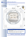
1
3 mm Beschnitt umlaufend
Megapixel
1280 x 960
software zoom
VGA (640 x 480)
10 fps Mega
-22°F to +140°F
Weatherproof
-30°C to +60°C, IP65
no heating necessary
M22M
X
Camera Manual
Part 1
IEEE 802.3af
PoE
network power
even in winter
microphone & speaker
Audio
bi-directional via IP
variable framerates
Video SIP Client
IP-Telephony
alarm notify,
cam remote control
Mega
10 fps
960 lines
Video motion
multiple windows
precision pixel-based
lip-syncronized audio
Recording
VGA
event-ringbuffer
30 cams each 30 fps
Live viewing
30 cams at 30 fps
all on one screen
Backlight
safe using CMOS
without mechanical iris
CIF
30 fps
480 lines
30 fps
288 lines
Complete integration for web and security
Current PDF File:
www.mobotix.com > Services > Manuals
Wall bracket
with cable cover
for RJ45 wall outlet
Robust
no moving parts
fiber glass housing
MOBOTIX AG • Security-Vision-Systems • Made in Germany
www.mobotix.com • [email protected] • 31.1.2007
MOBOTIX
MOBOTIX ... the new face of IP video
30 Frames/s
Security-Vision-Systems
AG
M22M Camera Manual Part 1
MOBOTIX Camera Data
Enter the data of your camera here!
Camera Model:
Camera Name:
Factory IP Address:
.
.
.
Current IP Address:
.
.
.
activated DHCP:
deactivated Admin User Name:
Admin Password:
Notes:
Technical information subject to change without notice!
No part of this manual may be reproduced by any means
without our written approval!
Copyright © MOBOTIX AG, Kaiserslautern, Germany.
Note:
MOBOTIX offers inexpensive seminars that include a workshop and
practical excercises:
Basic Seminar 2 days, Advanced Seminar 2 days.
For more information, see www.mobotix.com
© MOBOTIX AG • Security-Vision-Systems • Made in Germany
www.mobotix.com • [email protected] • 31.1.2007
1/56
M22M Camera Manual Part 1
M22M CAMERA MANUAL
PART 1
1
INTRODUCTION
6
1.1
The Concept of MOBOTIX M22M
7
1.2
Product Advantages of MOBOTIX M22M
10
1.3
Feature List
11
1.4
1.4.1
1.4.2
1.4.3
1.4.4
1.4.5
1.4.6
1.4.7
1.4.8
1.4.9
1.4.10
1.4.11
1.4.12
Important Notes
MOBOTIX M22M—Weatherproof with IP65
Password for the Administration Menu
Irreversibly Deactivating the Microphone
Starting the Camera Using the Factory IP Address
Resetting the Camera to Factory Defaults
Deactivating Event Control for Web Applications
Deactivating Text and Logo Options
Deactivating the Daily Reboot of the Camera
Browser Hints
Cleaning Instructions
Safety Notes for Operating MOBOTIX Cameras
Additional Information
14
14
14
14
14
15
15
15
15
16
16
16
17
2
MOUNTING THE CAMERA
18
2.1
Quick Start
18
2.2
Delivered Parts of the MOBOTIX M22M
18
2.3 Camera Housing and Connectors of the MOBOTIX M22M
2.3.1 Connectors
19
19
2.4
Power Supply of the MOBOTIX M22M
20
2.5
Mounting Options and Positioning
22
2.6
Dimensions of the MOBOTIX M22M
23
2.7
2.7.1
2.7.2
2.7.3
2.7.4
2.7.5
2.7.6
2.7.7
2.7.8
Mounting the MOBOTIX M22M to a Wall or Ceiling
Mounting to a Wall
Mounting to a Ceiling
Converting the Wall Mount to Ceiling Mount
Mounting the Camera over Wall Outlets
M14 Fixed Lenses
CS Mount Version
Lens Cover with Glass Pane
Changing Lenses
24
24
24
25
26
27
28
28
29
2.8
2.8.1
2.8.2
2.8.3
Wiring, Fire Prevention, Lightning and Surge Protection
Wiring
Fire Prevention
Lightning and Surge Protection
30
30
30
30
© MOBOTIX AG • Security-Vision-Systems • Made in Germany
www.mobotix.com • [email protected] • 31.1.2007
2/56
M22M Camera Manual Part 1
3
OPERATING THE CAMERA
32
3.1 General Remarks on Operating the Camera
3.1.1 Establishing the Power Supply of the Camera
3.1.2 Connecting the Camera
32
32
32
3.2
Overview of the Configuration Settings
34
3.3
3.3.1
3.3.2
3.3.3
Connecting the Camera
Power Supply Using MOBOTIX Products (Network Power Adapter)
Power Supply Using PoE Products (Power over Ethernet)
Camera Startup Sequence
36
36
37
37
3.4
3.4.1
3.4.2
3.4.3
3.4.4
3.4.5
The First Image of the Camera
Preparing the Ethernet Connection
The First Image in the Browser
Additional Information
Camera Screens in the Browser
The First Image in MxViewer
38
38
40
41
42
43
3.5
Starting the Camera With an Automatic IP Address (DHCP)
48
3.6
Starting the Camera Using the Factory IP Address
49
3.7
Drilling Template M22M (Scale 1:1)
50
APPENDIX: M22M HARDWARE FEATURES
M22M SOFTWARE FEATURES
IP65 CERTIFICATE
FCC DECLARATION OF CONFORMITY
DECLARATION OF CONFORMITY
DRILLING TEMPLATE (1:1)
Note
Download the newest version of this document as a PDF file from
www.mobotix.com under Services > Manuals.
© MOBOTIX AG • Security-Vision-Systems • Made in Germany
www.mobotix.com • [email protected] • 31.1.2007
M22M Camera Manual Part 1
SOFTWARE CAMERA MANUAL
PART 2
Note
All chapters listed in the following (4 and higher) are part of the
Camera Software Manual (Software Manual in short). The main
headings are listed below to give you an overview of the Software
Manual contents.
4
CAMERA USER INTERFACE
4.1
The First Image in the Browser
4.2
The First Image in MxViewer
4.3
The Live Screen in the Browser
4.4
The Playback Screen in the Browser
4.5
The MultiView Screen in the Browser
4.6
The PDA Screen
4.7
The Guest Screen
4.8
Browser Settings
4.9
Configuring the Softbuttons
4.10 Fast Video Streaming
4.11
Operating Multiple Cameras
5
BASIC CAMERA CONFIGURATION
5.1
Overview
5.2
Quick Installation
5.3
Connection Test
5.4
Basic Settings
5.5
Image Controls
5.6
Logos
5.7
Exposure Settings
5.8
Day & Night Modes
5.9
Managing Settings
© MOBOTIX AG • Security-Vision-Systems • Made in Germany
www.mobotix.com • [email protected] • 31.1.2007
3/56
4/56
M22M Camera Manual Part 1
6
SOFTWARE UPDATES
6.1
Overview
6.2
Preparatory Tasks
6.3
Updating the Camera Software
6.4
Update Checklist
7
EVENTS, ACTIONS AND MESSAGES
7.1
Overview
7.2
Functional Overview
7.3
Some Remarks on the Procedure
7.4
Screen Display of Event Settings in Live Image
7.5
Arming
7.6
Events
7.7
Actions and Messaging, Action and Messaging Profiles
7.8
Working with Profiles
8
RECORDING
8.1
Overview
8.2
Recording Modes
8.3
Recording Types
9
TELEPHONY FEATURES
9.1
Overview
9.2
Telephony via ISDN
9.3
Telephony via LAN and the Internet (IP Telephony)
9.4
Configuring Phone Call-In
9.5
Configuring Phone Call-Out (Phone Profiles)
9.6
Camera Phone (Listen, Speak and Intercom Modes)
9.7
Sample Configurations for IP Telephony via LAN
9.8
Sample Configurations for IP Telephony via Internet
9.9
LED Signals of the Phone Functions
10
MOBOTIX CAMERAS ON THE WEB
10.1
Overview
10.2 Displaying Cameras on the Web
© MOBOTIX AG • Security-Vision-Systems • Made in Germany
www.mobotix.com • [email protected] • 31.1.2007
M22M Camera Manual Part 1
10.3 Configuring Routers and Firewalls
10.4 Configuring DynDNS
10.5 Updating Web Pages
11
SOFTWARE INTERFACES
11.1
Overview
11.2
Accessing Live Images
11.3
Accessing the Second Image Channel
11.4
Video Streaming
11.5
The HTTP API
12
TROUBLESHOOTING
12.1
Overview
12.2 Troubleshooting Checklist
12.3 Diagnostic Tools of the Camera
12.4 Monitoring Tools of the Camera
12.5 Potential Other Problems
12.6 Additional Information
12.7 Sending Back the Camera
12.8 Warranty
APPENDIX: MODEL FEATURE LIST
Note
Download the newest version of this document as a PDF file from
www.mobotix.com under Services > Manuals.
Technical information subject to change without notice!
No part of this manual may be reproduced by any means
without our written approval!
Copyright © MOBOTIX AG, Kaiserslautern, Germany.
© MOBOTIX AG • Security-Vision-Systems • Made in Germany
www.mobotix.com • [email protected] • 31.1.2007
5/56
6/56
M22M Camera Manual Part 1
1
30 frames per second!
INTRODUCTION
The M22M camera range represents the second generation of
MOBOTIX network cameras. Now more powerful than ever, the
new compact models are capable of creating high-resolution
live video streams with high image rates. When showing VGA
video (640x480), the camera can deliver up to 30 fps (frames per
second). Even Megapixel video (1280x960) will still generate up to 10 fps. The
camera transmits realtime sound from the microphone, even in the browser.
Similar to previous MOBOTIX cameras, M22M cameras are available as SECURE,
IT, WEB and BASIC models, with WEB and BASIC models just missing the
microphone. The M22M can be fitted with one of the five M14 high-performance
lenses or with CS mount lenses (model M22M-SecureCS).
Everything integrated!
Like all other MOBOTIX cameras, the M22M models are more than “just a camera”;
the integrated software features (Secure/IT models) include a multitude of functions, such as video motion detection, long-term recording, alarm messaging
and video IP telephony. As opposed to other camera systems, buying and installing additional software on the computer is thus unnecessary. Instead of using a
web browser, you can also download the free MxViewer for Windows from
www.mobotix.com, which allows displaying multiple cameras on one monitor. Moreover, MxViewer can also process incoming
alarms from the camera and allows for comfortably searching and evaluating the alarm
video clips (including audio).
Because of the low power consumption of
only 3 Watts, the MOBOTIX M22M cameras
feature the highest operating temperature
range in the market from -30 to + 60°C (-20
to 140°F). Since MOBOTIX cameras neither
fog up nor require heating, power can be
supplied using standard PoE products. All
models come with a wall mount that covers
wall outlets and conceals the cabling.
© MOBOTIX AG • Security-Vision-Systems • Made in Germany
www.mobotix.com • [email protected] • 31.1.2007
M22M Camera Manual Part 1
1.1
7/56
The Concept of MOBOTIX M22M
High-Resolution Live Video (640x480) with up to 30 Frames/s
The second camera generation from MOBOTIX now delivers smooth live video display in VGA format with realtime audio channel, yet it keeps the network load to a
minimum (approx. 2 Mbps). Live video display thus matches the performance of
analog video systems. When recording, MOBOTIX systems easily outperform analog systems, since the MOBOTIX cameras store the same resolution and quality
with the same frame rates as in the live display. MOBOTIX technology thus allows
recording 30 cameras in continuous recording mode on one standard PC at
30 fps each, including the audio channel of the cameras.
Low Bandwidth Requirements
MOBOTIX' patent pending MxPEG streaming format allows fast live video with
audio at extremely low network loads (1 to 2 Mbps). Since the MOBOTIX camera
itself detects movements in the image, video is only transmitted if movements
occur, and when the video and audio data are stored.
Voice over IP
MOBOTIX MxPEG video streaming format includes realtime audio and intercom
features. Room surveillance with audio is possible using Internet Explorer or
MxViewer. Alarm notification on your mobile or via Internet telephony is just as
easy as event-controlled voice messages directly from the camera.
IP Telephony and Video SIP
All telephone features can be used via Internet telephony thanks to the integrated
SIP client. The SIP client allows remote-controlling the camera using the touchtone
keys and also places the alarm calls of the camera. Video SIP establishes audio/
video connections to the camera using Windows Messenger.
Long-Term Storage Included
MOBOTIX cameras have an integrated long-term storage system for Linux, Windows and Mac OS X computers. Thanks to the decentralized approach, 30 live
cameras can store images on a regular Pentium 4-class computer with 30 fps
each, including audio (depends on the operating system).
Event Storage on the Integrated CF Card (Optional)
For most applications, the MOBOTIX-installed CF card provides more than enough
storage space, since this flash card (2 GB and higher) stores the audio/video data
permanently, even after power failures. If long-term storage on a file server has
been set up, the CF card adds yet another layer of security against loss of data, as
the flash card can easily bridge longer network outages.
© MOBOTIX AG • Security-Vision-Systems • Made in Germany
www.mobotix.com • [email protected] • 31.1.2007
IP Telephony!
8/56
M22M Camera Manual Part 1
Wireless and UMTS/3G Using CF Card (Optional)
When using one of the MOBOTIX-installed Wireless or UMTS/3G CF cards for the
second CF slot of the M22M, operating the system at hard-to-reach locations
becomes easier and a lot more cost-efficient.
30 Live Cameras Using MxViewer
Download MxViewer free
of charge from
www.mobotix.com
The free MxViewer Windows client for viewing up to 30 MOBOTIX cameras with
audio now features an integrated layout editor for quick assembly of building
plans—using full drag&drop support for positioning the live camera images. Load
a floor plan as background image, drag&drop the cameras—done.
Event and Time-controlled
Just like event-controlled recording upon detecting movements in the image, the
camera can also record when the volume recorded by the microphone exceeds a
set trigger value. Using scheduled recording, time tasks can start or stop video
recording, uploading of images to a web site or sending of e-mails with video/
audio clips. Special programs control vacation times and holidays.
Remote Alert Popup
In case of an alarm, MOBOTIX cameras automatically pop up windows or activate
other functions at a remote security control center. The cameras can use network/
wireless, GSM/GPRS/UMTS (3G) or Internet connections for this purpose.
© MOBOTIX AG • Security-Vision-Systems • Made in Germany
www.mobotix.com • [email protected] • 31.1.2007
M22M Camera Manual Part 1
9/56
Power over Ethernet Integrated
Power is supplied via the network cabling using either devices that supply PoE
according to IEEE 802.3af, the MOBOTIX Network Power Adapter or the Network
Power Racks (up to 20 cameras). Since the camera's plastic housing insulates well
and does not fog up, no additional heating or fans are necessary. This is why
MOBOTIX cameras have low power requirements (3 Watts) and can be operated
every day of the year indoors as well as outdoors and why PoE can be used for
supplying power—unlike in other cameras.
No heating—PoE even in
the winter
Weatherproof
MOBOTIX cameras are certified according to IP65 and are designed for outdoor as
well as indoor usage. As the cameras do not have any moving parts, they are
extremely robust and resistant against heat or cold (-30°F to +60°C; -22°F to +
140°F).
Secure and Flexible Installation Using the SecureFlex Mount
The SecureFlex wall mount provides easy mounting of the MOBOTIX M22M to a
wall or ceiling and also allows positioning the camera into virtually any direction,
while the concealed cabling enhances the visual impression of the installation. The
mount completely covers wall outlets and allows using a defined network end
point, thus facilitating the installation.
Covers RJ45 wall outlets
and conceals the cabling
Logos, Animated or Freestyle
The Logo generator of the MOBOTIX camera allows integrating different banners
and graphics into the current camera images—with optional scheduler control.
MOBOTIX cameras are the only cameras supporting animated and transparent
graphics.
© MOBOTIX AG • Security-Vision-Systems • Made in Germany
www.mobotix.com • [email protected] • 31.1.2007
Logo generator integrated
10/56
M22M Camera Manual Part 1
1.2
Product Advantages of the MOBOTIX M22M
Product Advantages
•
•
•
•
•
•
•
•
•
•
•
•
•
•
•
•
•
•
•
•
•
•
•
•
•
MOBOTIX M22M camera models support the Power-over-Ethernet standard
IEEE 802.3af as well as the MOBOTIX power supply technology.
USB connector for MOBOTIX expansion modules.
Individual lens configuration possible.
Version CS with standard CS thread allows using CS mount and C mount
lenses (C mount with adapter ring).
Internal memory can be expanded using non-volatile CF cards (only installed
by MOBOTIX; available in future versions).
Optional Wireless or UMTS/3G functionality thanks to CF cards (only
installed by MOBOTIX; available in future versions).
High image quality with a resolution of 1.3 M pixels.
Fully browser-based—no software installation required.
Simple connection to IP network or DSL using the integrated 10/100 Ethernet
interface.
Camera configuration and playback of recorded images from any standard
browser.
Realtime audio and intercom features when camera calls using integrated
IP telephony.
Audio room surveillance using standard browser (Internet Explorer). The
camera microphone can be deactivated irreversibly.
Minimal network load thanks to innovative MxPEG compression scheme
(patent pending).
Integrated event-controlled or scheduled recording.
Live recording of up to 30 cameras with full 30 fps each on one single Pentium 4-class PC—audio included.
No limitation regarding the number of cameras and storage media; the system remains scalable.
Long-term storage of videos including audio or individual images in a ring
buffer on a standard PC or file server.
Integrated ring buffer can bridge network outages of up to 4,000 images or
6 minutes video; this can be further expanded when using the CF card
option.
Maintenance-free and weatherproof from -30 to +60°C (-22 to 140°F)
since the system has no moving parts.
Alarm notification via e-mail, SMS or phone call.
Backlight correction with predefined and customized exposure areas.
Professionally equipped with integrated sensors: Video motion detection,
microphone and speaker.
Flexibly positioned with concealed cabling and covered wall outlets thanks
to SecureFlex mount.
Free MxViewer for Windows for displaying and managing MOBOTIX cameras includes alarm management, background images, etc.
Platform-independent SDK allows developing applications; includes sample
applications (MxPlayer, MxPEG-to-MJPEG converter) and the source code.
© MOBOTIX AG • Security-Vision-Systems • Made in Germany
www.mobotix.com • [email protected] • 31.1.2007
M22M Camera Manual Part 1
1.3
11/56
Feature List
In its factory state, the MOBOTIX camera has the following main features (some
features are model-dependent):
•
•
•
•
•
•
•
•
•
•
•
•
•
•
•
•
•
•
Live images of up to 1280 x 960 pixels resolution via network, GSM, GPRS,
UMTS, wireless up to 30 fps (at 640 x 480 resolution), also adapted for PDAs.
Digital zoom with three stages (1x, 2x, 4x) and integrated panning (from 2x:
clicking in the browser image will move the visible image section in that
direction).
True software scaling using the proven and continuously improved
MOBOTIX algorithms. This results in brilliant image quality even for the
scaled-down image formats (e.g. 320 x 240).
Audio/video recording with three different recording modes: Event recording with audio, continuous recording with variable frame rate and audio as
well as event-controlled Snap Shot recording of JPEG images.
Telephony functions (SIP) for Phone Call-In and remote-controlling from
touchtone phones as well as voice phone calls from the camera for alarm
messaging purposes.
Video SIP with support for Windows Messenger and video phones.
File server tests can monitor a file server and use one or more of the defined
messaging options for error notification.
Camera tests where several cameras monitor each other, with failure notification using the defined messaging options.
Playback of recorded images/video sequences with audio in the integrated
video management system.
MultiView screen for displaying several cameras or events in one browser
window.
Event notification by e-mail, SMS (using a provider), voice notification (Phone
Call-Out), sounds and by visual means (e.g. red frame in Live image) using
two separate messaging paths.
Object tracing for analyzing the paths of objects that are moving in the
image.
Logo generator for displaying logos in the camera images with dialogs for
managing image files, image and logo profiles for controlling logo display.
Logos can have transparent areas and can be displayed partially transparent at the same time (creating a watermark effect), banner rotation and animations are also possible.
Transfer profiles for improved handling of FTP, E-Mail, phone calls, IP Notify
transfers and messages.
Time Tables for handling customized days, e.g. for holidays and vacations.
The time tables are used to control the camera's arming, image recording,
action, messaging, logo, obscure image and other features.
Speaker phone with speak, listen and intercom modes via Internet telephony (SIP) using the integrated microphone and speaker.
Phone Call-In to remotely control the camera using a touchtone phone via
Internet telephony (retrieve camera information, establish Internet connection, announcement of retrieved IP address, intercom feature, etc.).
© MOBOTIX AG • Security-Vision-Systems • Made in Germany
www.mobotix.com • [email protected] • 31.1.2007
1280 x 960 pixels
Logo generator
Speaker phone
Telephony features using
VoIP connections
(Internet telephony)
12/56
M22M Camera Manual Part 1
•
•
•
•
•
MxPEG video compression using the free MxViewer for Windows. The
ActiveX plug-in for Internet Explorer users brings all advantages of MxPEG
(including the camera's audio stream) to the browser-based user interface.
Routing allows using other network connections besides the standard route.
DynDNS client for accessing the camera using a symbolic name (e.g.
mymobotixcam.dyndns.org) although the provider is assigning a new
IP address every time the camera connects to the Internet.
Inerasable backup operating system automatically takes over when rebooting the camera after updating the system software has failed, allowing you
to restart the update process.
Enhanced startup options for the camera (obtain IP address via DHCP,
announcement of IP address and other network data, reset to factory default
settings).
Software Updates
Free software updates on
www.mobotix.com
MOBOTIX provides free software updates at regular intervals that
improve and expand the camera's functionality. To download the
update, go to www.mobotix.com and open Services. Chapter 6,
Software Update, in the Software Manual, provides more information
on the process.
© MOBOTIX AG • Security-Vision-Systems • Made in Germany
www.mobotix.com • [email protected] • 31.1.2007
M22M Camera Manual Part 1
Notes:
© MOBOTIX AG • Security-Vision-Systems • Made in Germany
www.mobotix.com • [email protected] • 31.1.2007
13/56
14/56
M22M Camera Manual Part 1
1.4 Important Notes
1.4.1 MOBOTIX M22M—Weatherproof with IP65
MOBOTIX M22M is IP65 weatherproof (absolutely dustproof, resistant against
water jets) when used with the MOBOTIX M14 lenses and mounted lens cover.
CAUTION: Only use the supplied connection cables and make sure
that the supplied rubber plugs have been fitted to seal off both
connectors. Note that the camera must never be installed without
properly installed connection cables and rubber plugs!
1.4.2 Password for the Administration Menu
Administration menu:
User: admin
Password: meinsm
The administration area of the camera (Admin Menu button) is protected by a user
name and password:
•
•
User name is admin
Password is meinsm
Enter the user name and password exactly as shown above. Note that both entries
are case-sensitive. When accessing the administration menu for the first time, the
Quick Installation wizard will help you set the most important parameters that are
relevant for your requirements. For security reasons, it is highly recommended to
change the adminstrator password after the camera has been configured
properly.
CAUTION: Make sure that you store information on user names
and passwords in a secure place. In case you loose the
administrator password and cannot access the Admin menu, the
password can only be reset at the factory. This service is not free!
1.4.3 Irreversibly Deactivating the Microphone
The microphone can be
deactivated irreversibly!
Deactivating a camera's microphone may become necessary in order to protect
the privacy of people at a workplace or for other reasons. You can permanently
and irreversibly deactivate the microphone in the Admin Menu > Loudspeaker
and Microphone dialog.
CAUTION: This deactivation is permanent and cannot be reversed
even by MOBOTIX engineers. Deactivating the microphone will
also deactivate all features that use the camera's microphone.
1.4.4 Starting the Camera Using the Factory IP Address
If the camera's IP address is not known any more, you can start the camera with its
factory IP address. Section 3.6, Starting the Camera Using the Factory IP Address,
describes this procedure in more detail.
© MOBOTIX AG • Security-Vision-Systems • Made in Germany
www.mobotix.com • [email protected] • 31.1.2007
M22M Camera Manual Part 1
15/56
1.4.5 Resetting the Camera to Factory Defaults
All settings of the MOBOTIX camera can be reset permanently to the factory default
settings. This makes sense if you have, for example, obtained a camera without
any information or you would like to reset all settings after testing the camera. In
order to perform this procedure, you need to have access to the administration
area of the camera (Admin rights). Open Admin Menu > Reset … to reset the
camera to factory defaults.
Note: In contrast to the method described in section 3.6, Starting the Camera
Using the Factory IP Address, all users (except the admin user) will be deleted
when resetting the camera to factory defaults. Likewise, the admin user's
password will be reset.
The configuration can also
be reset partially
1.4.6 Deactivating Event Control for Web Applications
In its factory state, the camera's event control and video motion detection features
are enabled. Hence, the camera stores images as soon as the video motion window (dotted frame in the image center) detects movements. In order to deactivate
event control as a whole, open Setup Menu > General Event Settings and deactivate the Arming switch. This will also remove the video motion window (dotted
frame) from the live image.
The dotted rectangle in
the live image will be
removed when
deactivating Arming
1.4.7 Deactivating Text and Logo Options
In its factory state, the MOBOTIX camera displays text information at the top and
bottom of the live image. Also, the camera displays a logo on the top right corner
of the live image. You can deactivate the status text at the bottom and the text at
the top left corner of the live image by setting Text Display in the Setup Menu >
Text & Display Settings dialog to Date & time. Setting Text Display to Off will deactivate all displayed text in the live image. In order to hide the logo in the live image,
open Admin Menu > Logo Profiles and set Logo Display to Disable.
Text and logos can be
deactivated or customized
to your liking
1.4.8 Deactivating the Daily Reboot of the Camera
In its factory state, the MOBOTIX camera will automatically reboot every morning at
3:36 am. In very rare cases, external influences (e.g. radiation in high locations) can
lead to camera malfunctions. The automatic reboot will refresh the camera's memory and will ensure proper operation without requiring any interaction on the part
of the user.
Open Admin Menu > Time Tasks and deactivate or delete the Reboot camera
task. This will prevent the camera from rebooting automatically.
© MOBOTIX AG • Security-Vision-Systems • Made in Germany
www.mobotix.com • [email protected] • 31.1.2007
Deactivating the camera
reboot
16/56
M22M Camera Manual Part 1
1.4.9 Browser Hints
Current browsers with activated JavaScript (Internet Explorer, Netscape, Mozilla,
Firefox, Safari, Konqueror, Opera, …) can show the camera's live images with their
standard settings. Text-based browsers (e.g. lynx) cannot display the user interface and are not suitable for operating the camera.
Section 4.8, Browser Settings, in the Software Manual, contains more information
on browser problems. Chapter 12, Troubleshooting, contains more information on
how to track and remove errors when operating the camera.
1.4.10 Cleaning Instructions
Cleaning the Lens Cover
•
•
•
You should clean the lens cover at regular intervals. Always use a lint-free
cotton cloth for this purpose.
If the dirt is more persistent, add a mild alcohol-free detergent without abrasive particles.
Make sure you instruct cleaning personnel on how to clean the camera.
Cleaning the Lens
•
If the lens is dirty from the installation process, clean the lens using a lint-free
cotton cloth. Make sure that the lens is still in focus after cleaning and adjust
the lens' focus if required.
1.4.11 Safety Notes for Operating MOBOTIX Cameras
Electrical surges can be induced by other electrical appliances, improper wiring,
but also from the outside (e.g. lightning strikes in phone or power lines).
MOBOTIX cameras are protected against small electrical surges by numerous
measures. These measures, however, cannot prevent the camera from being damaged when stronger electrical surges occur.
Special care should be taken when installing the camera outside of buildings as
protection against lightning also protects the building and the whole network
infrastructure.
MOBOTIX recommends having MOBOTIX cameras installed only by specialists
accustomed to installing network devices and having proper respect for the pertinent regulations regarding lightning protection and fire prevention as well as the
current technology for preventing damages from electrical surges.
Section 2.8, Wiring, Fire Prevention, Lightning and Surge Protection, contains more
information on these topics.
© MOBOTIX AG • Security-Vision-Systems • Made in Germany
www.mobotix.com • [email protected] • 31.1.2007
M22M Camera Manual Part 1
17/56
1.4.12 Additional Information
For more information on this topic, see the News and Functional Overview pages
in the online help of the camera's browser interface. Click on the yellow
icon in
the top right corner to open the camera's online help.
Camera Help
In order to get more information on the camera and its current configuration, open
the Camera Status dialog by clicking on the yellow
icon in the top right corner
of the camera's browser interface.
Camera information
Another source of information on all dialogs and parameters of the MOBOTIX camera is the Reference Manual that you can download from www.mobotix.com.
The Reference Manual consists of the MOBOTIX camera's online help in one PDF
file.
© MOBOTIX AG • Security-Vision-Systems • Made in Germany
www.mobotix.com • [email protected] • 31.1.2007
18/56
M22M Camera Manual Part 1
2
MOUNTING THE CAMERA
2.1
Quick Start
Mounting the MOBOTIX M22M generally follows these steps:
•
•
•
Checking the Delivered Parts (section 2.2)
Selecting the Power Supply (section 2.4)
Mounting the MOBOTIX M22M to a Wall or Ceiling (section 2.7)
2.2 Delivered Parts of the MOBOTIX M22M
Lens (item 1),
two lens covers (item 2)
Make sure to check the
delivered parts
Rubber plugs
Ethernet (item 5),
USB (item 6),
unused connector (item 7)
Allen wrench (item 3)
(5mm)
Ethernet cable CAT 5 (50cm/20"; item 4)
Mounting supplies are included!
Item
Count
1
1
2
1
3
1
4
1
5
1
6
1
7
1
Mounting Supplies
8
4
9
4
10
4
11
5
12
1
Part Name
Lens (installed)
Lens cover (installed), replacement lens cover
Allen wrench
Ethernet cable (installed)
Rubber plug for Ethernet connector (installed)
Rubber plug for USB connector
Rubber plug for unused connector (installed)
Dowels 8 mm
Stainless steel washers Ø 12 mm
Stainless steel wood screws with hex head 6x50 mm
Caps for covering screws
Hinged ferrite
© MOBOTIX AG • Security-Vision-Systems • Made in Germany
www.mobotix.com • [email protected] • 31.1.2007
19/56
M22M Camera Manual Part 1
2.3 Camera Housing and Connectors of the MOBOTIX M22M
The MOBOTIX M22M consists of two main components, the camera itself and the
SecureFlex wall mount. Like the M10 models, the MOBOTIX M22M also features an
integrated microphone and a speaker.
2.3.1 Connectors
•
•
10BaseT (Ethernet network)
USB connector (MOBOTIX expansion modules)
LED signals:
Wall mount
Power / Ethernet
Event / Recording
Lens cover
Microphone
2 LEDs
Lens
Speaker
Vent
Ethernet 10/100 (LAN)
USB (MOBOTIX
extension
modules)
"L" key
"R" key
2 CF slots
(only installed at
the factory)
© MOBOTIX AG • Security-Vision-Systems • Made in Germany
www.mobotix.com • [email protected] • 31.1.2007
20/56
M22M Camera Manual Part 1
2.4 Power Supply of the MOBOTIX M22M
The M22M supports the
Power-over-Ethernet
standard IEEE 802.3af
In order to reduce the amount of cabling, you should always use the Ethernet cable
(Power over Ethernet) to supply power to the camera.
For smaller installations, the MOBOTIX Network Power Adapter MX-NPA-3-RJ and
the external power unit MX-SNT-E01-30-RJ may suffice; larger installations would
benefit from one or more MOBOTIX Network Power Racks that are available for
supplying power to 4, 8 or 20 cameras (MX-NPR-4, 8 or 20). Open
shop.mobotix.com in the Accessories section to find more information on
these and other items.
Network Power Adapter
MX-NPA-3-RJ
Network Power Box
MX-NPR-4
Network Power Rack
MX-NPR-20
Since the MOBOTIX M22M supports Power over Ethernet (IEEE 802.3af), you can
also use PoE switches for supplying power.
Note
If you are using Power over Ethernet components (IEEE 802.3af) for
supplying power to the MOBOTIX M22M, these components have to
provide PoE class 0 (12.95 Watts max. power consumption of attached
device). Although the M22M only uses 3 Watts and does not require
heating even at very low temperatures, this will ensure that devices
attached to the USB port of the camera will be properly supplied.
Section 3.3, Connecting the Camera, contains more information on the possible
combinations of connections and power supply options.
© MOBOTIX AG • Security-Vision-Systems • Made in Germany
www.mobotix.com • [email protected] • 31.1.2007
M22M Camera Manual Part 1
Notes:
© MOBOTIX AG • Security-Vision-Systems • Made in Germany
www.mobotix.com • [email protected] • 31.1.2007
21/56
22/56
M22M Camera Manual Part 1
2.5 Mounting Options and Positioning
Mounting to a ceiling or
wall
Mounting to a wall
Mounting to a ceiling
Tilting (ceiling mount)
To increase the tilt of the
camera, the vertical tilt
joint can be turned
around 180
degrees (see
red arrow!)
•
•
horizontally: 360°
vertically: 90°
•
•
horizontally: 180°
vertically: 70°
Tilting (wall mount)
To increase the tilt to 70°
when mounting the camera
to a wall, the vertical tilt
joint can be
shortened (see
dotted red
line!)
Mount
© MOBOTIX AG • Security-Vision-Systems • Made in Germany
www.mobotix.com • [email protected] • 31.1.2007
M22M Camera Manual Part 1
23/56
2.6 Dimensions of the MOBOTIX M22M
The SecureFlex mount enables easy mounting of the MOBOTIX M22M models to a
wall or ceiling; the concealed cabling enhances the visual impression of the installation. The foot of the supplied wall mount is large enough to elegantly cover wall
outlets (see section 2.7.4, Mounting the Camera over Wall Outlets).
Elegantly covers wall
outlets
Check the appendix for the drilling template, which will be helpful when drilling the
holes for the supplied SecureFlex wall mount. For more detailed information on
planning,
please
download
the
MOBOTIX
Planning
Aid
from
www.mobotix.com.
Download planning aid
from www.mobotix.com
Find the drilling template
at the end of the manual
All measurements in mm!
© MOBOTIX AG • Security-Vision-Systems • Made in Germany
www.mobotix.com • [email protected] • 31.1.2007
24/56
M22M Camera Manual Part 1
2.7 Mounting the MOBOTIX M22M to a Wall or Ceiling
The mount covers RJ45
wall outlets and conceals
the cabling
The wall mount is large enough to mount the camera over a wall outlet (see section 2.7.4, Mounting the Camera over Wall Outlets).
In order to increase the tilt of the camera, turn the vertical tilt joint by 180 degrees or
shorten it.
Caution
Only use the supplied connection cables and make sure that the
supplied rubber plugs have been fitted to seal off both connectors.
Note that the camera must never be installed without properly
installed connection cables and rubber plugs!
Never use screws with countersunk heads to fasten the mount, as
these screws will destroy the mount.
2.7.1 Mounting to a Wall
Before attempting to mount the camera, make sure that you have found the
best camera position. It is important
that the camera's field of view is not
obstructed in any way.
Once the camera has been mounted to
the wall, you can fine-tune its position.
Using the integrated SecureFlex wall
mount, the camera can be turned horizontally and tilted vertically.
When mounted to a wall, the camera can be turned/tilted as follows:
•
•
horizontally: approx. 180°
vertically: approx. 70°
2.7.2 Mounting to the Ceiling
Before attempting to mount the camera
to a ceiling, make sure that you have
found the best camera position. It is
important that the camera's field of
view is not obstructed in any way.
Once the camera has been mounted to
the ceiling, you can fine-tune its position. Using the integrated SecureFlex
wall mount, the camera can be turned
horizontally and tilted vertically.
© MOBOTIX AG • Security-Vision-Systems • Made in Germany
www.mobotix.com • [email protected] • 31.1.2007
25/56
M22M Camera Manual Part 1
When mounted to a ceiling, the camera can be turned/tilted as follows:
•
•
horizontally: approx. 360°
vertically: approx 90°
2.7.3 Converting the Wall Mount to Ceiling Mount
If the camera is to be mounted to a ceiling, it is necessary to convert the SecureFlex
wall mount. Proceed as outlined in the following:
Remove cover
2
1
Mount
Pull out!
Mounting to a wall
3
4
Reseat cover
Push in until
reaching
stop!
Mounting to a ceiling
•
•
•
•
Unscrew the Allen screw in the mount, which holds the turn/tilt unit in place
(5 mm Allen wrench). Remove the Allen screw, the washer and the hex nut
from the mount and unplug the cover.
Gently pull the turn/tilt unit and the installed cable out of the vertical opening of the mount.
First insert the cable, then the turn/tilt unit into the horizontal opening of the
mount (all the way to the stop).
Press the cover into the unused opening of the mount.
© MOBOTIX AG • Security-Vision-Systems • Made in Germany
www.mobotix.com • [email protected] • 31.1.2007
Converting from wall
mount to ceiling mount in
four steps
26/56
M22M Camera Manual Part 1
•
Place the hex nut into the corresponding hole, insert the Allen screw with
washer and lightly fasten the screw so that you can still easily move the camera.
Converting the ceiling mount back to wall mount follows the steps in reverse order.
2.7.4 Mounting the Camera over Wall Outlets
Mounting the SecureFlex mount to a wall allows
covering RJ45 wall outlets (without frame) and
also allows using a defined network end point.
The wall mount has to
completely cover the wall
outlet
Wall outlet
When positioning the wall outlet, make sure that
the outlet lines up with the upper rim of the mount
later on (see figure below and the drilling template
at the end of the manual).
If no wall outlet is present, use a suitable extension
or an adapter to connect the camera to the network.
Use silicone
sealant!
Wall outlet
Foot
MOBOTIX M22M
CAT5 cable
© MOBOTIX AG • Security-Vision-Systems • Made in Germany
www.mobotix.com • [email protected] • 31.1.2007
M22M Camera Manual Part 1
27/56
When installing an above-the-wall assembly, breaking out one of the four openings
in the base of the mount will provide for properly guiding the cable into the mount.
MOBOTIX offers five different lenses from Super Wide Angle (L22)
to Tele (L135). Since the M22M is backlight-proof, these lenses do
not require an auto iris. Without the iris as a mechanical component, these glass lenses are extremely robust and maintenancefree. The standard lens for the M22M Secure and IT models is the
Super Wide Angle lens with a horizontal field of vision of
approx. 90°. Although the Super Wide Angle is a super wideangle lens, it shows very little distortion and delivers good image
quality, even when using the 4x zoom of the M22M. If a camera
with a Super Wide Angle lens has been mounted in the corner of
a room, the complete room is visible on the image.
Note
MOBOTIX lens designations do not reflect the actual focal length of the
lenses, but the focal length (Lxx mm) converted to 35 mm camera format. For example, the MOBOTIX Super Wide Angle lens has an actual
focal length of 4 mm. This would be the equivalent of 22 mm on a
35 mm camera and thus results in the MOBOTIX designation “L22” for
the Super Wide Angle lens.
Since the image sensors in the cameras have different sizes, converting to 35 mm camera as a known format provides for better comparison of the image format and the field of vision parameters of different
lenses. Another benefit is that you can easily set a 35 mm SLR camera
to the same focal length (Lxx) to obtain the same field of vision. This
approach greatly facilitates lens selection.
© MOBOTIX AG • Security-Vision-Systems • Made in Germany
www.mobotix.com • [email protected] • 31.1.2007
L22 Super Wid e Angle lens
2.7.5 M14 Fixed Lenses
28/56
M22M Camera Manual Part 1
2.7.6 CS Mount Version
M22M-SecureCS with
L24-54 Vario CS
The M22M-SecureCS is delivered with a CS mount
and a compact L24-L54 1/2" vario lens. To protect
the lens against the weather, this version comes
with a longer lens cover (43 mm inside, 53 mm
outside) with integrated glass pane and threads
for an external filter (40.5 mm x 0.5 mm). This
cover will work for lenses, which have a maximum
diameter of 36 mm and which are not longer than
43 mm.
Lens cover for Vario CS
mount lens
Because of the image sensor's size of 1/2", you can only use CS and C mount
lenses (C mount lenses with adapter ring) for 1/2" sensors or larger. Using other
lenses will produce shadows at the image borders and will reduce image sharpness. Vario lenses are not maintenance-free, they are definitely less robust and
less reliable in the long run as compared to the MOBOTIX M14 fixed lenses. This is
why the vario lenses are typically used in applications where locations are changing frequently, e.g. in industrial applications.
2.7.7 Lens Cover with Glass Pane
Lens cover for fixed
lenses with tempered
glass pane for usage in
rough environmental
conditions
As an additional accessory, a heavy-duty lens
cover with a front glass pane is available for the
M22M models. This will improve the durability of
the lens cover when used in rough conditions (at
the sea, in sand storms, etc.). This lens cover also
has a thread size that fits external filters
(40.5 mm x 0.5 mm) available from photo shops.
For example, you could install a polarization filter
to cancel out the reflections from windowpanes
or windshields.
Using this lens cover together with the L22 Super Wide Angle lens is not recommended, since this lens cover produces shadows at the image borders.
Caution
Canceling out light
reflections
Make sure that the white ring remains in the lens cover, since the ring
reduces light reflections and prevents the camera LEDs from adding
reflections to the images.
© MOBOTIX AG • Security-Vision-Systems • Made in Germany
www.mobotix.com • [email protected] • 31.1.2007
M22M Camera Manual Part 1
29/56
2.7.8 Changing Lenses
As described in section 2.7.5, M14 Fixed Lenses,
the M22M can be fitted with several MOBOTIX
lenses. Proceed as follows to change a lens:
•
•
•
•
•
•
•
•
Unmount the lens cover by turning it
counter-clockwise.
Loosen the lens' lock ring (if fitted) by turning it counter-clockwise.
Remove the lens with the lock ring by turning it counter-clockwise.
Unscrew the lock ring (if present) from the
lens you just removed and screw it onto
the new lens.
Screw the new lens with the lock ring (if present) back into the camera.
If necessary, restore the power supply of the camera.
Adjust the image sharpness according to the camera's live image on the
computer monitor.
Tighten the lock ring by turning it in clockwise direction.
This procedure is the same for the M22M-Secure-CSVario and CS/C mount
lenses, albeit without the lock ring (not installed).
© MOBOTIX AG • Security-Vision-Systems • Made in Germany
www.mobotix.com • [email protected] • 31.1.2007
Attention: Protection
class IP65 will only be
reached with mounted
lens cover
Check image sharpness!
30/56
M22M Camera Manual Part 1
2.8 Wiring, Fire Prevention, Lightning and Surge Protection
When installing the wiring inside or outside of buildings, make sure you always
adhere to the relevant regulations on wiring, fire prevention and protection against
lightning.
MOBOTIX recommends having MOBOTIX cameras installed only by specialists
accustomed to installing network devices and having proper respect for the pertinent regulations regarding lightning protection and fire prevention as well as the
current technology for preventing damages from electrical surges.
Find more information at an institution such as the International Electrotechnical
Commission (IEC, www.iec.ch) or at a manufacturer of protection devices
against lightning and electrical surges, such as Dehn (www.dehn.de).
2.8.1 Wiring
When installing the wiring, make sure you follow these guidelines:
•
Use double-shielded CAT
5/7 cables for wiring
•
Carefully follow these
instructions!
•
•
Data cable: Make sure you only use double-shielded
CAT 5/7 cable (S/STP) for Ethernet connections. Doubleshielded means that the cable as a whole is shielded
and that each twisted wire pair has its own shield.
Outdoors: Installing the camera outdoors requires special precautions and measures regarding the cables as
well as lightning and surge protection (see section
2.8.3, Lightning and Surge Protection).
Wire lengths: The cable segments must not exceed the maximum allowed
cable lengths in order to ensure proper data transfer (see section 3.3,
Connecting the Camera). Maximum cable lengths should not exceed 30 m
(33 yd.) for patch cables and 100 m (110 yd.) for installed cables.
Avoid induction: When running data cables parallel to existing regular
power lines or high-voltage wires, make sure you observe the minimum distances to the power cables.
2.8.2 Fire Prevention
When installing the power lines to the camera, make sure you always adhere to
the relevant regulations on wiring and fire prevention at the site of the installation.
2.8.3 Lightning and Surge Protection
To prevent damage from lightning and surges, make sure you follow these guidelines:
•
Lightning conductors: In areas exposed to lightning (e.g. on roofs), a distance holder (1 m/3 ft. higher, 1 m/3 ft. away from the camera) and proper
lightning conductors need to be installed in order to prevent lightning strikes
into the camera and to ensure that the energy of a lightning strike is properly
led to the ground.
© MOBOTIX AG • Security-Vision-Systems • Made in Germany
www.mobotix.com • [email protected] • 31.1.2007
M22M Camera Manual Part 1
•
Surge protection: Make sure you have installed proper protection against
electrical surges in order to prevent damage to the camera, the building and
the network infrastructure. This includes surge protectors for 19" racks, adding an uninterruptible power supply (UPS) to the MOBOTIX camera and
installing surge arresters or similar for routers, switches, servers, etc.
© MOBOTIX AG • Security-Vision-Systems • Made in Germany
www.mobotix.com • [email protected] • 31.1.2007
31/56
32/56
M22M Camera Manual Part 1
3
OPERATING THE CAMERA
3.1
General Remarks on Operating the Camera
The MOBOTIX camera does not require any software installation; all you need is
your preferred browser with JavaScript support to operate the camera. Thus, the
MOBOTIX camera is supported by all common operating systems (such as
Windows, Macintosh and Linux, ...).
3.1.1 Establishing the Power Supply of the Camera
You can choose between the following options:
PoE: see section 3.3
•
•
Netpower for 4, 8 or 20
cameras
Computer settings:
• IP address: 10.1.0.11
• Netmask: 255.0.0.0
• Gateway: none
• DNS: none
•
Power over Ethernet: Power supply using network components that are
conforming to the PoE standard IEEE 802.3af.
External power supply and Network Power Adapter (NPA): Power is supplied via the Ethernet cable from the NPA to the camera (max. length 100 m/
110 yd.).
Network cable: Using the 19" Netpower unit in a patch closet to supply
power via the network cable.
3.1.2 Connecting to the Camera
•
Ethernet interface of the camera (10/100 Mbps Ethernet): Directly from a
computer via a Network Power Adapter or a switch using a regular patch
cable; launch a browser and enter the IP address printed on the camera
label (e.g. 10.1.0.99).
If your network does not support a Class A network (i.e. 10.x.x.x), your PC
or laptop will have to be set temporarily to such a network address. For operating systems that allow multi-homing (Windows 2000, Windows XP, Linux,
Mac OS X), you can
set a second IP
address
in
the
10.x.x.x network.
User: admin
Password: meinsm
Connecting to the camera:
see section 3.4
Once a connection has
been established, click on
the Admin Menu button to
start configuring the camera. The Admin Menu controls all network settings (IP
address, netmask, DHCP,
etc.) and other options.
© MOBOTIX AG • Security-Vision-Systems • Made in Germany
www.mobotix.com • [email protected] • 31.1.2007
M22M Camera Manual Part 1
33/56
Note
After first booting the new MOBOTIX camera or after resetting to factory defaults, accessing the Administration menu in the browser
(Admin Menu button) will automatically start the Quick Installation
wizard. This is where you configure the most important camera
parameters in a step-by-step manner. If you have completed the Quick
Installation wizard at least once, the standard Administration menu will
open.
Always use Quick
Installation for initial
configuration
The configuration follows these five general steps:
Live image: http://preparkcam.mobotixserver.de
a) Establish the first connection (via the network).
b) Set the parameters for the desired connection type (Quick Installation).
c) Set the event control (events, actions and messages); see chapter 7, Events,
Actions and Messages, in the Software Manual.
d) Set the storage parameters (FTP or external ring buffer storage).
e) Store the configuration in the camera's permanent storage (flash) for rebooting.
© MOBOTIX AG • Security-Vision-Systems • Made in Germany
www.mobotix.com • [email protected] • 31.1.2007
34/56
M22M Camera Manual Part 1
3.2 Overview of the Configuration Settings
Always use Quick
Installation for initial
configuration
•
Quickly installed using the Quick Installation wizard
After first booting the camera or after resetting it to factory defaults, any
access to the administration menu (Admin Menu button) will start the Quick
Installation.
Admin Menu
This wizard will guide you through the most important settings of the camera
(configuration of the network interface, image control, etc.) and can also be
used to reset the camera to its factory settings.
It is recommended to use Admin Menu > Quick Installation later on as well,
e.g. if you would like to change or add connection methods.
•
User: admin
Password: meinsm
Administration and setup of the camera
Basic configuration tasks of the camera (e.g. passwords, interfaces, software
updates) are carried out from the administration menu (Admin Menu button), which requires the corresponding access rights (admin access level).
Open the Setup Menu (button) and find the dialogs for changing the image,
event and recording settings in the Image Control and Event Control sections. These options are also available for users belonging to the users
access level.
Setup Menu
Some of these settings can be changed using the corresponding pull-down
menus above the image on the Live screen.
•
The image settings are already optimized
The factory image settings of the MOBOTIX camera deliver excellent images
for most of the application scenarios and should not be changed; if changes
are inevitable, the adjustments should be minimal. If you would like to reset
changes without resetting the complete configuration to factory defaults, you
can use the Factory button at the bottom of the dialog to reset only this dialog's settings. If you would like to reset all image settings, you may do so
using the Manage Settings > Restore Image Settings pull-down menu
above the image on the Live screen.
Recommendation:
Always use factory image
settings!
•
All changes are only temporary
All changes to the configuration are only temporary and can thus be tested
easily. Restoring the old configuration settings can be achieved using the
Restore button in most dialogs or by running Admin Menu > Restore last
stored configuration from flash (see also section 5.9, Managing Settings, in
the Software Manual).
© MOBOTIX AG • Security-Vision-Systems • Made in Germany
www.mobotix.com • [email protected] • 31.1.2007
M22M Camera Manual Part 1
Once you have finished configuring the camera, you should always store
the settings in the camera's permanent memory. You can do so in each
dialog (clicking on Set at the bottom of each dialog will temporarily set the
changes; clicking on Close will ask you to store the complete configuration in
the camera's permanent memory) or in the Configuration section of the
administration menu (Admin Menu > Store current configuration into
flash memory).
35/56
Make sure to permanently
store changed
parameters!
The Configuration section of the administration menu provides more functions for storing, copying and managing camera settings. For additional
information on this topic, see chapter 5, Basic Camera Configuration, in the
Software Manual.
•
A camera that can keep its time
Apart from a multitude of possibilities for controlling the camera using time
(time tables, holiday and vacation rules, scheduled tasks, etc.), the camera
can also synchronize its internal clock. This allows you to keep the camera
in synch manually with a computer or fully automatic using a time server. The
camera can use both NTP time servers or time servers providing Time Protocol (RFC 868). For additional information on this topic, see section 5.4.2, Date
and Time / Time Zones and Time Servers, in the Software Manual.
•
Automatic time
synchronization using a
time server
The MOBOTIX camera can do "More"
In order to provide a better overview, some of the camera dialogs hide lessoften used options when showing the dialog. These dialogs have a More
button in the bottom right corner; click on it to display the advanced options.
If all options are displayed, the Less button appears. Clicking this button will
hide the advanced options.
Click on the More/Less
buttons to show/hide the
advanced options
© MOBOTIX AG • Security-Vision-Systems • Made in Germany
www.mobotix.com • [email protected] • 31.1.2007
36/56
M22M Camera Manual Part 1
3.3 Connecting the Camera
Make sure that you only use switches or routers that support the 10/100 Mbps
Ethernet interface of the camera and check the LED activity of the corresponding
port of the switch or router. For additional information on this topic, see section 4.11,
Operating Many Cameras, in the Software Manual.
3.3.1 Power Supply Using MOBOTIX Products (Network Power Adapter)
1) Connect the Camera connector of the Network Power Adapter (NPA) to the
NET connector of the camera.
2a) Connecting to an Ethernet switch or router:
• Connect the LAN/Power connector of the NPA to an Ethernet connector of
the switch/router or the Ethernet wall outlet.
• Plug the RJ45 connector of the external power unit into the PC/Power
connector of the NPA.
The Network Power
Adapter replaces the
crossover cable when
directly connecting to a
computer
Network Power
Adapter
2b) Connecting directly to a computer:
• Connect the PC/Power connector of the NPA to the Ethernet port of the
computer.
• Plug the RJ45 connector of the external power unit into the LAN/Power
connector of the NPA.
Network Power
Adapter
The NPA can eliminate a
crossover cable that may
be hard to obtain
© MOBOTIX AG • Security-Vision-Systems • Made in Germany
www.mobotix.com • [email protected] • 31.1.2007
M22M Camera Manual Part 1
37/56
3.3.2 Power Supply Using PoE Products (Power over Ethernet)
• Connect the NET connector of the camera to the Ethernet connector of the
switch/router. The network components need to support the PoE
standard IEEE 802.3af.
PoE IEEE 802.3af!
The network components
(switches/routers) need
to support the PoE
standard IEEE 802.3af!
Note
If you are using Power over Ethernet components (IEEE 802.3af) for
supplying power to the MOBOTIX M22M, these components have to
provide PoE class 0 (12.95 Watts max. power consumption of attached
device). Although the M22M only uses 3 Watts and does not require
heating even at very low temperatures, this will ensure that devices
attached to the USB port of the camera will be properly supplied.
3.3.3 Camera Startup Sequence
As soon as the camera's power supply has been established, the two LEDs will
show the progress of the startup sequence:
•
•
•
Booting: Once the power supply has been hooked up, the red LED lights up,
blinks for two seconds, then lights up again. The camera's boot loader
checks the hardware, unpacks and starts the operating system. All applications are verified using the checksums; in case of an error, the camera will
start using the backup operating system instead.
Waiting for key pressed: Both LEDs light up for four seconds. If you press
one of the keys labeled "R" or "L" at the back of the camera, it will execute
the corresponding function (see sections 3.5 and 3.6).
Ready: Once the application software has been started, the green LED lights
up (if it has not been switched off for this configuration). You can now access
the camera using your browser (see section 5.4.3, Configuring the LEDs and
the Signal Input, in the Software Manual).
Note
During the startup sequence or a software reboot, the LEDs will always
light up, even if they have been deactivated in Admin Menu > LED
Setup.
© MOBOTIX AG • Security-Vision-Systems • Made in Germany
www.mobotix.com • [email protected] • 31.1.2007
Start!
Key?
Ready
38/56
M22M Camera Manual Part 1
3.4 The First Image of the Camera
Once the Ethernet connection has been established (see section 3.4.1, Preparing
the Ethernet Connection), you have the following possibilities to see the first image
of the camera:
•
•
Direct access using a browser (section 3.4.2, The First Image in the Browser)
Display the camera using MxViewer (free Windows client for MOBOTIX
cameras; section 3.4.2, The First Image in MxViewer)
Open the browser-based user interface of the camera to complete the remaining
configuration tasks (see section 4.3, The Live Screen in the Browser, in the Software
Manual).
3.4.1 Preparing the Ethernet Connection
Caution:
Netmask 255.0.0.0
For this example, we will use a camera with the factory IP address 10.1.0.99.
Replace this IP address by the IP address of your camera. You will find this
address on a small sticker on the camera housing. Accessing the camera is
always the same and is independent of the connection type: simply enter the camera's IP address in the address field of the browser (see section 3.4.2, The First
Image in the Browser).
Note
Pressing the “R” key on the back of the camera will let the camera
announce the current IP address of the camera using its voice
output feature.
Open a Command Prompt
(Windows):
Start > Run, enter “cmd”,
then press [Return]
Your computer has to have a network or a wireless interface, and it should be in
the same subnet as the camera. If your network also uses IP addresses of a class
A network (e.g. 10.x.x.x, network mask 255.0.0.0), you should be able to
access the camera directly (provided no other network device uses the same IP
address).
Determine the IP address of your computer:
•
Make sure that you
replace 10.1.0.99 with the
IP address of your camera
Open a command shell
(Windows) or a console
(Linux/Unix) and enter
the following command:
Windows 2000/XP: ipconfig
Linux/UNIX: ifconfig
You will find the IP address of your Windows computer after IP address; for Linux/
UNIX computers, search for the inet address parameter of the eth0 device (the
first network interface). If your computer does not use an IP address in the
10.x.x.x range, you should change or expand the network configuration of your
computer (see below).
© MOBOTIX AG • Security-Vision-Systems • Made in Germany
www.mobotix.com • [email protected] • 31.1.2007
M22M Camera Manual Part 1
39/56
Make sure that no other network device uses the camera's IP address:
•
Open a command shell (Windows) or a console (Linux) and enter the following command:
ping <factory IP address>
If you receive an answer from another network device although the camera is not
connected, you will have to remove that device until you have reset the MOBOTIX
camera to a free IP address. We recommend using the Quick Installation wizard for
this task.
If your computer does not use an IP address in the
10.0.0.0 network (e.g. a 192.168.x.x or 172.x.x.x
network), you should add a second IP address to the
network configuration of your computer or set a new
IP address:
Windows 2000/XP:
(1) Open the Network Connections and open the
Properties of LAN Connection.
(2) Double-click Internet Protocol (TCP/IP).
(3) Click on the Alternative Configuration tab.
(4) Enter an IP address (e.g. 10.1.0.11) in the class A
network (10.x.x.x) that is unique in your network
and that is not the same as the camera's IP
address.
(5) Close all dialogs by clicking on OK.
Linux/UNIX:
(1) Open a console as root user and enter the following command:
ifconfig eth0:1 10.1.0.11
The computer now has the additional IP address 10.1.0.11, allowing it to access
the camera with its factory IP address in the 10.x.x.x network (10.1.0.99 in
this example).
© MOBOTIX AG • Security-Vision-Systems • Made in Germany
www.mobotix.com • [email protected] • 31.1.2007
The factory IP address is
printed on the sticker on
the camera housing
Example: 10.1.0.99
40/56
M22M Camera Manual Part 1
3.4.2 The First Image in the Browser
Camera access:
http://10.1.0.99
(example IP)
The factory IP address is
printed on the sticker on
the camera housing
As you have successfully started the camera for the first time, you can now access
the camera using your preferred browser
to see the live video stream and the user
interface. Internet Explorer, Mozilla, Firefox,
Safari or any other graphical browser with activated JavaScript is suitable. The
operating system is of no importance, even PDAs can be used without any problems.
Administration menu:
User name: admin
Password: meinsm
Quick Controls
Camera help,
camera status
Camera screens
Softbuttons
Logo within
the image
User interface can be
customized
Video motion windows
After entering the camera's IP address in the browser address bar (e.g. http://
10.1.0.99), you will see the Live screen of the MOBOTIX camera with its user
interface controls, such as softbuttons, buttons for the different camera screens,
pull-down menus (Quick Controls), icons for accessing the online help and the
camera status, and status information elements above and below the live image.
© MOBOTIX AG • Security-Vision-Systems • Made in Germany
www.mobotix.com • [email protected] • 31.1.2007
M22M Camera Manual Part 1
41/56
Notes
Factory Defaults: Every MOBOTIX camera has its individual factory IP
address (e.g. 10.1.0.99). You will find this address on a small
sticker on the camera housing. If you have started the camera using
DHCP or you have set the IP address manually, use the new IP address
(e.g. 192.168.0.99) instead of the factory IP address. Pressing the
“R” key on the back of the camera will prompt the camera to
announce its current IP address. For additional information on this
topic, see section 3.5, Starting the Camera With an Automatic IP
Address (DHCP).
Changing the factory IP
address: Always use
Admin Menu > Quick
Installation
Not available for Web and
Basic models
Troubleshooting: If your web browser does not show the camera's
Live screen after you have entered the IP address, you should try to
locate and resolve the error as described in chapter 12,
Troubleshooting, in the Software Manual.
MxViewer: In order to see the live image of the camera, you can also
use other applications or the integrated programming interface of the
MOBOTIX camera. MxViewer for Windows is such an application and
is provided free of charge by MOBOTIX. Besides its ability to display
fast live video of up to 30 cameras with 30 fps each on one PC,
MxViewer also allows recording and playing back video clips with
realtime audio via the network and can control pan/tilt heads using a
joystick or the mouse. Download the newest version of MxViewer from
the MOBOTIX homepage. The website also contains more information
on MOBOTIX systems as well as the MxViewer help.
3.4.3 Additional Information
For more information on this topic, see the News and Functional Overview pages
in the online help of the camera's browser interface. Click on the yellow
icon in
the top right corner to open the camera's online help.
In order to get more information on the camera and its current configuration, open
the Camera Status dialog by clicking on the yellow
icon in the top right corner of
the camera's browser interface.
Another source of information on all dialogs and parameters of the MOBOTIX camera is the Reference Manual that you can download from www.mobotix.com.
The Reference Manual consists of the MOBOTIX camera's online help in one PDF
file.
© MOBOTIX AG • Security-Vision-Systems • Made in Germany
www.mobotix.com • [email protected] • 31.1.2007
Camera Help
Camera information
42/56
M22M Camera Manual Part 1
3.4.4 Camera Screens in the Browser
By factory default, the MOBOTIX camera first shows the Live screen. You can set a
different entry page in order to prevent others from changing settings; you can
assign user names and passwords to prevent unauthorized access or you can
restrict access to the current live image only, by setting the Guest screen as entry
page.
The following screens are available:
•
Use the Administration
menu to set the camera
screen that should appear
initially when accessing
the camera IP address
http://10.1.0.99/pda
opens the PDA screen
•
•
•
•
Live/Playback/MultiView:
Click on
to open the
online help pages for the
camera screens
Guest screen: Only shows the current live image with reduced frame rate
(see section 4.7, The Guest Screen, in the Software Manual).
Live screen: Shows the current live image and allows changing the
image and event settings of the camera (see section 4.3, The Live
Screen in the Browser, in the Software Manual).
Playback screen: Shows all recorded images or video clips with
extended functions for searching and downloading images, regardless
of where the images are stored (in the internal or the external ring buffer on
a file server or PC; see section 4.4, The Playback Screen in the Browser, in the
Software Manual).
MultiView screen: Shows multiple cameras or the last events in a freely
definable layout (see section 4.5, The MultiView Screen in the Browser,
in the Software Manual).
PDA screen and PDA Event List: Both screens are optimized for PDAs with a
focus on fast data transmission with low bandwidth requirements (GSM,
GPRS) on devices with small displays (PDAs, mobile phones, sub notebooks).
The PDA Event List in particular gives a quick overview over the last events
since the live image is not transferred (see section 4.6, The PDA Screen, in the
Software Manual).
Note
Open Admin Menu > Language and Entry Page to set a different
start page when accessing the camera.
Open Admin Menu > Users and Passwords and Admin Menu >
Group Access Control Lists to set user rights and to prevent unauthorized access to certain screens (see section 5.4.1, Passwords, in the
Software Manual).
For more information on camera screens, see the online help of the camera's
browser interface. Click on the yellow
icon in the top right corner of the Live
screen to open the corresponding page of the online help.
© MOBOTIX AG • Security-Vision-Systems • Made in Germany
www.mobotix.com • [email protected] • 31.1.2007
M22M Camera Manual Part 1
43/56
3.4.5 The First Image in MxViewer
MxViewer is a free Windows application that allows displaying multiple MOBOTIX
cameras on one computer and provides alarm management functions. It can easily handle displaying 30 cameras with CIF resolution at 30 fps each in MxPEG
format on one standard PC with Intel Pentium 4 and 3 GHz.
Download MxViewer free
of charge from
www.mobotix.com
MxViewer Windows client
with background image
and freely positionable
cameras
MxViewer can do quite a bit more than simply display the video and audio data
from MOBOTIX cameras. The unique features of MxViewer and the MOBOTIX cameras create a full-featured security system: Intelligent alarm handling, manifold
possibilities of arranging the cameras on layouts (MultiView screens), ability to display cameras that are sending alarm notifications, and integrated camera management functions.
© MOBOTIX AG • Security-Vision-Systems • Made in Germany
www.mobotix.com • [email protected] • 31.1.2007
44/56
M22M Camera Manual Part 1
Installing and Starting MxViewer
Follow these steps to install MxViewer:
Download MxViewer free
of charge from
www.mobotix.com
•
•
•
•
•
Download the newest version of MxViewer as a ZIP file:
http://www.mobotix.com/Download/mxpeg.php.
Create a new folder in the Windows program files folder, e.g.:
C:\Program Files\MOBOTIX\MxViewer.
Copy the contents of the ZIP file into the folder you just created.
Create a shortcut by right-clicking on MxViewer.exe in the folder you just
created.
Copy the shortcut to the desktop.
Double-click the shortcut or the program file itself to start MxViewer.
Defining Video Sources
Defining cameras as video
sources
If you start MxViewer for the first time on a computer without having defined any
video sources before, the MxViewer Video Sources dialog will appear.
Depending on the task at hand,
select the appropriate option in
the Select video source group:
•
•
Scan
network
for
MOBOTIX
cameras
(default): Click on OK to
open the Scan Network
for MOBOTIX Cameras
dialog. The camera will
automatically scan the
subnet for MOBOTIX cameras and will display the
list of camera IP addresses.
Define video sources manually: Click on OK to open the Define Video
Sources Manually dialog and manually add the cameras.
In the Layout options group, select Show video sources in default layout. This
will prompt MxViewer to automatically generate a standard layout that comprises
all video sources (i.e. cameras) once they have been defined either automatically or
manually.
© MOBOTIX AG • Security-Vision-Systems • Made in Germany
www.mobotix.com • [email protected] • 31.1.2007
M22M Camera Manual Part 1
Automatically Searching MOBOTIX Cameras in the Same Subnet
MxViewer displays the Scan network for MOBOTIX cameras dialog:
•
•
Click on the Subnet dropdown list and select the
desired subnet.
Click on Scan to start the camera search.
If MxViewer finds only one subnet, the scanning process will start automatically.
In the first pass, MxViewer searches the selected subnet for MOBOTIX cameras and
in the second pass, MxViewer verifies if it can access the cameras.
MxViewer then highlights all cameras in the list, which have a status of OK or
Access denied:
Using the Highlighted Cameras
Click on OK to use the highlighted cameras and to include them in the default layout generated by MxViewer:
© MOBOTIX AG • Security-Vision-Systems • Made in Germany
www.mobotix.com • [email protected] • 31.1.2007
45/56
46/56
M22M Camera Manual Part 1
Automatically Searching MOBOTIX Cameras in all Subnets
Enhanced search features
Future versions of MxViewer will be able to search MOBOTIX cameras not only in
the current subnet of the computer, but also in all subnets, which can be reached
within the same physical network (e.g. not closed off by routers or other mechanisms).
This means that MxViewer can find cameras with factory IP address (e.g.
10.1.0.99 as in our sample), although the computer is in a different subnet (e.g.
172.16.0.0).
MxViewer can thus find MOBOTIX cameras automatically and without
changing the computer configuration if the camera has been plugged into the
same switch as the computer, for example.
Manually Defining MOBOTIX Cameras
Manually adding cameras
and loading recorded
video streams
If you have selected the Define video sources manually option in the MxViewer
Video Sources dialog, you can manually add the IP addresses or DNS names of
the MOBOTIX cameras.
•
Add: Adds the IP address or DNS name of the MOBOTIX camera you entered
to the list.
If possible, MxViewer shows the image of the last camera you added in the preview window. Click on OK to use all cameras in the list and to include them in the
default layout generated by MxViewer:
MxViewer can show
multiple MxPEG clips at
once!
Displaying MxPEG Video Clips
MxPEG video clips represent the files that contain the video and audio data stored
by either MOBOTIX cameras or MxViewer. These clips can be displayed in
MxViewer just like the camera images. In order to display one or more MxPEG
video clips, activate the Layout Editor, right-click the desired camera windows of
the layout one by one and select the Load Clip command.
To download sample MxPEG video clips, open the MOBOTIX website
www.mobotix.com.
© MOBOTIX AG • Security-Vision-Systems • Made in Germany
www.mobotix.com • [email protected] • 31.1.2007
M22M Camera Manual Part 1
Further Information on MxViewer
For further information on MxViewer, download the MxViewer User Manual from
www.mobotix.com:
•
•
Saving and loading MxPEG video clips
Creating and editing layouts using the Layout Editor
Note
Use MxViewer's Layout Editor to design the layout of the camera display on the screen (number of cameras, arrangement, size). The editor
supports drag&drop, MxPEG clips, and allows using building or property plans and similar graphics as a background image.
Further Information in the Software Manual
•
•
•
Section 4.3.5: JPEG, MxPEG and Audio
Section 4.3.6: Background Information on JPEG, MxPEG and Audio
Section 4.10: Fast Video Streaming
© MOBOTIX AG • Security-Vision-Systems • Made in Germany
www.mobotix.com • [email protected] • 31.1.2007
47/56
48/56
M22M Camera Manual Part 1
3.5 Starting the Camera With an Automatic IP Address (DHCP)
If your network has a DHCP server, you can start the camera with DHCP support. In
this case, the DHCP server automatically assigns an IP address.
Activate the camera
speaker!
As soon as startup has been completed, the camera automatically announces its
IP address, its network mask and its MAC address (except Web and Basic models;
speaker has to be activated). Note, that this announcement function can be deactivated (Admin Menu > Loudspeaker and Microphone).
Proceed as follows to start the camera using DHCP:
•
•
•
•
If the camera is powered on, disconnect the power supply of the camera by
unplugging the corresponding cable.
Connect the camera's power supply.
Wait until both LEDs are lighting up simultaneously for the first time.
Press the "R" key on the back of the camera within four seconds.
Press "R" key
"R" key
•
•
After about two more seconds, the camera plays a sound ("Boing, Boing").
After about another 15 seconds, the camera will announce its network data,
provided it has audio functionality.
You can now access the camera using the IP address it just announced.
Announce IP address:
Press “R” key
Notes
Simply press the "R" key once if you would like to prompt a running
camera to announce its network settings.
Caution
In case of an error, the
camera uses its last IP
address
When starting the camera with DHCP support, make sure that the network has a properly functioning DHCP server. If this is not the case, the
camera cannot obtain a valid IP address and will fall back to its last
known IP address.
© MOBOTIX AG • Security-Vision-Systems • Made in Germany
www.mobotix.com • [email protected] • 31.1.2007
49/56
M22M Camera Manual Part 1
3.6 Starting the Camera Using the Factory IP Address
Under certain circumstances, you may have to reset the camera to its factory IP
address. This could be the case if the IP address of the camera has been lost or the
camera does not react to the last known IP address.
Passwords and camera
settings will not be
changed!
Proceed as follows to start the camera using its factory IP address:
•
•
•
•
If the camera is powered on, disconnect the power supply of the camera by
unplugging the corresponding cable.
Connect the camera's power supply.
Wait until both LEDs are lighting up simultaneously for the first time.
Press the "L" key on the back of the camera within four seconds.
Press "L" key
"L" key
•
After about two more seconds, the camera plays a sound ("Boing").
The camera is now accessible again using its factory IP address (see label on
the camera housing).
Note
If you use the camera's "L" key to load the factory network configuration, this configuration is not automatically saved to flash memory.
Upon restarting the camera the next time without using the camera's
"L" key, the last stored network configuration will be used. To permanently store the new network configuration in the camera's flash memory, open Admin Menu > Store ...
Make sure you store the
factory network
configuration to the
permanent flash memory
Caution
As opposed to resetting the camera using Admin Menu > Reset
configuration to factory defaults (see section 1.4.5), the users and
passwords defined in the camera will not be reset if the camera is
being booted using the factory IP address.
© MOBOTIX AG • Security-Vision-Systems • Made in Germany
www.mobotix.com • [email protected] • 31.1.2007
Users and passwords will
not be changed!
50/56
M22M Camera Manual Part 1
3.7 Drilling Template M22M (Scale 1:1)
Find the drilling template
at the end of the manual
as a fold-out
Wall outlet at
upper rim
Note
Make sure that the drilling template is not scaled (up or down) when
printing the template.
When printing the PDF, make sure that you print two facing PDF pages
on one single A4 page in order to obtain a scale 1:1 template.
© MOBOTIX AG • Security-Vision-Systems • Made in Germany
www.mobotix.com • [email protected] • 31.1.2007
M22M Camera Manual Part 1
Notes:
© MOBOTIX AG • Security-Vision-Systems • Made in Germany
www.mobotix.com • [email protected] • 31.1.2007
51/56
M22M Hardware Features
IP65
IP65
IP65
IP65
IP65
IP65
IP65
M
M
M
M
M
M
Image Sensor
Color
Color
Color
B/W
Color
B/W
Image size
VGA
VGA
Mega
Mega
Mega
Mega
Mono (M) / Dual (D)
Resolution horizontal x vertical
Max. frame rate CIF/VGA/Mega
640x480
640x480 1280x960 1280x960 1280x960 1280x960
16/16/-
30/30/-
1
1
1
0.1
1
0.1
Sensitivity at 1 second (Lux)
0.05
0.05
0.05
0.005
0.05
0.005
Automatic night lens switch
-
-
-
-
-
-
Standard lens
L43
L22
L22
L22
L24-54
L24-54
Storage (MB)
64
64
128
128
128
128
2
32
64
64
64
64
CIF images approx.
100
2,000
4,000
4,000
4,000
4,000
VGA images approx.
50
1,250
2,500
2,500
2,500
2,500
800
800
800
800
Sensitivity at 1/60 second (Lux)
Video ring buffer (MB)
Mega images approx.
Ethernet, ISDN, USB, RS232
30/30/10 30/30/10 30/30/10 30/30/10
E /- / U /- E /- / U /- E /- / U /- E /- / U /- E /- / U /- E /- / U /-
2
2
2
2
2
-/S
M/S
M/S
M/S
M/S
M/S
External audio (Line-In/Out)
-
-
-
-
-
-
Signal Input (only via Cam-IO*)
-
2x
2x
2x
2x
2x
Signal Output (only via Cam-IO*)
-
2x
2x
2x
2x
2x
Concealed cabling
X
X
X
X
X
X
Yes (Jul 06)
Yes
Yes
Yes
No
No
CF slots (MOBOTIX extensions)
Microphone/Speaker
On stock
© MOBOTIX AG • Security-Vision-Systems • Made in Germany
www.mobotix.com • [email protected] • 31.1.2007
* Cam-IO extension box is optional accessory
Outdoor weatherproof (IP65)
M22M-Sec-Night-CS
Mx-M22M-Sec-Night-CSVario
M22M-Sec-CS
Mx-M22M-Sec-CSVario
M22M-Sec-Night
Mx-M22M-Sec-Night-N22
M22M-Sec
Mx-M22M-Sec-D22
M22M-IT
Mx-M22M-IT-D22
M22M Camera Manual Part 1
M22M-Basic
Mx-M22M-Basic-D43
52/56
53/56
Secure Models
M22M
IT Models
D10
Web Models
M10
Basic Models
M22M Camera Manual Part 1
Software Features (All Models)
Digital zoom (2x, 4x) with panning
Motion JPEG/MxPEG video streaming
X
X/X
X/X
X/X
X/X
Custom exposure windows
X
X
X
X
Video Motion Detector
X
X
X
X
Time and event control (FTP, email, logos)
X
X
X
X
Time tables with holidays
X
X
X
X
Web functionality (FTP, email)
X
X
X
X
Quad/MultiView in browser
X
X
X
X
Recording/Playback in browser
X
X
X
X
X
X
X
3
10
50
Terabyte ring buffer (Win/Lin/Mac) via network
X
X
Continuous video/audio recording, 0.2 to 30 fps
X
X
Video/audio recording (event-triggered)
X
X
Event-controlled frame rate with continuous sound
X
X
Logo generator, animations
Single image recording (pre-/post-alarm images)
* M10 delivered with L43 standard lens
X
3
Flexible event logic
X
Master/Slave arming by one camera
X
Scheduled privacy zones, several areas
X
Bidirectional audio (IP) from/to browser
X
X
Customized voice messages
X
X
VoIP telephony (Audio/Video, SIP)
X
X
Alarm calls to softphones (SIP) e.g. Xten
X
X
Remote alarm notification (via TCP/IP, IP Notify)
X
X
RS232 Data Logger/Terminal
X
X
Programming interface/HTTP API
X
X
VGA
Mega
Model Limitations
Image size
VGA
Mega
Image sensor (color / B/W)
Color
Color
Standard lens for software version
D43
D43
L22*
L22*
Audio support (Microphone/Speaker)
-/S
-/S
M/S
M/S
Color & B/W Color & B/W
© MOBOTIX AG • Security-Vision-Systems • Made in Germany
www.mobotix.com • [email protected] • 31.1.2007
54/56
M22M Camera Manual Part 1
IP65 Certificate
© MOBOTIX AG • Security-Vision-Systems • Made in Germany
www.mobotix.com • [email protected] • 31.1.2007
M22M Camera Manual Part 1
FCC Declaration of Conformity
© MOBOTIX AG • Security-Vision-Systems • Made in Germany
www.mobotix.com • [email protected] • 31.1.2007
55/56
56/56
M22M Camera Manual Part 1
Declaration of Conformity
© MOBOTIX AG • Security-Vision-Systems • Made in Germany
www.mobotix.com • [email protected] • 31.1.2007
M22M Camera Manual Part 1
MOBOTIX ... the new face of IP video
All pictures in this manual are genuine MOBOTIX camera images.
Enjoy the image quality!
Manufacturer:
CEO:
MOBOTIX AG
Luxemburger Str. 6
67657 Kaiserslautern
Dr. Ralf Hinkel
Germany
Court of Registration:
Amtsgericht Kaiserslautern
Registration Number: HRB 3724
Tel.: +49 (631) 3033-100
Fax: +49 (631) 3033-190
Tax Code: 19/650/0812/1
Tax Office: Kaiserslautern
http://www.mobotix.com
[email protected]
VAT ID: DE 202203501
Download the newest version of this document from:
http://www.mobotix.com, Services section.
Technical information subject to change without notice!
© MOBOTIX AG • Security-Vision-Systems • Made in Germany
www.mobotix.com • [email protected] • 31.1.2007
3 mm Beschnitt umlaufend
Megapixel
1280 x 960
software zoom
VGA (640 x 480)
10 fps Mega
-22°F to +140°F
Weatherproof
-30°C to +60°C, IP65
no heating necessary
M22M
X
Camera Manual
Part 1
IEEE 802.3af
PoE
network power
even in winter
microphone & speaker
Audio
bi-directional via IP
variable framerates
Video SIP Client
IP-Telephony
alarm notify,
cam remote control
Mega
Video motion
10 fps
960 lines
multiple windows
precision pixel-based
lip-syncronized audio
Recording
VGA
event-ringbuffer
30 cams each 30 fps
Live viewing
30 cams at 30 fps
all on one screen
Backlight
safe using CMOS
without mechanical iris
CIF
30 fps
480 lines
30 fps
288 lines
Complete integration for web and security
Current PDF File:
www.mobotix.com > Services > Manuals
MX-M22M-CM-EN-03
Wall bracket
with cable cover
for RJ45 wall outlet
Robust
no moving parts
fiber glass housing
MOBOTIX AG • Security-Vision-Systems • Made in Germany
www.mobotix.com • [email protected] • 31.1.2007
MOBOTIX
MOBOTIX ... the new face of IP video
30 Frames/s
Security-Vision-Systems
AG