1
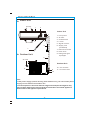
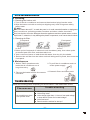
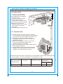
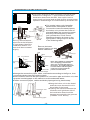
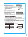
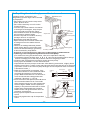
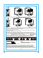
• Manufacturer’s Installation Instructions
• Current AS/NZS 3000
•All applicable local rules and regulations including local OH&S requirements
This system must be installed, commissioned and serviced by an Authorised Person.
CONTENTS
Safety Precautions
1
WEEE Warning
2
Name Of Each Part
3
Operation
4
Notices
5
Care and Maintenance
6
Troubleshooting
6
Installation Guide
8
Selection of installation location
9
Installation of the indoor unit
10
Installation of the outdoor unit
11
Pipe connection
12
Electrical connection
14
Commissioning
16
Packing list
16
Safety Precautions
Incorrect operation due to ignoring instruction will cause harm or damage.
The seriousness is classified by the following indications:
WARNING This symbol indicates the possibility of death or serious injury.
CAUTION This symbol indicates the possibility of injury or damage to properties only.
WARNING
The air conditioner must be earthed.
Incomplete grounding may result in
electric shock. Do not connect the earth
wire to the gas pipeline, water pipeline,
lightning rod, or telephone earth wire.
,
Don t pull on the power cord when removing the power plug.
The damage of pulling
power cord will cause
serious electric shock.
Minimum clearance of
1.0m to flammable
gas or liquids.
It may cause fire.
The power plug must be inserted tightly.
Otherwise, it can cause
electric shock or overheating,
even fire.
,
Don t put a finger, a rod or other object
into the air outlet or inlet.
As a fan is rotating at a high
speed, it will cause injury.
All repairs must only be carried out by
authorised service persons.
You may be hurt or cause
further malfunctions.
Stop operation and cut off the main power
in storm or hurricane. Operation
with windows opened may
cause electric shock.
Do not expose remote control or indoor
unit to water, otherwise
components could be
damaged.
g
tnin
Ligh
,
Don t touch the swinging wind vanes.
It may trap your finger
and damage the driving
parts of the wind vanes.
Isolate power at main switch when not
using the appliance for
a long period of time.
,
Don t pull out the power plug during
operating or with wet hands.
It can cause electric shock
or fire.
Cut off the
power supply
switch
Danger
,
Don t share the socket with other electric
appliance, and use the broken or
nonstandard cord. Otherwise, it
can cause electric shock even fire.
Clean the dust on the plug regularly.
Otherwise the dust mixed, humidity
will result in insulation fault even fire.
An earth leakage breaker with rated capacity
must be installed to avoid
possible electric shocks.
Children should be supervised to ensure
that they do not play with the
appliance.
This appliance is not intended for use
by persons (including children) with
reduced physical, sensory or mental
capabilities, or lack of experience and
knowledge, unless they have been
given supervision or instruction
concerning use of the appliance by a
person responsible for their safety.
When cleaning of the indoor unit case,
simply wipe over with a damp rag.
Do not use harsh cleaning
products.
-1-
CAUTION
,
1.Don t install the indoor unit in direct sunlight.
,
2.Don t block air inlet or air outlet, otherwise, the cooling or heating capacity will be
weakened, even cause system stop operating.
3.Don’t apply cold air to the body for a long time. It will deteriorate your physical
conditions and cause health problems.
4.Close the windows and doors, otherwise, the cooling or heating capacity will be
weakened.
5.If the air filter is dirty, the cooling or heating capacity will be weakened. Please
clean the air filter regularly .
6.It is prohibited to stand or put things onto the top of the outdoor unit to avoid
damage. In no case should children be allowed to sit on the outdoor unit.
7.Set a suitable temperature, especially if there are old people, children and patients
in the room. Generally, keep the temperature difference for 5℃ between the inside
and outside.
8.It is forbidden to use the air conditioner to keep precision instrumentation, artistic
production for long time and make food fresh, otherwise abnormal use will cause
damage.
9.It is forbidden to let children and the disabled use air-condition without other adult
supervision.
10.Open windows frequently after using air-condition for a long time.
11. If the equipment emissions cannot meet the technical requirement of
IEC 61000-3-3,Following Attention should be take care.
Attention!
Through poor conditions of the electrical MAINS, power supply voltage drops can
appear when starting the EQUIPMENT. This can influence other equipment (eg.
Blinking of a lamp). If the MAINS-IMPEDANCE Zmax<
OHM(See attached
nameplate), such disturbances are not expected. (In case of need, you may contact
your local supply authority for further information).
WEEE Warning
Waste Electrical and Electronic Equipment:
Do not dispose of electrical appliances as unsorted municipal
waste, use separate collection facilities.
Contact you local government for information regarding the
collection systems available.
If electrical appliances are disposed of in landfills or dumps,
hazardous substances can leak into the groundwater and get
into the food chain, damaging your health and well-being.
-2 -
Name of Each Part
★ Indoor Unit
Air inlet
1
2
Indoor Unit
3
1、Front panel
2、Air filter
3、On/Off button
Air outlet
4、Louver
5
4
5、Signal receiver
6
6、Supply cord
(if installed)
7
7、Remote controller
8、Drain hose
9、Refrigerant gas/
★ Outdoor Unit
liquid pipe
9
Air inlet
Outdoor Unit
10、Cut-off valve
11
8
11、Air outlet cover
10
Air outlet
Note:
1.If the power supply (comes directly) from outdoor unit, you can find the power
supply cord is fitted in the outdoor unit.
2. The descriptions in this user manual are(general and) text and figures may
have slightly differences to the promotion information and actual appliance.
Please refer to the appliance purchased .
-3 -
Operation
★
Remote controller operation
See "air conditioner remote controller instruction "
★
Manual operation
☆ Manual operation
When the remote controller does not work or can not be found, please follow
these steps:
1.As the unit is operating, you can press the " Auto button "
to stop operating.
2.As the unit is stopping, you can press the " Auto button "
to start operating.
☆ Adjusting air flow direction
1. Adjusting h orizontal air flow manually.
Use your hands to move the vertical airflow
vane and change the horizontal wind
direction.
! Note:
a. Adjust the horizontal air flow direction before
the air-conditioner starts. Don't insert your finger
into air intake or outlet vents when the air-conditioner is operating.
b. For appliance with auto pendulum wind function, please refer to "air
conditioner remote controller instruction " for how to adjust horizontal air flow.
2. Adjusting vertical air flow direction(up-down)
3
Refer to " air conditioner remote controller instruction " for how to adjust vertical
airflow direction through adjusting the horizontal airflow vane by remote controller.
! Note:
Adjust the vertical air flow direction by remote controller. When you adjust the
horizontal airflow vane by hand, the machine may cause problem.
Manual operation can be used temporarily in case you can not use remote
controller or its batteries are exhausted.
When the air-conditioner stops, the horizontal wind vane will close the wind
8
outlet of air conditioner.
-4-
Notices
To prevent injury and property damage, Please pay attention to these following before
operating the air conditioner.
★
Checking before operation
1.Make sure that the earth wire is connected safely and reliably.
2. Make sure the filter net is properly fixed.
3. Make sure that air outlet and inlet are not blocked.
4. Please clean the filter before starting the air-conditioner referring to page to 6
" Cleaning " for how to operate.
5. Check to see whether the outdoor install bracket is damaged. If yes, please contact
our Service center locally.
★ Safety tips
In order to use the air conditioner properly, please refer to its working temperature
range. Otherwise, indoor unit automatic protection function may be activated,
cooling or heating efficiency will be weakened.
,
The table below indicates the normal operating temperatures
>43℃(Apply to constant speed)
Cooling
Outdoor
>47℃(Apply to variable speed)
<18℃
Indoor
>30℃
Outdoor
<-7℃(Apply to constant speed)
Heating
<-12℃(Apply to variable speed)
Indoor
>30℃
The relevant Tbivalent and TOL values In standard EN 14825 are declared
as follows:
--for the average heating season
Part load Ratio
Outdoor air dry bulb(wet
bulb) temperatures (℃)
Indoor air dry bulb
Temperature (℃)
E
TOL
-10(-13)
20
F
Tbivalent
-6(-9)
20
-5-
Care and Maintenance
★
Cleaning
☆ Cleaning the indoor unit
1.Turn off the air-conditioner and remove the electrical plug from the outlet.
2. Wipe the indoor unit with a moist (not dripping wet) cloth using warm mildly
soapy water.
! Note :
Don't use water above 45℃ to wash the panel, or it could cause deformation or depigment.
Don ' t use thinner, polishing powder, benzene and other volatile chemicals.
Don't use liquid or corrosive detergent clean the appliance and don t splash water or other
liquid onto it , otherwise, it may damage the plastic components, even cause electric shock.
☆ Cleaning air filter
Front panel
Front panel
Air filter
Air filter
1.Raise up the front panel of indoor unit until it suddenly stop, then raise up the
protruded part of air filter, and then take it out.
2. Use a vacuum cleaner or wash them with water, then dry it in the shade.
3. Reinsert the air filter into the indoor unit until being entirely fixed, then close the
front panel.
★
Maintenance
1. Select " FAN " operation mode,
make the air conditioner run a
long time to dry.
2. Turn off the air conditioner and cut
off the power supply.
3. Take out the batteries from the remote
controller.
4. Clean air filters and other parts.
Troubleshooting
Check the following before requesting on service centre if the malfunction occurs.
Phenomenon
Air conditioner does
not operate at all
Trouble shooting
Has the power been shut down?
Is the wiring loose?
Is the voltage higher than 1.1 times of max rated voltage
or lower than 0.9 times of min rated voltage?
Is the fuse burnt?
Does it reach the set time for start up?
-6-
Troubleshooting
Phenomenon
Remote controller is not working
Cooling (Heating)efficiency is not
good
Indoor unit does not operate
immediately when the air
conditioner is restarted
Is the remote controller out of effective
distance to the indoor unit?
Is the battery flat?
Are there any obstructions between the
controller and the signal receptor?
Is the setting temperature suitable?
Is the air inlet or outlet obstructed?
Is air filter dirty?
Is indoor fan speed set at low speed?
Is there any heat source in your room?
Once the air conditioner is stopped,
it will not operate in approximately
3 minutes to protect itself.
There is unusual smell blowing from
the outlet after operation is started.
This is caused by the odour in the
room permeated from building
material, furniture, smoke, cleaning
products or solvents.
Sound of water flow can be heard
during cooling operation
This is caused by the refrigerant
flowing inside the unit.
Mist is emitted during cooling
operation.
Because the air of the room is cooled
down rapidly by the cold wind and it
looks like fog.
Mist is emitted during heating
operation.
This is generated due to moisture in
defrosting process.
Low noise can be heard during
operation
A low hissing sound is caused by
the refrigerant flowing.
A low squeak sound is caused by
the expansion and contraction of
plastic due to temperature.
In case the following situation, please immediately stop all operations and
isolate the power supply, then contact the service centre .
The fuse and switch trips repeatedly.
Carelessly splash water or other liquids into air conditioner.
Unusual noise can be heard during operation.
Wind blowing from the outlet smells terrible during operation.
The Run light or other display flashes rapidly and keeps flashing after electricity
re-applied.
-7-
Installation Guide
★ Guide for customer
1.Please read the instructions carefully before installation of the air-conditioner.
2.The installation should be carried out by only authorised persons.
3.Installation the air-conditioner and connecting the pipes and wires must strictly
follow the instructions
4.The wiring must be done by qualified electrician according to the electrical safety
requirements.
5.The customer should have a qualified power supply which coincides with the tag of
air conditioner, the normal voltage should be in the range of 90-110% of its rated
voltage.
6.The air conditioner must be well grounded, the switch of the main power of airconditioner must be reliably grounded.
7. If your air conditioner is not fitted with a supply cord and a plug, a n all-pole switch
must be installed in the fixed wiring in accordance with AS3000 and all local wiring
regulations.
8. If your air conditioner is permanently connected to the fixed wiring and have a
leakage current that may exceed 10 mA, leakage protector must be installed in the
fixed wiring.
9.The power supply circuit should have leakage protector and switch of which the
capacity should be more than 1.5 times of the maximum current.
★ Notices
1.The air conditioner must be installed on strong supports or surfaces.
2.The appliance shall be installed in accordance with national wiring regulations.
3.Fix the machine firmly, otherwise it will produce abnormal noise and vibration.
,
4.Install the outdoor unit in the place where it wouldn t disturb your neighbour.
5.The method of connection of the appliance to the electrical supply and inter
connection of separate components, please see the electric connection
wiring diagram label on the machine.
6.If the power supply cord is damaged, it must be replaced by the manufacture
or its service agent or a similar qualified person.
7.After installation, the isolation switch should be easily reached.
-8-
Selection of the installing position
Indoor Unit
● There is no heating and
steaming source nearby.
● No obstacles for installing
position neatly.
● Keep good air circulation.
● Convenient to adopt
measures to reduce noises.
● Do not install near doorways.
● Make sure to have the
distance between the ceiling,
wall, furniture and other
obstacles.
● 2 meters high above the floor.
★
Above
15cm
Above15cm
Outdoor Unit
● In case that you put up a canopy to protect
it from weather and sun exposure, pay attention
not to restrict air flow through condenser coil.
● Do not place animals or plants near the
installation location for the cold and hot air
out will affect them.
● Make sure to keep the distance specified
in the picture between ceiling, wall,
furniture and other obstacles.
● Run the unit away from other heating sources
and combustible gases.
Above 30cm
● The installation base and supporting frame
should be strong and secure. The machine
cm
00
e2
ov
should be on a flat and level surface.
Ab
Above 60cm
★
m
0c
e1
ov
Ab
The distance between indoor and outdoor unit should be 5 meters and pipe length can
go up to maximum 15 meters with additional refrigerant charge.
Max. Allowable
Tubing Length at
Shipment(m)
Limit of Tubing
Length(m)
Limit of Elevation Requires Amount
of Additional
Difference H(m)
Refrigerant (g/m)
CC≤12000Btu CC≥18000Btu
5
5
15
-9-
20
30
Installation of the indoor unit
●First make changes to wall and make sure that is hard
and secure. Using four "+" type screws to fasten the
installation board onto the wall. Use a spirit level to
ensure both horizontal and vertical level to ensure proper
operation and drainage of condensate tray and drain line.
●Pull out the indoor unit pipes after
detached the fixed parts on them.
Connect the interconnected pipes to
the indoor unit: point to the center of
pipe and fasten the connection screw
at first by hand and then by wrench
until you hear the " Click " sound.
Fastening direction is shown in the
right picture. Using torque is shown
in the following table.
Wall
Indoor
Outdoor
Pipe
connection
15mm
Ring
Connection pipe
Nut pipe
Spanner
Putty
70 hole
Drilling 70mm diameter
pipe hole at the left down
or right down side of the
installation board. The
hole shall slant outward
slightly.
Spanner
Remove the base
support foam in one side
before installation.
Wall
Drain pipe
Connection pipe
Base
Wall
Air-conditioner
Connection pipe
Foam
Plastic strap
Cable
Cable
Connection
pipe
Outflow tube
Cable
Installation
board
Cable
Outflow tube
Installation board
Note: The installed air-conditioner
won't be tightly pressed to the
wall if it is not arranged shown in
the picture. The outflow tube must
be in the bottom and the highest
point of it can not exceed the
position of water basin.
●Arrange the connection pipes, cable, outflow tube according to the figure , then
connect the drain pipe to the draining hole.
●Use insulation sleeve to warp the position of connection pipe and indoor unit, then
wrap the insulating tape on the sleeve to avoid condensate water.
●Fasten connection pipes, cables and drain pipe together by plastic strap.
Connection wire
Water discharge pipe
- 10 -
●Hang the indoor unit to the board
and make sure the machine is in
the middle of the board.
●Pushing the machine towards the
left down and right down side of
the installation board until the
hangers enters tightly the grooves
(it makes " click " sound)
★
Check the water discharge
1. Take off the frame the unit cover.
Take off the front frame for maintenance
according to the following steps:
● Turn perpendicular airflow direction handle
from " I " to horizontal direction.
● As shown in the picture on the right, take off
two covers from the front frame and then
unfasten two fixture screws.
● Pull the front frame towards yourself and take
it off.
In case that put the front frame back, turn the
perpendicular airflow direction handle from
" I " to horizontal, then proceed according to
the third and the second steps.
You should check whether the front frame is
firmly inside the fixture groove on the top.
2. Check the water discharge.
● Put a cup of water into groove.
● Check whether the water flow through the
water discharge hole.
Bolt Vertical airflow
direction plate
Bolt
Front frame
Pull down the front frame towards your
and take off the front frame.
Installation of the outdoor unit
● The outdoor unit must be firmly fixed to avoid falling in the strong wind.
● Install on the cement base the drawing below.
● If it will be installed at seaside or at a place high above the ground and with strong
wind, the AC should be installed against the wall to ensure the normal operation of
the fan and the backing plate should be used.
● If it will be installed in type, the structure of the mounting surface should be made
of solid steel, cement or materials with equivalent strength, and be of enough
bearing capacity. Otherwise, measures such as reinforcement, support or
vibration damping should be adopted.
Fastening locations of outdoor unit
A (mm)
B (mm)
600X250X490
390
290
760X260X540
539
287
790X280X540
522
300
800X300X690(590)
540
326
900X330X860
606
354
967X380X805
535
353
Left installation feet
Right installation feet
Air inlet
A
B
Outdoor Unit Size (mm)
Air outlet
Outdoor Unit
- 11 -
Pipe connection
● Connect the pipe to the unit: point to the
center of pipe and fasten by wrench
until it is tightly
The size of pipe Torque
fastened, the
fastening
_
6.35mm( 14 ) 18N.m
torque is in the
_3
following picture.
9.52mm( 8 ) 42N.m
_
12.7mm( 12 )
_
Indoor unit
Connection screw Pipe
55N.m
15.88mm( 85 ) 75N.m
● Pointing towards the center of pipe, fasten
the screw with strength.
● Wrench the screw in the end until you hear
the “Click” sound.
Wrench
Torque
wrench
Connection screw
Outdoor unit
Side liquid pipe
Side air pipe
Refer the direction to the picture
★
The form of pipe
Use sealing tape to
cover the small leaks
on the external ring
of the pipe
Torque wrench
Round shape
Wrap up with tape
Use sealing tape to
cover the small leaks
on the external ring of
the pipe
Pipes
Water discharge
pipe
Connection wire
Control panel cover
Round shape
Connection wire
Round in this shape to prevent water
entering the electrical parts
● Wrap up all pipe, water discharge and
connection wire from top to below.
● Cover the connection and fix them with
two plastic rings.
● Wrap up the pipes with tape alongside
the wall and fix them to the wall with
clips. These steps are usually adopted
when outdoor unit is installed below the
indoor unit.
See the picture
on the left
● In case that you want to have
additional water discharge pipe, the
end of pipe should be within certain
distance towards surface ( Terminate
drain below ground level, so it won ' t
be swayed by the wind).
● Wrap the pipes and connection wire
well from below to top.
● Wrap up the pipes that are rounded
up by the wall comers in the way
shown in the picture so it can prevent
water entering the room.
● Use clips or other fixture to fasten the
pipes to the walls.
- 12 -
★
Expelling the air in the pipes and the indoor unit
Expelling the air: humid air in the
Outdoor unit
refrigerating system might cause trouble
of compressor.
● Take off the cover from the stop valve
and T-branch valve.
● Take off the auxiliary cover from the
T-branch valve.
● Turn the stop valve rod anti-clock wise
to an angle of 90 degree, keep it open
To indoor unit
for 8 seconds and close the valve.
Liquid side
● Check whether there is air leakage at Vapor side
Gas side
all connection parts of pipes.
Stop valve(open)
● Push the top rod of T-branch valve by
hexagon wrench to expel air.
● Repeat the third and fifth steps.
Cover
● Open the stop and T-branch valve with
a hexagon wrench to make the unit
operate.
● There is no leakage allowed, please
check all the piping connection parts.
T-branch valve(open)
You must test the leakage, generally, Auxiliary cover Hexagon wrench
it can be tested by soap water.
● If the A/C is filled with R410a, make sure to discharge air and moisture
remaining in the refrigerant system with a vacuum pump.
(For method of using a manifold valve, refer to its operation manual.)
1.completely tighten the flare nuts, A, B, C, D, connect the manifold valve charge
hose to a charge port of the low-pressure valve on the gas pipe side.
2.Connect the charge hose connection to the vacuum pump.
3.Fully open the handle Lo of the manifold valve.
4.Operate the vacuum pump to evacuate. After starting evacuation, slightly loose
the flare mut of the Lo valve on the gas pipe side and check that the air is entering
(Operation noise of the vacuum pump changes and a compound meter indicates
0 instead of minus.)
Refrigerant
Indoor
5.After the evacuation is complete, fully
Outdoor
unit
unit
A
close the handle Lo of the manifold valve
Gas side
C
and stop the operation of the vacuum
Liquid side
D
pump. Make evacuation for 15 minutes or
B
Half union
more and check that compound meter
Packed valve
5
indicates -76cmHg(-1×10 Pa).
Manifold valve
6.turn the stem of the packed valve B about
Compound meter Pressure gauge
45 counterclockwise for 6~7 seconds
-76cmHg
after the gas coming out, then tighten the
flare nut again. Make suer the pressure
display in the pressure indicator is a little
Handle Hi
higher than the atmosphere pressure.
Handle Lo
Charge hose
7.Remove the charge hose from the Low
Charge hose
pressure charge hose.
Vacuum pump
8.Fully open the packed valve stems B
and A.
9.Securely tighten the cap of the packed
valve.
Low pressure valve
- 13 -
Electrical connection
The connection cables should obey MDL this table:
model
≤9000Btu
(≤2500W)
≤12000Btu
(≤3500W)
≤18000Btu
(≤5100W)
≤24000Btu
(≤7200W)
Specification of
connection cables
(mm2)
1.0
1.5
1.5
2.5
★ Indoor connection
Open the front panel, inset the connection cables from the base of the
air-conditioner, conneting to the terminal board in order (according to the graph),
using the pressing board to fasten the connection cables.
Wiring diagram of constant speed
≤12000Btu
≥24000Btu
18000Btu
Front panel
1
2
4
5
1
4
2
5
N
L
1
Bottom frame
2
3
4
5
N
L
Clip
Connection cables
Mid-frame
Connection cables
Wiring diagram of variable speed
Front panel
L
N
S
Clip
Bottom frame
Mid-frame
Connection cables
Connection cables
Open the front panel, if the indoor unit is fitted with the signal wire, please detach
the mid-frame,and insert the signal wire through the bottom frame, then connect the
signal wire quick plug of the indoor's to the outdoor's.
★ Outdoor connection
● Unscrew the screw, take off the control panel cover from the unit.
● According the connect position of indoor unit, make sure the connection cables
connet to the board of outdoor unit corresponding.
● The grounded wire connection:
1.loosen the grounded screw of electric bracket.
2.Connect the grounded wire with the grounded screw then setscrew in the " "
mark formerly.
● Fix the cable to the terminal board with clip.
● Reinstall the cover with the screw.
- 14 -
Wiring diagram of constant speed
≤5.2KW
≥7.0KW
Cover
1
2
N
Terminal board
L
Grounded wire
Connection cables
Grounded wire
Electric bracket
Cover
Connection cables
More than 5mm
Terminal board
Electric bracket
Pressing board
Wiring diagram of variable speed
More than 5mm
Terminal board
2
N
Terminal board
N
L
1
Pressing board
S
S
N
L
L
Electric bracket
Connection cables
Connection cables
Grounded wire
Electric bracket
Pressing board
Pressing board
NOTE:
※Connect the grounded wire correctly, otherwise will cause the malfunction of some
electrical componet and shock or fire indeed.
※Don't reverse the power polarity.
※Must fix the screwnail of the firmly wire, then drag the wire lightly, confirmation
whether it's firmly.
※If there is a connector, connect it directly.
The connection of connection cables of indoor unit and outdoor unit must
correspond (from the graph in down), otherwise, it could be cause shock or fire.
Wiring diagram of constant speed
Wiring diagram
Heat pump Type
Cold wind Type
of variable
speed
5.2KW
≤3.5KW
≤3.5KW
≥7.0KW
≥7.0KW
5.2KW
Terminal board of indoor unit
1
2
4
5
1
2
4
5
1
2
4
5
1
2
4
5
N
L
1
2
3
4
1
2
3
4
5
N
L
5
1
2
1
2
1
2
1
2
N
L
1
2
3
1
2
3
N
L
L
N
S
L
N
S
L
N
S
L
N
S
Terminal board of outdoor unit
Brown= Live wire
Blue= Zero line
Yellow/Green= Grounded wire
Note:
Explanation for the power cord without
plug (see below figure):
NOTE:
This manual is usually includes all the wiring mode for the different kind A/C,
please refer to the corresponding guide and instruction when wiring. We cannot
exclude the possibility that the product should be improved and caused the
change of wiring, please refer to the wiring diagram adhered on the A/C purchased.
- 15 -
Test running
● Make sure that pipes and wires are connected.
● Make sure that liquid side valve and air side valve
both are completely open.
1. The connection of power source
● Connect the wire to independent power source socket.
● Preparation of remote controller.
● Run the air-conditioner in cooling operation mode
for 30 minutes or longer.
Discharged air
2. Performance evaluation
● Test the out and in air temperature.
● Make sure whether the outlet air temperature subtract from inlet s gives more
than 10℃ 。
Packing list
● Please check the following attach carefully, if part attach isn t useful, please take
care of it.
Packing list of the indoor unit
NO.
Name
Unit
Quantity
1
Indoor unit
SET
1
2
Remote Controller
PC
1
3
Remote wall bracket
PC
1
4
AAA Battery
PC
2
5
Energy Rating Label
PC
1
6
User Manual
PC
1
Packing list of the outdoor unit
NO.
Name
Unit
Quantity
1
Outdoor Unit
SET
1
2
Vibration dampers
PC
4
3
Brass Nuts(Large)
ROLL
1
4
Brass Nuts(Small)
ROLL
1
5
Installation Manual
PC
1
6
Quick guide
PACKET
1
- 16 -