1
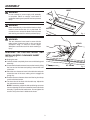
OPERATOR’S MANUAL
ZERO CLEARANCE INSERT
AC1035
For Use With Table Saws TS2400
(TS2400-0), TS2412, TS2424, and TS3612
Your zero clearance insert has been engineered and manufactured to our high standard for dependability, ease of operation,
and operator safety. When properly cared for, it will give you years of rugged, trouble-free performance.
WARNING:
To reduce the risk of injury, the user must read and understand the operator’s manual before using this product.
Thank you for buying a RIDGID product.
SAVE THIS MANUAL FOR FUTURE REFERENCE
1
RULES FOR SAFE OPERATION
n ALWAYS DISCONNECT THE SAW FROM THE POWER
SUPPLY BEFORE ASSEMBLING THIS KIT. Make sure
this switch is off when reconnecting the saw to a power
supply.
WARNING!
READ AND UNDERSTAND ALL INSTRUCTIONS.
Failure to follow all instructions listed below, may
result in electric shock, fire and/or serious personal
injury.
n MAKE SURE THE SAW BLADE OR DADO BLADE
IS NOT IN CONTACT WITH THE INSERT BEFORE
TURING THE SAW “ON.”
Safe operation of this accessory requires that you read and
understand this operator’s manual, the operator’s manual
for the table saw, and all labels affixed to the tool.
n DO NOT ATTEMPT TO TILT THE ARBOR WHILE
ANY BLADE IS IN THE INSERT. The blade may bind,
causing possible damage.
SAVE THESE INSTRUCTIONS
n A SEPARATE ZERO CLEARANCE INSERT IS
RECOMMENDED FOR EACH BLADE, dado blade, or
different set-up.
n KNOW YOUR ACCESSORY. Read the operator’s manual
carefully. Learn the product’s applications and limitations
as well as the specific potential hazards related to this
product.
n SAVE THESE INSTRUCTIONS. Refer to them frequently
and use them to instruct other users. If you loan someone
this product, also loan these instructions.
SYMBOLS
Some of the following symbols may be used on this tool. Please study them and learn their meaning. Proper interpretation
of these symbols will allow you to operate the tool better and safer.
SYMBOL
NAME
DESIGNATION/EXPLANATION
Wet Conditions Alert
Do not expose to rain or use in damp locations.
Read The Operator’s Manual
To reduce the risk of injury, user must read and understand
operator’s manual before using this product.
Eye Protection
Always wear safety goggles or safety glasses with side shields
and a full face shield when operating this product.
Safety Alert
Precautions that involve your safety.
The following signal words and meanings are intended to explain the levels of risk associated with this
product.
SYMBOL
SIGNAL
MEANING
DANGER:
Indicates an imminently hazardous situation, which, if not avoided, will
result in death or serious injury.
WARNING:
Indicates a potentially hazardous situation, which, if not avoided, could
result in death or serious injury.
CAUTION:
Indicates a potentially hazardous situation, which, if not avoided, may
result in minor or moderate injury.
CAUTION:
(Without Safety Alert Symbol) Indicates a situation that may result in
property damage.
2
ASSEMBLY
INSERT
WARNING:
Do not connect to power supply until assembly
is complete. Failure to comply could result in
accidental starting and possible serious personal
injury.
WARNING:
FLAT
HEAD SCREW
Never stand directly in line with the blade or allow
hands to come closer than 3 in. to the blade. Do
not reach over or across the blade. Failure to heed
this warning can result in serious personal injury.
Fig. 1
WARNING:
The zero clearance insert must be even with the
table surface. Inserts too high or low can let the
workpiece “snag” or catch on uneven edges.
Workpiece could twist and kick back resulting in
injury.
HEX KEY
REMOVING THE EXISTING INSERT AND
INSTALLING ZERO CLEARANCE INSERT
STRAIGHT EDGE
See Figures 1 - 2.
n Unplug the saw.
n Lower the blade completely then remove the blade guard
assembly.
n L
� oosen the flat head screw and remove the insert by lifting
the front end of the insert and pulling it toward the front
of the saw.
SET SCREWS
n Place the zero clearance insert in the table slot and push
toward the rear of the saw, making sure to engage the
spring clip.
n Position the zero clearance insert until the key slot drops
over the flat head screw.
n The insert should be flush with the table top. Adjust the
four set screws as needed.
NOTE: If necessary, adjust the side positioning set screw
found on the edge of the zero clearance insert to eliminate
side play. Tighten the flat head screw. Do not tighten the
screw to the point where it deflects the insert.
3
Fig. 2
ASSEMBLY
PREPARING THE INSERT FOR THROUGH
CUTS
PREPARING ZERO CLEARANCE INSERT FOR
NON-THROUGH CUTS
n Make sure the blade guard is properly installed and adjusted.
n Make sure the blade guard is properly installed and adjusted.
n Lower the blade completely.
n Lower the blade completely.
n Check all clearances for free blade rotation.
n Check all clearances for free blade or dado rotation.
n Plug in the saw.
n Plug in the saw.
n Turn on the saw and cautiously raise the saw blade into
the insert.
n Turn on the saw and cautiously raise the dado or blade
into the insert.
n Lower the blade.
NOTE: Use additional caution when using a dado due to
the large amount of material being “cut-away” from the
zero clearance insert. Raise dado slowly.
n The table saw and zero clearance insert are now ready
for use.
n Lower the dado or blade.
n Turn the saw “OFF” and unplug.
n The blade guard assembly is not used for “non-through”
cuts. Remove the blade guard assembly.
n The table saw and zero clearance insert are now ready for
non-through cuts. When replacing the saw blade insert,
and returning to through cuts, always replace the blade
guard assembly.
OPERATION
OPERATING TIPS
WHEN MAKING BEVEL CUTS
n Install the zero clearance insert with the blade at 90°.
Refer to “Removing the Existing Insert and Installing
Zero Clearance Insert for Through Cuts” earlier in this
manual.
WARNING:
Make sure the blade guard assembly is installed
and adjusted when making through cuts to avoid
serious possible injury.
n Lower the blade completely.
n Bevel the blade to the required setting.
n Do not use the zero clearance insert for molding
operations.
n Check for proper clearance before raising the saw
blade.
n The zero clearance insert supports the workpieces
right next to the blade to help prevent chipping and
splintering. It also prevents small pieces from becoming
wedged between the blade and the large opening in a
conventional metal table insert.
n Slowly and cautiously raise the saw blade into the zero
clearance insert.
n Never operate the saw without the proper insert
installed.
n For best results with any through cut, always adjust the
blade depth to ensure the cut is 1/8 in. - 1/4 in. higher
than the workpiece.
WARNING:
To reduce the risk of personal injury, read and
understand the Operator’s Manual for your saw
before performing any cutting operation with this
zero clearance insert.
n A separate zero clearance insert is recommended for
each blade, dado blade, or different set-up.
4
NOTES
5
OPERATOR’S MANUAL
ZERO CLEARANCE INSERT
AC1035
For Use With Table Saws TS2400
(TS2400-0), TS2412, TS2424, and TS3612
Customer Service Information:
For parts or service, contact your nearest RIDGID authorized service center. Be
sure to provide all relevant information when you call or visit. For the location of
the authorized service center nearest you, please call 1-866-539-1710 or visit us
online at www.ridgid.com.
When ordering repair parts, always give the following information:
AC1035
Model No.
983000-657
9-05
6