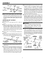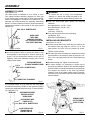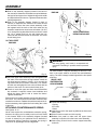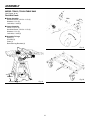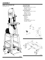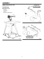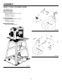
1
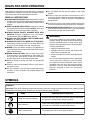
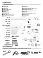
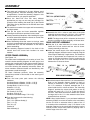
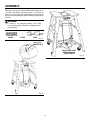
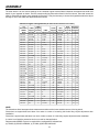
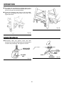
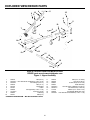
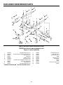
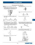
OPERATOR’S MANUAL
Herc-u-Lift PLUS
Adjustable Frame Caster Set
TM
AC9950
For Use With These Ridgid Products: TS2412/
TS2424 Table Saw, BS1400 Band Saw, RS1000
Radial Arm Saw, TP1300LS Thickness Planer,
MS1250LS Miter Saw, WL1200 Wood Lathe
and AC9910 Universal Leg Set plus selected
Craftsman Products
This Caster Set has been engineered and manufactured to our high standard for dependability, ease of operation and operator safety. When properly cared for, this product will give you years of rugged, trouble-free performance.
WARNING
To reduce the risk of injury, the user must read and understand the operator’s manual before using this product.
Thank you for buying a Ridgid product.
SAVE THIS MANUAL FOR FUTURE REFERENCE
1
TABLE OF CONTENTS
n
n
n
n
n
n
n
n
n
n
n
Introduction ...................................................................................................................................................................... 2
Rules for Safe Operation .................................................................................................................................................. 3
Symbols............................................................................................................................................................................ 4
Unpacking ........................................................................................................................................................................ 5
Loose Parts ...................................................................................................................................................................... 5
Tools Needed.................................................................................................................................................................... 5
Assembly .....................................................................................................................................................................6-19
Operation........................................................................................................................................................................ 20
Maintenance ................................................................................................................................................................... 20
Exploded View/Repair Parts......................................................................................................................................21-23
Customer Service Information........................................................................................................................................ 24
INTRODUCTION
Your Caster Set has many features for making the use of this product more pleasant and enjoyable. Safety, performance,
and dependability have been given top priority in the design of this product making it easy to maintain and operate.
2
RULES FOR SAFE OPERATION
Safe operation of this accessory requires that you read and
understand this operator's manual, the operator’s manual
for the miter saw and all labels affixed to the tool.
n Do not operate the tool with the casters in the rolling
position.
n Check to make sure tool does not move prior to use. If
tool moves, check to make sure casters disengage or, in
some applications, check for improper counterbalance
spring tension.
READ ALL INSTRUCTIONS
n KNOW YOUR ACCESSORY. Read the operator's manual
carefully. Learn the product's applications and limitations
as well as the specific potential hazards related to this
product.
n KEEP THE WORK AREA CLEAN. Cluttered work areas
and work benches invite accidents. DO NOT leave tools
or pieces of wood on the saw while operating.
n ALWAYS WEAR SAFETY GLASSES WITH SIDE
SHIELDS. Everyday eyeglasses have only impactresistant lenses; they are NOT safety glasses.
n DO NOT USE THIS PRODUCT WITH OTHER EQUIPMENT or for other purposes.
n ALWAYS GET HELP IF YOU NEED TO LIFT THE TOOL.
When lifting, hold the tool close to your body. Bend your
knees so you can lift with your legs, not your back.
n NEVER put the tool where operator's or bystander are
forced to stand with any part of their body inline with the
path of the saw blade.
n NEVER STAND ON TOOL. Serious injury could occur
if the tool tips or you accidentally hit the cutting tool.
Do not store any items above or near the stand where
anyone might climb on the stand to reach them.
n Maximum weight of power tool must not exceed 300
pounds.
n Check to make sure workstand does not rock, slide or
move prior to use.
n Put the workstand on a firm level surface where there
is plenty of room to handle and properly support the
workpiece.
n Put the tool on a firm level surface where there is plenty
of room to handle and properly support the workpiece.
n SAVE THESE INSTRUCTIONS. Refer to them frequently
and use them to instruct other users. If you loan someone
this product, also loan these instructions.
WARNING:
Some dust created by power sanding, sawing,
grinding, drilling, and other construction activities
contains chemicals known to cause cancer, birth
defects or other reproductive harm. Some examples
of these chemicals are:
• lead from lead-based paints,
• crystalline silica from bricks and cement and
other masonry products, and
• arsenic and chromium from chemically-treated
lumber.
Your risk from these exposures varies, depending
on how often you do this type of work. To reduce
your exposure to these chemicals: work in a well
ventilated area, and work with approved safety
equipment, such as those dust masks that are
specially designed to filter out microscopic
particles.
SYMBOLS
SYMBOLS
Important: Some of the following symbols may be used on this tool. Please study them and learn their meaning. Proper
interpretation of these symbols will allow you to operate the tool better and safer.
SYMBOL
NAME
DESIGNATION/EXPLANATION
Read The Operator’s Manual
To reduce the risk of injury, the user must read and understand
the operator’s manual before using this product.
Eye Protection
Always wear safety goggles or safety glasses with side shields
and a full face shield when operating this product.
Wet Conditions Alert
Do not expose to rain or use in damp locations.
3
SYMBOLS
The purpose of safety symbols is to attract your attention to possible dangers. The safety symbols, and the explanations
with them, deserve your careful attention and understanding. The safety warnings do not by themselves eliminate any
danger. The instructions or warnings they give are not substitutes for proper accident prevention measures.
SYMBOL
MEANING
DANGER: Indicates an imminently hazardous situation, which, if not avoided, will result in death or
serious injury.
WARNING: Indicates a potentially hazardous situation, which, if not avoided, could result in death
or serious injury.
CAUTION: Indicates a potentially hazardous situation, which, if not avoided, may result in minor or
moderate injury.
CAUTION: (Without Safety Alert Symbol) Indicates a situation that may result in property damage.
WARNING:
Do not attempt to use this product until you read thoroughly and understand completely the operator’s manual and
the operator manual for the tool with which this product is intended to be used. Pay close attention to the safety
rules, including Dangers, Warnings, and Cautions. If you use your product properly and only as intended, you will
enjoy years of safe, reliable service.
WARNING:
Observe all normal safety precautions related to avoid electrical shock.
WARNING:
The operation of any tool can result in foreign objects being thrown into your eyes, which can result
in severe eye damage. Before beginning operation, always wear safety goggles or safety glasses with
side shields and a full face shield when needed. We recommend Wide Vision Safety Mask for use over
eyeglasses or standard safety glasses with side shields. Always wear eye protection which is marked
to comply with ANSI Z87.1.
SAVE THESE INSTRUCTIONS
UNPACKING
NOTE: Before beginning assembly, check that all parts are
included. If you are missing any part, do not assemble this
accessory. Call 1-866-539-1710 or E-mail us at ridgid.com
to get the missing part. Sometimes small parts can get lost
in packaging material. Do not throw away any packaging
until the accessory is completely assembled and your
power tool is attached. Check packaging for missing parts
before contacting Ridgid.
4
LOOSE PARTS
The following items are included:
n
n
n
n
n
n
n
n
n
n
n
n
n
n
n
Tube, 23 in. (2)
Tube, 16-1/2 in. (1)
Tube, 13-7/8 in. (2)
Tube, 12 in. (1)
Tube, 12 in. (with holes) (1)
Tube, 11 in. (2)
Tube, 8-1/2 in. (2)
Tube, 8 in. (2)
Tube, 6-3/4 in. (2)
Tube, 6-1/2 in. (2)
Plate Assembly (1)
Casters (4)
Spring (Not Required on all tools) (1)
Chain (Not Required on all tools) (1)
U-Bolt (1)
n
n
n
n
n
n
n
n
n
n
n
n
n
n
n
Leg Bracket (4)
Leg Bracket, Band Saw (4)
Hex Head Bolt,1/4-20 x 1/2 in. (8)
Hex Head Bolt with Washer,1/4-20 x 1 1/2 in. (6)
Carriage Bolt,1/4-20 x 1/2 in. (4)
Hex Head Bolt,1/4-20 x 2 in. (4)
Hex Head Bolt with Washer,1/4-20 x 2 1/2 in. (6)
Set Screw (4)
Hex Nut with Serrated Washer, 7/16-14 (4)
Hex Nut, 5/16-18 (4)
Hex Nut with Serrated Washer, 5/16-18 (4)
Washer, 1/4 in. (8)
Lock Nut, 1/4-20 (28)
Loose Parts Pack (1)
S-Hook (3)
TUBE, 23 in.
LEG
BRACKET
PLATE
ASSEMBLY
TUBE, 16-1/2 in.
TUBE, 13-7/8 in.
TUBE, 12 in.
LEG
BRACKET
(BAND SAW)
TUBE, 12 in. (WITH HOLES)
TUBE, 11 in.
SPRING
TUBE, 8-1/2 in.
LOOSE
PARTS
BAG
CASTER
TUBE, 8 in.
TUBE, 6-3/4 in.
CHAIN
TUBE, 6-1/2 in.
HEX HD BOLT
1/4-20 X 1/2 in.
U-BOLT
SET SCREW
15/16 X 18
HEX NUT
W/ SERRATED WASHER
5/16-18
HEX HD BOLT W/ WASHER
1/4-20 X 1 1/2 in.
HEX NUT
W/ SERRATED WASHER
7/16-14
CARRIAGE BOLT
1/4-20 X 1 1/2 in.
HEX HD BOLT
1/4-20 X 2 in.
HEX NUT
5/16-18
HEX HD BOLT W/ WASHER
1/4-20 X 2 1/2 in.
WASHER
1/4 in.
LOCK NUT
1/4-20
TOOLS NEEDED
The following tools (not included) are needed for properly assembling your Herc-u-Lift Plus.
SOCKET
WRENCH
HEX WRENCH
(5/32 in.)
ADJUSTABLE WRENCH
5
WRENCHES (4)
(7/16 in., 1/2 in., 11/16 in.)
ASSEMBLY
n This caster set is designed to fit many different wood
working products. The basic assembly is the same for
all applications. Consult the assembly diagram in this
owners manual for your specific application.
n Since the Herc-U-Lift Plus has many different
applications you may not use every part provided. For
example, when installing the caster set on the TS2424
Table Saw, the leg brackets for the BS1400 band saw
are not used.
n The caster set consists of an upper and lower assembly
and leg brackets.
n First put the upper and lower assemblies together
following the instructions provided in this manual.
n Loosely assemble all fasteners. After installing the upper
and lower assemblies adjust the frames on center then
securely tighten all fasteners.
n When assembling tubes that mount to the legs, make
sure they are assembled with the large hole facing down
towards the floor. See the illustrations in this manual
before assembling.
n The assembly diagrams located in the back of the
manual show the correct hole locations for each
fastener.
TUBE, 23 in.
TUBE, 12 in. (WITHOUT HOLES)
TUBE, 11 in.
PLATE
ASSEMBLY
TUBE, 8 in.
CASTER
Fig. 1
n Assemble the 23 in. tubes to each side of the plate
assembly as shown using four 1/4-20 x 1-1/2 in. carriage
bolts and lock nuts. Loosely assemble at this time.
NOTE: The larger hole (9/16 in. diameter) at the end of
the tube, opposite the plate assembly, must face down.
REAR SUPPORT ASSEMBLY
n Slide the 12 in. tube inside the 8 in. tubes as shown.
Install the 5/16 set screws and hex nuts as shown.
Loosely assembly at this time.
n Adjust the overall length of the tubes referring to the
assembly diagram (located in back of manual) using the
“Rear Support Assembly” length shown. The dimension
shown is approximate and measured from center to
center of mounting bolt holes. Check to make sure the
center line mark on the 12 in. tube remains centered
between the 8” tubes as shown.
UPPER FRAME ASSEMBLy
See Figures 1-3.
The caster frame is adjustable to fit a variety of tools. This
manual includes assembly diagrams for each type of tool
showing the overall length of each frame member. Refer to
the diagrams in the back of the manual for your particular
tool when following the assembly instructions below. All
frame members mentioned below are identified by their
approximate overall tube length.
TUBE,
TUBE,
For Sears Craftsman products, follow the assembly
instructions provided in this manual for the same type of
RIDGID tool.
12
in.
(WITHOUT
8
REAR SUPPORT ASSEMBLY
n From the loose parts pack remove the following
hardware:
Hex Head Screw w/Washer, 1/4-20 x 1-1/2 (2)
Hex Head Screw w/Washer, 1/4-20 x 2-1/2 (2)
Carriage Bolts, 1/4-20 x 1-1/2 (4)
Washers, 1/4 in. (2)
Lock Nuts, 1/4-20 (8)
Set Screws, 5/16-18 (2)
Hex Nuts, 5/16-18 (2)
Hex Nuts w/Serrated Flange, 7/16-14 (2)
HEX
NUT
SET
SCREW
Fig. 2
n Not all tools require the use of the 11 in. tube extensions.
Refer to the assembly diagram (located in back of
manual) to determine if your particular tool requires
the 11 in. extension. If required, assemble the 11 in.
tubes inside the 23 in. tubes as shown. The “Assembly
Diagram” provides the correct hole pattern to use by
aligning the mark A, B, C, D, E or F with the edge of
the 23 in. tube. Make sure that the letters face up and
the large hole in the 11 in. tube extension faces down
towards the floor as shown.
n From the loose parts find the following:
Tube, 23 in. (2)
Tube, 12 in. (Without Holes) (1)
Tube, 11 in. (2)
Tube, 8 in. (2)
Casters (2)
Plate Assembly (1)
NOTE: Wood Lathe Model: If you purchased additional
accessory AC9951 to mount the caster to the wood lathe,
use the 37-13/16 in. extension tubes in place of the 11
in. extension tube mentioned in step 5. As shown in the
Assembly Diagram for the wood lathe (located in back of
manual), use the correct hole pattern by aligning mark A
with the edge of the 23 in. tube.
6
ASSEMBLY
n Position the rear support assembly (from step 4) under
the 23 in. tubes (from step 3) again referring to the
assembly diagram (located in back of manual). The
assembly diagram shows the correct hole pattern to
use. Attach the rear support assembly using 1/4-20 x
2-1/2 hex head screw w/washer and lock nut as shown.
Double check frame dimensions and adjust lengths as
needed.
n The 11 in. tube extension is secured either by the rear
support assembly from step 6 or by two additional
1/4-20 x 1-1/2 hex head screws w/washers. Refer
to the assembly diagram (located in back of manual)
to determine how the 11 in. extension is attached. If
required, attach the 11 in. tube extensions using 1/4-20
x 1-1/2 hex head screw w/washer, 1/4 flat washer and
1/4 lock nut as shown.
LARGE HOLE
FACES DOWN
FLANGE NUT
REAR SUPPORT
ASSEMBLY
HEX HD SCREW
W/WASHER
ALIGN ON
CENTER MARK
PLATE
ASSEMBLY
showing the overall length of each frame member. Refer to
the diagrams in the back of the manual for your particular
tool when following the assembly instructions below. All
frame members mentioned below are identified by their
approximate overall tube length.
For Sears Craftsman products, follow the assembly
instructions provided in this manual for the same type of
RIDGID tool.
n From the loose parts pack remove the following
hardware.
Hex Head Screws w/Washers, 1/4-20 x 1-1/2 (4)
Hex Head Screws w/Washers, 1/4-20 x 2-1/2 (4)
Washers, 1/4 (2)
Lock Nuts, 1/4-20 (8)
Set Screws, 5/16-18 (2)
Hex Nuts, 5/16-18 (2)
Hex Nuts w/Serrated Flange, 7/16-14 (2)
Hex Nuts w/Serrated Flange, 5/16-18 (4)
TUBE 16-1/2 in.
TUBE 13-7/8 in.
TUBE
CARRIAGE BOLT
TUBE
REAR SUPPORT ASSEMBLY
CASTER
TUBE 12 in. (WITH HOLES)
Fig. 3
CASTER
TUBE 8-1/2 in.
WARNING:
Do not assemble 11 in. tube extension beyond
“MAX” marking on top of tube. Failing to locate
extension tubes properly can damage tubes
causing unexpected tool movement. Resulting in
possible serious personal injury.
TUBE 6-3/4 in.
U-BOLT
TUBE 6-1/2 in
Fig. 4
n From the loose parts find the following:
Tube, 16-1/2 in. (1)
Tube, 13-7/8 in. (2)
Tube, 12 in. (With Holes) (1)
Tube, 8-1/2 in. (2)
Tube, 6-3/4 in. (2)
Tube, 6-1/2 in. (2)
Caster (2)
U-Bolt (1)
n Position the caster wheels in the tubes again referring
to the assembly diagram (located in back of manual).
The assembly diagram shows the correct hole pattern
to use. Location of the caster wheel is critical to assure
proper function of the unit. Double check to make sure
the caster wheel is placed in the correct hole. Fasten
each caster using the 7/16 in. flange nuts. Observe that
the nut flange is placed down against the tube.
U-BOLT SUPPORT ASSEMBLY
WARNING:
n Slide the 16-1/2 in. tube inside the 6-3/4 in. tubes as
shown. Install the 5/16 set screws and hex nuts as
shown. Loosely assembly hardware at this time.
n Adjust the overall length of the tubes referring to the
assembly diagram (located in back of manual) using the
U-bolt support assembly length shown. The dimension
shown is approximate and measured from center to
center of mounting bolt holes. Check to make sure the
center line mark on the 16-1/2 in. tube remains centered
between the 6-3/4 in. tubes as shown.
Caster wheel location is critical for proper function.
Failing to locate casters properly could cause
unexpected tool movement. Resulting in possible
serious personal injury.
LOWER ASSEMBLY
See Figures 4 and 5.
The caster frame is adjustable to fit a variety of tools. This
manual includes assembly diagrams for each type of tool
7
ASSEMBLY
TUBE, 16 1/2 in.
FLANGED
NUT
n Not all tools require the use of the 6-1/2 in. tube
extensions. Refer to the assembly diagram (located
in back of manual) to determine if your particular
tool requires the 6-1/2 in. tube extension. If required,
assemble the 6-1/2 in. tubes inside the 13-7/8 in. tubes
as shown. The assembly diagram provides the correct
hole pattern to use by aligning the mark A or B with the
edge of the 13-7/8 in. tube. Make sure that the letters
face up and the large hole in the 6-1/2 in. tube extension
faces down towards the floor as shown.
HEX NUT
SET SCREW
TUBE, 6 3/4 in.
U-BOLT
FLANGED
NUT
Fig. 5
n Place U-bolt through holes in the U-bolt support
assembly from step 3. Assemble the (4) 5/16 in. nuts on
each side of the U-bolt with the flange serration facing
the tube as shown. Adjust U-bolt to the proper length
as shown in the assembly diagram (located in back of
manual).
n Position the casters in the tubes again referring to the
assembly diagram (located in back of manual). The
assembly diagram shows the correct hole pattern to
use. Location of the caster wheel is critical to assure
proper function of the unit. Double check to make sure
the caster wheel is placed in the correct hole. Fasten
each caster using the 7/16 in. flange nuts. Make sure
that the nut flange is placed down against the tube.
CENTER SUPPORT ASSEMBLY
See Figures 6 and 7.
n Slide the 12 in. tube inside the 8-1/2 in. tubes as
shown.
WARNING:
Caster wheel location is critical for proper function.
Failing to locate casters properly could cause
unexpected tool movement. Resulting in possible
serious personal injury.
n Adjust the overall length of the tubes referring to the
assembly diagram (located in back of manual) using
the center support assembly length as shown. The
dimension shown is approximate and measured from
center to center of mounting bolt holes.Check to make
sure the center line mark on the 12 in. tube is centered
between the 8-1/2 in. tubes as shown.
n The 6-1/2 in. tube extension is secured either by the
caster or two additional 1/4-20 x 1-1/2 hex bolts. Refer
to the assembly diagram (located in back of manual) to
determine how the 6-1/2 in. extension tube is attached.
If required, attach the 6-1/2” tube extension using 1/420 x 1-1/2 in. hex head screw w/washer, 1/4 flat washer
and 1/4 in. lock nut as shown.
n Install 1/4-20 x 1-1/2 hex head screws w/washers and
lock nuts.
n Place the center support assembly under the 13-7/8 in.
tubes as shown. Observe that the large hole in the 13-7/
8 in. tube faces down toward the floor as shown. Install
TUBE, 12 in.
TUBE, 13 7/8 in.
HEX HD SCREW
W/WASHER
LOCK NUT
ALIGN ON
CENTER MARK
CENTER
SUPPORT
ASSEMBLY
FLANGE
NUT
HEX HEAD SCREW
w/WASHER
TUBE, 8 1/2 in.
Fig. 6
CASTER
1/4-20 x 2-1/2 hex head screws with washers and lock
nuts as shown.
LARGE HOLE
FACES DOWN
n Position the U-bolt support assembly (from step 3) under
the 13-7/8 in. tubes again referring to the assembly
diagram (located in back of manual). The assembly
diagram shows the correct hole pattern to use. Attach
the U-bolt support assembly using 1/4-20 x 2-1/2 hex
head screw w/washer and lock nut as shown. Double
check frame dimension and adjust lengths as needed.
8
U-BOLT
SUPPORT
ASSEMBLY
TUBE, 6 1/2 in.
Fig. 7
ASSEMBLY
ASSEMBLY TO LEGS
WARNING:
See Figures 8-10.
The caster frame is adjustable to fit a variety of tools.
This manual includes assembly diagrams for each type
of tool showing the overall length of each frame member.
Refer to the diagrams in the back of the manual for your
particular tool when following the assembly instructions
below. For Sears Craftsman products, follow the assembly
instructions provided in this manual for the same type of
RIDGID tool.
DRILL 9/32 in. DIAMETER HOLE
3 1/8 in.
To reduce the risk of injury, from unexpected
starting of a power tool already mounted to the
legset, unplug the tool before attaching caster set.
n From the loose parts pack remove the following
hardware:
Hex Head Screws, 1/4-20 x 1/2 (8)
Hex Head Screws, 1/4-20 x 2 (4)
Washers, 1/4 (4)
Lock Nuts, 1/4-20 (12)
n From the loose parts remove the following:
Leg Bracket, (4) or
Band Saw Leg Brackets (4)
RADIAL SAWS
TABLE SAWS
UNIVERSAL LEG STAND
(ALL TOOLS WITH LEVELING
FOOT EXCEPT BAND SAW)
1 1/2 in.
INSTALLING LEG BRACKETS
See Figures 11 and 12.
n All tools except band saw; install the four brackets on
the inside of each leg using two 1/4-20 x 1/2 in. hex
head screws and lock nuts per bracket as shown.
Tighten screws securely.
Fig. 8
n On some models in order to mount the caster, it may
be necessary to drill two 9/32 in. holes in each leg as
shown. The hole dimensions depend on the type of
legstand, either with adjustable leveling foot or fixed
rubber pad as shown.
n For band saw; remove leveling feet, install the four band
saw brackets on the outside of each leg using one 1/420 x 1/2 in. hex head screw and lock nut per bracket as
shown.
n Reinstall leveling feet. Tighten screws securely.
MS1250LS MITER SAW
TP1300LS THICKNESS PLANER
n On certain models it is necessary to remove one of
the lower leg stiffeners. Refer to the assembly diagram
(located in back of manual) to determine if your particular
tool requires the removal of the lower leg stiffener
located in front of the caster release pedal. If required,
remove the two truss head screws from the stiffener and
remove stiffener.
1 1/2 in.
DRILL 9/32 in. DIAMETER HOLE
3 1/2 in.
REMOVE FOOT TO MEASURE
Fig. 9
If the AC9950 caster is to be used with the wood lathe,
an additional accessory AC9951 is also required. AC9951
contains two additional extension tubes. To order AC9951,
all 1-866-539-1710.
BAND SAW
SOME MODELS REQUIRE
DRILLING HOLES AS
SHOWN ABOVE
REMOVE LOWER
LEG STIFFENER IN
FRONT OF PEDAL
ALIGN BRACKET WITH
CORNER OF LEG
DRILL 9/32 in. DIAMETER HOLE
PLACE LEVELING FOOT
THROUGH HOLE IN
BRACKET AND LEG
Fig. 10
Fig. 11
9
ASSEMBLY
n Refer to the assembly diagram (located in the back of
the manual) to determine the distance required between
the legs for each type of tool. Adjust the legs to the width
and depth dimensions shown. Tighten all fasteners after
making adjusments.
n Refer to the assembly diagram (located in back of
manual) to determine the direction the caster should
be mounted. Place the lower frame assembly under
the legstand with the ends of the tube under the leg
brackets. Install the hex head screw w/washer (1/4-20 x
2 in.) through the leg bracket and tube as shown. Install
the 1/4 in. washer and lock nut and tighten the lock
nuts until flush with the bottom of the screw. The screw
should freely pivot.
BAND SAW
CENTER FRAMES EQUAL
DISTANCE ON EACH SIDE
ALL TOOLS EXCEPT
BAND SAW
Fig. 13
WARNING:
Not using spring could result in unexpected tool
movement. Resulting in possible serious personal
injury.
CENTER FRAMES EQUAL
DISTANCE ON EACH SIDE
On some models, it may be necessary to drill one 1/4 in.
hole in the upper stiffener to secure the counterbalance
spring. The hole is always located opposite the foot pedal
as shown.
Fig. 12
n Place the upper frame assembly under the legstand with
the ends of the tube under the leg brackets. Install the
hex head screw w/washer (1/4-20 x 2 in.) through the
leg bracket and tube as shown. Install the 1/4 in. washer
and lock nut and tighten the lock nuts until flush with the
bottom of the screw. The screw should freely pivot.
n Check to insure the upper and lower frame assemblies
are centered. If required, loosen frame hardware and
adjust the frames side to side to center the frames.
Tighten all hardware.
Press down on the plate assembly and check alignment of
the U-bolt. The U-bolt should be centered within the latch
mechanism as shown. Release the pedal and adjust the Ubolt as necessary, then tighten the nuts holding the U-bolt
to the tube.
ADJUST U-BOLT
CENTERED WITHIN
LATCH MECHANISM
U-BOLT
LATCH
MECHANISM
Fig. 14
n Locate the following:
1 Spring
3 S-hooks
1Chain
n Insert the s-hook in the upper leg stiffener as shown and
attach chain.
n Place S-hooks on each end of the spring.
n Release foot pedal to make sure the upper frame
assembly is unlocked from the lower frame assembly.
n Insert spring S-hook into the center support assembly
as shown.
ATTACHING COUNTERBALANCE SPRING
See Figures 13-17.
Not all units require the counterbalance extension spring,
however, the spring can be safely used on all tools listed
in this manual. Refer to the assembly diagram (located
in back of manual) for your particular tool to determine if
the extension spring is required. In general, the spring is
required on all lightweight tools and legstands.
10
ASSEMBLY
Stretch the spring to an approximate overall length of 1315 inches, and attach the spring s-hook to the chain as
shown. The spring should counterbalance the weight of
the caster frame so that the caster wheels just barely touch
the floor.
WARNING:
If spring is not adjusted properly, tool could
move unexpectedly. Resulting in possible serious
personal injury.
SPRING
S-HOOK
CHAIN
3/8 in.
Fig. 15
DRILL 1/4 in.
DIAMETER HOLE
UNLOCK PEDAL LATCH
BEFORE ADJUSTING
SPRING TENSION
Fig. 17
Fig. 16
11
ASSEMBLY
MODEL TS2412, TS2424 TABLE SAW
See Figures 18-20.
Parts Not Used:
n Upper Assembly
Hex Head Screw, 1/4-20 x 1-1/2 (2)
Washers, 1/4 in. (2)
Lock Nuts, 1/4-20 (2)
16 in.
6 in.
3 5/1
n Lower Assembly
Tubes, 6-1/2 in. (2)
Hex Head Screw, 1/4-20 x 1-1/2 (2)
Washers, 1/4 in. (2)
Lock Nuts, 1/4-20 (2)
n Assembly To Legs
Spring (1)
S-Hooks (3)
Chain (1)
Band Saw Leg Brackets (4)
"B"
Fig. 19
18
19
1/8
in.
in.
n.
6i
1
/1
13
28 1/4 in.
24 in.
Fig. 20
Fig. 18
12
ASSEMBLY
MODEL BS1400 BAND SAW
Parts Not Used:
See Figures 21-23.
n Upper Assembly
Hex Head Screw, 1/4-20 x 1 1/2 (2)
Washers, 1/4 in. (2)
Lock Nuts, 1/4-20 (2)
n Lower Assembly
Hex Head Screw, 1/4-20 x 1 1/2 (2)
Tubes, 6 1/2 in. (2)
Washers, 1/4 in. (2)
Lock Nuts, 1/4-20 (2)
n Assembly To Legs
Spring (1)
S-Hooks (3)
Chain (1)
Leg Brackets (4)
Hex Head Screw, 1/4-20 x 1/2 (4)
Lock Nuts, 1/4-20 (4)
15
in.
1 1/2
in.
"A"
Fig. 22
16
17
1
16
13/
5/1
in.
6i
n.
in.
26 1/2 in.
17 in.
Fig. 23
Fig. 21
13
ASSEMBLY
MODEL RS1000 RADIAL SAW
EXTENSION TUBE
SECURED WITH 1/4-20 X 1
1/2 in. HEX HEAD SCREW
WASHER AND LOCKNUT
See Figures 24-26.
Parts Not Used:
n Assembly To Legs
Spring (1)
S-Hooks (3)
Chain (1)
Band Saw Leg Brackets (4)
18
5/8
in.
7 11/16
in.
"E"
Fig. 25
6 in.
3 5/1
22
20
13/
16
in.
in.
"B"
EXTENSION TUBE
SECURED WITH 1/4-20 X 1
1/2 in. HEX HEAD SCREW
WASHER AND LOCKNUT
35 in.
31 in.
Fig. 24
14
Fig. 26
ASSEMBLY
MODEL TP1300LS THICKNESS PLANER
See Figures 27-29.
Parts Not Used:
14
n Upper Assembly
Hex Head Screw, 1/4-20 x 1-1/2 (2)
Washers, 1/4 in. (2)
Lock Nuts, 1/4-20 (2)
5/8
/16
in.
4 13
in.
n Lower Assembly
Hex Head Screw, 1/4-20 x 1-1/2 (2)
Washers, 1/4 in. (2)
Lock Nuts, 1/4-20 (2)
n Assembly To Legs
Band Saw Leg Brackets (4)
"C"
Fig. 28
18
/2
11
18
in.
6
3/1
in.
in.
in.
11
"A"
Fig. 29
22 in.
31 1/4 in.
Fig. 27
15
ASSEMBLY
MODEL MS1250LS MITER SAW
See Figures 30-32.
Parts Not used:
17
n Upper Assembly
Hex Head Screw, 1/4-20 x 1-1/2 (2)
Washers, 1/4 in. (2)
Lock Nuts, 1/4-20 (2)
11/
16
n.
/16 i
in.
8 13
n Assembly To Legs
Band Saw Leg Brackets (4)
"F"
Fig. 31
3 5/16 in.
20
21
/8
13
1/4
in.
in.
in.
"B"
EXTENSION TUBE SECURED
WITH 1/4-20 X 1 1/2 in. HEX
HEAD SCREW WASHER AND
LOCKNUT
27 in.
37 1/4 in.
Fig. 30
16
Fig. 32
ASSEMBLY
MODEL WL1200 WOOD LATHE
See Figures 33-35.
Parts Not Used:
21
n Upper Assembly *
Tubes, 11 in. (2)
1/8
in.
n.
32 i
n Lower Assembly
Hex Head Screw, 1/4-20 x 1-1/2 (2)
Washers, 1/4 in. (2)
Lock Nuts, 1/4-20 (2)
*AC9951 Tubes required (purchase separately)
n Assembly To Legs
Band Saw Leg Brackets (4)
"A"
Fig. 34
.
1 1/2 in
20
11
5/1
16
5/8
in.
in.
6i
n.
"A"
58 in.
Fig. 35
30 1/4 in.
Fig. 33
17
ASSEMBLY
MODEL AC9910 UNIVERSAL LEGSET
REAR EXTENSION TUBE 11 in.
(SECURED BY REAR SUPPORT
ASSEMBLY OR CASTER)
See Figures 36-38.
Parts Not Used:
n Upper Assembly
Hex Head Screws, 1/4-20 x 1-1/2 (2)
Washers, 1/4 in. (2)
Lock nuts, 1/4-20 (2)
POSITION A, B, C, OR
RE
D SEE CHART
AR
AS SUP
SE PO
in.
MB RT
3 13/16
LY
n Lower Assembly
Hex Head Screws, 1/4-20 x 1-1/2 (2)
Washers, 1/4 in. (2)
Lock nuts, 1/4-20 (2)
n Assembly To Legs
Band Saw Leg Brackets (4)
5
4
3 2
1
Fig. 37
CE
NT
/
n.
16 i
3 13
U-B
OLT
ER
SU
PP
OR
TA
SS
SU
PPO
RT
A
T
OL ENT
U-B STM
JU
AD
POSITION A OR B
SEE CHART
FRONT EXTENSION
TUBE 6 1/2 in.
SSE
EM
BLY
MB
LY
3
2
1
U BOLT SUPPORT
LOCATION - HOLE
NUMBER SEE CHART
Fig. 38
H
DEPT
WIDTH
Fig. 36
18
ASSEMBLY
The table below is for the various settings of the Universal Legset model AC9910. Measure the approximate width and
depth of your legstand as shown. Find the corresponding leg dimensions listed in the first column, then read across the
table to determine the caster frame assembly dimensions. It may be necessary to loosen the legstand hardware to adjust
the legs to one of the width and depth dimensions shown.
Universal Legset Configurations (All dimensions shown are in inches)
Leg
Dimension1,5
Width x
Depth
U-Bolt
Rear
Extension
Center
Rear
U-Bolt Support
Support Position 4
Support Support Assembly
Support Location
U-Bolt
Assembly2 Hole # Adjustment3 Assembly2 Assembly2 Hole # Front Rear
24 x 24
19-7/8
2
1-5/16
24 x 26
19-13/16
3
1-7/16
19
16-5/8
4
24 x 28
19-7/8
1
1-7/8
19
16-3/8
3
25 x 25
20-7/16
2
1-3/4
19
17-3/8
4
A
25 x 27
20-7/16
2
1-3/4
19
17-1/8
3
B
19
16-7/16
5
25 x 29
20-3/16
3
1-11/16
19
17-1/8
3
26 x 24
21-1/8
2
2
20
18-1/8
4
26 x 26
20-3/4
2
2-1/8
19
18-1/8
A
A
B
A
B
4
A
A
A
26 x 28
20-3/4
2
2-1/8
19
17-13/16
3
A
B
26 x 30
20-3/4
2
1-5/8
19
18-1/16
2
A
C
27 x 25
21-13/16
3
1-3/4
20
18-7/8
4
27 x 27
21-1/2
3
1-13/16
19
18-1/2
3
B
27 x 29
21-1/2
2
2-1/16
19
18-5/16
2
D
27 x 31
21-1/4
2
1-9/16
19
18-5/16
2
28 x 24
23
2
2
21
19-5/8
4
28 x 26
22-1/2
2
2-1/8
20
19-5/16
3
B
28 x 28 (a)
22-1/2
2
1-3/4
20
19-1/2
2
C
A
A
D
A
28 x 30
21-1/2
3
1-3/4
19
19-1/2
2
A
C
28 x 32 (b)
21-3/16
3
1-5/8
19
19-1/2
2
B
C
29 x 25
23-5/16
3
1-5/16
21
20-3/8
4
29 x 27
23-5/16
3
1-3/8
21
20
3
29 x 29
22-11/16
2
2
20
20-5/16
2
A
C
29 x 31
22
3
1-15/16
19
19-3/4
2
A
D
30 x 26
24
2
1-5/8
21
20-3/4
3
B
30 x 28
23-13/16
3
1-7/8
21
21
2
C
A
B
30 x 30
23-11/16
2
1-7/8
20
20-7/16
2
A
D
30 x 32 (c)
22-13/16
2
1-5/8
20
20-7/16
2
B
D
31 x 27
24-9/16
2
2
21
21-13/16
2
C
31 x 29
24
3
2
21
21-3/4
2
A
31 x 31
23-13/16
2
1-3/8
21
21-13/16
2
B
32 x 28 (d)
25-1/2
2
2
22
21-7/8
2
32 x 30
24-3/8
3
1-7/8
21
21-7/8
2
A
D
32 x 32
24
3
1-11/16
21
21-7/8
2
B
D
C
C
D
NOTE:
The dimensions listed are approximate measurements taken at the lowest outside corners of the leg stand.
Dimensions are approximate and taken from center to center of mounting bolt holes. May require adjustment after
installation.
Dimension is approximate and taken from front of tube to center of U-bolt. May require adjustment after installation.
If a letter is not listed the extension tube is not used for that application.
Recommended RIDGID Tools to be used with the configurations indicated are:
(a) TS2400, (b) SS1650 & EB4424, (c) TP1300, (d) MS1050 & MS1250
19
OPERATION
n The caster set is activated by pressing down on the
metal platform. This will raise the legstand and allow the
unit to be moved to the desired location.
n To lower the legstand, press down on the foot pedal.
Make sure the legstand firmly rests on the floor. See
Figures 39 and 40.
Fig. 40
Fig. 39
MAINTENANCE
n Periodically clean and grease U-bolt and latch
mechanism as needed. Grease caster ball bearings and
oil caster axle periodically. See Figures 41 and 42.
GREASE CASTER
BALL BEARING
OIL CASTER
AXLE
U-BOLT
Fig. 41
20
APPLY
GREASE
LATCH
MECHANISM
Fig. 42
EXPLODED VIEW/REPAIR PARTS
2
5
4
19
3
15
8
8
5
1
6
19
7
2
7
4
3
1
17
6
14
9
8
10
8
8
18
8
8
16
12
13
11
13
12
10
9
8
Herc-U-Lift Plus Caster Set Model AC9950
RIDGID parts are at www.ridgidparts.com
Figure 1- Upper Assembly
1
2
3
4
5
6
7
8 *
9
10
829679
828793-5
828794-1
829678
827843
827851
829665
161255-6
829667
829717
11
12 *
13 *
14
15
16 *
17
18
19
Tube (23 in.)
Hex Head Screw w/Washer (1/4-20 x 2-1/2)
Nut w/flange (7/16-14)
Tube (11 in.)
Leg Bracket
Caster
Carriage Bolt (1/4-20 x 1-1/2)
Lock Nut (1/4-20)
Tube Plug
Tube (8 in.)
* STANDARD HARDWARE ITEM — MAY BE PURCHASED LOCALLY
21
829675
805583
829681
829661
828793-2
805461-2
147579
829685
828793-1
Tube (12 in. no holes)
Nut Jam (5/16-18)
Screw Set (5/16-18 x 5/8)
Plate Assembly
Hex Hd Screw w/Washer (1/4-20 x 2)
Hex Hd Screw (1/4-20x1/2)
Washer (1/4 x 41/64 x 1/16)
Leg Bracket (Band Saw Only)
Hex Head Screw w/Washer (1/4-20 x 1-1/2)
EXPLODED VIEW/REPAIR PARTS
2
2
1
3
2
16
7
4
6
15
6
4
5
9
6
6
11
8
7
19
13
16
12
17
18
5
7
6
14
6
6
10
11
10
7
15
3
2
1
13
20
6
9
19
4
4
Herc-U-Lift Plus Caster Set Model AC9950
RIDGID parts are at www.ridgidparts.com
Figure 2- Lower Assembly
1
2 *
3
4
5
6 *
7 *
8
9
10
828794-1
828793-5
829677
829667
829668
161255-6
828793-1
829673
829671
828794
11
12
13
14
15
16
17
18
19
20
Nut Hex Flange (7/16-14)
Screw Hex Hd. w/Washer (1/4-20x2-1/2)
Tube (13-7/8 in.)
Tube Plug
Tube (8-1/2 in.)
Lock Nut (1/4-20)
Hex Hd Screw w/Washer (1/4-20x1-1/2)
Tube 12 in. (with holes)
Tube (6-3/4 in.)
Nut Hex Flange (5/16-18)
* STANDARD HARDWARE ITEM — MAY BE PURCHASED LOCALLY
22
829681
829674
827851
827837
829676
827843
829671
829672
805583
824301
Set Screw (5/16-18)
Tube (16-1/2 in.)
Swivel Caster (3 in.)
U Bolt
Tube (6-1/2 in.)
Leg Bracket
Spring
Chain
Nut Hex Jam (5/16-18)
S-Hook
EXPLODED VIEW/REPAIR PARTS
1
13
2
3
4
11
12
5
6
10
7
8
10
9
Herc-U-Lift Plus Caster Set Model AC9950
RIDGID parts are at www.ridgidparts.com
Figure 3- Plate Assembly
1
827848
Foot Pedal
2
829516
Latch Cam
3 *
805550-2
Washer (7/32 x 7/16 x 1/16)
4 *
806742
Pan Hd Screw (Ty AB N10 x 1/2)
5
829783
Foot Plate
6
829663
Latch Bracket
7
827832
Torsion Spring
* STANDARD HARDWARE ITEM — MAY BE PURCHASED LOCALLY
8
9 *
10 *
11
12 *
23
827833
828793-3
161255-6
829665
147579
983000-415
Mandrel Bushing
Hex Hd Screw w/Washer (1/4-20x1-5/8)
Lock Nut (1/4-20)
Carriage Bolt (1/4-20 x 5/8)
Washer (1/4 x 41/64 x 1/16)
Operator's Manual
OPERATOR’S MANUAL
Herc-u-Lift PLUS
Adjustable Frame Caster Set
TM
AC9950
For Use With These Ridgid Products: TS2412/
TS2424 Table Saw, BS1400 Band Saw, RS1000
Radial Arm Saw, TP1300LS Thickness Planer,
MS1250LS Miter Saw, WL1200 Wood Lathe
and AC9910 Universal Leg Set plus selected
Craftsman Products
Customer Service Information:
For parts or service, contact your nearest RIDGID authorized service center. Be
sure to provide all relevant information when you call or visit. For the location of
the authorized service center nearest you, please call 1-866-539-1710 or visit
us online at www.ridgid.com.
The model number and serial number are found on a plate attached to bottom
of the table. Please record the serial number in the space provided below. When
ordering repair parts, always give the following information:
AC9950
Model No.
Serial No.
983000-415
3-04
24