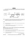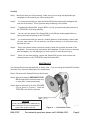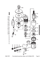
1
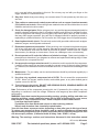
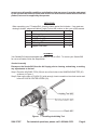
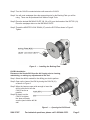
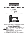
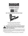
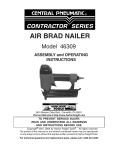
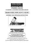
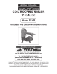
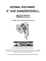
®
5” AIR SANDER/DRILL
Model 97187
ASSEMBLY AND OPERATING INSTRUCTIONS
3491 Mission Oaks Blvd., Camarillo, CA 93011
Visit our Web site at http//www.harborfreight.com
Copyright© 2004 by Harbor Freight Tools®. All rights reserved. No portion of this manual or any artwork contained therein may be reproduced in any shape or form without the
express written consent of Harbor Freight Tools.
For technical questions or replacement parts, please call 1-800-444-3353.
SPECIFICATIONS
Free Speed
Recommended Air Pressure
Air Consumption
Weight
Air Inlet Size
Chuck Type
18,000 RPM
90 PSI
4 CFM
2 lbs.
1
/4” NPT
3
/8” Keyless Chuck
save this manual
You will need the manual for the safety warnings and cautions, assembly instructions, operating
procedures, maintenance procedures, trouble shooting, parts list, and diagram. Keep your
invoice with this manual. Write the invoice number on the inside of the front cover. Keep both
this manual and your invoice in a safe, dry place for future reference.
Safety Warnings and Precautions
WARNING: When using tool, basic safety precautions should always be followed to reduce
the risk of personal injury and damage to equipment.
Read all instructions before using this tool!
1. Keep work area clean. Cluttered areas invite injuries.
2. Observe work area conditions. Do not use machines or power tools in damp or wet locations.
Don’t expose to rain. Keep work area well lighted. Do not use electrically powered tools in
the presence of flammable gases or liquids.
3. Keep children away. Children must never be allowed in the work area. Do not let them handle
machines, tools, or extension cords.
4. Store idle equipment. When not in use, tools must be stored in a dry location to inhibit rust.
Always lock up tools and keep out of reach of children.
5. Use the right tool for the job. Do not attempt to force a small tool or attachment to do the
work of a larger industrial tool. There are certain applications for which this tool was designed.
It will do the job better and more safely at the rate for which it was intended. Do not modify
this tool and do not use this tool for a purpose for which it was not intended.
6. Dress properly. Do not wear loose clothing or jewelry as they can be caught in moving parts.
Protective, electrically non-conductive clothes and non-skid footwear are recommended when
working. Wear restrictive hair covering to contain long hair.
7. Use eye protection. Always wear ANSI approved impact safety goggles. Wear a full face
shield if you are producing metal filings or wood chips. Wear an ANSI approved dust mask or
respirator when working around metal, wood, and chemical dusts and mists.
8. Do not overreach. Keep proper footing and balance at all times. Do not reach over or across
running machines.
9. Maintain tools with care. Keep tools clean for better and safer performance. Follow instructions
for changing accessories. Inspect tool periodically and if any part appears broken or damaged,
have it repaired by an authorized technician. The handles must be kept clean, dry, and free
from oil and grease at all times.
10. Disconnect power. Disconnect tool from air compressor when not in use and before changing
accessories, maintaining, repairing, or cleaning.
11. Remove adjusting keys and wrenches. Check that adjusting wrenches are removed from
the tool or machine work surface before connecting it to its power source.
12. Avoid unintentional starting. Be sure the air compressor switch is in the Off position when
SKU 97187
For technical questions, please call 1-800-444-3353.
Page 2
not in use and before connecting to this tool. Do not carry any tool with your finger on the
trigger, whether it is connected or not.
13. Stay alert. Watch what you are doing, use common sense. Do not operate any tool when you
are tired.
14. Take caution as some woods contain preservatives such as copper chromium arsenate
(CCA) which can be toxic. When cutting these materials extra care should be taken to avoid
inhalation and minimize skin contact.
15. Check for damaged parts. Before using any tool, any part that appears damaged should be
carefully checked to determine that it will operate properly and perform its intended function.
Check for alignment and binding of moving parts; any broken parts; and any other condition
that may affect proper operation. Any part that is damaged should be properly repaired or
replaced by a qualified technician. Do not use the tool if the trigger does not operate properly.
16. Guard against electric shock. Prevent body contact with grounded surfaces such as pipes,
radiators, ranges, and refrigerator enclosures.
17. Replacement parts and accessories. When servicing, use only identical replacement parts.
Use of any other parts will void the warranty. Only use accessories intended for use with this
tool. All accessories used must be rated 18,000 RPM or greater. Before each use, inspect
the accessory for damage or excess wear. Never use a damage or worn out accessory.
18. Do not operate tool if under the influence of alcohol or drugs. Read warning labels on
prescriptions to determine if your judgment or reflexes are impaired while taking drugs. If there
is any doubt, do not operate the tool.
19. Use proper size and type extension cord. If an extension cord is required for the compressor,
it must be of the proper size and type to supply the correct current to the tool without heating
up. Otherwise, the extension cord could melt and catch fire, or cause electrical damage to the
tool.
20. Maintenance. For your safety, service and maintenance should be performed regularly by a
qualified technician.
21. Use clean, dry, regulated, compressed air at 90 PSI. Do not exceed the recommended
90 PSI. Never use oxygen, carbon dioxide, combustible gases, or any other bottled gas as
a power source for this tool.
22. This tool has no safety shield. DO NOT USE GRINDING DISCS, GRINDING WHEELS OR
CUT-OFF WHEELS WITH THIS TOOL.
Note: Performance of the compressor powering this tool (if powered by line voltage) may vary
depending on variations in local line voltage. Extension cord usage may also affect compressor
performance.
WARNING: Some dust created by power sanding, sawing, grinding, drilling, and other construction activities, contain chemicals known [to the State of California] to cause cancer,
birth defects or other reproductive harm. Some examples of these chemicals are:
*Lead from lead-based paints
*Crystalline silica from bricks and cement or other masonry products
*Arsenic and chromium from chemically treated lumber
Your risk from these exposures varies, depending on how often you do this type of work.
To reduce your exposure to these chemicals: work in a well ventilated area, and work with
approved safety equipment, such as those dust masks that are specially designed to filter
out microscopic particles. (California Health & Safety Code 25249.5, et seq.)
Warning: The warnings, cautions, and instructions discussed in this instruction manual
REV 01/06; REV 03/06
SKU 97187
For technical questions, please call 1-800-444-3353.
Page 3
cannot cover all possible conditions and situations that may occur. It must be understood
by the operator that common sense and caution are factors which cannot be built into this
product, but must be supplied by the operator.
UNPACKING
When unpacking your 5” Sander/Drill, check the items against the list below. If any parts are
missing or broken, please call Harbor Freight Tools at the number on the cover of this manual.
Item#
N/A
26
30
29
28
27
Description
Drill Assembly
Holding Tool
5-1/2” Backing Plate
4-1/2” Backing Plate
3” Backing Plate
Adapter Lock Down
Qty
1
1
1
1
1
1
ASSEMBLY
Your Sander/Drill comes assembled and ready for use as a Drill. To convert your Sander/Drill
for use as a Sander, follow the Steps below.
Sander Assembly
Disconnect the Sander/Drill from the Air Supply prior to cleaning, maintaining, or making
any adjustments to the tool.
Step 1:Place the HOLDING TOOL (26) into one of two holes in the SANDING ADAPTER (25)
as shown in FIgure 1.
Step 2:Open up the jaws of CHUCK (31) wide enough, insert screwdriver into chuck center and
loose off CHUCK CENTER SCREW (32).
Figure 1 — Installing the Holding Tool
SKU 97187
For technical questions, please call 1-800-444-3353.
Page 4
Step 3:Turn the CHUCK counterclockwise until remove the CHUCK.
Step 4:You will need sandpaper discs the appropriate size for the Backing Plate you will be
using. These can be purchased from Harbor Freight Tools.
Step 5:Place the desired BACKING PLATE (28, 29 or 30) over the threads of the ROTOR (19).
Place the sandpaper disc over the BACKING PLATE.
Step 6:Thread the ADAPTER LOCK DOWN (27) onto the ROTOR as shown in Figure 2.
Tighten.
Figure 2 — Installing the Backing Plate
Drill Bit Installation
Disconnect the Sander/Drill from the Air Supply prior to cleaning,
maintaining, or making any adjustments to the tool.
Step 1:Select the drill bit needed for the drilling you wish to perform.
Step 2:Open up the Jaws of the Drill by turning the CHUCK (31)
as shown in Figure 3.
Step 3:When the Jaws are open wide enough to insert the
drill bit, slide the bit into the
CHUCK as far as
possible.
Step 4:By hand, turn the
CHUCK to tighten
the Jaws and make
sure the jaws hold the drill bit
well.
Figure 3 — Opening the Drill Chuck
SKU 97187
For technical questions, please call 1-800-444-3353.
Page 5
OPERATION
For best service, you should incorporate an oiler, regulator, and inline filter, as shown
in the diagram below. Hoses, couplers, oilers, regulators, and filters are all available at
Harbor Freight Tools.
Sander/
Drill
Figure 4 — Airline Oiler Assembly
Note: To connect this tool, we recommend a quick coupler/adapter (not included). Coupler/adapters are available at Harbor Freight Tools. For smoother operation, put
3-5 drops of pneumatic tool oil in the Hose Joint (6) before each use.
Setup
Step 1: Set the compressor’s pressure regulator to 90 PSI. Do not set the compressor’s outlet
regulator over 90 PSI.
Step 2:
Connect the Sander/Drill to the air compressor’s hose. If leaking is detected,
disconnect the air hose and repair before use.
Drilling
Note: This tool has no safety shield. DO NOT USE GRINDING DISCS, GRINDING WHEELS OR CUT-OFF WHEELS WITH THIS TOOL.
Note: All accessories used must be rated 18,000 RPM or greater.
Step 1:
Mark the material you wish to drill at the spot for the hole. Make sure your drill bit is
the correct size for the hole you need to make.
Step 2:
If possible, clamp the material in a vise to make sure the material does not move or
begin to spin while drilling.
REV 01/06; REV 03/06
SKU 97187
For technical questions, please call 1-800-444-3353.
Page 6
Step 3:
Wear eye protection to guard against flying wood or metal.
Step 4:
Set the compressor’s pressure regulator to 90 PSI. Do not set the compressor’s
outlet regulator over 90 PSI.
Step 5:
Connect the Sander/Drill to the air compressor’s hose. If leaking is detected,
disconnect the air hose and repair before use.
Step 6: Grip the Sander/Drill firmly. Place the drill bit on the spot marked in Step 1.
Step 7:
To begin drilling, press the TRIGGER (10) as shown in Figure 5.
CAUTION
Do not operate the Drill
before placing the drill bit
on the material.
Figure 5 — Drilling Operations
Step 8:
Your Sander/Drill has a variable speed for drilling. To vary the speed of the drilling
action, vary the pressure on the TRIGGER.
Step 9:
Drill only as deep as necessary. Do not drill into walls or other areas where you
cannot identify any possible hazards behind the drilling surface.
Step 10: When you have drilled the hole, remove the drill bit from the hole while the Sander/
Drill is still spinning. This is to prevent the drill getting caught in the hole and causing
damage.
SKU 97187
For technical questions, please call 1-800-444-3353.
Page 7
Sanding
Step 1: Identify the area you will be sanding. Make sure you are using the appropriate grit
sandpaper for the material you will be working with.
Step 2:
It is recommended that you start the Sander/Drill before placing the sandpaper disc
onto the work surface. This will reduce deep scratching in the surface.
Step 3:
To operate the Sander/Drill, grip the BODY (1) with your palm and place pressure on
the TRIGGER (10) to begin sanding.
Step 4:
You can vary the speed of the Sander/Drill to suit different sanding applications by
varying the pressure placed on the TRIGGER.
Step 5:
It is recommended that you sand in a random pattern to avoid sanding a side to side
into your work surface. Do not sand any one area too heavily, or for more than a few
seconds at a time.
Step 6:
Every few minutes during continuous sanding, check the condition and wear of the
sandpaper. If necessary, peel and replace the sandpaper. Do not use torn or severely
worn sandpaper, you may damage your work surface or suffer physical injury.
Step 7:
When you are done sanding, remove the Sander/Drill from the work surface and
release pressure on the TRIGGER to stop the Sander/Drill.
MAINTENANCE
Your Sander/Drill is best operated with an Airline Oiler. If you are using the Sander/Drill without
an Airline Oiler, follow the steps below for maintenance.
Step 1:Disconnect the Sander/Drill from the air hose.
Step 2:Apply a few drops of PNEUMATIC TOOL
OIL through the air line before each use,
or every hour if used continuously.
Step 3:Apply a few drops of oil to the TRIGGER
(10) as shown in Figure 6. Work the
TRIGGER a few times to lubricate.
CAUTION
Do not use detergent oil or additives as
these lubricants will cause accelerated
wear to the seals in the tool.
SKU 97187
Figure 6 — Lubrication Points
For technical questions, please call 1-800-444-3353.
Page 8
Parts list
Item# Description
1Body
2
Control Pin
3
Rubber Gasket
4Ball
5Spring
6
Hose Joint
7
Rubber Gasket
8O-Ring
9Regulator
10Trigger
11Pin
12Pin
13
Housing Lock Ring
14Bearing
15Spacer
16
Rear End Plate
QtyItem#Description
1
17Cylinder
1
18Vanes
1
19Rotor
1
20Bushing
1
21
Front End Plate
1
22Spacer
1
23Bearing
1
24
Cylinder Housing
1
25
Sanding Adapter
1
26
Holding Tool
1
27
Adapter Lock Down
1
28
Backing 3” Plate
1
29
Backing 4-1/2” Plate
1
30
Backing 5-1/2” Plate
1
31
Keyless Chuck
1
32
Chuck Center Screw
Qty
1
4
1
1
1
1
1
1
1
1
1
1
1
1
1
1
PLEASE READ THE FOLLOWING CAREFULLY
THE MANUFACTURER AND/OR DISTRIBUTOR HAS PROVIDED THE PARTS DIAGRAM IN THIS
MANUAL AS A REFERENCE TOOL ONLY. NEITHER THE MANUFACTURER NOR DISTRIBUTOR MAKES ANY
REPRESENTATION OR WARRANTY OF ANY KIND TO THE BUYER THAT HE OR SHE IS QUALIFIED TO MAKE ANY
REPAIRS TO THE PRODUCT OR THAT HE OR SHE IS QUALIFIED TO REPLACE ANY PARTS OF THE PRODUCT.
IN FACT, THE MANUFACTURER AND/OR DISTRIBUTOR EXPRESSLY STATES THE ALL REPAIRS AND PARTS
REPLACEMENTS SHOULD BE UNDERTAKEN BY CERTIFIED AND LICENSED TECHNICIANS AND NOT BY THE
BUYER. THE BUYER ASSUMES ALL RISK AND LIABILITY ARISING OUT OF HIS OR HER REPAIRS TO THE
ORIGINAL PRODUCT OR REPLACEMENT PARTS THERETO, OR ARISING OUT OF HIS OR HER INSTALLATION
OF REPLACEMENT PARTS THERETO.
90 Day Warranty
Harbor Freight Tools Co. makes every effort to assure that its products meet high quality and durability standards, and warrants to
the original purchaser that this product is free from defects in materials and workmanship for the period of 90 days from the date of
purchase. This warranty does not apply to damage due directly or indirectly, to misuse, abuse, negligence or accidents, repairs or alterations outside our facilities, criminal activity, improper installation, normal wear and tear, or to lack of maintenance. We shall in no
event be liable for death, injuries to persons or property, or for incidental, contingent, special or consequential damages arising from
the use of our product. Some states do not allow the exclusion or limitation of incidental or consequential damages, so the above
limitation of exclusion may not apply to you. This warranty is expressly in lieu of all other warranties, express
or implied, including the warranties of merchantability and fitness.
To take advantage of this warranty, the product or part must be returned to us with transportation charges prepaid. Proof of purchase
date and an explanation of the complaint must accompany the merchandise. If our inspection verifies the defect, we will either repair
or replace the product at our election or we may elect to refund the purchase price if we cannot readily and quickly provide you with
a replacement. We will return repaired products at our expense, but if we determine there is no defect, or that the defect resulted
from causes not within the scope of our warranty, then you must bear the cost of returning the product.
This warranty gives you specific legal rights and you may also have other rights which vary from state to state.
3491 Mission Oaks Blvd. • PO Box 6009 • Camarillo, CA 93011 • (800) 444-3353
SKU 97187
For technical questions, please call 1-800-444-3353.
Page 9
ASSEMBLY DIAGRAM
32
NOTE: Some parts are listed and shown for illustration purposes only, and are
not available individually as replacement parts.
Page 10
For technical questions, please call 1-800-444-3353.
SKU 97187