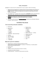
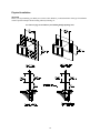
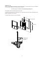
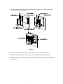
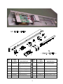
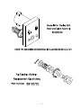
1
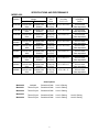
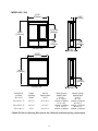
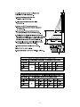
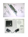
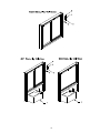
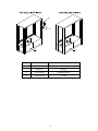
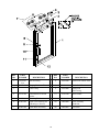
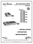
600 Series
Security Windows
Model 600
Model 601 / 603
Model 602 / 604
Drive-Thru Window
TABLE OF CONTENT
Topic
Page
Disclaimer
Serial Number Identification
Contact Sheet
Introduction
Product Information
Description
Specifications
Dimensions
Safety Information
Installation Procedures
Tools needed
Materials Needed
Physical Installation
Electrical Installation
Initial Operations and Testing
Adjustments and Calibrations
Operational Procedures
Modes of Operation
Operations
Control Identification, Explanation and Function
Maintenance
Maintenance Schedule
Daily
Monthly
Yearly
Service
Troubleshooting Guide (Cause and Effect)
Parts Lists
Parts List (Description/Part Number)
Drawings - Exploded Views / Schematics
Appendix “A” Adjusting or Re-hanging the Door
1
2
2
2
3
4
4
9
10
13
13
13
13
14
19
21
22
26
26
27
28
28
28
28
29
32
33
42
DISCLAIMER
READY ACCESS DISCLAIMS ANY LIABILITY FOR ANY DAMAGE OR HARM
CAUSED TO THE MODEL 600 DRIVE-THRU WINDOW, IT’S OPERATOR OR ANY
OTHER EQUIPMENT HOWEVER CAUSED IF THE MODEL 600 DRIVE-THRU
WINDOW IS REPAIRED OR SERVICED BY ANYONE OTHER THAN AN
AUTHORIZED SERVICE ENGINEER OR CONTRARY TO THE MANUFACTURERS
WRITTEN INSTRUCTION CONTAINED HEREIN.
THIS MANUAL IS INTENDED FOR USE BY THE IN-HOUSE OR AUTHORIZED FIELD
SERVICE ENGINEERS AND SALES REPRESENTATIVES
The manufacturer maintains the right to update, add or issue a new service manual at any time without
notice, thereby rendering all previous issues obsolete.
Please write the Serial Number and Installation Date for your drive-thru window in the spaces provided.
Serial Number
Date of Installation
CONTACT INFORMATION
FOR SALES AND SERVICE CONTACT
Ready Access
1815 Arthur Drive
West Chicago, Illinois 60185
Email: [email protected]
Tel: 630-876-7766
Tel: 800-621-5045
Fax: 630-876-7767
Website: www.ready-access.com
2
INTRODUCTION
The Ready Access window is quality designed to give you years of reliable, trouble-free service. Each
window is shipped pre-assembled, fully glazed and ready for installation. All Ready Access windows are
thoroughly tested prior to shipping.
The 600 Series of Single Door Slider Windows are the only completely modular security drive-thru system
designed to meet your specific security needs. With options including a selection of security glazing and
two different operating methods, this window is adaptable to your level of security needs.
The Model 600 drive-up window comes in two versions, manual and a fully automatic / electric model.
The electric version is fully automatic with a manual override in case of a power outage. The door will
open and close by stepping into an out of the light beam sensor.
This attractive and economical window is ideal for a drive-thru or walk up application. The large service
opening is suitable for both large and small operations. It is available in one standard width, 47 ½” and
three standard window heights, 30”H, 35 ¾" H and 43 ½” H.
The Model 601 drive-up window has a moveable service panel and comes in two versions, manual and a
fully automatic / electric model. The electric version is fully automatic with a manual override in case of a
power outage. The door will open and close by stepping into and out of the light beam sensor.
The Model 603 has a Stationary Panel. In high-risk areas the fixed glass allows for ample visibility
without the risk of face-to-face contact.
These attractive and economical windows are ideal for a drive-thru or walk up application. The large
service opening is suitable for both large and small operations. It is available in one standard size, 47 ½”
W x 58 ½” H x 4 ½” D, with additional heights available.
The Model 602 drive-up window has a moveable service panel and comes in two versions, manual and a
fully automatic / electric model. The electric version is fully automatic with a manual override in case of a
power outage. The door will open and close by stepping into and out of the light beam sensor.
The Model 604 has a Stationary Panel. In high-risk areas the fixed glass allows for ample visibility
without the risk of face-to-face contact.
These attractive and economical windows are ideal for a drive-thru or walk up application. The large
service opening is suitable for both large and small operations. It is available in one standard size, 47 ¾”
W x 58 ½” H x 17” D, with additional heights available.
An optional full sized stainless steel interior/exterior counter is available for most Ready Access windows.
When used with the READY ACCESS pass-thru air curtain system, the flush mounted single panel-sliding
window will provide the crew and customer with comfort during winter (AA300 Only) and a bug free
environment during the summer.
3
PRODUCT INFORMATION
Model 600
•
The Model 600 has a moveable Service Panel.
This offers the option of servicing customers personally. The service panel self latches each time
it closes and features a deadbolt lock for complete security during closed hours.
•
Manual or Electric Operations
The Model 600 Single Door Slider keeps building costs down by offering the window in a manual
operating style. Or for those who experience heavier traffic, an electric operating style is also
available. Electric models meet health department requirements for self-closing units.
•
Ease of Operation
In a manual operation, the inside attendant pulls the door handle, to open the door. With a fully
automated operation, the operator simply steps into the presence sensor and the movable
window panel will slide open. When the operator steps out of the presence sensor, the movable
window panel will automatically close. The range for the presence sensor is adjustable to specific
customer needs.
•
Quality Construction
Anodized aluminum extrusions, stainless steel and a selection of glass options combine to give
you an attractive secure window that not only enhances building exteriors, but will not rust, pit or
weather. Track free bottom sill provides for a contaminant free surface.
•
Finish
This unit is currently available in a clear or bronze anodized aluminum finish or can be powder
coat painted in a rainbow of color choices.
•
Fully Assembled, Ready to Install
Ready Access windows are shipped completely pre-assembled, and fully glazed for lower
installation costs. Normal installation takes less than two hours.
•
Warranty and Service Support
Your Ready Access window comes with a one year limited warranty on parts and labor provided
by a worldwide service organization.
STANDARD OPTIONS
•
3 standard window dimensions with 3 glass types are available: (See Chart on Page # 9)
•
A retrofit kit is available for the Model 600 Single Door Slider that easily upgrades the window
from a manual operation to a fully automatic operation.
•
An inside/outside stainless steel shelf is also available.
4
Model 601 / 603
•
The Model 601 has a moveable Service Panel.
This offers the option of servicing customers personally. The service panel self latches each time
it closes and features a deadbolt lock for complete security during closed hours.
•
The Model 603 has a Stationary Panel.
In high-risk areas the fixed glass allows for ample visibility without the risk of face-to-face
contact.
An optional full sized S.S. inside counter available.
•
Manual or Electric Operations.
The Model 601 Single Door Slider helps to keep building costs down by offering the window in a
manual operating style. Or for those who experience heavier traffic, an electric operating style is
also available. Electric models meet health department requirements for self-closing units.
•
Ease of Operation
In a manual operation, the inside attendant pulls the door handle, to open the door. With a fully
automated operation, the operator simply steps into the presence sensor and the movable
window panel will slide open. When the operator steps out of the presence sensor, the movable
window panel will automatically close. The range for the presence sensor is adjustable to specific
customer needs.
•
Security Transaction Drawer.
Security Transaction Drawer: The stainless steel transaction drawer allows for the secure
transfer of goods and currency without the risk of personal contact. A large 18- 5/16"W x 9-1/2"H
x 14-9/32" Deep transfer area is large enough for a case of soft drinks while the money clip and
change cup allow for the convenient handling of money. The drawer automatically locks when
closed and has a manual latch lock to prevent break-ins when the facility is closed. Features
level-3 bullet resistance protection
NOTE: This drawer is Optional for the Model 601 and Standard on the Model 603 Window.
o
Speaker System.
The pre-wired speaker system provides clear communication with customers without the need for
face-to-face contact.
NOTE: The speaker system is Optional for the Model 601 and Standard on the Model 603
Window.
•
Quality Construction
Anodized aluminum extrusions, stainless steel and a selection of glass options combine to give
you an attractive secure window that not only enhances building exteriors, but will not rust, pit or
weather.
•
Finish
This unit is currently available in a clear or bronze anodized aluminum finish or can be powder
coat painted in a rainbow of color choices.
5
•
Fully Assembled, Ready to Install
Ready Access windows are shipped completely pre-assembled, and fully glazed for lower
installation costs. Normal installation takes less than two hours.
•
Warranty and Service Support
Your Ready Access window comes with a one year limited warranty on parts and labor provided
by a worldwide service organization.
STANDARD OPTIONS.
•
3 standard window dimensions with 3 glass types are available: (See Chart on Page # 9)
•
An inside stainless steel shelf is also available.
GLASS OPTIONS.
Model 601
•
Impact Resistant Glazing: Offers protection against "smash & grab" theft and forced entry.
•
Level 1 Bullet Resistant Glazing: Offers protection against "smash & grab" theft, forced entry,
and gunshots. Glazing is recognized by Underwriters Laboratories as providing Level 1 (9mm)
handgun protection per UL Standard 752.
Model 603
•
Level 3 Bullet Resistant Glazing: Ideal for high-risk businesses and locations. Protects against
break-ins and attacks. Glazing is recognized by Underwriters Laboratories as providing Level 3
(.44 Magnum) handgun protection per UL Standard 752.
Note: Other glazing options available.
6
Model 602 / 604
•
The Model 602 has a moveable Service Panel.
This offers the option of servicing customers personally. The service panel self latches each time
it closes and features a deadbolt lock for complete security during closed hours.
•
The Model 604 has a Stationary Panel.
In high-risk areas the fixed glass allows for ample visibility without the risk of face-to-face
contact.
•
Manual or Electric Operations.
The Model 602 Single Door Slider helps to keep building costs down by offering the window in a
manual operating style. Or for those who experience heavier traffic, an electric operating style is
also available. Electric models meet health department requirements for self-closing units.
•
Ease of Operation
In a manual operation, the inside attendant pulls the door handle, to open the door. With a fully
automated operation, the operator simply steps into the presence sensor and the movable
window panel will slide open. When the operator steps out of the presence sensor, the movable
window panel will automatically close. The range for the presence sensor is adjustable to specific
customer needs.
•
Security Transaction Drawer.
Security Transaction Drawer: The stainless steel transaction drawer allows for the secure
transfer of goods and currency without the risk of personal contact. A large 18- 5/16"W x 9-1/2"H
x 14-9/32" Deep transfer area is large enough for a case of soft drinks while the money clip and
change cup allow for the convenient handling of money. The drawer automatically locks when
closed and has a manual latch lock to prevent break-ins when the facility is closed. Features
level-3 bullet resistance protection
NOTE: This drawer is Optional for the Model 602 and Standard on the Model 604 Window.
o
Speaker System.
The pre-wired speaker system provides clear communication with customers without the need for
face-to-face contact.
NOTE: The speaker system is Optional for the Model 602 and Standard on the Model 604
Window.
•
Quality Construction
Anodized aluminum extrusions, stainless steel and a selection of glass options combine to give
you an attractive secure window that not only enhances building exteriors, but will not rust, pit or
weather.
•
Finish
This unit is currently available in a clear or bronze anodized aluminum finish or can be powder
coat painted in a rainbow of color choices.
7
•
Fully Assembled, Ready to Install
Ready Access windows are shipped completely pre-assembled, and fully glazed for lower
installation costs. Normal installation takes less than two hours.
•
Warranty and Service Support
Your Ready Access window comes with a one year limited warranty on parts and labor provided
by a worldwide service organization.
STANDARD OPTIONS.
•
3 standard window dimensions with 3 glass types are available: (See Chart on Page # 9)
•
An inside stainless steel shelf is also available.
GLASS OPTIONS.
Model 602
•
Impact Resistant Glazing: Offers protection against "smash & grab" theft and forced entry.
•
Level 1 Bullet Resistant Glazing: Offers protection against "smash & grab" theft, forced entry,
and gunshots. Glazing is recognized by Underwriters Laboratories as providing Level 1 (9mm)
handgun protection per UL Standard 752.
Model 604
•
Level 3 Bullet Resistant Glazing: Ideal for high-risk businesses and locations. Protects against
break-ins and attacks. Glazing is recognized by Underwriters Laboratories as providing Level 3
(.44 Magnum) handgun protection per UL Standard 752.
Note: Other glazing options available.
8
SPECIFICATIONS AND PERFORMANCE
MODEL 600
Model
Number
USA
Unit
Voltage
International
Actual
Unit
Amps
Dimensions
In Inches
WXHxD
Weight
In Shipping
Carton
Model 600
110/120 VAC
60Hz
220/240 VAC
50/60Hz
15 A (US)
8 A (Int’l)
47½ x 43½ x 4½
150 to 450 lbs
Glass dependant
Model 600
110/120 VAC
60Hz
220/240 VAC
50/60Hz
15 A (US)
8 A (Int’l)
47½ x 35¾ x 4½
150 to 450 lbs
Glass dependant
Model 600
110/120 VAC
60Hz
220/240 VAC
50/60Hz
15 A (US)
8 A (Int’l)
47½ x 30 x 4½
150 to 450 lbs
Glass dependant
110/120 VAC
60Hz
220/240 VAC
50/60Hz
15 A (US)
8 A (Int’l)
47½ x 43½ x 4½
280 to 310 lbs
Glass dependant
601/603
110/120 VAC
60Hz
220/240 VAC
50/60Hz
15 A (US)
8 A (Int’l)
47½ x 35¾ x 4½
280 to 310 lbs
Glass dependant
601/603
110/120 VAC
60Hz
220/240 VAC
50/60Hz
15 A (US)
8 A (Int’l)
47½ x 30 x 4½
280 to 310 lbs
Glass dependant
602/604
110/120 VAC
60Hz
220/240 VAC
50/60Hz
15 A (US)
8 A (Int’l)
47½ x 43½ x 17
300 to 410 lbs
Glass dependant
602/604
110/120 VAC
60Hz
220/240 VAC
50/60Hz
15 A (US)
8 A (Int’l)
47½ x 35¾ x 17
300 to 410 lbs
Glass dependant
602/604
110/120 VAC
60Hz
220/240 VAC
50/60Hz
15 A (US)
8 A (Int’l)
47½ x 30 x 17
300 to 410 lbs
Glass dependant
601/603
Glass Options
Model 600
Insulated
Smash and Grab
Level 1 Glazing
Model 601
Thermo Payne
Smash and Grab
Level 1 Glazing
Model 602
Thermo Payne
Smash and Grab
Level 1 Glazing
Model 603
Thermo Payne
Smash and Grab
Level 1 Glazing
Level 3 Glazing
Model 604
Thermo Payne
Smash and Grab
Level 1 Glazing
Level 3 Glazing
9
Dimensions
Model 600
47.50"
[1207mm]
4.50"
[114mm]
43.50"
[1105mm]
34.75" SO
[883mm]
MODEL 600
Dimensions
In Inches
WxHxD
Service
Opening Size
WxH
Glazing Rough
Opening Size
WxH
47 ¾” x 43 ¾”
1213mm x 1111mm
Masonry Rough
Opening Size
WxH
48” x 44”
1219mm x 1118mm
47½ x 43½ x 4½
20” x 35”
47½ x 35¾ x 4½
20” x 27 ¼”
47 ¾” x 36”
1213mm x 914mm
20” x 21 ½”
47 ¾” x 30 ¼”
1213mm x 768mm
48” x 36 ¼”
1219mm x 921mm
48” x 30 ½”
1219mm x 775mm
47½ x 30 x 4½
10
MODEL 601 / 603
47.50"
[1207mm]
4.50"
[114mm]
34.75" SO
[883mm]
58.50"
[1486mm]
17.00"
[432mm]
MODEL 601
15.00"
[381mm]
2.00"
[51mm]
17.00"
[432mm]
47.56"
[1208mm]
4.50"
[114mm]
58.50"
[1486mm]
15.00"
[381mm]
MODEL 603
17.00"
[432mm]
Dimensions
In Inches
WxHxD
Height
Including
Drawer
Service
Opening Size
WxH
47½ x 43½ x 4½
58 ½” H
20” x 34 ¾”
47½ x 35¾ x 4½
50 ¾” H
20” x 27”
* 47½ x 30 x 4½
45” H
20” x 21 ½”
Glazing Rough
Opening Size
WxH
47 ¾” x 58 ¾”
1213mm x 1492mm
47 ¾” x 51”
1213mm x 1295mm
47 ¾” x 45 ¼”
1213mm x 1124mm
2.00"
[51mm]
Masonry Rough
Opening Size
WxH
48” x 59”
1219mm x 1499mm
48” x 51 ¼”
1219mm x 1302mm
48” x 45 ½”
1219mm x 1156mm
* Model 601 Service Opening Size passes the California restricted opening requirements.
11
MODEL 602 / 604
47.50"
[1206mm]
4.50"
[114mm]
34.75" SO
[883mm]
60.50"
[1537mm]
17.00"
[432mm]
MODEL 602
17.00"
[432mm]
17.00"
[432mm]
47.50"
[1207mm]
60.50"
[1537mm]
17.00"
[432mm]
17.00"
[432mm]
MODEL 604
Dimensions
In Inches
WxHxD
Height
Including
Drawer
Service
Opening Size
WxH
47½ x 43½ x 17
60 ½” H
20” x 34 ¾”
47½ x 35¾ x 17
52 ¾” H
20” x 27”
* 47½ x 30 x 17
47” H
20” x 21 ¼”
Glazing Rough
Opening Size
WxH
47 ¾” x 60 ¾”
1213mm x 1543mm
47 ¾” x 53”
1213mm x 1346mm
47 ¾” x 47 ¼”
1213mm x 1200mm
Masonry Rough
Opening Size
WxH
48” x 61”
1219mm x 1549mm
48” x 53 ¼”
1219mm x 1353mm
48” x 47 ½”
1219mm x 1206mm
* Model 602 Service Opening Size passes the California restricted opening requirements.
12
Safety Information
WARNING: To avoid the risk of fire, Electric Shock or injury to persons, observe the following:
1. Before servicing or cleaning the unit, switch the power off at the mechanical switch near the unit
(Installed by an Electrician) or the electrical entry service panel/circuit breaker. (Load Center)
• OSHA LOCK OUT – TAG OUT procedures are to be observed to prevent power from being
switched on accidentally.
2. Any Installation and / or Electrical work must be done by QUALIFIED persons in accordance with
all applicable codes / standards and manufacturers recommendations and specifications.
3. DO NOT insert fingers and / or foreign objects into the Drive-Thru Window.
DO NOT block or tamper with the unit in any manner while it is in operation.
4. This product must not be used in Potentially Dangerous locations such as Flammable, Explosive
Chemical – laden environment.
Installation Procedures
Tools required to perform the installation
•
•
•
•
Electric Drill
Metal Drill bits –
?” (3mm)
¼” (6mm)
½” (13mm)
1” (25mm)
•
•
•
Screwdrivers – Slotted and Phillips
Hacksaw
Jack / Utility Knife
•
•
•
Flat File – Coarse
Caulking gun
¼” Nut Driver
Extension Cord
Masonry drill bit –
¼” (6mm)
1” (25mm)
1½” (38mm)
•
•
Masonry Hole Saw – 1” (25mm)
Channel Lock Pliers
•
•
•
Tape Measurer
Wire Cutter
Step Ladder
•
Level
Materials required for installation
•
•
Window framing, architect specified and installed in building.
(Ready Access recommended material is ?“ (3mm) x 1 ¾” (44.5mm) x 4” (102mm) hollow
aluminum tubing or glazing channel)
Electrical Tape
•
•
Wire Nuts
Caulking – silicone (Color specific to the color of window)
•
•
Connectors for conduit as required
Shingle type shims – as required to level and plum the window
13
Physical Installation
Model 600
Before you begin installing your Ready Access Drive-Thru Window, you must determine what type of installation
will be required. Example: Wood Framing, Masonry Framing, etc.
See Chart on page 10 for Masonry and Glazing Rough Opening Sizes
14
MODEL 601 / 603
Before you begin installing your Ready Access Drive-Thru Window, you must determine what type of installation
will be required. Example: Wood Framing, Masonry Framing, etc.
See Chart on page 11 for Masonry and Glazing Rough Opening Sizes
The window must be installed square and plumb.
Installation illustrations are for reference only. Construction and local codes will determine
the proper installation of the window.
Contact Ready Access for more information.
"W" Rough Opening
"H" Rough Opening
604
Seri
es
602
Seri
es
Min distance from
the top of the sill
to the floor
36"
(914mm)
15
MODEL 602 / 604
Before you begin installing your Ready Access Drive-Thru Window, you must determine what type of installation
will be required. Example: Wood Framing, Masonry Framing, etc.
See Chart on page 12 for Masonry and Glazing Rough Opening Sizes
The window must be installed square and plumb.
Installation illustrations are for reference only. Construction and local codes will determine the
proper installation of the window.
Contact Ready Access for more information.
"W" Rough Opening
"H" Rough Opening
603
Seri
es
601
Seri
es
36"
(914mm)
16
Min distance from
the top of the sill
to the floor
WARNING:
TWO PEOPLE ARE REQUIRED FOR THE LIFTING AND
INSTALLATION OF THE WINDOW.
1. Confirm that the customer-supplied frame is made to accommodate the dimensions.
2. Confirm that AC power has been run and is ready for connection to the window.
3. Check shipping carton for any shipping damage and remove window from the carton.
4. Check window for any shipping damage.
NOTE: There are two wall-mounting applications. The mounting space can be
surrounded either by sidelights (windows) or masonry. In both cases the upper
part of the window above the counter top (window sill) fits flush with the outside
of the wall. The illustrations will show the walls with the sidelights, as this is the
most common application. (Figure 3 and 4)
Figure 3
Figure 4
NOTE: If mounting the window in a masonry wall the window mounts flush with the
outside finishing of the building. Drill points are scribed directly into the masonry.
The outside edge of the mullion should be flush with the outside finishing of the
building. (See Figure 3 and 4)
5. Position the window and place it into the customer-supplied frame. As shown in Figure 3 and 4
6. With one person holding the window in place, level the window using the shim shingles as
needed.
17
7. Using the window mounting holes as a template, drill a quantity of 4 – 3/16” (5mm) diameter
holes for mounting. (See Figure 5)
Figure 5
8. Take the window back out and drill the mounting holes. Set the anchors as needed.
9. With one person holding the window in place from the outside, set the mounting screws.
10. When the window is fully secured, seal the outside of the window to the frame or building using
silicone caulk.
18
Electrical Installation – 10/2003 Chassis Style
All power must be connected and wired by a qualified electrician and must be in compliance with all state and local
codes.
The incoming AC power line must be connected to the wires in the duplex box located in the top header (Per
Standard electrical code.) The green “grounding” wire is to be attached to the frame of the unit.
WARNING: Use only 110/120VAC – 60Hz source with a dedicated 15Amp circuit.
International power: 220/240VAC – 50/60Hz with a dedicated 8amp branch circuit.
WARNING: This must be a dedicated circuit. Other electrical equipment must not share the same line from the
15Amp circuit breaker.
WARNING: Turning off the front panel rocker switches does not remove the 110/120 volts of electrical power
form the unit
WARNING: To disconnect the power completely from this unit, turn OFF the mechanical switch near the unit
(Installed by an Electrician) or the electrical entry service panel/circuit breaker panel (Load Center) for this
unit.
• OSHA LOCK OUT – TAG OUT procedures are to be observed to prevent power from being switched on
accidentally.
1.
Remove the 2 screws holding on the AC access panel. Do not remove the slide channel cover.
19
2.
Wire the AC source line to the Terminal Block located in the header of the window.
AC Terminal Block
NOTE: THE GROUND WIRE (GREEN) IS ALWAYS IN THE CENTER OF THE
TERMINAL BLOCK. THE LINE (L1) IS INDICATED BY THE (RED) TAB AND THE
RETURN (NEUTRAL) IS INDICATED BY THE (WHITE) TAB.
3.
Turn “ON” the power to the unit. (Load center circuit breaker and power switch on the
“Control Panel”.
4.
Test window operations. See “Testing Procedures”.
20
Initial Window Operation
Testing Procedures
Action
Reaction
Turn the power “OFF” at the rocker switch
located on the controller unit.
Manually open and close the door several times.
When the door is opening, the “MOTOR RUN”
lamp will illuminate green. When the door is
closing, “MOTOR RUN” lamp will illuminate red.
The “POWER” lamp must illuminate during both
operations. If neither of these lamps illuminate
during any of the processes, proceed to the
“Troubleshooting” section.
Turn the power “ON” at the rocker switch located
on the controller unit.
Break the electric eye beam to open the door.
The door will open.
With the power “ON” break the electric eye beam
momentarily to open and close the door.
The door will open. They will remain in the open
position for either approximately 3.0 or 6.0
seconds before closing (Default Settings)
With the power “ON” press the “CLOSE DELAY”
button located on the controller unit once and
break the electric eye beam to open the door
The door will open and the length of time that the
door remains open will toggle between 3.0 and
6.0 seconds before closing. (Default Settings)
With the power “ON” break the electric eye beam
momentarily to open and close the door. Insert an
object at least 4” (101.6mm) wide between the
door and the frame as the door closes.
The door will automatically reverse their action
(the door will open), when an object is caught
between or restricting the closing of the door.
21
Adjustments and Calibrations
SuperScan Presence Sensor Adjustment Instruction
Once the window is installed and the power is hooked up to the drive-thru window unit, you will need to
test and set the range of the presence sensor. This is done to determine the best compatibility for your
service applications. The presence sensor can be adjusted in many ways to work with different
applications.
The tools required to perform this test and adjustments are: Phillips Head Screwdriver, Straight Blade
Screwdriver and a ¼” Nut Driver.
If the drive-thru window stays open after the power is turned on and the beam break light is “ON”, the
sensor is detecting the floor or the counter top.
To adjust the presence sensor to the floor:
1. Turn the power “OFF” to the drive-thru window.
2. Remove one of the plastic end caps from the sensor body. (Preferably the left side)
3. Remove the black plastic lens cover.
Next to the “Right Eye” you will see an adjustment dial. This dial is used for adjusting the sensor to the
distance from the floor. The dial is in a clock format. The maximum distance is achieved at the 9 o’clock
position after the right eye clicks back into it’s broadest setting. The minimum distance is achieved at the
9 o’clock position before the right eye clicks back into it’s broadest setting.
NOTE: TURN THE DIAL IN A COUNTER_CLOCK_WISE FASHION ONLY.
If the Drive-Thru window stays open while standing far away from the wall or the window closes on you while
you are passing product out to the customer, Then the angle of the sensor needs to be adjusted.
Below are diagrams illustrating the different setting that can be done to adjust the distance from the wall.
22
23
Door Alignment
Adjustments to the door height and alignment are accomplished by turning one or both of the eccentric
nuts located at the top of the doorframe where it mounts to the slide track. (Figure 7)
Figure 7
Adjusting Nuts
24
Calibration:
The only calibration available on the new style DC-3 PC board is setting the close delay timer using the
dip switch package mounted near the ribbon cable connector.
The CLOSE DELAY TIMER is default set at 3 seconds
Follow the Chart Below for Changing
The Close Delay Time Settings
Dip Switch Settings
Time in
Switch Position
Seconds
1
2
3
4
ON
1
OFF
OFF
OFF
ON
2
OFF
OFF
OFF
ON
3
OFF OFF
OFF
ON
4
OFF OFF
OFF
5
OFF OFF
OFF
OFF
ON
ON
12
OFF
OFF
ON
ON
13
OFF
OFF
ON
ON
14
OFF
OFF
ON
15
OFF
OFF
OFF
ON
ON
23
OFF
OFF
ON
ON
24
OFF
OFF
ON
25
OFF
OFF
OFF
ON
ON
34
OFF OFF
ON
35
OFF OFF
OFF
ON
45
OFF OFF
OFF
The DC-2 PCB has two potentiometers
5
OFF
OFF
OFF
OFF
ON
OFF
OFF
OFF
ON
OFF
OFF
ON
OFF
ON
ON
The Window Select Dial is used to set the type of door
configuration for the model of window.
The Current Dial is used to increase or decrease the
power to the motor. This is adjusted to insure proper
operation.
25
Operation Procedures
Modes of Operation:
The Model 600 Single Door Slider window has two modes of operation, Manual and Automatic.
After installation of the Model 600 Manual or Electric Sliding window, completion of the testing procedures
and the installation of the decorative covers, the window is ready for normal use.
The Manual Mode: The opening and closing of the window is done by hand.
(DO NOT OPEN OR CLOSE THE DOOR WITH ANY UNDUE FORCE)
Manual Operations:
1. Unlock the deadbolt on the door.
2. Release the manual latch and push the door open.
3. Push the door closed and allow the manual latch reset.
4. Relock the deadbolt.
The Automatic Mode is reached by turning “ON” the main power to the window. Stepping in and out of
the sensor’s range opens and closes the door.
Automatic Operations:
1. On the controller unit, turn the power rocker switch to the “ON” position.
2. Check that the red portion of the rocker switch is visible and that the red power lamp is
illuminated
3. Break the electronic eye beam or step into the sensor beam path. The red beam break and green
motor run lamps go on.
4. Step out of the beam path and wait 3 to 6 seconds for the door to close. The red motor run lamp
and red close detect lamps will illuminate. After the door close note that the red power lamp and
the current detect lamps are “ON”.
5. If the door does not operate correctly, go to the troubleshooting guide in this manual. If the door
still do not operate properly, then call Ready Access at
1-800-621-5045
6. The door can be operated manually by pulling the manual release located at the top of the door.
NOTE: Turn the power off to the window to prevent any damage to the PCB.
Each operator must read the operations manual before operating the unit.
26
Controls Identification, Explanation and Function
Controller Unit
Lamps and
Switches
Power Lamp
Motor Run
Lamp
Function
This lamp indicates that the power rocker switch is on and the controller is receiving power.
The “MOTOR RUN” lamp indicates that power is being applied to the motor. When the door is
opening, lamp will illuminate green. When the door is closing, the lamp will illuminate red.
The lamp also allows for the diagnostic checking of the motor and motor wiring. To test, turn the
power “OFF” at the rocker switch and manually open and close the door. This will cause the lamp
to illuminate either green or red. The “POWER” lamp must illuminate during both operations. If
neither of these lamps illuminate during any of the processes, proceed to the “Troubleshooting”
section.
Beam Break
Lamp
This lamp indicates that the electric eye beam or presence sensor beam has been broken and/or the
“CLOSE DELAY” timer is still timing out.
Close Detect
Lamp
This lamp is red and indicates that a “CLOSE” sequence has been initiated. It will always light
during a door closure and will go out just before the door contacts the frame. When the lamp is out,
the automatic reverse feature is disabled.
Current
Detect Lamp
This lamp is red and indicates an overload has been detected. This lamp may light on opening but
is automatically disabled. The lamp will come on when the door is fully closed or when an
obstruction has been encountered
Beam Test
Switch
Pressing the “BEAM TEST” button once will test the operations of the door without using the
electric eye or presence sensor. To test, the operator should not be in the path of the light beam or
presence sensor.
Standing in the light beam while pressing the button will put the window into a test mode. This will
make the window continuously operate (open and close) automatically. You must turn the power
off and back on to reset the window.
Close Delay
Switch
Pressing this button will toggle the length of time that the door remains open between 1.5 and 3.0
seconds before closing.
27
Maintenance
Maintenance Schedule
Scheduled maintenance should be performed on a regular basis. This is to assure proper operation and
performance of the Model 600 windows.
Daily
Check the sill and drawer for foreign materials and/or syrup. (Anything that might cause the window to
bind up and not operate smoothly.)
Use warm soapy water or carbonated water to clean the window.
Monthly
Follow safety procedures before opening the unit.
Check the interior of the unit for any build up of any foreign materials using a dry cloth.
NOTE: KEEP ANY LIQUIDS OFF THE INTERIOR COMPONENTS.
Clean moving parts and lubricate with silicone or Teflon spray.
NOTE: Do NOT use Grease or Oils. Do NOT lubricate the motor clutch assembly.
Yearly
Have a service technician come in and perform a maintenance check on the unit.
28
SERVICE
Troubleshooting Guide
Issue
Power switch in the
“ON” position but the
light is not illuminated.
“BEAM BREAK” lamp is
“OFF” and does not
illuminate when the
electric eye is broken.
The door will not “AUTO
REVERSE” for an
obstruction when
closing and the motor
continue to run.
Probable Cause
Resolution
•
No power to the controller unit
Ø Main Circuit breaker is
defective or not “ON”
Ø The fuse on the power
supply is blown
Ø Main power rocker switch is
defective
Ø AC wiring is defective
•
Red Lamp/s not illuminating
•
Replace the PCB assembly cover
•
The 4 pin power connector to
the main PCB assembly is not
secure
•
Secure the connector/s to the power
supply
•
The connector/s to the rocker
switch are not secure
•
Secure the connector/s to the rocker
switch
•
Defective electric eye assembly
Ø Pressing the “BEAM TEST”
button on the controller unit
can test this. The door
should open, pause and
close. If the door operate
normally, check other
causes listed below
•
Replace the electric eye assembly
•
Loose electric eye cable from
the PCB
•
Secure the cable connector (3 or 4 pin)
•
Loose or broken wire/s in the
electric eye cable
•
Check that the electric eye cables are
secure and not broken
•
Defective lamp
•
Replace the PCB assembly cover
•
Defective PCB assembly
•
Replace the PCB assembly
•
Loose or broken wires to the
limit switches or the PCB
assembly
•
Secure or replace the cable assembly
•
Defective controller unit
•
Replace the controller unit
The “CURRENT
DETECT” lamp will not
illuminate.
29
Ø Reset or replace the main circuit
breaker in the load center
Ø Replace the fuse on the power
supply
Ø Test rocker switch with an
ohmmeter. Replace if necessary
Ø Check AC wiring for opens. Replace
if necessary
Issue
When the beam is
broken, the door does
not open. The red
“POWER” and “BEAM
BREAK” lights and the
green “MOTOR RUN”
light on the
CONTROLLER unit are
“ON”.
Probable Cause
Resolution
•
Defective motor assembly
Ø To test for a defective motor,
open and close the door with
the power “OFF”.
If the motor is faulty, the
red/green “MOTOR RUN”
lamp will not illuminate
•
Replace the motor assembly
•
Solenoid latch in the door is stuck
or defective
Ø To test for a defective
solenoid, manually open the
door halfway and break the
beam. The solenoid should
retract the hook and the door
should open, pause and close.
Break the beam again to verify
that the door are not opening
•
Replace the solenoid
Ø Check the wiring to the
solenoid
Beam Break Lamp is
“ON” and the door open,
but they do not close.
The door closes fully but
open back up as soon as
the door comes in
contact with the frame.
•
Defective components on the
cable drive assembly. (“S” hook,
cable, spring, chain, bearing
•
Replace the defective component
•
Loose or broken wires
•
Secure or Replace the cable assembly
•
Defective electric eye assembly
Ø Disconnect the cable for the
electric eye and press the
“BEAM TEST” button. If the
door operate properly the eye
is defective
•
Replace the eye assembly
•
Defective PCB assembly
Ø Disconnect the cable for the
electric eye and press the
“BEAM TEST” button. If the
door do not operate properly
the PCB is defective
•
Replace the PCB assembly
•
Loose or broken wires to the limit
switches or the PCB assembly
•
Secure or replace the cable assembly
•
Limit switch striker is loose or out
of alignment
•
Tighten and/or align the striker plate
•
Defective controller unit
•
Replace the controller unit
•
Loose Cable and Chain
•
Tighten the cable pulley
30
Issue
The “CLOSE DELAY”
switch is not working
properly.
Motor continues to run
after the door is fully
opened.
The door does not fully
close and goes into
AUTOREVERSE to the
fully open position.
Door may be sluggish in
operations.
The “CURRENT
DETECT” lamp will be
illuminated before the
“CLOSE DETECT”
lamp goes out.
(BEFORE REPLACING
THE MOTOR CALL
READY ACCESS FOR
FURTHER
INSTRUCTIONS)
The “BEAM TEST”
switch is not working
properly.
The “BEAM BREAK”
lamp is not illuminated
and the door do not
open.
Probable Cause
Resolution
•
Loose or broken connection to the
PCB Assembly
•
Secure the cable connector to the PCB
assembly or replace the control PCB
cover
•
Defective “CLOSE DELAY” switch
•
Replace the control PCB cover
•
Loose or broken wires to the limit
switches or the PCB assembly
•
Secure or replace the cable assembly
•
Defective “Open” limit switch
•
Replace the appropriate switch
•
Defective controller unit
•
Replace the controller unit
•
Spilled soft drink syrup residue is
under the door and on the weather
stripping of guide block
•
Clean the weather stripping, counter
and door guides on the bottom of the
door with soda water
•
Door are dragging on the counter
top
•
Adjust the door height and alignment.
(Refer to the adjustments section of
this manual)
•
Defective motor assembly
Ø To test for a defective motor,
open and close the door with
the power “OFF”. If the motor
is faulty, the red/green
“MOTOR RUN” lamp will not
illuminate
•
Replace the defective motor assembly
•
Defective CONTROLLER unit
•
Replace the CONTROLLER unit
•
Loose Cable and Chain
•
Tighten the cable pulley
•
Loose or broken connection to the
PCB assembly
•
Secure or replace the cable assembly
•
Defective CONTROLLER unit
•
Replace the CONTROLLER unit
•
Defective PCB assembly
•
Replace the PCB assembly
31
Parts Lists
Parts List (Description/Part Number)
Description
Cable & Chain Assy ( New Chassis )
Cable, BEA Sensor to PCB
(New Chassis)
Door Assembly
Current Part Previous Part
Number
Number
85001800
N/A
20112104
Note
N/A
Door Guide Kit
Call Manufacturer form part #, price and availability
85003400
N/S
Electric Chassis L/R - New Style 2003
85002120
N/A
Electric Chassis R/L - New Style 2003
85002110
N/A
Electric Eye/Reflector Kit -waist level
85000200
N/A
Eye Switch Retrofit
84000300
N/A
Handle - Manual Release - 600 L/R
Handle - Manual Release - 600 R/L
Hanging Hardware Kit (Adj. Nut) (2)
85002420
85002410
85183400
N/A
N/A
65183401
Latch Spring
00650269
N/A
Lock - Dead Lock
CALL FOR # N/A
Lock - Face Plate
CALL FOR # N/A
Lock - Mortise Thumb-Turn
CALL FOR # N/A
Lock - Pad
CALL FOR # N/A
Lock - Self Latch
85004400
N/A
Lock - Thumb-Turn 21-19-130
85004600
N/A
PC Board - DC3 as of 12/14/01
85002001
N/A
Power Supply (chassis only )
85001400
N/A
Power Supply Int'l (chassis only )
85001700
N/A
Retro Fit Kit - Model 600 R/L CLR MANL- 84001312
ELEC
Roller Block Replacement Kit - 2 Pcs
85003200
N/A
Roller Grove Bearing - KIT
Screw for inside cover, sensor striker
85003600
10010114
20010030
N/A
Sensor Assy - BEA - Model 600
85000800
N/A
Silicone Caulk - 8 oz - Aluminum
80050029
N/A
Silicone Caulk - 8 oz - Bronze
80050020
N/A
Solenoid & Hook Assy for Electric
Chassis L/R
Solenoid & Hook Assy for Electric
Chassis R/L
Switch - LIMIT FOR CHASSIS
85002920
N/A
New Style 2003 (chassis)
85002910
N/A
New Style 2003 (chassis)
85002200
N/A
Switch - Micro
20110281
N/A
Wired Switch Cover - Champagne
65184703
N/A
Not MOER or 275 after 2/99
New Style 2003 (chassis)
New Style 2003 (chassis)
N/A
32
SINGLE ROLLER
Drawings
Exploded Views
Page
Part Number
If Applicable
Description
28
N/A
29
85186700
Motor and Clutch Assembly (w/ Bracket Detached)
30
85152700
Clutch Assembly – Exploded View
31
65103500
Roller Block Assembly
31
85004300 / 4400
32
*****
Lock Dead Bolt
32
N/A
Window Frame – Exploded View (600, 601, 602, 603, 604)
33
N/A
Door Assembly – Exploded View
N/A
Electrical Schematic
Header Assembly – Exploded View
Lock Latch Assembly (Thumb Turn)
Schematics
34
33
REF
ID #
PART
NUMBER
REF
ID #
PART
NUMBER
5
20220003
DESCRIPTION
AC Terminal Block
1
85002910
1
85002920
6
20110281
Micro switch
2
85001400
7
20200142
Kilrol Pulley
*2
85001700
8
85001800
Cable and Chain Assy
85002002
220V Power Supply
(Int'l)
Control PCB Assy
3
9
85002120
Electric Chassis – L/R
4
85186700
Motor & Clutch Assy
9
85002110
Electric Chassis – R/L
DESCRIPTION
Solenoid and Hook Assy
R/L
Solenoid and Hook Assy
L/R
120V Power Supply
34
35
85003200
Roller Block Assembly
20220001
Mounting Block
85003600
Roller Grove Bearing
85004500
Thumb Turn
Lock Latch
85004400
Self-Closing
85004300
Electric
36
20090086
Dead Bolt Lock
20090084
Mortise
Thumb Turn
20090087
Face Plate
20110021
Speaker
Intercom
20110020
Phone
20110022
Power Supply
37
38
REF ID #
PART NUMBER
DESCRIPTION
1
Call for Part #
Drawer
2
40010030
Bumper
3
Call for Part #
Adjustment Screw
4
Call for Part #
Lock Nut
39
REF
ID #
PART
NUMBER
1
See Parts
List
85183400
2
3
REF
ID #
PART
NUMBER
8
85004500
DESCRIPTION
Latch Lock Thumb Turn
Hanging Hardware Kit
9
20091180
Latch Lock Electric
Cable Clamp
9
85004400
Chain and Micro Switch
Bracket
Mounting Block
10
65103300
Latch Lock
Self Closing
Door Handle
11
20090084
Lock – Mortise
Lock Assembly
Dead Bolt
Face Plate
DESCRIPTION
Door Assembly
4
66122300
5
20220001
6
85003600
Roller Grove Bearing Kit
(1 Bearing w/ Screws)
12a
20090086
7
85003200
Roller Block Assembly
12b
20090087
40
41
Appendix A
Adjusting or Re-hanging the Door
The distance of the door(s) above the mullion or counter top is adjusted by turning the eccentric nuts
located in the corners at the top of each door. The exploded view of the assembly is shown in Figure
1 below.
When a door has dropped, such that it impedes the movement of the door, it is necessary to re-adjust
the door to a given distance above the counter top. This is accomplished by loosening the two
Locking / Eccentric Nut combinations at the top of each door. Loosening the small locking nuts
allows the door to drop down and rest on the counter top.
Slide the door inward to the closed position and lock using the night lock. Insert two shims about
0.100” in thickness under each door. One at each end of the door is suggested. A standard coffee stir
or a tongue depressor is a bout 0.100” thick. This allows the door to set at a preset distance off the
counter top.
Starting with one of the Locking / Eccentric Nut combinations turn the eccentric nut until you feel
resistance and/or notice that the door is beginning to rise. Keeping the eccentric nut in that position,
tighten the locking nut down to approximately 30 lbs/in2 of torque.
Repeat the above step for each of the remaining Locking / Eccentric Nut combinations. Remove the
shims. The door should now be at the proper height as well as being square with each other.
42
Ready Access, 1815 Arthur Drive, West Chicago, Illinois 60185, Tel: 630-876-7766, Tel: 800-621-5045
Fax: 630-876-7767, Email: [email protected], Website: www.ready-access.com
43
3/06 600 SM 3-06