1
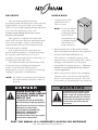
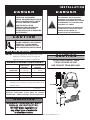
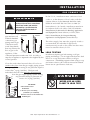
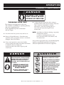
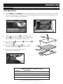
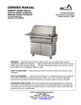
®
GAS F RY E R
F r y Te c h S e r i e s
ASF-60G shown with
optional automatic
basket lifts
AS F-60G and
AS F-75G
Gas Fryers
with
Basic Control
• I N STALLATION
ASF-75G shown with
optional automatic
basket lifts
• OPERATION
• MAI NTENANCE
W164 N9221 Water Street • P.O. Box 450 • Menomonee Falls, Wisconsin 53052-0450 USA
PHONE: 262.251.3800 • 800.558.8744 USA / CANADA
FAX: 262.251.7067 • 800.329.8744 U . S . A .
www.alto-shaam.com
PRINTED IN U.S.A.
ONLY
MN-28641 • 03/09
®
DELIVERY
U N PA C K I N G
This Alto-Shaam appliance has been
thoroughly tested and inspected to insure only the
highest quality unit is provided. Upon receipt,
check for any possible shipping damage and report
it at once to the delivering carrier. See
Transportation Damage and Claims section
located in this manual.
This appliance, complete with unattached
items and accessories, may have been delivered in
one or more packages. Check to ensure that all
standard items and options have been received
with each model as ordered.
Save all the information and instructions
packed with the appliance. Complete and return
the warranty card to the factory as soon as
possible to assure prompt service in the event of a
warranty parts and labor claim.
This manual must be read and understood by
all people using or installing the equipment
model. Contact the Alto-Shaam service
department if you have any questions concerning
installation, operation, or maintenance.
NOTE: All claims for warranty must include the
full model number and serial number of
the unit.
DANGER
BEFORE STARTING THE
APPLIANCE, MAKE CERTAIN
YOU DO NOT DETECT THE
ODOR OF GAS.
IF THE ODOR OF GAS IS DETECTED:
• DO NOT attempt to light any appliance.
• DO NOT touch any electrical switches.
• Extinguish any open flame.
• Use a telephone OUTSIDE THE
PROPERTY & IMMEDIATELY
contact your gas supplier.
• If unable to contact your gas supplier,
contact the fire department.
1. Carefully remove the
appliance from the
carton or crate.
NOTE: Do not discard the
carton and other
packaging material
until you have
inspected the unit
for hidden damage
and tested it for
proper operation.
®
®
2. Read all instructions in this manual carefully
before initiating the installation of this appliance.
DO NOT DISCARD THIS MANUAL.
This manual is considered to be part of the
appliance and is to be provided to the owner or
manager of the business or to the person
responsible for training operators. Additional
manuals are available from the Alto-Shaam
service department.
3. Remove all protective plastic film, packaging
materials, and accessories from the appliance
before connecting electrical power. Store any
accessories in a convenient place for future use.
WA R N I N G
In the event of loss of power to the
appliance, turn the “burner control
knobs” to the OFF position. Remove
food product from the unit. If burner
control fails to extinguish the flame,
shut off main gas valve located in
rear of unit.
KEEP THIS MANUAL IN A CONVENIENT LOCATION FOR REFERENCE.
Gas Fryer Operation & Care Manual • 1
I N S TA L L AT I O N
SAFETY PROCEDURES
AND PRECAUTIONS
Knowledge of proper procedures is essential to the
safe operation of electrically and/or gas energized
equipment. In accordance with generally accepted
product safety labeling guidelines for potential
hazards, the following signal words and symbols
may be used throughout this manual.
DANGER
Used to indicate the presence of a
hazard that WILL cause severe
personal injury, death, or substantial
property damage if the warning
included with this symbol is ignored.
WA R N I N G
Used to indicate the presence of a
hazard that CAN cause personal injury,
possible death, or major property
damage if the warning included with
this symbol is ignored.
1. This appliance is intended to cook, hold or
process foods for the purpose of human
consumption. No other use for this appliance is
authorized or recommended.
2. This appliance is intended for use in commercial
establishments where all operators are familiar
with the purpose, limitations, and associated
hazards of this appliance. Operating
instructions and warnings must be read and
understood by all operators and users.
3. Any troubleshooting guides, component views,
and parts lists included in this manual are for
general reference only and are intended for use
by qualified technical personnel.
4. This manual should be considered a permanent
part of this appliance. This manual and all
supplied instructions, diagrams, schematics,
parts lists, notices, and labels must remain with
the appliance if the item is sold or moved to
another location.
CAUTION
Used to indicate the presence of a
hazard that can or will cause minor or
moderate personal injury or property
damage if the warning included with
this symbol is ignored.
CAUTION
Used to indicate the presence of a hazard that can
or will cause minor personal injury, property
damage, or a potential unsafe practice if the
warning included with this symbol is ignored.
NOTE
For equipment delivered for use
in any location regulated by the
following directive:
DO NOT DISPOSE OF ELECTRICAL
OR ELECTRONIC EQUIPMENT WITH
OTHER MUNICIPAL WASTE.
N O T E : Used to notify personnel of
installation, operation, or
maintenance information that is
important but not hazard related.
Gas Fryer Operation & Care Manual • 2
I N S TA L L AT I O N
A S F - 7 5 G S P E C I F I C AT I O N S
DIMENSIONS
EXTERIOR
H x W x D:
STANDARD ACCESSORIES
■ Basket, Half-Size (2 INCLUDED AS STANDARD )
Brush Set ( ONE 3- BRUSH SET INCLUDED AS STANDARD )
■ ANGLE BRUSH
■ SCRUB BRUSH
■ STRAIGHT BRUSH
Filter, Paper (7 PAPER FILTERS INCLUDED AS STANDARD)
■ 7 COUNT REFILL PACKAGE
■ 100 COUNT REFILL PACKAGE
OPTIONS
■ Basket, Full-Size (48 CHICKEN PIECE CAPACITY )
■ Charcoal/Carbon ( 30 COUNT PKG. )
FILTERS
■ Reusable Mesh ( SINGLE FILTER)
■ Fry Pot Cover
■ Mobile Drawer Cover
■ Strainer/Skimmer
■ Oil Discard Hose
45-5/16" x 24-13/16" x 37-7/8"
(1150mm x 630mm x 961mm)
BASKET DIMENSIONS ( H X W X D)
11-1/2" x 12-3/4" x 21-3/4"
(292mm x 324mm x 552mm)
C A PA C I T Y
SHORTENING/OIL:
73 lb (33 kg)
LOAD CAPACITY:
13 lb (6 kg)
WEIGHT
MAXIMUM
MAXIMUM
EST.
360 lb
(163 kg)
520 lb
(236 kg)
DIMENSIONS: H x W x D
57" x 34" x 47"
(1448mm x 864mm x 1194mm)
NET WEIGHT:
SHIP WEIGHT:
CARTON
ASF-75G WITH LIFTS AND FILTRATION
BS-27140
BH-28692
BH-28693
BH-28691
FI-27791
FI-27794
BS-26998
FI-27648
FI-27014
5005136
5006073
CE-27400
HO-27686
ASF-75G, NO LIFTS OR FILTRATION
60-1/16" (1525mm)
°
3-1/2"
(89mm)
0°
15
ns
pe
Gas
Connection
1/2" NPT
Electrical
44-13/16" (1137mm)
51-5/16" (1302mm) LIFT UP
45-5/16" (1150mm) LIFT DOWN
24-13/16" (630mm)
31-9/16" (802mm)
12-7/16" (315mm)
31-13/16" (808mm)
Electrical
9"
(229mm)
Gas
Connection
1/2" NPT
61-5/8" (1564mm)
12
0
Do
or
o
Do
or
op
en
s
OIL
TROLLEY
37-7/8" (961mm)
60-1/16" (1525mm)
12-7/16"
(315mm)
24-13/16" (629mm)
Gas Fryer Operation & Care Manual • 3
2-7/8"
(72mm)
37-7/16" (950mm)
I N S TA L L AT I O N
A S F - 6 0 G S P E C I F I C AT I O N S
DIMENSIONS
EXTERIOR
H x W x D:
STANDARD ACCESSORIES
■ Basket, Half-Size (2
45-1/8" x 15-3/4" x 33-5/8"
Brush Set ( ONE 3- BRUSH
■ ANGLE BRUSH
■ SCRUB BRUSH
■ STRAIGHT BRUSH
(1146mm x 400mm x 854mm)
BASKET DIMENSIONS
(H
X W X D)
5-7/8" x 5-3/16" x 13-13/16"
(149mm x 131mm x 351mm)
SET INCLUDED AS STANDARD )
OPTIONS
■ Fry Pot Cover
NET WEIGHT:
WEIGHT
SHIP WEIGHT:
EST
33-5/8" (854mm)
31-1/2" (802mm)
Electrical Connection
2-7/8"
(72mm)
15
0°
6-5/8"
(168mm)
5-7/16"
(142mm) Gas Connection
Gas Fryer Operation & Care Manual • 4
44-3/8" (1127mm)
50-3/8" (1280mm) lift up
15-3/4"
(400mm)
23-3/8"
(592mm)
47-1/2" (1206mm)
CARTON
BH-28692
BH-28693
BH-28691
CE-27400
MAXIMUM
248 lb (113 kg)
330 lb (150 kg) EST
39" x 22" x 55" EST
DIMENSIONS :
(991mm x 559mm x 1397mm)
BS-27963
5007596
■ Strainer/Skimmer
CAPACITY
SHORTENING/OIL: 62 lb (28 kg)
INCLUDED AS STANDARD )
I N S TA L L AT I O N
DANGER
DANGER
IMPROPER INSTALLATION,
ALTERATION, ADJUSTMENT,
SERVICE, OR MAINTENANCE COULD
RESULT IN SEVERE INJURY, DEATH
OR CAUSE PROPERTY DAMAGE.
READ THE INSTALLATION,
OPERATING AND MAINTENANCE
INSTRUCTIONS THOROUGHLY
BEFORE INSTALLING OR SERVICING
THIS EQUIPMENT.
AVERTISSEMENT : UNE INSTALLATION,
UN AJUSTEMENT, UNE ALTÉRATION,
UN SERVICE OU UN ENTRETIEN NON
CONFORME AUX NORMES PEUT CAUSER
DES DOMMAGES À LA PROPRIÉTÉ, DES
BLESSURES OU LA MORT.
LIRE ATTENTIVEMENT LES DIRECTIVES
D’OPÉRATION ET D’ENTRETIEN AVANT
DE FAIRE L’INSTALLATION, OU
L’ENTRETIEN DE CET ÉQUIPEMENT.
CAUTION
METAL PARTS OF THIS EQUIPMENT
BECOME EXTREMELY HOT WHEN IN
OPERATION. TO AVOID BURNS,
ALWAYS USE HAND PROTECTION
WHEN OPERATING THIS APPLIANCE.
S I T E I N S TA L L AT I O N
NOTE: To avoid equipment damage, remove the
Mobile Oil Trolley before moving this
appliance with a forklift or pallet lift.
MINIMUM CLEARANCE REQUIREMENTS
RIGHT SIDE
LEFT SIDE
BACK
COMBUSTIBLE
NON - COMBUSTIBLE
SURFACES
SURFACES
0" (152mm)
0"
0"
0"
6" (152mm)
FRONT
PLUS :
(0mm)
CAUTION
DO NOT USE FORKLIFT FROM
FRONT OR REAR OF UNIT.
USE FORKLIFT FROM SIDE ONLY.
(0mm)
(0mm)
6" (152mm)
25" (635mm)
6" (152mm) minimum between the element swing in the
extended position and the lower edge of the exhaust hood
and filter media.
30" (762mm)
UNCRATED
Ne pas installer à une distance inférirure à celle
indiquée ce-dessous d'une parol en matiére
combustible: Côtés 6 pouches, Arriére 6 pouches.
ENTRY CLEARANCE :
WA R N I N G
MINIMUM CLEARANCES MUST
REMAIN UNOBSTRUCTED.
DO NOT place insulation or
any other type of materials
in clearance areas.
Gas Fryer Operation & Care Manual • 5
I N S TA L L AT I O N
S I T E I N S TA L L AT I O N
1.
2.
3.
4.
5.
6.
7.
8.
It is the responsibility of the installer to verify that this
fryer installation is in compliance with the
specifications listed in this manual and with local code
requirements.
Hood installation is required.
Both cooking and cleaning functions require
unobstructed access. The frypot, control panel, and
front access door must be maintained free from
obstruction. The access door must be accessible for
service and maintenance.
Locate the fryer on a firm, level surface ONLY. The
area surrounding the fryer must be kept clear of all
combustible materials.
9.
10.
DO NOT install this fryer in any area where it may be
affected by any adverse conditions such as steam or
dripping water, etc. DO NOT install the fryer over a
drain.
LEVELING: Make certain the fryer
1
is positioned firmly on all four
supporting casters. Level fryer
front-to-back and side-to-side by
2
holding lower collar (#2) while
twisting upper collar (#1).
Restraining ties can be used for
stabilization if necessary. Use an allen
wrench (#3) to lock caster in position.
3
FOR YOUR SAFETY DO NOT store or use any
flammable liquids or allow flammable vapors in the
vicinity of this fryer or any other appliance.
FOR YOUR SAFETY DO NOT place insulation
or any other type of materials in clearance areas.
When properly installed, the electric fryer is designed
for operation adjacent to non-combustible floors and
walls with a 6" clearance at the back. Clearances from
all combustible construction is a minimum of 6"
(152mm) at the back and both sides. Concrete, tile,
terrazzo, or metal surfaces are recommended. Metal
over a combustible material may not meet code for
non-combustible surfaces. Verify site selection with
local codes for specific requirements.
Doit être utilisé seulement sur des planchers non
inflammables.
Adequate means must be provided to limit the
movement of this appliance. A restraining device is
required for field installation.
WA R N I N G
BURN WARNING: Make certain the fryer
is stabilized before operation to prevent
any movement or tipping and the
possibility of severe burns caused by
hot, splashing shortening or oil.
CAUTION
TO PREVENT PERSONAL INJURY,
DANGER
To avoid electrical shock, this
appliance MUST be adequately
grounded in accordance with local
electrical codes or, in the absence of
local codes, with the current edition
of the National Electrical Code
ANSI/NFPA No. 70. In Canada, all
electrical connections are to be
made in according with CSA C22.1,
Canadian Electrical Code Part 1 or
local codes.
USE CAUTION WHEN MOVING OR
LEVELING THIS APPLIANCE.
WA R N I N G
IMPROPER INSTALLATION
MAY RESULT IN FIRE.
Carefully read and follow all installation
instructions located in this manual.
Gas Fryer Operation & Care Manual • 6
I N S TA L L AT I O N
V E N T I L AT I O N
DANGER
Installation, air adjustment and/or
service work must be in accordance
with all local codes and must be
performed by a certified service
technician qualified to work on
gas appliances.
An adequate ventilation system is required for commercial cooking equipment. Information may be obtained by writing
to the National Fire Protection Association, Batterymarch Park, Quincy, MA 02269. When writing refer to NFPA No. 96.
1.
A single ASF-75G or ASF-60G auto-lift gas fryer
3.
natural gas and 48 CFM for propane gas. Kitchen
4.
requires a minimum of 120 CFM make-up air for
ventilation must be of sufficient capacity to prevent a
negative-pressure condition. DO NOT obstruct or
restrict ventilation nor the air flow required to support
combustion.
2.
This fryer cannot be direct vented.
Install the fryer under a ventilation hood meeting all
applicable code requirements. Combustion fumes
must be vented in accordance with local, state, or
national codes.
DO NOT obstruct the flow of the exhaust flue at the
top rear of the fryer. It is especially critical that gas
supply piping and electrical support cord and/or
receptacle be routed away from the path of the hot
combustion fumes.
CAUTION
To prevent malfunction or cause
negative back draft, DO NOT obstruct
exhaust flues or attach any flue
extension that will impede proper
burner operation.
DANGER
FAILURE TO VENT THIS FRYER PROPERLY
MAY BE HAZARDOUS TO THE
HEALTH OF THE OPERATOR.
Equipment damage and operational problems
may also be the consequence of improper venting.
Any damages sustained by a failure to properly
vent this fryer are not covered under warranty.
Ventilating hoods and exhaust systems shall be permitted to be
used to vent appliances installed in commercial applications.
Where automatically operated appliances are vented through a
ventilating hood or exhaust system equipped with a damper or
with a power means of exhaust, provisions shall be made to allow
the flow of gas to the main burners only when the damper is open
to a position to properly vent the appliance and when the power
means of exhaust is in operation. IN ACCORDANCE WITH NFPA 54
COMMONWEALTH OF MASSACHUSETTS ONLY.
Gas Fryer Operation & Care Manual • 7
I N S TA L L AT I O N
G A S S P E C I F I C AT I O N S
The Alto-Shaam open gas fryer has been set to operate
with either natural gas or propane as indicated on the
fryer identification name plate.
system by closing its individual manual shutoff valve during any
CONNECTING TO THE WRONG GAS
SUPPLY COULD RESULT IN FIRE OR
AN EXPLOSION CAUSING SEVERE
INJURY AND PROPERTY DAMAGE.
WA R N I N G
G A S S P E C I F I C AT I O N S
120,000 BTU/hr.
■
PROPANE GAS
120,000 BTU/hr.
INPUT
INPUT
I N S TA L L AT I O N R E Q U I R E M E N T S
GAS CONNECTION :
1/2 " NPT
CHECK PLUMBING CODES FOR PROPER SUPPLY LINE SIZING TO
ATTAIN MINIMUM BURNER MANIFOLD PRESSURE SHOWN :
NATURAL GAS :
PROPANE GAS :
pressure testing of the gas supply piping system at test pressures
equal to or less than 1/2 psi.
NOTE: Customer/installer must provide manual gas shutoff valve in accordance with local code
requirements.
G A S P R E S S U R E C H A RT
TO AVOID SERIOUS PERSONAL
INJURY, installation of this appliance
must conform to local, state, and
national codes; the current edition of
the American National Standard
Z223.1, National Fuel Gas Code, and
all local municipal building codes. In
Canada, installation must be in
accordance with Standard CAN/CSA
B 149.1 and Installation Codes - Gas
Burning Appliances, and local codes.
NATURAL GAS
pressure testing of that system at test pressures in excess of 1/2
psi. The appliance must be isolated from the gas supply piping
DANGER
■
The appliance and its individual shutoff valve must be
disconnected from the gas supply piping system during any
The fryer has been factory adjusted according to
the gas type specified on the fryer identification
name plate.
GAS FRYER TECHNICAL SPECIFICATIONS
Natural Gas
Min. Connected Pressure
Max. Connected Pressure
Gas Consumption
Gross Thermal Output
MAXIMUM INLET PRESSURE :
Min. Connected Pressure
Max. Connected Pressure
Gas Consumption
Gross Thermal Output
14" W.C.
NOTE: If a flexible gas line is used, it must be AGA
approved, commercial type and at least 3/4" I.D.
HOOD INSTALLATION IS REQUIRED
14.0" W.C.
120 CFM
1.2 kPa
3.5 kPa
120,000 Btu/hr
Propane Gas
5.0" W.C.
10.0" W.C.
5.0" W.C.
Gas Fryer Operation & Care Manual • 8
10.0" W.C.
14.0" W.C.
48 CFM
2.5 kPa
3.5 kPa
120,000 Btu/hr
I N S TA L L AT I O N
GAS CONNECTION
DANGER
Installation, air adjustment and/or
service work must be in accordance
with all local codes and must be
performed by a certified service
technician qualified to work on
gas appliances.
Use an approved gas
CORRECT
INCORRECT
pipe sealant at all
external threaded
connections, gas
piping used on gas
connections must
avoid sharp bends
that may restrict the
flow of gas to the
appliance. If the
connected pressure exceeds 14.0" W.C. (3.5 kPa), a
step-down regulator is required to be supplied by the
owner/operator.
Close the individual manual shut-off valve to
isolate the fryer from the gas supply piping system
during any pressure testing at test pressures equal to
or less than 1/2 psig. (3.4 kPa). The fryer and
individual shut-off valve must be disconnected
from the gas supply piping system during
any pressure testing at pressures in
A
excess of 1/2 psig. (3,4 kPa).
B
C
E
G
D
F
H
GAS INTAKE
In the U.S.A., installation must conform to local
codes or, in the absence of local codes, with the
current edition of the National Fuel Gas Code,
NFPA-54 and ANSI Z83.11a CSA 1.8a 2004 (or
latest edition). In Canada, installation must be in
accordance with local codes, CAN/CGA-B149.1,
Installation for Natural Gas Burning Appliances
and Equipment (latest edition) or CAN/CGAB149.2 Installation for Propane Burning
Appliances and Equipment (latest edition).
The inlet supply line must be properly sized to
accommodate all individual appliances
simultaneously used on the same line but must
never be smaller than 3/4 " I.D.
LEAK TESTING
Installation requires gas leak testing on all gas
piping and fittings. Use an approved electronic leak
device or a soap and water solution at all gas
connections. If bubbling appears when using a soap
and water solution, the connection must be refitted.
Never use an open flame to leak test.
DANGER
NEVER USE AN OPEN
FLAME TO LEAK TEST.
A-G Installation elbow
B Wall Valve
C-D Three-piece union fitting
(minimum 1 per installation)
E-F End connector for the flexible tube
H Marking line
Gas Fryer Operation & Care Manual • 9
I N S TA L L AT I O N
RESTRAINT REQUIREMENTS - MOBILE EQUIPMENT
The fryer must be supplied with a connector that
complies with all state and local installation codes.
Any appliance that is not furnished with a power
supply cord but that includes a set of casters must be
tethered. Adequate means must be provided to limit
the movement of this appliance without depending
on or transmitting stress to the electrical conduit.
The following requirements apply:
1. Casters must be a maximum height of 4-inches (102mm).
2. Such mobile appliances must be installed with
the use of a flexible connector secured to the
building structure.
A mounting connector for a restraining device is
located on the lower back flange of the appliance
chassis, approximately 7-inches (178mm) from the
floor. A flexible connector is not supplied by nor is it
available from the factory.
WA R N I N G
RISK OF ELECTRIC SHOCK.
Appliance must be secured
to building structure.
Gas Fryer Operation & Care Manual • 10
I N S TA L L AT I O N
ELECTRICAL REQUIREMENTS
DANGER
To avoid electrical shock, this
appliance MUST be adequately
grounded in accordance with local
electrical codes or, in the absence of
local codes, with the current edition
of the National Electrical Code
ANSI/NFPA No. 70. In Canada, all
electrical connections are to be
made in according with CSA C22.1,
Canadian Electrical Code Part 1 or
local codes.
An electrical wiring diagram is located in the front access
door of the fryer. The fryer must be installed by a
qualified electrician. This appliance must be branch circuit
protected with proper ampacities, in accordance with the
wiring diagram located in the fryer. The fryer must be
properly grounded in accordance with the National
Electrical Code and applicable local codes. A means to
disconnect the unit must be incorporated into the fixed
wiring in accordance with wiring codes.
Wire size for the main incoming power to the unit must
match the minimum size listed in the specifications
applicable to the specific fryer. For supply connections,
CYCLE/HZ
ELECTRICAL • ASF-60G
VOLTAGE
PHASE
120 ( AGCY ) 1
230 ( AGCY ) 1
60
50/60
AMPS
1.2
1.0
KW
2.3
DANGER
ENSURE POWER SOURCE
MATCHES VOLTAGE STAMPED
ON APPLIANCE NAMEPLATE.
230V:
To prevent an electrical shock hazard between the
appliance and other appliances or metal parts in close
vicinity, an equalization-bonding stud is provided. An
equalization bonding lead must be connected to this
stud and the other appliances / metal parts to provide
sufficient protection against potential difference. The
terminal is marked with the following symbol.
VOLTAGE
5-15P
15A-125V PLUG
NEMA
7/7
220-230V
Before operating the fryer, check all cable connections in
the electrical connection area for tightness since
connections can loosen during transport.
ELECTRICAL • ASF-75G
WITH BASIC CONTROL
1.5
locate the wire size posted on the label located on the
electrical control box cover, behind the service panel or
elsewhere listed in this manual.
CEE
PLUG
120 ( AGCY )
230 ( AGCY )
PHASE
1
1
WITH BASIC CONTROL
CYCLE/ HZ
AMPS
50/60
4.0
Gas Fryer Operation & Care Manual • 11
60
7.2
KW
0.864
0.92
N E M A 5-15P
15A-125V Plug
7/7
220-230V
CEE
PLUG
O P E R AT I O N
OIL/SHORTENING REQUIREMENTS
OIL/SHORTENING REQUIREMENTS
The ASF-75G requires 73-pounds (33 kg) of oil or
shortening in the frypot and the ASF-60G requires
62-pounds (28 kg) of oil or shortening. Use only quality,
high-grade oil/shortening in the fryer. The high moisture
content of many lower grade shortening will result in
excessive foaming and boil over. The cold oil/shortening
level requirement for the fryer is indicated below.
CAUTION
Cold oil or shortening expands as
the temperature increases. To avoid
injury and equipment damage, allow
for expansion by filling 1/2˝ (13mm)
below the maximum hot oil fill line.
NOTE: ALWAYS maintain the proper level of
shortening by adding fresh oil/shortening
to the frypot whenever needed.
MAXIMUM OIL FILL LINE
FRONT
MINIMUM
OIL FILL LINE
OIL / SHORTENING
LEVELS
Check the quality of the oil/shortening in the frypot on a
daily basis for signs of deterioration. Use an approved test
kit. Signs of shortening deterioration include excessive
boiling, smoking, foaming, bad taste, and rancid odor.
Discard any shortening before it degrades to the point of
affecting product quality. Always filter the oil on a regular
basis and keep the frypot clean.
DANGER
The flash point of shortening
occurs at a lower temperature
the longer the shortening is
used. Discard any shortening
showing signs of deterioration
to avoid serious burns, fire,
and property damage.
Remove ice crystals and ensure that food is dry before
frying. Excessive water and ice can cause oil to splatter or
overflow. Do not over fill the basket. Food needs to be
surrounded by oil for best frying results.
Maximum shortening life is achieved by lowering the
temperature of the fryer to 250°F (121°C) or turning the
fryer station off when not in use. In multiple-station units,
heat only the component fryers necessary to meet cooking
needs.
KETTLE
WA R N I N G
CAUTION
FAILURE TO PLACE SOLID SHORTENING
DIRECTLY ON THE BOTTOM OF THE
FRYPOT CAN CAUSE SERIOUS
EQUIPMENT DAMAGE.
FIRE OR EQUIPMENT DAMAGE CAN RESULT FROM
IMPROPER SHORTENING LEVELS. THE LEVEL OF
SHORTENING MUST ALWAYS BE ABOVE THE HEATING
ELEMENTS WHEN THE FRYER IS OPERATING.
THE REQUIRED SHORTENING LEVEL MUST ALWAYS
BE ABOVE THE MINIMUM HOT OIL FILL LINE.
CAUTION
ENSURE THERE IS NO WATER IN THE FRYPOT BEFORE
FILLING WITH OIL/SHORTENING. WHEN COOKING
COMPOUNDS ARE HEATED TO COOKING
TEMPERATURE, WATER IN THE FRYPOT WILL CAUSE
OIL TO SPLATTER AND MAY BE A BURN HAZARD.
CAUTION
METAL PARTS OF THIS EQUIPMENT
BECOME EXTREMELY HOT WHEN IN
OPERATION. TO AVOID BURNS,
ALWAYS USE HAND PROTECTION
WHEN OPERATING THIS APPLIANCE.
Gas Fryer Operation & Care Manual • 12
O P E R AT I O N
C O N T R O L S B E H I N D A C C E S S PA N E L
ASF-60G, 120V
ASF-60G, 230V
KETTLE DRAIN
SELECTOR
CLOSED
KETTLE DRAIN
SELECTOR
OIL
HI-LIMIT
RESET
IGNTION
ALARM
CONTROL
RESET
CLOSED
OPEN
IGNITION
ALARM
OIL
HI-LIMIT
RESET
IGNITION
RESET
OPEN
MASTER
POWER
SWITCH
MASTER
POWER
SWITCH
ASF-75G, 120V WITH FILTRATION
KETTLE DRAIN
SELECTOR
OPEN
NOZZLE
CONNECTION
OIL
HI-LIMIT IGNITION
ALARM
RESET
PUMP
CLOSED
NOZZLE
KETTLE
SELECTOR
NOZZLE
NOZZLE
ON
OFF
CONTROL
RESET
MASTER
POWER
SWITCH
ASF-75G, 230V
OPEN
KETTLE DRAIN
SELECTOR
OIL
HI-LIMIT
RESET
IGNITION
RESET
CLOSED
CONTROL
RESET
IGNITION
ALARM
MASTER
POWER
SWITCH
Gas Fryer Operation & Care Manual • 13
CONTROL
RESET
O P E R AT I O N
BOIL-OUT
NOTE: Perform an initial Boil-Out to clean and
sanitize the fryer station before
operating.
Carbonized deposits along with an accumulation of oil
will eventually build-up on the interior of the frypot as
well as fryer accessories. It is important to periodically
remove these deposits, not only to maintain fryer
efficiency, but also to provide the highest product quality.
NOTE: Because each fryer station is controlled
separately, the following procedure must
be followed for every component fryer in
multiple-station units.
1. After emptying the fryer of oil or shortening, remove
filter cartridge from unit if equipped with a filtration
system. (See filtration instructions on page 19.) Close
the DRAIN. The handle should be rotated clockwise
until it stops.
NOTE: Always wear eye protection or a face
shield and protective rubber gloves
when cleaning the frypot as boil-out
chemical is an alkaline solution and can
cause severe burns.
MAXIMUM OIL FILL LINE
FRONT
MINIMUM
OIL FILL LINE
NOTE: Manual Boil-Out can only be performed
when the actual temperature of the
frypot is less than 230°F (110°C).
OIL / SHORTENING
LEVELS
KETTLE
CAUTION
BEFORE ENTERING THIS PROGRAM, MAKE CERTAIN
THE FRYPOT IS EMPTY OF ALL OIL OR SHORTENING.
CAUTION
TO AVOID DAMAGING THE PUMP AND CONTAMINATING
CLEAN OIL WITH BOIL-OUT CHEMICAL ON UNITS
EQUIPPED WITH A FILTRATION SYSTEM, NEVER ALLOW
BOIL-OUT SOLUTION OR RINSE WATER TO CIRCULATE
THROUGH THE FRYER PUMP SYSTEM OR FAT DRAWER.
CAUTION
BOIL-OUT SOLUTION AND SURROUNDING METAL
SURFACES BECOME EXTREMELY HOT. TO AVOID
BURNS, ALWAYS USE HAND PROTECTION WHEN
PERFORMING THE BOIL-OUT FUNCTION AND FOLLOW
THE MANUFACTURER'S SAFETY INSTRUCTIONS FOR
THE BOIL-OUT PRODUCT BEING USED.
CAUTION
DO NOT LEAVE THE FRYER UNATTENDED DURING THE
BOIL-OUT PROCESS. THE FRYER MUST BE
CONTINUOUSLY MONITORED FOR BOIL-OVER
CONDITIONS, PARTICULARLY IN HIGH-ALTITUDE
LOCATIONS. IF BOIL-OVER IS IMMINENT, IMMEDIATELY
TURN THE MASTER POWER SWITCH OFF AND ALLOW
THE SOLUTION TO COOL. WHEN THE SOLUTION HAS
COOLED, RE-ENTER THE BOIL-OUT MODE.
CAUTION
KEEP A CONTAINER OF COLD WATER ON HAND
DURING BOIL-OUT IN CASE OF BOIL-OVER. IF BOILOVER IS IMMINENT, IMMEDIATELY TURN OFF MASTER
POWER SWITCH AND POUR COLD WATER INTO FRYPOT
TO QUICKLY REDUCE SOLUTION TEMPERATURE.
2. Fill the fryer to the maximum oil fill line with a
mixture of cold water and fryer boil-out solution.
Carefully follow the manufacturer’s directions for
mixing the boil-out solution.
3. Turn the Master Power Switch (located within the
front access door) to the “ON” position.
4. Wait until the LED reads “HEAt”, then press the
BOIL OUT button
on the control panel.
5. When 192°F (89°C) is reached, the LED will display
“bOIL” and that temperature will be maintained.
Using a separate timer, allow the frypot to boil-out for
10 minutes.
6. Turn the Master Power Switch located behind the
front access door to the “OFF” position.
Gas Fryer Operation & Care Manual • 14
O P E R AT I O N
BOIL-OUT
7. Wearing protective gloves to avoid burns, scrub the
inside of the fypot with a long-handled scrub brush.
8. Attach the drain pipe and direct boil-out solution into
a heat-resistant container.
9. Open the DRAIN. The handle should be rotated
counterclockwise until it stops.
10. Allow the boil-out solution to completely drain.
Discard boil-out solution.
11. Rotate the drain valve clockwise to the
“CLOSED” position. Follow the boil-out solution
manufacturer’s additional boil-out instructions to
rinse the frypot and neutralize boil-out cleaner
residue. Discard rinse solution.
14. Wipe the exterior of the fryer cabinet with a
degreaser/sanitizer suitable for use on food contact
surfaces. Always follow the manufacturer's
instructions and/or mixing directions for proper
solution strengths.
Wipe exterior stainless steel surfaces with the grain of
the metal and avoid the use of abrasive pads, steel
wool, or metal implements.
15. Replace the oil filter if equipped with filtration system.
(See instructions on pages 19.)
16. Fill tank with new oil or shortening.
12. There may be residual boil-out solution in the oil fill
hole and tube. This must be flushed out and discarded
separately before filling the tank with new oil to avoid
contamination of new oil.
13. Following the boil-out and rinse procedure, wipe dry
all accessible interior metal surfaces and interior
accessories with a clean, dry cloth to remove
remaining moisture. Clean and dry the fry baskets
separately.
CAUTION
ENSURE THERE IS NO WATER IN THE FRYPOT BEFORE
FILLING WITH OIL/SHORTENING. WHEN COOKING
COMPOUNDS ARE HEATED TO COOKING
TEMPERATURE, WATER IN THE FRYPOT WILL CAUSE
OIL TO SPLATTER AND MAY BE A BURN HAZARD.
NOTE: Make sure the inside of the frypot, the
drain opening and all parts that come
into contact with new oil/shortening are
as dry as possible.
Gas Fryer Operation & Care Manual • 15
O P E R AT I O N
S TA R T U P & G E N E R A L O P E R AT I O N
DANGER
BEFORE STARTING THE
APPLIANCE, MAKE CERTAIN
YOU DO NOT DETECT THE
ODOR OF GAS.
IF THE ODOR OF GAS IS DETECTED:
• DO NOT attempt to light any appliance.
• DO NOT touch any electrical switches.
• Extinguish any open flame.
• Use a telephone OUTSIDE THE
PROPERTY & IMMEDIATELY
contact your gas supplier.
• If unable to contact your gas supplier,
contact the fire department.
NOTE: Perform an initial Boil-Out to clean and
sanitize the fryer station before
operating. (See page 14.)
1. Service is to be performed by an authorized
Alto-Shaam service agent.
9. When the fryer displays the set-point temperature,
product can be fried.
10. More detailed operating guidelines along with
information on programming are located within this
manual.
11. To shutdown the fryer, turn the Master Power Switch
located behind the front access door to the “OFF”
position.
NOTE:
The fryer station is
furnished with a hi-limit safety shutoff that will
disengage the control if the frying compound
temperature in the frypot would ever exceed
415°F (213°C). The LED will display “Hi”, the
heat will shut off, the timer will be cancelled, and
a constant alarm will sound. In this event, allow
the frying compound temperature to drop below
415°F (213°C). Open the front access door and
press the OIL HI-LIMIT RESET button for a
period of 3-seconds to restart the control.
FOR
YOUR
2. Ensure all local electrical codes, fire codes, and all
other requirements such as hood installation have
been met in the process of installation.
NOTE: Because each fryer station is controlled
separately, the following procedures
must be followed for every component
fryer in multiple-station units.
3. Open front access door and ensure drain valve is
closed. The handle should be rotated clockwise until
it stops.
4. Fill frypot with frying compound as indicated.
ILLUSTRATION ON THE OIL/SHORTENING REQUIREMENTS PAGE)
(SEE
5. The Master Power Switch is located behind the front
access door. Turn Master Power Switch “ON.”
6. Press ELEMENT HI RESET button.
7. The LED display on the basic control panel will
indicate “-AS-”, the software version, and then “CY”.
8. When the fryer has reached 135°F, the melt cycle is
complete and the LED display on the control panel
will indicate “HEAt”.
Gas Fryer Operation & Care Manual • 16
PROTECTION
O P E R AT I O N
CLEANING & MAINTENANCE
DANGER
DISCONNECT UNIT FROM
POWER SOURCE BEFORE
CLEANING OR SERVICING.
THOROUGHLY CLEAN DAILY
The cleanliness and appearance of this unit
will contribute considerably to operating efficiency
and savory, appetizing food.
Good equipment kept clean works better
and lasts longer.
1. Disconnect unit from power source, and let cool.
2. Remove all detachable items. Clean these items
separately with a good grease solvent or commercial
detergent. Rinse well and dry.
3. Clean control panel, door vents, door handles,
and door gaskets thoroughly since these areas harbor
food debris. Rinse by wiping with
sponge and clean warm water. Wipe dry with
a clean cloth.
4. To help maintain the protective film coating on
polished stainless steel, clean the exterior of the unit
with a cleaner recommended for stainless
steel surfaces. Spray the cleaning agent on a
clean cloth and wipe with the grain of the
stainless steel.
NOTE: Avoid the use of abrasive cleaning, compounds,
chloride based cleaners,
or cleaners containing quaternary salts.
Never use hydrochloric acid (muriatic acid)
on stainless steel.
Always follow appropriate state or local health (hygiene)
regulations regarding all applicable cleaning and
sanitation requirements for foodservice equipment.
DANGER
N
NO
NO
W
BRU
S
IRE
EL PA
STE
DS
WARRANTY BECOMES VOID IF
APPLIANCE IS FLOODED
R
S
HE
SEVERE DAMAGE OR
ELECTRICAL HAZARD
COULD RESULT.
O
S
AT NO TIME SHOULD THE INTERIOR
OR EXTERIOR BE STEAM CLEANED,
HOSED DOWN, OR FLOODED WITH
WATER OR LIQUID SOLUTION OF
ANY KIND. DO NOT USE WATER JET
TO CLEAN.
CAUTION
SCR APE
TO PROTECT STAINLESS STEEL
SURFACES, COMPLETELY AVOID
THE USE OF ABRASIVE CLEANING
COMPOUNDS, CHLORIDE BASED
CLEANERS, OR CLEANERS
CONTAINING QUATERNARY SALTS.
NEVER USE HYDROCHLORIC ACID
(MURIATIC ACID) ON STAINLESS
STEEL. NEVER USE WIRE
BRUSHES, METAL SCOURING
PADS OR SCRAPERS.
Gas Fryer Operation & Care Manual • 17
O P E R AT I O N
OIL FILTRATION INSTRUCTIONS (FOR UNITS WITH INSTALLED OPTION)
Careful observation of the finished food product will help
determine optimal filtering frequency. Filtering the
cooking oil at regular intervals will help ensure food
quality.
FOR BEST RESULTS: Do not allow the temperature of
the oil to decrease below the “Idle Mode” temperature of
250°F (121°C) when filtering. If filtering at the end of the
day, pump oil back into the kettle while still hot. Do not
allow oil to cool before returning to kettle.
CAUTION
OPERATORS MUST BE MADE AWARE OF THE HAZARDS
INVOLVED IN THE OPERATION OF A HOT OIL FILTERING
SYSTEM. ON-SITE SUPERVISION DURING THE
FILTRATION PROCESS AND THE CLEANING PROCESS IS
STRONGLY RECOMMENDED.
CAUTION
METAL PARTS OF THIS EQUIPMENT
BECOME EXTREMELY HOT WHEN IN
OPERATION. TO AVOID BURNS,
ALWAYS USE HAND PROTECTION
WHEN OPERATING THIS APPLIANCE.
6. Press the PUMP “ON” and allow the fryer to refill
to the recommended level adding additional
oil/shortening as required to maintain proper fill
level.
7. Press the PUMP “OFF” button.
8. After the frypot has completely refilled, pull out the
mobile oil trolley and discard the filter into a proper
receptacle. Clean the filter assembly and oil trolley,
if needed.
9. Replace the oil filter and return the trolley to the
proper position beneath the fryer.
10. Push the ELEMENT HI LIMIT reset button.
11. Press and hold the “ON/OFF” key on
the main control panel for 1-1/2 to 2 seconds to
energize the fryer. Continue normal fryer operation
after the preheat function has been completed.
WA R N I N G
TO AVOID PERSONAL INJURY, USE
CAUTION WHEN SURFACES BECOME
SLIPPERY DUE TO SPILLED OR
DRIPPING OIL.
1. Open the front access door. With the Kettle/Nozzle
selector in the “NOZZLE OFF” position, rotate the
drain valve counterclock-wise until rotation stops
and the drain valve is in the “OPEN” position.
Power to the main control panel will automatically
switch “OFF.”
2. Allow contents of the fryer to completely drain.
3. Press the PUMP “ON” to allow the oil to circulate
through the drain system to flush crumbs. Using the
brushes provided, brush the sides and bottom of the
fryer while the oil is circulating through the system.
Use the angle brush under the heat exchangers.
4. Press the PUMP “OFF” and allow contents of the
fryer to completely drain.
5. Rotate the drain valve clockwise to the
“CLOSED” position.
Gas Fryer Operation & Care Manual • 18
O P E R AT I O N
OIL FILTRATION INSTRUCTIONS (FOR UNITS WITH INSTALLED OPTION)
FILTER REPLACEMENT
1. With the DRAIN in the “CLOSED” position, pull the trolley from the fryer and disconnect the hose from the fryer.
Use optional trolley handle if available, or take care when pulling trolley from fryer as it has sharp edges. (Contact
factory for optional trolley handle information.)
2. Pushing down on filter frame clip, pull side of filter
cartridge closest to clip upwards. Slide opposite edge of
filter cartridge out from beneath the filter frame lip.
A FILTER
CARTRIDGE
3. Remove used filter and filter ring . Discard filter .
Retain filter ring .
4. Place new filter and filter ring next to screen on
underside of filter cartridge . Reverse step 2 above.
5. Reconnect hose to fryer and return trolley to
the full position under the fryer.
2 FILTER
3 FILTER RING
(Use with paper filter only)
CLIP
FRAME LIP
4 FILTER
FRAME
STANDARD AND OPTIONAL FILTERS
PART NO.
DESCRIPTION
FI-27791
PAPER ( STANDARD
FI-27648
CHARCOAL/CARBON FILTER 30-count pkg.
FI-27794
FI-27014
PAPER ( STANDARD
WITH FRYER )
WITH FRYER )
7-count package
100-count package
REUSABLE MESH FILTER, single
Gas Fryer Operation & Care Manual • 19
O P E R AT I O N
OIL FILTRATION INSTRUCTIONS (FOR UNITS WITH INSTALLED OPTION)
FILTER CLEANING & MAINTENANCE
NOTE: Make certain to use hand protection
when working with hot surfaces.
REUSABLE MESH FILTER OPTION:
Clean the reusable mesh filter (FI-27014) by spraying
thoroughly with hot water. DO NOT clean in the
dishwasher. DO NOT use detergents to clean. Detergents
and detergent residues will significantly reduce the life of
oil and shortening products.
CAUTION
A WORN FILTER WILL AFFECT
PRODUCT FRYING RESULTS.
Make certain the filter is performing efficiently by
inspecting the filter each time it is cleaned. Examine for
cuts and holes. For the best results, replace the filter
whenever necessary.
CAUTION
TO PREVENT FILTER DAMAGE, DO NOT USE SHARP
IMPLEMENTS TO REMOVE SCRAPS FROM THE FILTER.
Make certain the filter is securely fastened to the support
basket before returning the assembly to the trolley.
To discard deteriorated oil/shortening, the trolley can be
pulled from the fryer and can be rolled to a convenient
location for use with a pumping device.
ALWAYS MAKE CERTAIN THE TROLLEY IS
PROPERLY POSITIONED BENEATH THE FRYER
BEFORE OPERATION.
WA R N I N G
TO AVOID PERSONAL INJURY, USE
CAUTION WHEN SURFACES BECOME
SLIPPERY DUE TO SPILLED OR
DRIPPING OIL.
CAUTION
METAL PARTS OF THIS EQUIPMENT
BECOME EXTREMELY HOT WHEN IN
OPERATION. TO AVOID BURNS,
ALWAYS USE HAND PROTECTION
WHEN OPERATING THIS APPLIANCE.
Gas Fryer Operation & Care Manual • 20
O P E R AT I O N
OIL FILTRATION INSTRUCTIONS (FOR UNITS WITH INSTALLED OPTION)
CLEANING & MAINTENANCE
OIL DISCARD HOSE OPTION:
The oil discard hose option (HO-27686) is available
as an option to assist both the boil-out and
filtration operation.
With the discard hose attached to the nozzle
connection, place the Kettle/Nozzle selector
in the “NOZZLE ON” position.
The drain can be placed in the “OPEN” or
“CLOSED” position as required.
Disconnect hose following use and return the
selector to the “NOZZLE OFF” position.
ASF-75G, 120V WITH FILTRATION
NOZZLE
CONNECTION
Nozzle will contain a small amount of oil after use.
Dispose of properly.
NOZZLE
KETTLE
SELECTOR
NOZZLE
NOZZLE
ON
OFF
DANGER
TO AVOID SERIOUS PERSONAL
INJURY DO NOT STAND ON THE
FRYER OR FRYER COVER. THE
FRYER COVER IS DESIGNED TO
HOLD A MAXIMUM OF 10-POUNDS
(4,5 KG) OF WEIGHT.
Gas Fryer Operation & Care Manual • 21
O P E R AT I O N
ALL SUGGESTED FRYING TIMES ARE BASED ON A FULL LOAD OF PRODUCT
Remove ice crystals and ensure that food is dry before frying. Excessive water and ice can cause oil to splatter or overflow. Do not
over fill the basket. Food needs to be surrounded by oil for best frying results.
S UGGES TED FRYING TIMES
PROGRAM KEYS
ITEM
MINUTES
T E M P E R AT U R E
D I S P L AY
1. Fries ( FROZEN )
3:30
350°F (177°C)
Fries
2. Chicken Nuggets ( FROZEN )
3:30
350°F (177°C)
Nuggets
3. Fish, Breaded ( FROZEN )
4:30
350°F (177°C)
Fish
17:00
340°F (171°C)
Chicken
4. Chicken Pieces, Breaded ( FRESH )
5.
PRODUCT
6.
PRODUCT
A
ProductC
B
ITEM
Appetizer
Breaded Cauliflower
Breaded Fish
Breaded Mac & Cheese
Breaded Mushrooms
Broccoli Cheese Nuggets
Cheese Cake, Fried
Cheese Nuggets
Chicken Breasts ( FRESH )
Chicken Breasts ( FROZEN )
Chicken Fried Steak
ProductD
MINUTES
T E M P E R AT U R E
3:30
350°F (177°C)
Per pkg. instructions
340°F (171°C)
3:30
340°F (171°C)
3:30
340°F (171°C)
2:30
350°F (177°C)
3:30
340°F (171°C)
8:30
350°F (177°C)
12:00-17:00
315°F (171°C)
1:30
20:00
350°F (177°C)
330°F (166°C)
4:00
350°F (177°C)
12:00-17:00
315°F (171°C)
6:00
350°F (177°C)
6:00
340°F (171°C)
Chicken Tenders, Breaded ( FROZEN )
3:30
350°F (177°C)
Chicken Wings ( FROZEN )
15:00
330°F (177°C)
Corn Dogs
10:00
350°F (177°C)
Chicken Gizzards ( FRESH )
Chicken, Legs & Wings ( FRESH )
Chicken Legs ( FROZEN )
Chicken, Patty
3:30
18:00
Chicken Pieces - MRB ( FROZEN )
17:00
Chicken Tenderloins ( FRESH )
3:00
Chicken Strips
Chicken Wings ( FRESH )
Clam Strips
Cream Cheese Jalapeño Poppers
3:30
2:00
3:30
350°F (177°C)
330°F (166°C)
340°F (171°C)
350°F (177°C)
350°F (177°C)
340°F (171°C)
340°F (171°C)
THE TIMES AND TEMPERATURES ARE SUGGESTED GUIDELINES ONLY. ALL COOKING SHOULD BE BASED ON INTERNAL PRODUCT TEMPERATURES. DUE TO VARIATIONS IN PRODUCT QUALITY,
WEIGHT, AND DESIRED DEGREE OF DONENESS, THE COOKING TIMES AND TEMPERATURES MAY NEED TO BE ADJUSTED ACCORDINGLY. ALWAYS FOLLOW LOCAL HEALTH (HYGIENE)
REGULATIONS FOR ALL INTERNAL TEMPERATURE REQUIREMENTS.
Gas Fryer Operation & Care Manual • 22
O P E R AT I O N
ALL SUGGESTED FRYING TIMES ARE BASED ON A FULL LOAD OF PRODUCT
Remove ice crystals and ensure that food is dry before frying. Excessive water and ice can cause oil to splatter or overflow. Do not
over fill the basket. Food needs to be surrounded by oil for best frying results.
S UGGES TED FRYING TIMES
ITEM
MINUTES
T E M P E R AT U R E
Eggplant
4:00
340°F (171°C)
Fries, Crinkle-Cut
5:00
340°F (171°C)
Egg Rolls ( FROZEN )
5:00
340°F (171°C)
Fries, Seasoned
4:00
340°F (171°C)
Fries ( FRESH )
5:00
340°F (171°C)
Fries, Sour Cream & Chive
4:00
340°F (171°C)
Fries, Thin Cut
3:30
340°F (171°C)
Jalapeno Peppers, Stuffed
4:00
350°F (177°C)
Hash Brown Circles
4:00
Mozzarella Sticks, Battered or Breaded
Mushrooms, Breaded
Per pkg. instructions
340°F (171°C)
340°F (171°C)
3:30
350°F (177°C)
Pork Chops ( FRESH )
10:00
340°F (171°C)
Potato Chips (fresh)
2:45
Onion Rings
Pork ( FRESH )
3:00
340°F (171°C)
12:00
340°F (171°C)
Potato Wedges
3:00
350°F (177°C)
Shrimp
3:30
340°F (171°C)
Quesadilla Rolls
Vegetables
Zucchini, Breaded ( FRESH )
3:30
3:00
3:30
325°F (163°C)
350°F (177°C)
350°F (177°C)
350°F (177°C)
THE TIMES AND TEMPERATURES ARE SUGGESTED GUIDELINES ONLY. ALL COOKING SHOULD BE BASED ON INTERNAL PRODUCT TEMPERATURES. DUE TO VARIATIONS IN PRODUCT QUALITY,
WEIGHT, AND DESIRED DEGREE OF DONENESS, THE COOKING TIMES AND TEMPERATURES MAY NEED TO BE ADJUSTED ACCORDINGLY. ALWAYS FOLLOW LOCAL HEALTH (HYGIENE)
REGULATIONS FOR ALL INTERNAL TEMPERATURE REQUIREMENTS.
Gas Fryer Operation & Care Manual • 23
B A S I C C O N T R O L O P E R AT I O N
PA N E L I D E N T I F I C AT I O N
쐊
쐎
�
쐋
쐇
쐏
쐃
쐄
�
CONTROL PA NEL IDENTIF ICATIO N
1. L.E.D. 4-DIGIT DISPLAY
6. RIGHT BASKET BUTTON
2. LEFT BASKET BUTTON
7. RIGHT BASKET INDICATOR LIGHT
3. LEFT BASKET INDICATOR LIGHT
8. BOIL OUT BUTTON
4. TEMP DISPLAY BUTTON
9. PROGRAM BUTTON
5. SYNC BASKET BUTTON (Optional)
CAUTION
METAL PARTS OF THIS EQUIPMENT
BECOME EXTREMELY HOT WHEN IN
OPERATION. TO AVOID BURNS,
ALWAYS USE HAND PROTECTION
WHEN OPERATING THIS APPLIANCE.
Gas Fryer Operation & Care Manual • 24
B A S I C C O N T R O L O P E R AT I O N
L EFT A N D RIGHT BASKET O PERATION
NOTE: Because each fryer station is controlled separately, the following procedures must be followed
for every component fryer in multiple-station units.
1. Ensure that the fryer has reached the set-point temperature and it is displayed on the control panel.
( FOLLOW
INSTRUCTIONS ON THE START UP AND GENERAL OPERATION PAGE )
350 F
2. LOAD PRODUCT Load product in basket(s) and set basket(s) in the fryer lift brackets.
3.
To operate the left basket, press the LEFT BASKET button on the control panel.
03:00
The left basket will lower.
The display will show the programmed time and count down the remaining
time for the left basket IF IT HAS LESS TIME LEFT THAN THE RIGHT
BASKET.
During cooking, the Left Basket Indicator Light will blink fast if its time is
displayed and at a slower rate if its time is not displayed.
4.
To operate the right basket, press the RIGHT BASKET button on the control panel.
03:00
The right basket will lower.
The display will show the programmed time and count down the remaining
time for the right basket IF IT HAS LESS TIME LEFT THAN THE LEFT
BASKET.
During cooking, the Right Basket Indicator Light will blink fast if its time is
displayed and at a slower rate if its time is not displayed.
5. When the programmed time for either basket has expired:
00:00
The basket will automatically rise.
The display will show “00:00”, then flash “L” or “r”, and the alarm will
sound on and off.
CONTINUED
Gas Fryer Operation & Care Manual • 25
B A S I C C O N T R O L O P E R AT I O N
L EF T A N D RIGHT BASKET OPERATION
6. Press the LEFT BASKET or RIGHT BASKET button to stop alarm.
7. REMOVE PRODUCT
NOTE: To stop the cooking function of either basket before the programmed time, press the L EFT
BA SKET or RIGHT BASKET button.
03:00
The Indicator Light for that basket will go out.
The display will revert to the other basket’s remaining time or the frypot
temperature.
The basket will automatically rise.
S HU TDO WN
To shut the fryer station down, turn the Master Power Switch located behind the front access door to the
“OFF” position.
The basket will automatically rise.
The display will become blank.
Gas Fryer Operation & Care Manual • 26
B A S I C C O N T R O L O P E R AT I O N
S Y N CH RO N IZED BASKETS OPTIO N
NOTE: Because each fryer station is controlled separately, the following procedures must be followed for
every component fryer in multiple-station units.
1. Ensure that the fryer has reached the set-point temperature and it is displayed on the control panel.
( FOLLOW
INSTRUCTIONS ON THE START UP AND GENERAL OPERATION PAGE )
350 F
2. L OAD PRODUCT Load product in baskets and set baskets in the fryer lift brackets.
3.
To operate the both baskets simultaneously, press the SYNC BASKET button on the control
panel along with either the LEFT BASKET or RIGHT BASKET button.
03:00
Both baskets will lower.
The display will show the programmed time and count down the remaining
time.
During cooking, the Indicator Light of the pushed button will blink fast.
4. When the programmed time has expired:
00:00
The baskets will automatically rise.
The display will show “00:00”, then flash “L” or “r”, depending on the
pushed button, and the alarm will sound on and off.
5. Press the LEFT BASKET or RIGHT BASKET button to stop alarm.
6. REMOVE PRODUCT
NOTE: Another cooking function can not be started during a synchronized cooking function.
Gas Fryer Operation & Care Manual • 27
B A S I C C O N T R O L O P E R AT I O N
C O N TRO L PROGRAMMING OVERVIEW
CAUTION
THIS SECTION IS PROVIDED FOR THE ASSISTANCE
OF QUALIFIED PERSONNEL ONLY AND IS NOT
INTENDED FOR USE BY UNTRAINED OR
UNAUTHORIZED PERSONNEL.
NOTE: Because each fryer station is controlled separately, the following procedures must be followed
for every component fryer in multiple-station units.
Control Programming allows you to:
•
Set the left and right timers
•
Choose the correct melt cycle for our frying compound
•
•
•
Choose the set-point temperature
Lock the Control Programming
Select °F or °C for the temperature display
Press the “PROGRAM” button
OR
to enter Control Programming.
Press the LEFT BASKET or RIGHT BASKET button
to scroll through the choices for each function.
Pressing the PROGRAM button confirms the change
and moves on to the next function.
+ HOLD
Pressing and holding the PROGRAM button for one
second exits Control Programming.
Gas Fryer Operation & Care Manual • 28
B A S I C C O N T R O L O P E R AT I O N
PRO GRAM MING THE C ONTROL
CAUTION
THIS SECTION IS PROVIDED FOR THE ASSISTANCE
OF QUALIFIED PERSONNEL ONLY AND IS NOT
INTENDED FOR USE BY UNTRAINED OR
UNAUTHORIZED PERSONNEL.
NOTE: Because each fryer station is controlled separately, the following procedures must be followed
for every component fryer in multiple-station units.
1. Enter Control Programming. Press the PROGRAM button.
•
•
If unlocked, the display will go right into the Control Programming sequence.
If locked, “LoC” will display, and the password routine must be pressed. (The password routine =
LEF T BASKET - LEFT BASKET - RIGH T BASKET - RIGH T BASKET.)
2. Set the left and right timer. First, the Left Basket Indicator Light will come on and the currently
set time for the left basket will appear in the LED with its colon flashing.
•
•
Scroll up or down in one second increments by pressing
Press
or
.
to accept the new setting and proceed to the right basket timer.
Then, the Right Basket Indicator Light will come on and the currently set time for the right basket will
appear in the LED with its colon flashing.
•
•
Scroll up or down in one second increments by pressing
Press
or
.
to accept the new setting and go on to the set-point temperature.
3. Choose the set-point temperature. The current set-point temperature will appear in the LED with a
flashing “F ” or “C”.
•
•
Scroll up or down in one degree increments by pressing
Press
or
.
to accept the new setting and proceed to offset the temperature.
4. Calibrate (offset) the temperature. The current offset temperature will appear in the LED, always in °F.
The offsets available range from -20°F to 20°F.
•
•
Scroll up or down in one degree increments by pressing
Press
or
to accept the new setting and proceed to the melt cycle.
Gas Fryer Operation & Care Manual • 29
.
B A S I C C O N T R O L O P E R AT I O N
PRO GRA MM ING TH E CON TROL
CAUTION
THIS SECTION IS PROVIDED FOR THE ASSISTANCE
OF QUALIFIED PERSONNEL ONLY AND IS NOT
INTENDED FOR USE BY UNTRAINED OR
UNAUTHORIZED PERSONNEL.
5. Choose the correct melt cycle for your frying compound. The melt cycle will appear in the LED as
“CY L” or “CY S”. “CY L” is for liquid frying compounds such as oil and “CY S” is for solid frying
compounds such as shortening. Do not choose “CY 0”.
•
•
Scroll to change melt cycles by pressing
Press
or
.
TWICE to accept the new setting and proceed to the lock.
NOTE: Do not press just once and change the “gAS” or “ELEC” setting.
6.
Lock or unlock the Control Programming. “LoC” or “ULoC” will appear in the LED display.
“LoC” will prohibit unqualified personnel (without the password) from entering Control
Programming. “ULoC” will leave Control Programming locked.
•
7.
•
Scroll to change lock condition by pressing
Press
or
.
to accept the new setting and proceed to select °F or °C.
Select °F or °C for the temperature display. “F” or “C” will appear in the LED display. “F”
will cause the LED to display Fahrenheit. “C” will cause the LED to display Celsius.
•
•
Scroll to change from °F to °C by pressing
Press
and hold
or
.
to accept the new setting and proceed to restart Control Programming sequence or press
for one second to exit Control Programming.
NOTE: At any point in the sequence, pressing and holding
Programming.
for one second will exit Control
Gas Fryer Operation & Care Manual • 30
BASIC CONTROL TROUBLESHOOTING
TEM PERATU RE VERIFICATION
NOTE: Because each fryer station is controlled separately, the following procedures must be followed
for every component fryer in multiple-station units.
The temperature of the cooking oil / shortening and the temperature set-point can be verified at any
time.
Press TEMP DISPLAY button once to verify the actual temperature of the cooking oil / shortening.
Press TEMP DIS PLAY button twice to verify the set-point temperature.
Press TEMP DIS PLAY button three times to return the LED to its previous reading. The LED will also
automatically return to its previous reading after three (3) seconds.
If a defective probe is suspected, measure the temperature of the oil / shortening with a thermometer. Compare
the thermometer reading with the temperature shown in the control to make certain the readings are reasonably
close. If there is a wide discrepancy, perform a complete fryer station shutdown and contact Alto-Shaam service.
ALARM M ESSAGES
PROBABLE CAUSE
PROB
HI
DRN
Probe open.
Probe wired wrong.
Probe shorted.
SOLUTION
Refer to wiring diagram for correct wiring.
Measure probe in ice water bath for 100 ohms resistance.
Contact Alto-Shaam service.
Hi-limit tripped.
Allow frypot to cool and press the O IL HI-LIMIT
Drain valve interlock.
RESET button for three (3) seconds.
Turn Master Power Switch off, ensure the drain is closed,
and turn Master Power Switch back on.
TURN
OFF
Gas Fryer Operation & Care Manual • 31
SERVICE
1. FRYER WILL NOT POWER-UP
A. Make certain cord is plugged in and breaker is turned “ ON .”
B. Ensure the drain switch is turned to the “ CLOSED ” position.
C. Ensure the master switch is turned to the “on” position.
2. FRYER WILL NOT HEAT
A. Ensure the gas valve is turned “ ON .”
B. Ensure the gas hose is connected.
C. Ensure the hi-limit is not tripped.
C. Ensure there is oil in the frypot.
3. PUMP WILL NOT RETURN OIL
A. Ensure there is oil in the mobile oil trolley.
B. Ensure the pump switch is turned “ ON .”
C. Push the reset button located behind the front access door to activate the pump
motor.
4. BASKETS WILL NOT DROP
A. Ensure the basket lift is programmed for basket drop.
Gas Fryer Operation & Care Manual • 32
SERVICE
CAUTION
THIS SECTION IS PROVIDED FOR THE ASSISTANCE
OF QUALIFIED SERVICE TECHNICIANS ONLY AND
IS NOT INTENDED FOR USE BY UNTRAINED OR
UNAUTHORIZED SERVICE PERSONNEL.
DANGER
DISCONNECT UNIT FROM
POWER SOURCE BEFORE
CLEANING OR SERVICING.
CAUTION
IT IS RECOMMENDED THIS APPLIANCE BE INSPECTED
BY A QUALIFIED SERVICE TECHNICIAN AT REGULAR
INTERVALS AS PART OF A STANDARD KITCHEN
MAINTENANCE PROGRAM.
EXTENDED LIMITED FRYPOT WARRANTY
Alto-Shaam, Inc. warrants to the original purchaser that any frypot that is found to be defective in material or
workmanship will, at Alto-Shaam's option, subject to provisions hereinafter stated, be replaced with a new or rebuilt
frypot.
The labor warranty remains in effect for three (3) years from the shipping date. Alto-Shaam will bear shipping and
normal labor charges for installation performed during standard business hours, and excluding overtime, holiday rates or
any additional fees.
The parts warranty remains in effect for seven (7) years from the shipping date. Following the initial three (3) year
labor warranty, Alto-Shaam will replace the frypot only, with freight, labor and all additional charges at the full
responsibility of the owner/operator.
Extended frypot warranty coverage is subject to all remaining provisions as set forth in Alto-Shaam's standard
published warranty.
Gas Fryer Operation & Care Manual • 33
5009557
PART NO
DESCRIPTION
Gas Fryer Operation & Care Manual • 34
4
3
230V ELECTRIC ASSY, MOTOR MOUNT
CONTACT FACTORY 120V ELECTRIC ASSY, MOTOR MOUNT
2
5009207
230V KETTLE AND GAS TRAIN
CONTACT FACTORY 120V KETTLE AND GAS TRAIN
3
5009210
BASIC CONTROL PANEL ASSEMBLY
4
5008599
DOOR
5
1009361
BACK ACCESS PANEL
6
1009002
CARRIER, MANUAL LIFT
7
5009558
PANEL, FRONT LOWER ASSY
1
ITEM
See details for these assemblies on following pages:
7
1
1
1
1
1
1
1
1
1
QTY
6
1
2
5
ASF-75G SERVICE
ASF-75G SERVICE
5009557
ITEM
1
2
3
4
5
6
7
8
9
10
11
12
13
14
15
16
17
18
19
20
230V ELECTRIC ASSY, MOTOR MOUNT
PART NO
1009269
TN-34613
BK-34372
BK-3019
BA-34490
FI-33406
BP-3567
SP-33901
SP-33707
SC-2472
FI-33225
SC-2459
5004611
SC-26791
SC-23455
HG-22672
NU-2215
SC-2071
SC-2365
5008200
DESCRIPTION
18
17
16
MOTOR PLATE
TRANSFORMER-50VA, 50/60HZ, CE
T-BLOCK, MODULAR
T-BLOCK
RELAY BOARD
FERRITE FILTER-CLAMP
BEEPER
SPACER, 7/16 FOR .125 HOLE IN .062" BOARD
SPACER, SUPPORT, NYL, 1.4"
SCREW,6-32 X1/2,NC PHIL TRUSS M/S,18-8 SS
FILTER LINE 115/250V 50/60HZ
8-32 X 1/4" PHIL SCREW
WIRE SET
SCREW 10-32 X 1/4" PAN HEAD
6-32 X 3/8 RD HD
10-32 THREADED INSERT
NUT,10-32,NF HEX MS,# 18-8 S/S
10-32 X 3/4 PAN HD
6-32 X 1 1/4" ROUND HD
WIRE SET ASF-75G 230V BSC
18
1
1
1
1
1
2
1
4
4
2
1
2
1
4
2
1
2
1
2
1
19
4
18
19
11
D E TA IL A
10
2
14
19
4
11
12
5
D E TA IL A
10
2
14
2
5
8
9
10
18
12
W IR E SE T-A SF- 7 5G 2 30 V B SC
5008200
SC - 2 3 6 5
6 -32 X 1 1 / 4" R O UN D HD
2
SC - 2 0 7 1
1 0 -3 2 X 3 / 4 P A N1 1H D
1
N U- 2 2 1 5
N UT, 1 0 -3 2 , N F H E X M S, # 1 8 - 8 S/ S
2
1 0- 3 2 THR E A D E D IN SE R T
1
6-3 2 X 3 / 8 R D H D
2
14
SC - 2 6 7 9 1
SC R E W 1 0 - 3 2 X 1 / 4 " P A N H E A D
4
13
5004611
12
SC - 2 4 5 9
SC - 2 3 4 5 5
FI-3 3 22 5
15
W I R E SE T
1
8 - 3 2 x 1 / 4 " P H IL S C R E W
2
FILTE R LIN E 11 5 / 2 5 0V 5 0/ 6 0H Z
1
SC R E W , 6 -3 2 X 1/ 2, N C P HIL TR USS M / S, 1 8 -8 SS
2
9
SP - 3 3 7 0 7
SP A C E R , SUP P O R T, N Y L, 1 . 4 "
4
8
SP - 3 3 9 0 1
SP A C E R , 7 / 16 FO R . 1 2 5 HO LE IN . 0 6 2" BO A R D
7
B P -3 5 6 7
B E EP E R
1
6
FI-3 3 40 6
FE R R ITE FILTER -C LA M P
2
10
SC - 2 4 7 2
5
BA -34490
R E LA Y B O A R D -A SF-6 0
1
B K -3 0 1 9
T- BLO C K
1
3
B K -3 4 3 7 2
T-B LO C K , M O D ULA R
2
TN -3 4 6 1 3
TR A N SFO R M E R -5 0 V A , 5 0 / 6 0 Hz, C E
1
1009269
M O TO R P LA TE -A SF-7 5
1
ITM
P AR T #
DESCRIPTION
QT Y
1
008200
W IR E SE T-A SF- 7 5G 2 30 V B SC
C - 2 36 5
6 -32 X 1 1 / 4" R O UN D HD
2
C - 2 07 1
1 0 -3 2 X 3 / 4 P A N H D
1
U- 2 2 1 5
N UT, 1 0 -3 2 , N F H E X M S, # 1 8 - 8 S/ S
2
- 22 6 7 2
1 0- 3 2 THR E A D E D IN SE R T
1
1
- 2 3 45 5
6-3 2 X 3 / 8 R D H D
2
- 2 6 79 1
SC R E W 1 0 - 3 2 X 1 / 4 " P A N H E A D
4
004611
C - 2 45 9
W I R E SE T
8 - 3 2 x 1 / 4 " P H IL S C R E W
1
2
-3 3 22 5
FILTE R LIN E 11 5 / 2 5 0V 5 0/ 6 0H Z
1
C - 2 47 2
SC R E W , 6 -3 2 X 1/ 2, N C P HIL TR USS M / S, 1 8 -8 SS
2
-3 3 7 0 7
SP A C E R , SUP P O R T, N Y L, 1 . 4 "
-3 3 9 0 1
SP A C E R , 7 / 16 FO R . 1 2 5 HO LE IN . 0 6 2" BO A R D
4
4
P -3 5 6 7
B E EP E R
1
-3 3 40 6
FE R R ITE FILTER -C LA M P
2
-34490
R E LA Y B O A R D -A SF-6 0
1
K -3 0 1 9
T- BLO C K
1
-3 4 3 7 2
T-B LO C K , M O D ULA R
-3 4 6 1 3
TR A N SFO R M E R -5 0 V A , 5 0 / 6 0 Hz, C E
1
009269
M O TO R P LA TE -A SF-7 5
1
AR T #
DESCRIPTION
QT Y
4
4
7
3
1
H G - 22 6 7 2
6
15
4
16
9
15
8
10
7
3
19
9
7
15
1
2
5
7
17
11
5
16
QTY
20
12
17
1
Gas Fryer Operation & Care Manual • 35
1
1
17
16
ASF-75G SERVICE
5009210
ITEM PART NO
1
2
3
4
5
5009212
IN-22985
PE-28022
CC-34499
NU-2361
BASIC CONTROL ASSEMBLY
DESCRIPTION
WELDMENT-CONTROL PANEL, ASF-75 BSC
INSULATION, 1/2" CERAMIC WOOL
OVERLAY WITH MEMBRANE
CONTROL-SIMPLE
NUT-# 6-32
QTY
1
1
1
1
4
1
4
3
5
A
RE V .
D E SC R IP TI O N
D A TE
A
UP D A TE D SP O T W E LD S; Q TY O F R I V E TS N O W 8
06/ 27/ 08
A P PR O V ED
KRM
2
B
ITEM
1
2
3
4
PART NO
5009177
1006303
RI-2097
MA-27568
DOOR ASSEMBLY
DESCRIPTION
DOOR, ASF-75
BRACKET, MAGENT
#42 STAINLESS RIVET
MAGNET, SMCO, SILVER
5
4
3
2
1
IT E M
NO .
QTY
1
1
6
1
R & D DRA W I N G
5008599
10/ 14/ 08
M A G N E T N O W S I LV E R H I G H P U LL
1
4
2
3
Gas Fryer Operation & Care Manual • 36
N U- 23 6 1
C C -34 49 9
P E-2 8 02 2
IN - 2 2 9 8 5
5 00 92 1 2
P A R T N U MB E R
KRM
N UT- # 6 -3 2
C O N TR O L-SIM P LE
O V E R LA Y W ITH M E M B R A N E -SIM P LE C TR L A SF N
IN SULA TIO N , 1/ 2 " C E R A M IC W O O L
W E LD M E N T-C O N TR O L P A N E L, A SF-7 5 B S
D E S C R IP T I O N
STA N D A R D TO LE R A N C E
UN LESS O TH ER W ISE
SP EC IFIED
M EN O M O N EE FA LLS
The in fo rm a tio n c o n ta ine
p ro p e rty o f A lto -Sh a a m ,
p a rt o r w h o le w ith o ut the
Sha a m , Inc is p ro h ib ite d .
M A TER IA L:
LIN EA R X . X = . 0 6"
X. X X = . 0 3 "
D ESC R IP TIO N :
A N G ULA R
730907
0.5°
DO N O T SC A LE
DRA WIN G
S IZE
P R O J E C T:
X. XXX = . 01 5"
EN G A P P R O V A L:
EN G A P R D A TE:
TITLE :
D
D A TE :
BY :
KR M
C O N TR O L P A N E
DW G :
0 8/ 15 / 0 8
50 09 2 1
ASF-75G SERVICE
5009207
ITEM
1
2
3
4
5
6
7
8
9
10
11
12
13
14
15
16
17
18
19
20
21
22
23
24
25
26
27
28
29
30
31
32
33
34
35
24
23
22
21
24
27
28
14
4
2
16
5
PART NO
KE-27084
SA-27007
PI-27001
SA-27005
BN-34226
SA-27006
FA-34232
VA-27068
SA-27930
VA-34458
VA-27081
OR-27249
FT-27476
CP-28016
GL-27004
GL-27002
HL-27003
SC-2459
NU-27820
NU-27851
1008588
SC-2661
5007645
SC-27384
HO-28096
NP-26220
FT-27250
FT-27251
PR-34483
5008473
IN-27322
VA-34530
BN-34457
CV-27825
CR-34532
KETTLE AND GAS TRAIN
DESCRIPTION
QTY
FADO HRSN3, GAS
1
SEAL, SPARK PLUG
2
PIN, SPARK IGNITION
2
SEAL. SPARK PLUG
1
BURNER-HE
1
SEAL-FAN BURNER
1
FAN
1
VAVLE, VENTURI
1
SEAL, GAS VALVE
1
VALVE, 24V, FRYER, GAS 230V CE
1
ELBOW, FLANGE, VENTURI
1
O-RING, 0.812O.D. X .94 DIA
1
FITTING, 1/2" M PIPE, 1/2" M FLARE 1
CAP-3/4 NPT
1
SEAL GLASSA SIGHT
1
GLASS BURNER INDICATOR
1
HOLDER GLASS SIGHT
1
8-32 X 1/4" PHIL SCREW
2
NUT HEX 6MM WITH STAR WASHER 16
NUT HEX 5MM WITH STAR WASHER 4
BRACKET C HIMNEY HOLDING
2
SCREW, 10-32 X 1/2, NF PHILTRUSS
2
FLUE
1
SC REW # 10-16 SELF DRILLING
4
HOSE-1/2ID X 24" GAS FLEXIBLE
1
NIPPLE-1/2"-14 NPT
1
FITTING 1/4" COMPRESSION X 3/8 NPT1
FERRULE, COMPRESSION, 6MM
1
PROBE-NTC THERMISTOR 100K OHM 1
DRAIN ASSEMBLY
1
INSULATION, SIDE PANEL
2
VALVE GAS SAFETY, 230V
1
BURNER, CONTROL, CE CERTIFIED
1
COVER-HONEYWELL BURNER MOD 1
CONNECTOR-SAFETYGASVALVE CE 1
R EV .
D E SC R I P TI O N
D A TE
A P PR O V ED
A
R E LE A SE D FO R P R O TO TYP E
08/ 15/ 08
KR M
3
19
19
15
17
6
30
35
34
33
32
31
30
29
28
27
26
25
24
23
22
21
20
19
18
17
16
15
14
13
12
11
10
9
8
7
6
5
4
3
2
1
IT E M
NO.
7
18
20
8
9
25
35
32
26
11
13
12
10
R& D DRA W IN G
33
34
Gas Fryer Operation & Care Manual • 37
C R -345 32
C V -27825
BN - 3 4 4 5 7
V A -345 30
IN - 2 7 3 2 2
500 847 3
P R -34483
FT-27 251
FT-27 25 0
N P -26220
HO -28096
SC -2738 4
500 764 5
SC - 2 6 6 1
100 858 8
N U- 2 7 8 5 1
N U- 2 7 8 2 0
SC - 2 4 5 9
H L- 2 7 0 0 3
G L-270 0 2
G L-27 004
C P -28016
FT-27 476
O R -27249
V A -270 81
V A -344 58
SA - 2 7 9 3 0
V A -270 68
FA - 3 4 2 3 2
SA - 2 7 0 0 6
BN - 3 4 2 2 6
SA - 2 7 0 0 5
P I- 2 7 0 0 1
SA - 2 7 0 0 7
K E-27084
P A R T N U MB E R
C O N N E C TO R -SA FE TY G A S V A LV E C E
C O V E R -HO N E Y W E LL BUR N E R M O D ULE
B UR N E R , C O N TR O L, C E C E R TIFIE D
V A LV E -G A S SA FE TY 2 3 0 V
IN SULA TIO N , SID E P A N E L,
D R A IN A SSE M B LY -75 G
P R O B E -N TC TH E R M ISTO R 10 0K O H M
FE R R ULE , C O M P R E SSIO N , 6m m
FITTIN G -1 / 4" C O M P R E SSIO N x 3 / 8 N P T
N IP P LE -1/ 2"-1 4 N P T
HO SE -1/ 2 ID x 2 4" G A S FLE XIB LE
SC R E W -# 1 0-16 SE LF D R ILLIN G
FLUE -A SF-6 0G
SC R E W , 1 0-3 2 X1/ 2 , N F P H IL TR USS M / S, 1 8-8 SS
BR A C K E T-C H IM N E Y H O LD IN G A SF-60
N UT-H E X 5 M M W ITH STA R W A SH E R
N UT-H E X 6 M M W ITH STA R W A SH E R
8-3 2 x 1/ 4 " P HIL SC R E W
HO LD E R -G LA SS SIG H T
G LA SS B UR N E R IN D IC A TO R
SE A L-G LA SS SIG H T, A SFG
C A P -3 / 4 N P T
FITTIN G , 1/ 2" M P IP E , 1 / 2 " M FLA R E ,
O - R IN G , 0 . 8 1 2 O . D . X . 9 4 D IA
E LB O W , FLA N G E , V E N TUR I,
V A LV E , 2 4 V , F R Y E R , G A S 2 3 0 V C E
SE A L-G A S V A LV E
V A V LE , V E N TUR I, G A S FR Y E R
FA N , G A S FR Y E R
SE A L-FA N B UR N E R
B UR N E R -H E G A S FR Y E R
SE A L-SP A R K P LUG
P IN -SP A R K IG N ITIO N
SE A L-SP A R K P LUG
FA D O H R SN 3, G A S
D E S C R IP T IO N
S TA N D A R D TO LE R A N C E
UN LE S S O TH E R W ISE
SP EC IFIE D
M ENO M O N EE FA LLS, WI 53052- 0450 U. S.
Th e in fo rm a tio n c o n ta in e d in th is d ra w in g is th e so le
p ro p e rty o f A lto -Sh a a m , In c . A n y re p ro d u c tio n in
p a rt o r w h o le w ith o u t th e w ritte n p e rm issio n o f A lto
Sh a a m , In c is p ro h ib ite d .
M A TER IA L:
LIN EA R X. X = . 06 "
X . XX = . 0 3 "
D ESC R IP TIO N :
P R O J E C T:
X. X XX = . 0 1 5 "
A N G ULA R
S IZE
7 309 07
0.5°
DO N O T SC A LE
DRA WING
1
1
1
1
2
1
1
1
1
1
1
4
1
2
2
4
16
2
1
1
1
1
1
1
1
1
1
1
1
1
1
1
2
2
1
QT
EN G A PP R O V A L:
EN G A P R D A TE:
D
TITLE :
K E TTLE A N D G A S TR A IN -7 5 G , 2 3 0 V B SC
D A TE :
BY :
KRM
20-J u l-20 07
DW G :
5 00 92 07
SH E E T
1 of 1
ASF-75G SERVICE
ITEM
1
2
3
4
5
6
7
8
PART NO
1010175
TT-34245
PA-27057
LT-34281
LT-34280
SW-34254
SC-22271
SW-33495
LOWER FRONT PANEL ASSY
DESCRIPTION
QTY
PANEL, FRONT LOWER ASF-75G
1
THERMOSTAT, HI-LIMIT
1
PLATE-LIGHT MOUNTING
1
LIGHT-ALARM
1
LIGHT-IGNITION ALARM
1
SWITCH, CAM, FOR SINGLE PHASE1
SCREWS,M4-0.7X6MM PHIL
2
SWITCH-PUSH BUTTON SPST
2
7
7
5
6
1
7
7
8
2
3
4
8
R & D DR A W I N G
5009558
Gas Fryer Operation & Care Manual • 38
ASF-75G SERVICE
Gas Fryer Operation & Care Manual • 39
ASF-75G SERVICE
Gas Fryer Operation & Care Manual • 40
1
2
3
4
5
6
7
8
9
ITEM
3
5007556
5007581
5007494
5007518
5009150
5007737
5008503
5007792
1008458
PART NO
5
ELECTRIC ASSY 120V, BASIC, LIFT
KETTLE ASSY, BASIC CONTROL
BASIC CONTROL PANEL ASSEMBLY
LIFT ASSEMBLY
DOOR
DRAIN PANEL AND SWITCHES
LOWER PANEL WITH DRAIN PIPE
VALVE-DRAIN ASSEMBLY
PANEL-BACK
DESCRIPTION
See details for these assemblies on following pages:
6
7
1
1
1
1
1
1
1
1
1
QTY
8
2
1
9
4
ASF-60G SERVICE
Gas Fryer Operation & Care Manual • 41
ASF-60G SERVICE
5007518 LIFT ASSEMBLY-ASF-60
ITEM
1
2
3
4
5
6
7
8
9
10
PART NO
1008420
1008421
RD-28118
MO-27011
1008419
1008418
PI-27539
PI-27540
HL-28117
SC-2661
DESCRIPTION
GUIDE COLUMN
GUIDE SUPPORT
ROD, LIFT, WELD
MOTOR, LIFT
GUIDE PEN
BRACKET, LIFT MOTOR MOUNT
PIN, 1/4" X 1 1/4", CLEVIS
PIN, COTTER
WLDMT-BASKET LIFT
SCREW, 10-32 X1/2,NF PHIL TRUSS M/S,18-8 SS
5007581 KETTLE ASSY, BASIC CONTROL
ITEM PART NO
QTY
1
2
3
4
5
6
7
8
9
10
11
12
13
14
15
16
17
18
19
20
21
22
23
24
25
26
27
28
29
30
2
2
2
2
2
2
4
4
2
24
9
3
11
KE-27823
SA-27007
PI-27001
SA-27005
BN-34226
SA-27006
FA-34232
VA-27068
SA-27930
VA-34260
VA-27081
OR-27249
FT-27476
CP-28016
GL-27004
GL-27002
HL-27003
SC-2459
NU-27820
NU-27851
1008588
SC-2661
5007645
SC-27384
HO-28096
VA-34531
NP-26220
FT-27250
FT-27251
PR-34483
DESCRIPTION
QTY
KETTLE
1
SEAL-SPARK PLUG
2
PIN-SPARK IGNITION
2
SEAL-SPARK PLUG
1
BURNER-HE GAS FRYER
1
SEAL-FAN BURNER
1
FAN
1
VALVE, VETURI
1
SEAL-GAS VALVE
1
VALVE, 24V
1
ELBOW, FLANGE, VENURI
1
O-RING, 0.812 O.D. X .94 DIA
1
FITTING, 1/2” M PIPE, 1/2” M FLARE 1
CAP-3/4 NPT
1
SEAL-GLASS SIG HT
1
GLASS BURNER INDICATOR
1
HOLDER- GLASS SIG HT
1
8-32 X 1/4” PHIL SCREW
2
NUT-HEX 6MM WITH STAR WASHER 16
NUT-HEX 5MM WITH STAR WASHER 4
BRACKET-CHIMNEY HOLDING
2
SCREW, 10-32 X 1/2, NF PHIL
2
FLUE
1
SCREW-# 10-16 SELF DRILLING
4
HOSE-1/2 ID X 24” GAS FLEXIBLE
1
VALVE-SAFETY 24VAC 1/2 NPT
1
NIPPLE-1/2”-14 NPT
1
FITTING - 1/4” COMPRESSION
1
FERRULE, COMPRESSION 6MM
1
PROBE-NTC THERMISTOR
1
23
23
24
24
1
1
28
28
29
29
30
30
10
14
14
4
4
1
16
5
15
16
5
5
2
2
2
15
3
3
19
19
17
17
6
6
18
26
18
7
7
7
26
20
20
13
13
4
27
11
6
8
8
27
9
9
11
8
Gas Fryer Operation & Care Manual • 42
10
10
25
25
ASF-60G SERVICE
5009150 DOOR
ITEM
1
2
3
4
PART NO
DESCRIPTION
5007555
1006303
RI-2097
MA-25734
QTY
WLDMT-DOOR
MAGNET BRACKET
#42 STAINLESS RIVET
MAGENT, DOOR
1
1
6
1
1
1
5007737 DRAIN PANEL & SWITCHES
PART NO
ITEM
1
2
3
4
5
6
7
8
9
DESCRIPTION
1009234
TT-34245
PA-27057
LT-34281
LT-34280
SW-34254
PG-3344
SC-22271
SW-33495
2
1
1
1
1
1
1
1
2
1
7
8
2
QTY
PANEL, FRONT LOWER
THERMOSTAT, HI-LIMIT
PLATE-LIGHT MOUNTING
LIGHT-ALARM
LIGHT-IGNITION ALARM
SWITCH, CAM, FOR SINGLE PHASE
1/2" HOLE PLUG
SCREWS,M4-0.7X6MM PHIL
SWITCH-PUSH BUTTON SPST
7
8
3
4
3
9
6
4
9
6
5
5
3
1
1
3
3
3
2
2
5007792
ITEM
1
2
3
4
5
6
7
8
PART NO
VA-28114
5008497
1008739
SW-34246
SC -28288
BU-3964
WS-23671
SC -2069
VALVE-DRAIN ASSEMBLY
4
4
DESCRIPTION
VALVE-BALL USE WITH FT-28113
WLDMT-DRAIN CAM
BRACKET, DRAIN SWITCH MOUNT
LIMIT SWITCH
SCREW-10-24 x .375 PHMS
BUSHING, STRAIG HT, STRAIN RELIEF
WASHER, LOCK, #10, 18-8 S/S
SCREW, 8-32 X 1, NC PHILLIPS PAN
QTY
1
1
1
1
2
1
2
2
3
3
5008503 LOWER PANEL WITH DRAIN PIPE
ITEM
PART NO
1
2
3
4
2
1009173
1009174
RI-2097
PP-28126
DESCRIPTION
PANEL, LOWER
BRACKET-DRAIN HOLDER
#42 STAINLESS RIVET
PIPE – DRAIN
5
8
4
7
1
3
6
4
1
2
1
3
Gas Fryer Operation & Care Manual • 43
QTY
1
1
2
1
ASF-60G SERVICE
5007494 BASIC CONTROL PANEL ASSEMBLY
ITEM
1
2
3
4
PART NO
DESCRIPTION
5007565
CC-34499
PE-27929
NU-2361
WLDMT, BASIC CONTROL PANEL
BASIC CONTROL
BASIC PANEL OVERLAY
NUT, 6-32 HEX, S/S
QTY
1
1
1
4
11
33
4
4
22
4
3
2
1
IT E M
N U- 2 3 6 1
P E-2 79 2 9
C C -3 44 99
5 0 07 56 5
N UT, 6 - 3 2 H E X , S/ S
O V E R LA Y W ITH M E M B R A N E - SI M P LE C TR L A S F W ITH LIFT
C O N TR O L- SI M P LE
W LD M T- B A SIC C O N TR O L P A N E L A SF- 6 0
4
1
1
1
P A R T N U MB E R
D E S C R IP T I O N
QTY
Gas Fryer Operation & Care Manual • 44
ASF-60G SERVICE
Gas Fryer Operation & Care Manual • 45
ASF-60G SERVICE
Gas Fryer Operation & Care Manual • 46
TRANSPORTATION
DAMAGE and CLAIMS
All Alto-Shaam equipment
is sold F.O.B. shipping
point, and when accepted
by the carrier, such
shipments become the
property of the consignee.
Should damage occur in shipment, it is a matter
between the carrier and the consignee. In such cases, the
carrier is assumed to be responsible for the safe delivery
of the merchandise, unless negligence can be established
on the part of the shipper.
1.
2.
3.
4.
5.
6.
7.
8.
Make an immediate inspection while the equipment
is still in the truck or immediately after it is moved to
the receiving area. Do not wait until after the
material is moved to a storage area.
Do not sign a delivery receipt or a freight bill until
you have made a proper count and inspection of all
merchandise received.
Note all damage to packages directly on the carrier’s
delivery receipt.
Make certain the driver signs this receipt. If he
refuses to sign, make a notation of this refusal on
the receipt.
If the driver refuses to allow inspection, write the
following on the delivery receipt:
D r iv e r re fu s e s t o al lo w in s p e c t i o n o f
c o n t a in e r s fo r v i si bl e d a ma ge .
Telephone the carrier’s office immediately upon
finding damage, and request an inspection. Mail
a written confirmation of the time, date, and the
person called.
Save any packages and packing material for further
inspection by the carrier.
Promptly file a written claim with the carrier and
attach copies of all supporting paperwork.
We will continue our policy of assisting our
customers in collecting claims which have been properly
filed and actively pursued. We cannot, however, file any
damage claims for you, assume the responsibility of any
claims, or accept deductions in payment for such claims.
®
LIMITED
WARRANTY
Alto-Shaam, Inc. warrants to the original purchaser only that any
original part that is found to be defective in material or workmanship
will, at Alto-Shaam's option, subject to provisions hereinafter stated, be
replaced with a new or rebuilt part.
The parts warranty period is as follows:
For the refrigeration compressor on Alto-Shaam Quickchillers ™ ,
five (5) years from the date of installation.
For the heating element on Halo Heat ® cook/hold ovens, as long
as the original purchaser owns the oven.
For all other parts, one (1) year from the date of installation or
fifteen (15) months from the shipping date, whichever occurs first.
The labor warranty period is one (1) year from the date of
installation or fifteen (15) months from the shipping date, whichever
occurs first.
Alto-Shaam will bear normal labor charges performed during
standard business hours, excluding overtime, holiday rates or any
additional fees.
To be valid, a warranty claim must be asserted during the
applicable warranty period. This warranty is not transferable.
THIS WARRANTY DOES NOT APPLY TO:
1. Calibration.
2. Replacement of light bulbs and/or the replacement of display case
glass due to damage of any kind.
3. Equipment damage caused by accident, shipping, improper
installation or alteration.
4. Equipment used under conditions of abuse, misuse, carelessness or
abnormal conditions, including but not limited to, equipment
subjected to harsh or inappropriate chemicals, including but not
limited to, compounds containing chloride or quaternary salts, poor
water quality, or equipment with missing or altered serial numbers.
5. Damage incurred as a direct result of poor water quality,
inadequate maintenance of steam generators and/or surfaces
affected by water quality. Water quality and required maintenance
of steam generating equipment is the responsibility of the
owner/operator.
6. Damage caused by use of any cleaning agent other than
Alto-Shaam's Combitherm ® Cleaner, including but not limited to
damage due to chlorine or other harmful chemicals. Use of
Alto-Shaam's Combitherm ® Cleaner on Combitherm ® ovens is
highly recommended.
7. Any losses or damage resulting from malfunction, including loss of
product or consequential or incidental damages of any kind.
8. Equipment modified in any manner from original model,
substitution of parts other than factory authorized parts, removal of
any parts including legs, or addition of any parts.
This warranty is exclusive and is in lieu of all other warranties,
express or implied, including the implied warranties of merchantability
and fitness for a particular purpose. In no event shall Alto-Shaam be
liable for loss of use, loss of revenue or profit, or loss of product, or for
any indirect, special, incidental, or consequential damages. No person
except an officer of Alto-Shaam, Inc. is authorized to modify this
warranty or to incur on behalf of Alto-Shaam any other obligation or
liability in connection with Alto-Shaam equipment.
ALTO- SHAAM, IN C .
E ff e c t i v e 0 2 / 0 9
RECORD THE MODEL AND SERIAL NUMBER OF THE APPLIANCE FOR EASY REFERENCE.
ALWAYS REFER TO BOTH MODEL AND SERIAL NUMBER IN ANY CONTACT WITH ALTO-SHAAM REGARDING THIS APPLIANCE.
Model: _______________________________________________Date Installed: __________________________________________________________
Voltage: ______________________________________________ Purchased From: _______________________________________________
Serial Number: _______________________________________ _______________________________________________________________________
W 1 6 4 N 9 2 2 1 Wa t e r S t r e e t
PHONE:
●
P. O . B o x 4 5 0
●
Menomonee Falls, Wisconsin 53052-0450
●
U.S.A.
262.251.3800 • 800.558-8744 USA/CANADA
FAX: 262.251.7067 • 800.329.8744 U.S.A. ONLY
www.alto-shaam.com
PRINTED IN U.S.A.