1
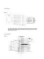
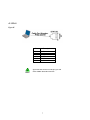
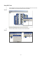
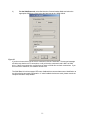
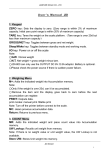
S200 Base Unit
Quick Start Guide
Part # M-S2-022-07
Initial Release
Revision A: 8/2008 S200 Revamp as Base Unit only guide
NOTE: This is a Quick Start Guide.
For a full Installation Manual visit our website http://www.danahermotion.com/documents or
browse the Product Support Package CD-ROM shipped with your product to find the complete
installation manual.
1.) Use the appropriate software. The software can be installed using the included CD ROM.
a.) If you are using the base unit or SynqNet option, use S200 Tools.
b.) If you are using the S200 Position Node with CANopen use S200 OC Tools.
Keep all product manuals as a product component during the life span of the servo drive. Pass
all product manuals to future users/owners of the servo drive.
NOTE
This is a Quick Start Guide and only contains
the minimum requirements to get the
drive/motor operational.
Helping you build a better machine faster.
Copyright Information
© Copyright 2006 Danaher Motion – All rights reserved.
Printed in the United States of America
Notice
Not for use or disclosure outside of Danaher Motion except under written agreement. All rights are reserved. No part of this book shall be
reproduced, stored in retrieval form, or transmitted by any means, electronic, mechanical, photocopying, recording, or otherwise without the
written permission from the publisher. While every precaution has been taken, the publisher assumes no responsibility for errors or omissions.
Neither is any liability assumed for damages resulting from the use of the information contained herein.
This document is proprietary information of Danaher Motion that is furnished for customer use ONLY. Information in this document is subject
to change without notice and does not represent a commitment on the part of Danaher Motion. Therefore, information contained in this manual
may be updated from time-to-time due to product improvements, etc., and may not conform in every respect to former issues.
Danaher Motion reserves the right to make engineering refinements on all its products. Such refinements may affect information in instructions.
Safety
WARNING
READ these instructions before connecting power. Damage can result
from MISWIRING at the power terminals.
DANGEROUS voltages are present on power input and motor output
terminals.
Only qualified personnel are permitted to transport, assemble, commission, and maintain this equipment. Properly
qualified personnel are persons who are familiar with the transport, assembly, installation, commissioning and
operation of motors, and who have the appropriate qualifications for their jobs.
Read all available documentation before assembling and using. Incorrect handling of products described in this
manual can result in injury and damage to people and/or machinery. Strictly adhere to the technical information
regarding installation requirements.
Keep all covers and cabinet doors shut during operation.
Be aware that during operation, the product has electrically charged components and hot surfaces. Control and power cables can carry a
high voltage, even when the motor is not rotating.
Never disconnect or connect the product while the power source is energized.
After removing the power source from the equipment, wait at least 5 minutes before touching or disconnecting sections of the equipment
that normally carry electrical charges (e.g., capacitors, contacts, screw connections). To be safe, measure the electrical contact points to
each other and to electrical safety earth with a meter before touching the equipment.
2
Figure A
AC Unit
Base Unit
STATUS
1
S
E
RJ
IA 5
L
6
9
2
8
C
O
M
MJ
A4
N
D
I/
O
1
9
1
1
F
E
E
DJ
B3
A
C
K
6
1
P
E
M
OJ
T2
O
R
W
V
4
U
1
P
E
A
-B
A
C
PJ
O1
W
E
R
+
B
C
2
C
1
L
3
L
2
S200 SERIES
9
L
1
PE
DC Unit
Base Unit
ST AT US
1
S
E
R J
IA 5
L
6
9
C
O
M
M
AJ
4
N
D
I/
O
2
8
1
9
1
5
1
1
P
E
W
V
U
F
6 E
E
DJ
B3
A
C
K
1
M
OJ
T 2
O
R
4
1
D
C
P J
W 1
R
3
S
2
0
0
S
E
R
IE
S
Note: This is a quick start guide for the S200 Base model only. Please visit
http://www.danahermotion.com/documents for quick start guides and installation manuals for
CANopen or SynqNet S200 drive models.
3
Connector Wiring
J1 AC POWER (S20260-, S20360-, S20660-VTS)
Figure B
Note: Please see the manual for complete required resistor characteristics.
J1 and TB1 AC POWER (S21260-, S22460-VTS)
Figure C
S
1
Motor
PE W
V
U
240/120 VAC HOT
L2
L1
10
240/120 VAC NEUTRAL
AC Power
240 VAC
L3
240/120 VAC
47-63 Hz
+B
+BUS
-B
-BUS
TB1
A
REGEN
Optional External
Regen Resistor
S200
J1
PE
1 AC Power 3
PE C2 C1
CTRL
VAC
CTRL
VAC
240/120 VAC
47-63 Hz
Note: Please see the manual for complete required resistor characteristics.
4
J1 DC POWER
Figure D
J2 MOTOR
Figure E
The cable shielding shown on the motor cable is for an individual cable. Danaher
Motion also offers combined motor and feedback cables. Please consult your sales
representative for details.
5
J3 FEEDBACK
Figure F
The cable shielding shown on the feedback cable is for and individual cable. Danaher
Motion also offers combined motor and feedback cables. Please consult your sales
representative for details.
J4 Command I/O
Figure G
J4 COMMAND I/O
9
18
I/O RTN
Analog Command Input -
26
8
25
17
7
16
Analog Command Input +
I/O RTN
Channel B Encoder Output/Input
Channel B Encoder Output/Input
24
6
15
23
5
14
22
4
13
21
3
12
Channel A Encoder Output/Input
Channel A Encoder Output/Input
20
2
11
19
1
10
6
DOUT2+ (RUN)
Encoder Output Channel Z
DOUT2Encoder Output Channel Z
DOUT1+ (Fault)
I/O RTN
DOUT1DAC MON2
MSINP1 (Direction)
DAC MON1
DINP3 (INHIBIT -)
I/O RTN
DINP2 (INHIBIT +)
SFD BAT+
DINP1 (ENABLE)
HSINP1DINP COM
HISINP1+ (Step/PWM)
J5 SERIAL
Figure H
Pin
J5-1
J5-2
J5-3
J5-4
J5-5
J5-6
NOTE
Description
No Connection
RX232
I/O RTN
I/O RTN
TX232
No Connection
If your PC does not have a serial port, you will
need a USB to Serial Port converter.
7
SWITCHES
Figure I
NOTE
The most significant digit, S2, is located above
S1.
S2 is a 4-position dipswitch. Switch positions 1 and 2 can set the operational mode
and feedback types when enabled. Setting the drive parameters as shown in the
following table enables the switch and is the factory default configuration. Switch
positions 3 and 4 are reserved for future functionality and should be left in the
down/closed factory default position.
Figure J
Switch
Position
S2-1
S2-2
S2-3
S2-4
Parameter
Setting
OpMode=
SetupS2-1
CommMode=
SetupS2-2
Function
Operational
Mode
Feedback
Type
Reserved
Reserved
Switch State
Down/Closed
Torque/Current
Control
SFD
Up/Open
Velocity
Control
6-Step
Default
Default
Reserved
Reserved
Switch S1 is a 10 position rotary switch. The function of switch S1 depends on the
feedback mode in which the drive is configured. Please see the S200 Reference
Manual available on http://www.danahermotion.com/documents
8
Getting Started
Complete instructions are contained in the following additional manuals:
S200 High Performance Compact Brushless Servo Drives SynqNet and Base Units manual
This manual is located on both the Product Support Package shipped with your product and the Danaher
website www.danahermotion.com.
1. Connect POWER (J1).
a. AC Unit: Be sure you have the control logic connected (C1, C2), the Bus Power (L1, L2,
L3), and PE (see diagram).
b. DC Unit: Be sure that PE and Control Power are wired to this connector (see diagram).
2. Connect MOTOR (J2). Review the appropriate wiring diagram for details.
3. Connect FEEDBACK (J3).
4. Connect COMMAND I/O (J4). Wire according to the diagram below to provide an enable signal.
Figure J
5. Connect J5, SERIAL to your computer using a RS-232 cable (part number (P7S2-232-9D).
6. Install Software using S200 Tools. For more information about installation, please visit
http://www.danahermotion.com/documents
7. Ensure that the enable input to J4 pin 1,2 is open circuited/unpowered. Now power the unit up.
9
Using S200 Tools
1)
Start the S200 Tools. The green status LED near J5 will flash at about a 2 Hz rate if the
drive is disabled or will be solid (not flash) if the drive is enabled.
Figure K
2)
Select the Utilities toolbar and open the Communication Wizard.
Figure L
10
3)
For the S200 Base unit, select Serial as the Communications Mode and select the
appropriate COM port. Note: Leave the baud rate at the 19200 default.
Figure M
If you do not know which type of drive is connected, click the Test button. The returned message
will either say that there is no connection, or tell you that the connected node is NOT an S200
drive. If there is no connection, confirm that you have an S200 drive at check connections. If you
do not have an S200 drive, the software will not work.
The S200 Base Unit drives support SFD motor feedback that communicates motor identification to
the drive allowing automatic configuration. If other feedback devices are used, please consult the
complete manual for setup details.
11
Jog the Motor
Select Status in the file tree on the left side of S200 Tools.
WARNING
Before turning the motor on, be sure the motor is safe to move and that the
motor is clear to turn with no obstructions.
Enable the drive (turn on input 1). You can verify that the drive is enabled if you see the green light at the
bottom of your screen (circled in red in Figure N.)
Figure N
Check the Fault Status and make sure it indicates “No Fault.” (Highlighted by the red rectangle in Figure
N.) If a fault is indicated, refer to the fault section “Chapter 11 Diagnostics and Troubleshooting” of the
“S200 High Performance Compact Brushless Servo Drives SynqNet and Base Units” located under
http://www.danahermotion.com/documents.
12
1)
In the file tree on the left hand side, select Status.
Figure O
2)
Under the Selected Variable View use the down arrow to select OpMode.
Figure P
13
3) Set OpMode to Velocity. If the middle column does not display velocity, select change and
set to Velocity.
Figure Q
4) On the next line of Selected Variable View, use the down arrow to select CmdSrc. Set this
variable to “Command Variable”. If it does not auto-populate, click on the Change button for
the CmdSrc line and change the option to Command Variable.
WARNING
The motor shaft will rotate during step 5.
5) On the third line of Selected Variable View, use the down arrow to select Command. This
field should auto populate 0 RPM. Click on the Change button and enter a desired test
velocity in the field. When you click on OK, the motor will turn.
6) To stop motor movement, click Change and return the RPM back to 0 and then select OK.
Use NV Save if the settings are needed after a power cycle!
Select Velocity ONLY to view the speed of the motor!
The system test is now complete. You may now configure the drive for your application
requirements and integration.
14
Sales and Service
Danaher Motion is committed to quality customer service. Our products are available worldwide through an extensive
authorized distributor network. To serve in the most effective way, please contact your local sales representative for
assistance. If you are unaware of your local sales representative, please contact us.
Europe
Danaher Motion Customer Service Europe
Email:
Phone:
Fax:
Web:
[email protected]
+49(0)203 9979 9
+49(0)203 9979 155
www.DanaherMotion.net
North America
Danaher Motion Customer Service North America
Email:
Phone:
Fax:
Web:
[email protected]
1-540-633-3400
1-540-639-4162
www.DanaherMotion.com
Helping you build a better machine faster.
15