1
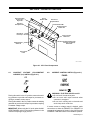
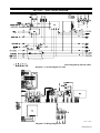
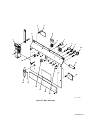
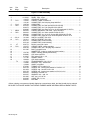
July 1993 Form: OM-880B Effective With Serial No. JJ490601 OWNER’S MANUAL CV-2 Control Option Constant Voltage Control For Big 30, 30A, 40, And 50 Diesels, And Big 40G Models For SMAW, GMAW, FCAW, And GTAW Welding 100% Duty Cycle At Welding Generator Rated Load Adapter And Extension Cords May Be Needed Read and follow these instructions and all safety blocks carefully. Give this manual to the operator. Have only trained and qualified persons install, operate, or service this unit. For help, call your distributor Call your distributor if you do not understand the directions. or: MILLER Electric Mfg. Co., P.O. Box 1079, Appleton, WI 54912 414-734-9821 cover 6/93 – ST-111 216-A PRINTED IN USA From Miller to You Thank you and congratulations on choosing Miller. Now you can get the job done and get it done right. We know you don’t have time to do it any other way. That’s why when Niels Miller first started building arc welders in 1929, he made sure his products offered long-lasting value and superior quality. Like you, his customers couldn’t afford anything less. Miller products had to be more than the best they could be. They had to be the best you could buy. Today, the people that build and sell Miller products continue the tradition. They’re just as committed to providing equipment and service that meets the high standards of quality and value established in 1929. This Owner’s Manual is designed to help you get the most out of your Miller products. Please take time to read the Safety precautions. They will help you protect yourself against potential hazards on the worksite. We’ve made installation and operation quick and easy. With Miller you can count on years of reliable service with proper maintenance. And if for some reason the unit needs repair, there’s a Troubleshooting section that will help you Miller is the first welding figure out what the problem is. The parts list equipment manufacturer in will then help you to decide which exact part the U.S.A. to be registered to the ISO 9001 Quality System you may need to fix the problem. Warranty and Standard. service information for your particular model are also provided. Miller Electric manufactures a full line of welders and welding related equipment. For information on other quality Miller products, contact your local Miller distributor to receive the latest full line catalog or individual catalog sheets. To locate your nearest distributor or service agency call 1-800-4-A-Miller, or visit us at www.MillerWelds.com on the web. Working as hard as you do – every power source from Miller is backed by the most hassle-free warranty in the business. Miller offers a Technical Manual which provides more detailed service and parts information for your unit. To obtain a Technical Manual, contact your local distributor. Your distributor can also supply you with Welding Process Manuals such as SMAW, GTAW, GMAW, and GMAW-P. TABLE OF CONTENTS Section No. Page No. SECTION 1 – SAFETY PRECAUTIONS AND SIGNAL WORDS 1-1. 1-2. General Information And Safety . . . . . . . . . . . . . . . . . . . . . . . . . . . . . . . Safety Alert Symbol And Signal Words . . . . . . . . . . . . . . . . . . . . . . . . . 1 1 SECTION 2 – SPECIFICATIONS 2-1. 2-2. Volt-Ampere Curves . . . . . . . . . . . . . . . . . . . . . . . . . . . . . . . . . . . . . . . . . Description . . . . . . . . . . . . . . . . . . . . . . . . . . . . . . . . . . . . . . . . . . . . . . . . . 3 3 SECTION 3 – INSTALLATION OR RELOCATION 3-1. 3-2. 3-3. CV-2 Installation . . . . . . . . . . . . . . . . . . . . . . . . . . . . . . . . . . . . . . . . . . . . . Remote-5 Receptacle Information And Connections . . . . . . . . . . . . . . Remote-14 Receptacle Information And Connections . . . . . . . . . . . . . 3 8 8 SECTION 4 – OPERATOR CONTROLS 4-1. 4-2. 4-3. 4-4. 4-5. Constant Voltage (CV)/Constant Current (CC) Switch . . . . . . . . . . . . . Current Control Switch . . . . . . . . . . . . . . . . . . . . . . . . . . . . . . . . . . . . . . . Output/Contactor Switch . . . . . . . . . . . . . . . . . . . . . . . . . . . . . . . . . . . . . . AC/DC Selector Switch . . . . . . . . . . . . . . . . . . . . . . . . . . . . . . . . . . . . . . . Circuit Breaker For Control Circuitry . . . . . . . . . . . . . . . . . . . . . . . . . . . . 12 12 13 13 13 SECTION 5 – SEQUENCE OF OPERATION 5-1. 5-2. 5-3. 5-4. Gas Metal Arc (GMAW) And Flux Cored Arc Welding (FCAW) . . . . . Shielded Metal Arc Welding (SMAW) . . . . . . . . . . . . . . . . . . . . . . . . . . . Gas Tungsten Arc Welding (GTAW) . . . . . . . . . . . . . . . . . . . . . . . . . . . . Shutting Down . . . . . . . . . . . . . . . . . . . . . . . . . . . . . . . . . . . . . . . . . . . . . . 14 15 15 16 SECTION 6 – MAINTENANCE & TROUBLESHOOTING 6-1. 6-2. 6-3. 6-4. 6-5. Routine Maintenance . . . . . . . . . . . . . . . . . . . . . . . . . . . . . . . . . . . . . . . . . Resetting Circuit Breakers . . . . . . . . . . . . . . . . . . . . . . . . . . . . . . . . . . . . Circuit Board PC3 Or PC4 Replacement Procedure . . . . . . . . . . . . . . Tungsten Electrode . . . . . . . . . . . . . . . . . . . . . . . . . . . . . . . . . . . . . . . . . . Troubleshooting . . . . . . . . . . . . . . . . . . . . . . . . . . . . . . . . . . . . . . . . . . . . . 17 17 17 18 20 SECTION 7 – ELECTRICAL DIAGRAM Diagram 7-1. Circuit Diagram For CV-2 . . . . . . . . . . . . . . . . . . . . . . . . . . . . . . . Diagram 7-2. Wiring Diagram . . . . . . . . . . . . . . . . . . . . . . . . . . . . . . . . . . . . . . . . 22 22 SECTION 8 – PARTS LIST Figure 8-1. Main Assembly . . . . . . . . . . . . . . . . . . . . . . . . . . . . . . . . . . . . . . . . . . 24 LIST OF CHARTS AND TABLES Table 2-1. Specifications . . . . . . . . . . . . . . . . . . . . . . . . . . . . . . . . . . . . . . . . . . . . Chart 2-1. DC Volt-Ampere Curves (CV Mode) . . . . . . . . . . . . . . . . . . . . . . . . . Chart 2-2. AC Volt-Ampere Curves (Single-Phase, CC Mode) . . . . . . . . . . . . Table 6-1. Maintenance Schedule . . . . . . . . . . . . . . . . . . . . . . . . . . . . . . . . . . . . Table 6-2. Tungsten Electrode Size . . . . . . . . . . . . . . . . . . . . . . . . . . . . . . . . . . . Table 6-3. Troubleshooting . . . . . . . . . . . . . . . . . . . . . . . . . . . . . . . . . . . . . . . . . . 1 2 2 17 19 21 OM-880B – 7/93 SECTION 1 – SAFETY PRECAUTIONS AND SIGNAL WORDS 1-1. GENERAL INFORMATION AND SAFETY 1-2. A. General SAFETY ALERT SYMBOL AND SIGNAL WORDS The following safety alert symbol and signal words are used throughout this manual to call attention to and identify different levels of hazard and special instructions. Information presented in this manual and on various labels, tags, and plates on the unit pertains to equipment design, installation, operation, maintenance, and troubleshooting which should be read, understood, and followed for the safe and effective use of this equipment. This safety alert symbol is used with the signal words WARNING and CAUTION to call attention to the safety statements. The nameplate of this unit uses international symbols for labeling the front panel controls. The symbols also appear at the appropriate section in the text. WARNING statements identify procedures or practices which must be followed to avoid serious personal injury or loss of life. B. Safety The installation, operation, maintenance, and troubleshooting of arc welding equipment requires practices and procedures which ensure personal safety and the safety of others. Therefore, this equipment is to be installed, operated, and maintained only by qualified persons in accordance with this manual and all applicable codes such as, but not limited to, those listed at the end of Arc Welding Safety Precautions in the welding generator Owner’s Manual. CAUTION statements identify procedures or practices which must be followed to avoid minor personal injury or damage to this equipment. IMPORTANT statements identify special instructions necessary for the most efficient operation of this equipment. SECTION 2 – SPECIFICATIONS Table 2-1. Specifications Model BIG 30 DIESEL And BIG 30A DIESEL Rated Output At 100% Duty Cycle* DC Load Voltage Range In CV Mode AC OpenVoltage Range In CC Mode* 200 Amperes At 28 Volts AC Amperage Range In CC Mode* Max. Open-Circuit Volts* Weight DC CV Mode AC CC Mode Net Ship 40 70 42 lbs. (19 kg) 47 lbs. (21 kg) 45-325 Amperes 10-35 40-70 BIG 40 DIESEL And BIG 40G 300 Amperes At 32 Volts 45-475 Amperes BIG 50 DIESEL 300 Amperes At 32 Volts 50-495 Amperes *See Owner’s Manual For DC Specifications In CC Mode OM-880 Page 1 Chart 2-1. DC Volt-Ampere Curves (CV Mode) A. BIG 30 DIESEL And BIG 30A DIESEL Models Chart 2-2. AC Volt-Ampere Curves (Single-Phase, CC Mode) A. BIG 30 DIESEL And BIG 30A DIESEL Models SB-111 309-A SB-111 680-B B. BIG 40 DIESEL And BIG 40G Models B. BIG 40 DIESEL And BIG 40G Models SB-111 679-A C. BIG 50 DIESEL Models C. BIG 50 DIESEL Models SB-111 678-A OM-880 Page 2 SB-111 313-B SB-111 317-A 2-1. VOLT-AMPERE CURVES (Charts 2-1 And 2-2) The volt-ampere curves show the output voltage and amperage of the welding generator available at any point from the minimum to maximum of each coarse amperage range. With the use of the volt-ampere curves it is possible to determine what the weld amperage will be at a particular arc voltage. The volt-ampere curves show the minimum and maximum curves of each coarse amperage range. 2-2. DESCRIPTION This Constant Voltage control panel is designed for use with the BIG 30 DIESEL, BIG 30A DIESEL, BIG 40 DIESEL, BIG 40G, and BIG 50 DIESEL welding generator models. The CV-2 expands capabilities of the welding generator to include constant voltage dc and single–phase ac weld output selections. A switch is provided for making the ac selection or for changing the dc polarity. In addition, the 5-socket and 14-socket Amphenol receptacles on this panel provide a junction point with the unit internal circuitry for connecting equipment used in Shielded Metal Arc (SMAW), Gas Metal Arc (GMAW), Flux Cored Arc (FCAW), and Gas Tungsten Arc (GTAW) Welding processes. A 1 ft. (254 mm) adapter cord with 2-prong and 3-socket plugs to a 14-pin Amphenol plug is required to provide CV-2 connection capability to wire feed equipment using an interconnecting cord with 2-socket and 3-prong twistlock plugs. Other adapter cords and extension cords with different plug combinations can be obtained for connecting various welding system devices and controls to the CV-2 receptacles. SECTION 3 – INSTALLATION OR RELOCATION IMPORTANT: If CV-2 was factory installed, proceed directly to Section 3-2. 3-1. CV-2 INSTALLATION 3. Loosen the clamp securing the air cleaner hose to the engine intake manifold and remove the hose from the manifold. 4. For BIG 40 DIESEL, BIG 40G, and BIG 50 DIESEL models: Loosen the clamp securing the muffler to the exhaust pipe, and remove the muffler from the unit. 5. Raise and slide cover with side doors approximately 1 ft. (0.3 m) back over radiator. WARNING: ELECTRIC SHOCK can kill. • Do not touch live electrical parts. • Stop engine, and disconnect negative (–) battery cable from battery before inspecting, maintaining, or servicing. MOVING PARTS can cause serious injury. • Keep away from moving parts such as fans, belts, and rotors. HOT ENGINE PARTS can cause severe burns. • Wear protective gloves and clothing when working on a hot engine. • Allow unit to cool down, if applicable, before beginning installation. Installation to be performed only by qualified persons. CAUTION: METAL FILINGS AND/OR TOOL CONTACT WITH INTERNAL COMPONENTS can damage unit. • Cover internal components. • 6. Clean unit, and remove internal covering material before resuming operation. On all welding generator models except BIG 30A DIESEL install key chain onto CV-2 panel as follows: A. Preparing Unit For Installation a. Drill out the pop rivet securing the key chain to the lower front panel. IMPORTANT: On all welding generator models except BIG 30A DIESEL, it is necessary to move the top cover back approximately 1 ft. (0.3 m) away from the front panel to gain access to components. b. Install and secure key with key chain onto CV-2 panel at the prepunched hole location (see Figure 4-1: hardware not supplied). 1. Remove all necessary top cover securing hardware and components. 7. Remove and discard lower front panel from unit; retain securing hardware. 2. Raise both side doors and tie together across the cover. 8. If applicable, disconnect electrode holder and work clamp cables from weld output terminals. OM-880 Page 3 Transformer T2 Installed Onto Base Mounting Strip Right Front Cover Of Unit BIG 30 DIESEL And BIG 30A DIESEL Transformer T2 Installation ST-145 421 Figure 3-1. Location For Transformer T2 Installation B. Transformer And Lower Panel Installation 1. Locate and install supplied transformer T2 onto the welding generator as follows: 1. Disconnect cable 30 from rear of Negative weld output terminal. a. For BIG 30 DIESEL and BIG 30A DIESEL models: Install T2 onto the right front portion of the base mounting strip at the prepunched hole locations (see Figure 3-1). Secure T2 with the four supplied 1/4-20 x 3/4 in. screws, flat washers, lockwashers, and nuts on BIG 30 DIESEL, but do not use flat washers and nuts on BIG 30A DIESEL. 2. Install a 6 in. (152 mm) long piece of supplied insulated tubing onto cable 30 disconnected in Step 1. b. For BIG 40 DIESEL, BIG 40G, and BIG 50 DIESEL models: Install the supplied mounting bracket onto T2, and secure bracket with the four supplied 1/4-20 x 3/4 in. screws, lock washers, and flat washer. Mount T2 with bracket onto fuel tank and reactor Z1 support angles (see Figure 3-5) with T2 located below right front corner of fuel tank. Secure mounting bracket to support angles with the three supplied 1/4-20 x 1/2 in. self-tapping screws. IMPORTANT: To ease CV-2 electrical connections, remove weld output terminal mounting bracket from left front upright Also, before securing CV-2 panel after installation, check for clearance between lugs of preinstalled cables on the AC/DC Selector switch terminals and any welding generator components. Reposition lugs at switch terminals as necessary to prevent contact between parts. 2. C. Electrical Connections Install and secure the supplied CV-2 panel onto the welding generator with the hardware removed in Step 7 of Section A. OM-880 Page 4 IMPORTANT: If unit is equipped with dc meters, connect negative (black) voltmeter lead at the connection point where cables 30 join together. Be sure that the voltmeter lead is installed last on top of the two cable terminal lugs. 3. Reconnect cable 30 to switch S1 cable 30 and secure with a supplied 1/4-20 x 1/2 in. flange screw and nut (see Figure 3-2). 4. Slide the installed tubing over connections, and secure with two supplied nylon cable ties (see Figure 3-2). 5. Disconnect cable 19 from rear of Positive weld output terminal. 6. Install the remaining 6 in. (152 mm) long piece of insulated tubing onto cable 19 disconnected in Step 5. 7. Reconnect cable 19 to switch S1 cable 19, and secure with a supplied 1/4-20 x 1/2 in. flange screw and nut (see Figure 3-2). 8. Slide the installed tubing over connection, and secure with two supplied nylon cable ties (see Figure 3-2). 9. Connect cable 28 from switch S1 to rear of Negative weld output terminal (see Figure 3-2). Rear View (Inside) Of Lower Front Panel Left Front Upright When Viewed From Front Of Control Panel Electrode (Negative) Weld Output Terminal Cable 28 Weld Output Terminal Assembly Work (Positive) Weld Output Terminal Cable 30 From Negative Weld Output Terminal And Black Voltmeter Lead, If Applicable Cable 30 Bimetal Jumper Bar-Copper Side Of Bar Against Terminal Surface Cable 19 From Positive Weld Output Terminal Cable Lug Connection With Tubing And Ties Selector Switch S1 Cable 19 SB-112 688-A Figure 3-2. Selector Switch S1 DC Connections WARNING: ELECTRIC SHOCK can kill; BIMETAL JUMPER BAR CONTACT WITH INTERNAL COMPONENTS can cause personal injury and equipment damage. • Do not touch live electrical parts. • Do not allow bimetal jumper bar to touch metal surfaces or internal components other than the intended connection. Route bimetal jumper bar so it is not touching other surfaces or components between connection points during operation. IMPORTANT: Be sure that copper side of bimetal jumper bar is in contact with copper surface of output terminal when making connections. 10. 11. c. 12. Route cables over top of stator barrel and to right side of unit. Connect cables from S1 to rectifier SR3 with existing cables 17 and 27 below right rear corner of the fuel tank (see Figure 3-3). For BIG 40 DIESEL, BIG 40G, and BIG 50 DIESEL models, connect cables 17 and 27 from CV-2 Selector switch S1 as follows: a. Route cables from S1 up to range switch S3. b. Connect S1 cables with existing cables 17 and 27 at appropriate terminals on S3 (see Figure 3-3). 13. Connect lead 100 from installed transformer T2 to terminal D on CV-2 terminal strip 3T (see Parts List view for CV-2 component locations). 14. Connect lead 205 from T2 to piggyback connector on existing lead 205 at CV/CC switch S12 on CV-2 panel (see Parts List view for CV-2 component locations). a. Locate and install supplied cables 17 and 27 on existing cables 17 and 27 on S1. Be sure that the lugs on the nonconnected ends of the supplied cables have the larger diameter hole. Secure the cable lug connections using the supplied 1/4-20 x 3/4 in. screws, flat washers (4), and nuts. 15. Connect lead 206 from T2 to the unused terminal at circuit breaker CB6 on CV-2 panel (see Parts List view for CV- component locations). 16. Locate leads 623, 625, 628, 632, and 634 hanging from Current Regulator box on rear of front panel. Cut and remove nylon cable ties holding leads together (see Figure 3-4). b. Slide a 6 in. (152 mm) long piece of supplied insulated tubing over each connection. Secure insulated tubing with the supplied nylon cable ties. 17. Disconnect leads 628 and 634 at insulated friction terminals, and connect these leads to the matching leads from the CV-2 panel (see Figure 3-4). Connect bimetal jumper bar from switch S1 to rear of Positive weld output terminal (see Figure 3-2). For BIG 30 DIESEL and BIG 30A DIESEL models, connect cables 17 and 27 from CV-2 Selector switch S1 as follows: OM-880 Page 5 FRONT FRONT Rectifier SR3: Connect CV-2 Leads 17 And 27 With Existing Leads On SR3 Range Switch S3: Connect CV-2 Leads 17 And 27 With Existing Leads On SR3 BIG 30 DIESEL And BIG 30A DIESEL Rectifier SR3 BIG 40 DIESEL, BIG 40G, And BIG 50 DIESEL Rear View Of Range Switch ST-145 422 / ST-145 423 Figure 3-3. Selector Switch S1 AC Connections Lead 628 Current Regulator Box Lead 634 Lead 632 Lead 623 Nameplate Lead 625 Leads From CV-2 Control Lead 623 Lead 632 Lead 634 Lead 628 SC-111 077-A Figure 3-4. Lead Connections From CV-2 To Current Regulator Circuitry OM-880 Page 6 18. Disconnect leads 623 and 625 at insulated friction terminals, and connect these leads to the matching leads from the CV-2 panel (see Figure 3-4). 19. Connect lead 632 from Current Regulator box to lead 632 from CV-2 panel (see Figure 3-4). 20. Connect lead 49 from CV-2 panel to terminal at AUTO IDLE switch S4 on BIG 30 DIESEL, BIG 40 DIESEL, BIG 40G, and BIG 50 DIESEL models or to terminal at Engine Control switch S1 on BIG 30A DIESEL models where existing lead 49 is connected as follows: b. Connect the insulated male friction terminal on CB5 lead 110 to female friction terminal on end of lead 110 disconnected in Step a. c. For welding generators equipped with auxiliary power circuit breaker CB3, proceed as follows: a. Disconnect existing lead 110 from CB3. b. Connect the insulated male friction terminal on CB5 lead 110 to female friction terminal on end of lead 110 disconnected in Step a. a. Disconnect existing lead 49 from S4 or S1. c. b. Reconnect lead 49 (from Step a) to piggyback connector on lead 49 from CV-2 panel. c. 21. Install piggyback connector onto S4 or S1 terminal where lead 49 was removed in Step a. 23. Connect lead 42 from CV-2 panel to the rear of the equipment grounding terminal located in the lower right portion of the front control panel on the welding generator. Connect the two leads 100 from terminal strip 3T on CV-2 panel to lead 100 at the 120V duplex receptacle as follows: b. Connect the insulated female friction terminal on 3T lead 100 with the male friction terminal on the end of lead 100 separated in Step a. Connect leads 110 from CV-2 panel circuit breaker CB5 as follows: c. For welding generators not equipped with auxiliary power circuit breaker CB3, proceed as follows; a. Locate and disconnect the friction terminal connection between leads 110 and 112 near the rear of the 120V duplex receptacle. Connect remaining CB5 lead 110 to CB3 terminal where lead 110 was disconnect in Step a. a. Locate and disconnect the friction terminal connection on lead 100 near the rear of the 120V duplex receptacle. IMPORTANT: Be sure that all existing leads remain connected to the equipment grounding terminal when connecting lead 42 from CV-2 panel. 22. Connect remaining CB5 lead 110 to lead 112 disconnected in Step a. 24. Connect the remaining male friction terminal on 3T lead 100 with the female friction terminal on the end of the remaining lead 100 separated in Step a. Tape or tie leads from CV-2 components to existing wiring harness to maintain lead dress and to avoid contact with hot or moving parts. OM-880 Page 7 Welding Generator Frame LEFT Install Switch Guard Onto Lower Front Portion Of Base Just Below New Lower Front Panel Big 40 Diesel, Big 40G, And Big 50 Diesel Transformer Mounting Bracket Transformer T2 Switch Guard (Angle Bracket) RIGHT FRONT Use Switch Guard As Template To Mark Hole Locations SB-112 332-A Figure 3-5. Location For Switch Guard Installation D. Switch Guard Installation (Figure 3-5) 2. IMPORTANT: Switch guard installation is only necessary on welding generators without this bracket installed from the factory. Affix supplied ELECTRODE label over NEGATIVE designation for weld output terminal. 3. Affix supplied WORK label over POSITIVE designation for weld output terminal. 4. Connect weld cables to weld output terminals as follows: Electrode holder cable to weld output terminal labeled ELECTRODE, and work clamp cable to weld output terminal labeled WORK. 1. Locate the supplied switch guard (angle bracket), and using the guard as a template, mark the two mounting hole locations onto lower front portion of the welding generator base as shown in Figure 3-5. CAUTION: METAL FILINGS AND/OR TOOL CONTACT WITH INTERNAL COMPONENTS can damage unit. • Cover internal components. • 2. 3. 5. Clean unit, and remove internal covering material before resuming operation. Drill 9/32 in. (7 mm) diameter hole at each marked location. Reinstall weld output terminal bracket onto left front upright. IMPORTANT: To ease reinstalling of the weld output terminal bracket, position cables 19 and 30 below the bottom edge of the bracket so that the cables are routed along the left side of the stator barrel. Also, check the bimetal jumper bar connection at the rear of the weld output terminal after reinstalling the bracket; tighten the bimetal jumper bar securing hardware if necessary. OM-880 Page 8 On all welding generator models except BIG 30A DIESEL, reinstall components as follows: a. Reinstall and secure top cover. b. Reinstall and secure the air cleaner hose onto the engine intake manifold. 6. On BIG 40 DIESEL, BIG 40G, and BIG 50 DIESEL models: Reinstall and secure the muffler onto the exhaust pipe. 7. Close and secure both side doors. Install and secure the switch guard with the two supplied 5/16-18 x 3/4 in. self-forming screws. E. Final Procedure 1. IMPORTANT: Once weld cables are connected to the unit, the Selector Switch position provides the desired DC polarity or AC to the weld output terminals. 3-2. REMOTE-5 RECEPTACLE INFORMATION AND CONNECTIONS (Figure 3-6 And 4-1) REMOTE-5 The 5-socket REMOTE-5 receptacle RC3 provides a junction point for connecting a Remote Contactor and/or Amperage or Voltage Control to the control circuitry of the welding power source. To connect the Remote Contactor and/or Amperage or Voltage Control to the REMOTE-5 receptacle, align keyway, insert plug from the Remote Control, and rotate threaded collar fully clockwise. A C D J K B L I N H M E G F E A D B C S-0004 Figure 3-7. Front View Of 14-Socket Amphenol Receptacle With Socket Designations S-0005 Figure 3-6. Front View Of 5-Socket Amphenol Receptacle With Socket Designations The command signals required and the output signals available at the sockets of receptacle RC4 by means of the welding generator control circuitry are as follows: Socket A: Up to 10 amperes of 24 volts ac 60 Hz with respect to socket G (circuit common), protected by circuit breaker CB6. Receptacle RC3 socket connections to the welding power source control circuitry are as follows: Socket B: Weld contactor control for 24 volts ac wire feeders providing contact closure to socket A. Socket A: Contactor control switch connection. Socket C: Socket B: Contactor control switch connection. Socket C: Amperage or voltage control connection (maximum side). 0 to +10 volts dc with respect to Socket D; reference voltage for output command signal depends on the AMPERAGE & VOLTAGE ADJUSTMENT control setting on the unit. Socket D: Control circuit common for remote control device. Socket D: Amperage or voltage control connection (minimum side). Socket E: Socket E: Amperage or voltage control connection (wiper contact). Output command signal to wiper of remote control potentiometer, 0 volts equals machine minimum; +10 volts equals machine maximum. Socket F: Not used. IMPORTANT: Use only one CV-2 receptacle at a time for remote current and/or voltage control or welding generator may not work properly. 3-3. Socket G: 24 and 120 volts ac circuit common. Socket H: Not used. Socket I: Up to 10 amperes of 120 volts ac 60 Hz with respect to socket G (circuit common), protected by circuit breaker CB5. Socket J: Weld contactor control for 120 volts ac wire feeders providing contact closure to socket I. Socket K: Machine chassis. Socket L: Not used. REMOTE-14 RECEPTACLE INFORMATION AND CONNECTIONS (Figures 3-7 And 4-1) REMOTE-14 The 14-socket REMOTE-14 receptacle RC4 provides a junction point for connecting a Remote Amperage/Voltage Control and/or a Remote Contactor Control or a wire feeder providing switch closure for contactor control to the control circuitry of the welding generator. To make connections, align keyway, insert plug fully into receptacle, and rotate threaded collar clockwise. Socket M: Not used. Socket N: Not used. IMPORTANT: Use only one CV-2 receptacle at a time for remote current and/or voltage control or welding generator may not work properly. OM-880 Page 9 Work Electrode Holder Welding Generator Optional Remote Contactor And Amperage Control Connection To CV-2 5-Socket Amphenol Receptacle RC3 SA-112 730 Figure 3-8. Connection Diagram For Remote Control Using 5-Socket Amphenol Receptacle RC3 Electrode Cable Work Connection To CV-2 14-Socket Amphenol Receptacle RC4 Welding Generator Spoolmatic 3 Gun/Feeder Gas Supply With Flowmeter And Regulator SA-112 732 Gas Hose Figure 3-9. Connection Diagram For Spoolmatic 3 Using 14-Socket Amphenol Receptacle RC4 Work Wire Drive Assembly Welding Gun S-32 Type Wire Feeder With 12VDC Optional Shielding Gas Valve, Remote Contactor, And Voltage Control 3 ft. (914 mm) Long Pigtail With Amphenol Electrode Cable Welding Generator Connection To CV-2 14-Socket Amphenol Receptacle RC4 - Use 14-Pin To 14-Pin Interconnecting Cord Gas Hose Gas Supply With Flowmeter And Regulator SA-112 735 Figure 3-10. Connection Diagram For S-32P Type Wire Feeders Using 14-Socket Amphenol Receptacle RC4 OM-880 Page 10 Wire Drive Assembly Work Welding Gun Porta-Mig Model Wire Feeder Electrode Cable Welding Generator Connection To CV-2 14-Socket Amphenol Receptacle RC4 - Use 14-Pin To 14-Pin Interconnecting Cord Gas Supply With Flowmeter And Regulator Gas Hose SA-112 734 Figure 3-11. Connection Diagram For Porta-Mig Type Wire Feeders Using 14-Socket Amphenol Receptacle RC4 Work Electrode Cable 115 VAC Input Cord Connected To Unit Duplex Receptacle RC1 Torch/Gun HF-251 Model High-Frequency Unit Remote Contactor Amperage Control With 20 ft. (6 m) Long Cord Welding Generator Connection To CV-2 5-Socket Amphenol Receptacle RC3 – Use 5-Pin To 5-Pin Interconnecting Cord Gas Supply With Flowmeter And Regulator Gas Hose SA-112 733-A Figure 3-12. Connection Diagram For HF-251 Model High-Frequency Unit Using 5-Socket Amphenol Receptacle RC3 Work Welding Gun Wire Drive Assembly 50 Series Model Wire Feeder Interconnecting Cord Supplied With Feeder Electrode Cable Welding Generator Connection To CV-2 14-Socket Amphenol Receptacle RC4 - Use 14-Pin To 2-Prong And 3-Socket Twistlock Receptacle Adapter Cord Gas Hose Gas Supply With Flowmeter And Regulator SA-112 731 Figure 3-13. Connection Diagram For 50 Series Type Wire Feeders Using Adapter Cord For Connection To 14-Socket Amphenol Receptacle RC4 OM-880 Page 11 Work Welding Gun Wire Drive Assembly Electrode Cable Welding Generator 50 Series Wire Feeder Connection To CV-2 14-Socket Amphenol Receptacle RC4 - Use 14-Pin To 14-Pin Interconnecting Cord Gas Hose Gas Supply With Flowmeter And Regulator SA-112 734 Figure 3-14. Connection Diagram For 50 Series Wire Feeder Using 14-Socket Amphenol Receptacle RC4 OM-880 Page 12 SECTION 4 – OPERATOR CONTROLS Prepunched Hole For Securing Key Chain Circuit Breaker CB5 Remote-14 Receptacle RC4 Remote-5 Receptacle RC3 Circuit Breaker CB6 Output/Contactor Switch S10 Receptacle Dust Cups Current Control Switch S11 Constant Voltage (CV)/ Constant Current(CC) Switch S12 AC/DC Selector Switch S1 CV-2 Control Panel SC-111 216-A Figure 4-1. CV-2 Panel Components 4-1. CONSTANT VOLTAGE (CV)/CONSTANT CURRENT (CC) SWITCH (Figure 4-1) 4-2. CURRENT CONTROL SWITCH (Figure 4-1) PANEL CC A V CURRENT CONTROL REMOTE CV Placing this switch in the CC position causes the welding generator to provide weld output for processes requiring a constant current output. Placing this switch in the CV position causes the welding generator to provide weld output for processes requiring a constant voltage output. IMPORTANT: When using the CV mode, place the AMPERE RANGES switch on the welding generator in the maximum amperage range position. WARNING: ELECTRIC SHOCK can kill. • Do not touch live electrical parts. • • Do not touch weld output terminals when contactor is energized. Do not touch welding wire or electrode and work clamp at the same time. If remote current or voltage control is desired, make connections to either the REMOTE-5 or REMOTE-14 receptacle as instructed in Section 3-2 or 3-3. Place the CURRENT CONTROL switch in the REMOTE position. OM-880 Page 13 When a Remote Current or Voltage Control is being used, the remote control functions as a fine amperage or voltage adjustment for the AMPERAGE & VOLTAGE adjustment control setting of the welding generator. For example: If the AMPERAGE & VOLTAGE adjustment control on the welding generator is set at midrange, the Remote Current or Voltage Control will provide (from minimum to maximum adjustment) fine amperage or voltage adjustment of one half of the welding generator output for the amperage range selected on the AMPERE RANGES switch. For complete remote control of the output, rotate the front panel AMPERAGE & VOLTAGE control to the maximum position. If remote current or voltage control is not desired, place the CURRENT CONTROL switch in the PANEL position. Only the front panel controls will then adjust the output. 4-3. 4-4. ELECTRODE POS. (+) ELECTRODE NEG. WARNING: ELECTRIC SHOCK can kill. • Do not use AC output in damp areas, if movement is confined, or if there is a danger of falling. • Use AC output ONLY if required for the welding process. • If AC output is required, use remote output control. • Read and follow Safety Precautions at beginning of welding generator Owner’s Manual. ON OUTPUT/ CONTACTOR REMOTE CAUTION: ARCING can damage switch contacts. • Do not change the position of the AC/DC Selector switch while welding or under load. WARNING: ELECTRIC SHOCK can kill. • Do not touch live electrical parts. • Do not touch weld output terminals when contactor is energized. Do not touch welding wire or electrode holder and work clamp at the same time. Arcing causes the contacts to become pitted and eventually inoperative. The Selector switch allows the operator to select DC ELECTRODE NEGATIVE (–), DC ELECTRODE POSITIVE (+), or AC without changing weld output connections. 4-5. When the OUTPUT/CONTACTOR switch is in the ON position, open-circuit voltage is present at the weld output terminals for as long as the engine is running. If remote contactor control is desired, make connections to either the REMOTE-5 or REMOTE-14 receptacle as instructed in Section 3-2 or 3-3. Place the OUTPUT/CONTACTOR switch in the REMOTE position. Open-circuit voltage is present at the weld output terminals when the Remote Contactor Control switch is closed. If remote contactor control is not desired, place the OUTPUT/CONTACTOR switch in the ON position. Open-circuit voltage will be available at the weld output terminals whenever the engine is running. OM-880 Page 14 AC (–) OUTPUT/CONTACTOR SWITCH (Figure 4-1) • AC/DC SELECTOR SWITCH (Figure 4-1) CIRCUIT BREAKER FOR CONTROL CIRCUITRY (Figure 4-1) CIRCUIT BREAKER Two circuit breakers, CB5 and CB6, are provided on the CV-2 panel. Circuit breaker CB5 protects the primary of transformer T2 and the unit wiring from overload and damage. If CB5 opens, there would be no 115 volts ac or 24 volts ac output and the wire feeder would stop. Circuit breaker CB6 protects transformer T2 and the unit wiring from overload and damage. If CB6 opens, there would be no 24 volts ac output and the wire feeder would stop if it was using 24 vac. For circuit breaker resetting and additional information, see Section 6-2. SECTION 5 – SEQUENCE OF OPERATION WARNING: ELECTRIC SHOCK can kill; MOVING PARTS can cause serious injury; IMPROPER AIRFLOW AND EXPOSURE TO ENVIRONMENT can damage internal parts. • Do not touch live electrical parts. • Stop engine, and disconnect negative (–) battery cable from battery before inspecting or servicing. • Keep away from moving parts such as fans, belts, and rotors. • Keep all covers and panels in place while operating. Warranty is void if the welding generator is operated with any portion of the outer enclosure removed. ARC RAYS can burn eyes and skin; NOISE can damage hearing. • Wear correct eye, ear, and body protection. FUMES AND GASES can seriously harm your health. • Ventilate to keep from breathing fumes and gases. • If ventilation is inadequate, use approved breathing device. • Use in open, well ventilated areas, or vent exhaust out of doors. WELDING WIRE can cause puncture wounds. • Do not point gun toward any part of the body, any conductive surface, or other personnel. HOT METAL, SPATTER, SLAG, EXHAUST can cause fire and burns. • Watch for fire. • • 5-1. Keep a fire extinguisher nearby, and know how to use it. Allow work and equipment to cool before handling. Do not spill fuel; if spilled, wipe up. Do not refuel if engine is hot or running. Do not refuel near sparks or open flame. Do not smoke while refueling. Do not fill tank to top; allow room for expansion. MAGNETIC FIELDS FROM HIGH CURRENTS can affect pacemaker operation. • Wearers should consult their doctor before going near arc welding, gouging, or spot welding operations. GAS METAL ARC (GMAW) AND FLUX CORED ARC WELDING (FCAW) WARNING: Read and follow safety information at beginning of entire Section 5 before proceeding. 1. Be sure that the welding generator has been prepared as instructed in its Owner’s Manual. 2. Install and connect CV-2 according to Section 3, if applicable. 3. Install and connect wire feeder to the appropriate CV-2 REMOTE-5 or REMOTE-14 receptacle according to Section 3 and wire feed equipment Owner’s Manual. 4. Select and obtain proper welding wire, and thread as instructed in wire feeder Owner’s Manual. 5. If shielding gas is required, make all the necessary connections. 6. Wear dry insulating gloves and clothing. 7. Connect work clamp to clean, bare metal at workpiece. 8. Rotate the AMPERE RANGES switch and AMPERAGE AND VOLTAGE ADJUSTMENT control to the desired position (see welding generator Owner’s Manual). AND ENGINE FUEL can cause fire or explosion. • Stop engine before checking or adding fuel. • • • • • See Arc Welding Safety Precautions in the welding generator Owner’s Manual for basic welding safety information. IMPORTANT: When using the CV mode, place the AMPERE RANGES switch on the welding generator in the maximum position, and use the AMPERAGE AND VOLTAGE ADJUSTMENT control to select the desired voltage. If remote voltage control is used, the minimum to maximum voltage range selection at the remote control will be a percentage of the AMPERAGE AND VOLTAGE ADJUSTMENT control setting (see Section 4-2). When using the CC mode, place the AMPERE RANGES switch and the AMPERAGE AND VOLTAGE ADJUSTMENT control on the welding generator in the desired positions. If remote amperage control is used, the minimum to maximum amperage range selection at the remote control will be a percentage of the AMPERAGE AND VOLTAGE ADJUSTMENT control setting (see Section 4-2). GMAW normally uses the CV mode; FCAW may use either CV or CC depending on the selected welding wire. 9. Place the CV-2 CV/CC switch in the proper position as determined by the selected welding process (see Section 4-1). OM-880 Page 15 10. 11. 12. If remote contactor control is not used, place the CV-2 OUTPUT/CONTACTOR switch in the ON position. If remote contactor control is to be used, place the OUTPUT/CONTACTOR switch in the REMOTE position (see Section 4-3). 3. Wear dry insulating gloves and clothing. 4. Select and obtain proper electrode. 5. Connect work clamp to clean, bare metal at workpiece. If remote amperage or voltage control is not used, place the CV-2 CURRENT CONTROL switch in the PANEL position. If remote amperage or voltage control is to be used, place the CURRENT CONTROL switch in the REMOTE position (see Section 4-2). 6. Rotate the AMPERE RANGES switch and AMPERAGE AND VOLTAGE ADJUSTMENT control to the desired position (see welding generator Owner’s Manual). 7. Place the CV-2 CV/CC switch in the CC position (see Section 4-1). Place the AC/DC Selector switch in the proper position as determined by the selected welding process (see Section 4-4). 8. If remote amperage control is not used, place the CV-2 CURRENT CONTROL switch in the PANEL position. If remote amperage control is to be used, place the CURRENT CONTROL switch in the REMOTE position (see Section 4-2). 9. Place the AC/DC Selector switch in the desired position (see Section 4-4). WARNING: ELECTRIC SHOCK can kill. • Do not use AC output in damp areas, if movement is confined, or if there is a danger of falling. • Use AC output ONLY if required for the welding process. • If AC output is required, use remote output control. • Read and follow Safety Precautions at beginning of welding generator Owner’s Manual. WARNING: ELECTRIC SHOCK can kill. • Do not use AC output in damp areas, if movement is confined, or if there is a danger of falling. • Use AC output ONLY if required for the welding process. • If AC output is required, use remote output control. • Read and follow Safety Precautions at beginning of welding generator Owner’s Manual. 13. Turn on shielding gas supply at the source, if applicable. 14. Start the engine as instructed in the welding generator Owner’s Manual. 15. Place the AUTO IDLE control switch in the OFF position or the Engine Control switch in the RUN position (see welding generator Owner’s Manual). 10. Place the CV-2 OUTPUT/CONTACTOR switch in the ON position (see Section 4-3). 11. Start the engine as instructed in the welding generator Owner’s Manual. IMPORTANT: Power requirements by CV-2 components will cause the welding generator engine to operate at weld rpm continuously in the CV mode if the AUTO IDLE control switch is placed in the ON position or the Engine Control switch is placed in the AUTO IDLE position. Placing the AUTO IDLE control switch in the OFF position or the Engine Control switch in the RUN position will prevent mistaking unit operation as a malfunction in the Auto Idle circuitry. 12. Place the AUTO IDLE control switch or Engine Control switch in the desired position (see welding generator Owner’s Manual). 13. Insert electrode into holder. 14. Wear welding helmet with proper filter lens according to ANSI Z49.1. 15. Begin welding. 16. Wear welding helmet with proper filter lens according to ANSI Z49.1. 17. Begin welding. 5-2. 5-3. GAS TUNGSTEN ARC WELDING (GTAW) WARNING: Read and follow safety information at beginning of entire Section 5 before proceeding. SHIELDED METAL ARC WELDING (SMAW) 1. WARNING: Read and follow safety information at beginning of entire Section 5 before proceeding. Be sure that the welding generator has been prepared as instructed in its Owner’s Manual. 2. Install and connect CV-2 according to Section 3, if applicable. 1. Be sure that the welding generator has been prepared as instructed in its Owner’s Manual. 3. Install torch/gun according to the manufacturer’s Owner’s Manual. 2. Install and connect CV-2 according to Section 3, if applicable. 4. Make all necessary shielding gas and water (if applicable) connections. OM-880 Page 16 5. If high frequency is desired, install and connect the high frequency unit according the the equipment Owner’s Manual. 6. Select and obtain proper tungsten electrode (see Table 6-2). 7. Prepare tungsten electrode according to Section 6-4, and insert into torch. 8. Wear dry insulating gloves and clothing. 9. Connect work clamp to clean, bare metal at workpiece. 10. Rotate the AMPERE RANGES switch and AMPERAGE AND VOLTAGE ADJUSTMENT control to the desired position (see welding generator Owner’s Manual). 11. Place the CV-2 CV/CC switch in the CC mode (see Section 4-1). 12. Connect a Remote Contactor Control to the appropriate CV-2 REMOTE-5 or REMOTE-14 receptacle, and place the OUTPUT/CONTACTOR switch in the REMOTE position (see Sections 3-2, 3-3, and 4-3). 13. 14. If remote amperage control is not used, place the CV-2 CURRENT CONTROL switch in the PANEL position. If remote amperage control is to be used, place the CURRENT CONTROL switch in the REMOTE position (see Section 4-2). Place the AC/DC Selector switch in the desired position (see Section 4-4). WARNING: ELECTRIC SHOCK can kill. • Do not use AC output in damp areas, if movement is confined, or if there is a danger of falling. • Use AC output ONLY if required for the welding process. • If AC output is required, use remote output control. • Read and follow Safety Precautions at beginning of welding generator Owner’s Manual. 15. Turn on the high frequency equipment, if applicable. 16. Turn on shielding gas supply and water (if applicable) at the source. 17. Start the engine as instructed in the welding generator Owners Manual. 18. Place the AUTO IDLE control switch in the OFF position or the Engine Control switch in the RUN position (see welding generator Owner’s Manual). IMPORTANT: Power requirements by CV-2 components will cause the welding generator engine to operate at weld rpm continuously in the CV mode if the AUTO IDLE control switch is placed in the ON position or the Engine Control switch is placed in the AUTO IDLE position. Placing the AUTO IDLE control switch in the OFF position or the Engine Control switch in the RUN position will prevent mistaking unit operation as a malfunction in the Auto Idle circuitry. 19. Wear welding helmet with proper filter lens according to ANSI Z49.1. 20. Begin welding. 5-4. SHUTTING DOWN 1. Stop welding. 2. Turn off or disconnect all auxiliary equipment. 3. Remove all weld and power loads from the unit. 4. Allow the engine to idle for a few minutes to permit the internal engine temperature to equalize. Increase the idling time if the engine has been operating for an extended period or at full load. 5. Stop the engine. 6. Turn off the shielding gas and water/coolant supply if applicable. WARNING: HIGH CONCENTRATION OF SHIELDING GAS can harm health or kill. • Shut off gas supply when not in use. OM-880 Page 17 SECTION 6 – MAINTENANCE & TROUBLESHOOTING 6-1. ROUTINE MAINTENANCE IMPORTANT: Every six months inspect the labels on this unit for legibility. All precautionary labels must be maintained in a clearly readable state and replaced when necessary. See the Parts List for part numbers of precautionary labels. WARNING: ELECTRIC SHOCK can kill. • Do not touch live electrical parts. • Stop engine, and disconnect negative (–) battery cable from battery before inspecting, maintaining, or servicing. MOVING PARTS can cause serious injury. Keep away from moving parts such as fans, belts, and rotors. HOT ENGINE PARTS can cause severe burns. • Wear protective gloves and clothing when working on a hot engine. Maintenance to be performed only by qualified persons. • vent contact with other surfaces or components between connection points. B. Internal Cleaning WARNING: Read and follow safety information at beginning of entire Section 6-1 before proceeding. Keep the unit clean by blowing out the inside with clean, dry, compressed air. Clean any dirty connections. Check and tighten any loose connections. 6-2. The circuit breakers are automatic-trip type and are not manually operable. When the circuit breaker button is in, the circuit breaker is functional. When the button is out, the breaker is open and not functional. If a circuit breaker trips when equipment use begins, a fault is probable present in the equipment. If a breaker trips after prolonged equipment use, an overload condition is probably present. Should a breaker trip, proceed as follows: WARNING: ELECTRIC SHOCK can kill. • Do not touch live electrical parts. • Table 6-1. Maintenance Schedule Frequency* Every Month Maintenance Units in heavy service environments: Check labels, cables, and wiring; clean internal parts (see Section 6-1A and Section 6-1B). Every 6 Months Check all labels (see IMPORTANT block, Section 6-1). Clean internal parts (see Section 6-1B). *Frequency of service is based on units operated at 40 hours per week. Increase frequency of maintenance if usage exceeds 40 hours per week. A. Cables And Wiring WARNING: Read and follow safety information at beginning of entire Section 6-1 before proceeding. Check wiring, cable, and bimetal jumper bar connections for tightness and flaws. Ensure that all connections are clean and tight. Check the insulation for breaks or other signs of damage. Repair or replace cables or wiring as necessary. Check for any contact by bimetal jumper bar to surfaces or components other than the intended connections. Move bimetal jumper bar to pre- Stop engine, and disconnect equipment from deenergized receptacle before repairing a fault or overload. 1. Locate and repair fault or reduce receptacle load. 2. Reconnect equipment to receptacle and start engine. 3. Reset circuit breaker (depress button); it may be necessary to allow a cooling period before the breaker can be reset. 4. Resume operation. Every 3 Months Check cables and wiring (see Section 6-1A. OM-880 Page 18 RESETTING CIRCUIT BREAKERS (Figure 4-1) 6-3. CIRCUIT BOARD PC3 OR PC4 REPLACEMENT PROCEDURE (Figure 6-1) WARNING: ELECTRIC SHOCK can kill. • Do not touch live electrical parts. • Stop engine, and disconnect negative (–) battery cable from battery before inspecting, maintaining, or servicing. MOVING PARTS can cause serious injury. Keep away from moving parts such as fans, belts, and rotors. • If a printed circuit board is at fault for a problem with the unit, replace the board using the following procedure. Do not attempt board repair. Contact the nearest Factory Authorized Service Station/Service Distributor for correct replacement part. Standoff Support (3) Contactor Control Board PC3 Wiring Harness Plug Voltage Control Board PC4 Wiring Harness Plug Standoff Support (4) SC-112 013-A Figure 6-1. Circuit Board Locations And Components CAUTION: ELECTROSTATIC DISCHARGE (ESD) can damage circuit boards. • Put on properly grounded wrist strap BEFORE handling circuit boards. • Transport circuit boards in proper staticshielding carriers or packages. • Perform work only at a static-safe work area. INCORRECT INSTALLATION or misaligned plugs can damage circuit board. • Be sure that plugs are properly installed and aligned. EXCESSIVE PRESSURE can break circuit board. • Use only minimal pressure and gentle movement when disconnecting or connecting board plugs and removing or installing board. IMPORTANT: All directions, such as left or right, are with respect to the serviceperson facing the front panel. 1. Open necessary side door as follows: left side for Contactor Control board PC3, or right side for Voltage Control board PC4. 2. Disconnect wiring harness plug from board receptacle (see Figure 6-1), and remove board from standoff supports. 3. Reconnect wiring harness plug to new board receptacle; be sure plug snaps firmly in place. 4. Install and secure new board onto standoff supports on lower front panel. 5. Close side door. 6. Resume operation. 6-4. TUNGSTEN ELECTRODE (Table 6-2, And Figures 6-2 And 6-3) Use Table 6-2 to select the correct size and type tungsten electrode. Prepare the tungsten electrode using the following guidelines. A properly prepared tungsten electrode is essential in obtaining a satisfactory weld. A. For AC or DC Electrode Positive Welding (Figure 6-2) Ball the end of tungsten electrodes used for ac or dc electrode positive welding before beginning the welding operation. Weld amperage causes the tungsten electrode to form the balled end. The diameter of the end should not exceed the diameter of the tungsten electrode by more than 1-1/2 times. For example, the end of a 1/8 in. (3.2 mm) diameter tungsten electrode should not exceed a 3/16 in. (4.8 mm) diameter end. OM-880 Page 19 Table 6-2. Tungsten Electrode Size Amperage Range - Polarity - Gas Type Electrode Diameter Pure Tungsten (Green Band) DC-Argon Electrode Negative/Straight Polarity DC-Argon Electrode Positive/Reverse Polarity AC-Argon Using High Frequency AC-Argon Balanced Wave Using High Freq. .010” .020” .040” 1/16” 3/32” 1/8” 5/32” 3/16” 1/4” Up to 15 5-20 15-80 70-150 125-225 225-360 360-450 450-720 720-950 * * * 10-20 15-30 25-40 40-55 55-80 80-125 Up to 15 5-20 10-60 50-100 100-160 150-210 200-275 250-350 325-450 Up to 10 10-20 20-30 30-80 60-130 100-180 160-240 190-300 250-400 Up to 25 15-40 25-85 50-160 135-235 250-400 400-500 500-750 750-1000 * * * 10-20 15-30 25-40 40-55 55-80 80-125 Up to 20 15-35 20-80 50-150 130-250 225-360 300-450 400-500 600-800 Up to 15 5-20 20-60 60-120 100-180 160-250 200-320 290-390 340-525 * * * * * * * * * * * * * * * * * * Up to 20 15-35 20-80 50-150 130-250 225-360 300-450 400-550 600-800 Up to 15 5-20 20-60 60-120 100-180 160-250 200-320 290-390 340-525 2% Thorium Alloyed Tungsten (Red Band) .010” .020” .040” 1/16” 3/32” 1/8” 5/32” 3/16” 1/4” Zirconium Alloyed Tungsten (Brown Band) .010” .020” .040” 1/16” 3/32” 1/8” 5/32” 3/16” 1/4” *NOT RECOMMENDED The figures listed are intended as a guide and are a composite of recommendations from American Welding S-0009/8-88 Society (AWS) and electrode manufacturers. B. For DC Electrode Negative Welding (Figures 6-2 And 6-3) CAUTION: HOT FLYING METAL PARTICLES can injure personnel, start fires, and damage equipment; TUNGSTEN CONTAMINATION can lower weld quality. • Shape tungsten electrode only on grinder with proper guards in safe location wearing proper face, hand, and body protection. • Do not use same wheel for any other job or the tungsten will become contaminated. 1-1/2 Times Electrode Diameter AC And DC Electrode Positive 2-1/2 Times Electrode Diameter DC Electrode Negative Figure 6-2. Properly Prepared Tungsten Electrodes OM-880 Page 20 S-0161 TUNGSTEN PREPARATION: IDEAL example, the ground surface for a 1/8 in. (3.2 mm) diameter tungsten electrode should be 1/4 to 5/16 in. (6.4 to 8.0 mm) long. Stable Arc For additional information, see your distributor for a handbook on the Gas Tungsten Arc Welding (GTAW) process. Straight Ground 6-5. Flat (The Dia. Of This Flat Governs Amperage Capacity) TROUBLESHOOTING WARNING: ELECTRIC SHOCK can kill. • Do not touch live electrical parts. • TUNGSTEN PREPARATION: WRONG Stop engine, and disconnect negative (–) battery cable from battery before inspecting, maintaining, or servicing. MOVING PARTS can cause serious injury. • Keep away from moving parts such as fans, belts, and rotors. Arc Wander HOT ENGINE PARTS can cause severe burns. • Wear protective gloves and clothing when working on a hot engine. Point Radial Ground S-0162 Figure 6-3. Tungsten Preparation Shape tungsten electrodes on a fine grit, hard abrasive wheel used only for tungsten shaping. Grind tungsten electrodes so that grinding marks run lengthwise with the electrode. These procedures reduce the possibility of the tungsten electrode transferring foreign matter into the weld and help reduce arc wander. Grind the end of the tungsten electrode to a taper for a distance of 2 to 2–1/2 electrode diameters in length. For MAGNETIC FIELDS FROM HIGH CURRENTS can affect pacemaker operation. • Wearers should consult with their doctor before going near arc welding, gouging, or spot welding operations. Troubleshooting of internal parts to be performed only by qualified persons. IMPORTANT: Before beginning any troubleshooting procedures, check and be sure that all connections are correct and secure and that all switches are in the proper position. OM-880 Page 21 Table 6-3. Troubleshooting TROUBLE Wire feeder inoperative. PROBABLE Circuit breaker CB5 or CB6 open. REMEDY Reset CB5 or CB6 according to Section 6-2. No remote control of con- OUTPUT/CONTACTOR switch S10 tactor; open-circuit voltage in the ON position. present all the time when engine is running. Place S10 in the REMOTE position (see Section 4-3). No contactor control; no weld output; no opencircuit voltage. CV-2 not correctly installed if done as a field kit. Review Section 3 and check all connections. Incorrect or poor connections to REMOTE-5 receptacle RC3 or REMOTE-14 receptacle RC4. Check and secure connections (see Sections 3-2 and 3-3). Remote Contactor Control device. Check and repair or replace remote device as necessary. Contactor control circuit board PC3. Replace PC3 according to Section 6-3. Improper current or voltage level adjustment with remote control device. Remote current and/or voltage control device connected at both receptacles. Use only one CV-2 receptacle for remote current or voltage control. No control of voltage; maximum or very low or no open-circuit voltage present. CV-2 not correctly installed if done as a Review Section 3 and check all field kit (cables 19 and 30 from rectifier connections, especially cables 19 and SR3 reversed to Selector Switch cables). 30. OM-880 Page 22 Incorrect or poor connections to REMOTE-5 receptacle RC3 or REMOTE-14 receptacle RC4. Check and secure connections (see Sections 3-2 and 3-3). CV/CC switch S12 in CC position. Place S12 in the CV position (see Section 4-1). Remote Voltage Control device. Check and repair or replace remote device as necessary. Voltage control circuit board PC4. Replace PC4 according to Section 6-3. SECTION 7 – ELECTRICAL DIAGRAM Circuit Diagram No. SB-110 336-B Diagram 7-1. Circuit Diagram For CV-2 Ref. D-111 326-N Diagram 7-2. Wiring Diagram For CV-2 OM-880 Page 23 SECTION 8 – PARTS LIST OM-880 Page 24 3 4 5 2 1 6 7 8 7 9 10 19 11 12 18 17 16 15 14 13 SD-111 208-B Figure 8-1. Main Assembly OM-880 Page 25 Item No. Dia. Mkgs. Part No. Description Quantity Figure 8-1. Main Assembly . . 1 . . . . . S1 . . . . . . 112 003 . . . . 2 . . . . . . . . . . . . . +110 641 . . . . 3 . . . . . . . . . . . . . . . 110 375 . . . . 4 . . . . PC3 . . . . . . 110 035 . . . . . . . . . . . . . . . . . . . . . . 110 160 . . . . 5 . . . . C8,9 . . . . 129 764 . . . . 6 . . . . RC3 . . . . . 035 523 . . . . . . . . . . . . . . . . . . . . . 039 273 . . . . . . . . . . . . . . . . . . . . . 039 685 . . . . 7 . . . CB5,6 . . . . 083 432 . . . . 8 . . . . RC4 . . . . . 086 022 . . . . . . . . . . . . . . . . . . . . . 094 481 . . . . . . . . . . . . . . . . . . . . . 073 296 . . . . 9 . . . S10,11 . . . . 011 609 . . . . 10 . . . S12 . . . . . . 011 611 . . . . . . . . . . . . . . . . . . . . . 035 131 . . . . . . . . . . . . . . . . . . . . . 035 129 . . . . 11 . . . . 3T . . . . . 038 772 . . . . 12 . . . PC4 . . . . . 123 375 . . . . . . . . . . . . . . . . . . . . . 048 104 . . . . 13 . . . . . . . . . . . . . 021 385 . . . . 14 . . . . . . . . . . . . . . . . . . . . . . . . . . 15 . . . . . . . . . . . . . 134 792 . . . . 16 . . . . . . . . . . . . . 039 885 . . . . 17 . . . . . . . . . . . . . 010 647 . . . . 18 . . . . . . . . . . . . . . 111 785 . . . . 19 . . . . . . . . . . . . . 108 864 . . . . . . . . . . . . T2 . . . . . . 111 051 . . . . . . . . . . . . . . . . . . . . . . 110 996 . . . . . . . . . . . . . . . . . . . . . . 110 909 . . . . . . . . . . . . . . . . . . . . . 070 582 . . . . . . . . . . . . . . . . . . . . . 602 154 . . . . . . . . . . . . . . . . . . . . . 601 954 . . . . . . . . . . . . . . . . . . . . . 602 159 . . . . . . . . . . . . . . . . . . . . . 602 241 . . . . . . . . . . . . . . . . . . . . . 602 207 . . . . . . . . . . . . . . . . . . . . . 601 865 . . . . . . . . . . . . . . . . . . . . . 020 265 . . . . . . . . . . . . . . . . . . . . . 046 507 . . SWITCH, polarity . . . . . . . . . . . . . . . . . . . . . . . . . . . . . . . . . . . . . . . . . . . . . . . . PANEL, front - lower . . . . . . . . . . . . . . . . . . . . . . . . . . . . . . . . . . . . . . . . . . . . . STAND-OFF SUPPORT . . . . . . . . . . . . . . . . . . . . . . . . . . . . . . . . . . . . . . . . . CIRCUIT CARD, contactor ctl . . . . . . . . . . . . . . . . . . . . . . . . . . . . . . . . . . . . . CONNECTOR, rect 6skt plug Amp 640250-6 . . . . . . . . . . . . . . . . . . . . . . . . CAPACITOR . . . . . . . . . . . . . . . . . . . . . . . . . . . . . . . . . . . . . . . . . . . . . . . . . . . . CONNECTOR, circ 5skt rcpt MS-3102A-16S-8S . . . . . . . . . . . . . . . . . . . . . CONNECTOR, circ 5 pin plug MS-3106-16S-8P CONNECTOR, circ clamp str rlf sz 16-16S Amphenol 97-3057-8 CIRCUIT BREAKER, man reset 1 pole 10A 250V . . . . . . . . . . . . . . . . . . . . CONNECTOR, circ 14skt rcpt MS-3102A-20-27S . . . . . . . . . . . . . . . . . . . . CONNECTOR, circ 14 pin sz 20 plug MS-3106A-20-27P-934 CONNECTOR, clamp str rlf sz 20-22 Amphenol 97-3057-12-6 SWITCH, tgl SPDT 15A 125V . . . . . . . . . . . . . . . . . . . . . . . . . . . . . . . . . . . . . SWITCH, tgl DPDT 15A 125V . . . . . . . . . . . . . . . . . . . . . . . . . . . . . . . . . . . . . CONNECTOR, blk 30A 45 deg . . . . . . . . . . . . . . . . . . . . . . . . . . . . . . . . . . . . CONNECTOR, blk 20A 90 deg . . . . . . . . . . . . . . . . . . . . . . . . . . . . . . . . . . . . BLOCK, term 20A 6 pole . . . . . . . . . . . . . . . . . . . . . . . . . . . . . . . . . . . . . . . . . CIRCUIT CARD, voltage regulator . . . . . . . . . . . . . . . . . . . . . . . . . . . . . . . . . CONNECTOR, rect 7 skt plug Amp 640250-7 . . . . . . . . . . . . . . . . . . . . . . . BOOT, tgl switch lever . . . . . . . . . . . . . . . . . . . . . . . . . . . . . . . . . . . . . . . . . . . NAMEPLATE, (order by model and serial number) . . . . . . . . . . . . . . . . . . . LABEL, warning general precautionary . . . . . . . . . . . . . . . . . . . . . . . . . . . . . CAP, dust connector . . . . . . . . . . . . . . . . . . . . . . . . . . . . . . . . . . . . . . . . . . . . . PIN, spring 5/32 x 1-1/4 . . . . . . . . . . . . . . . . . . . . . . . . . . . . . . . . . . . . . . . . . . HANDLE, switch . . . . . . . . . . . . . . . . . . . . . . . . . . . . . . . . . . . . . . . . . . . . . . . . CAP, dust connector . . . . . . . . . . . . . . . . . . . . . . . . . . . . . . . . . . . . . . . . . . . . . TRANSFORMER, KVA 115-24 . . . . . . . . . . . . . . . . . . . . . . . . . . . . . . . . . . . . BRACKET, mtg - transformer . . . . . . . . . . . . . . . . . . . . . . . . . . . . . . . . . . . . . ANGLE, mtg panel . . . . . . . . . . . . . . . . . . . . . . . . . . . . . . . . . . . . . . . . . . . . . . TUBING, No 13 (order by ft) . . . . . . . . . . . . . . . . . . . . . . . . . . . . . . . . . . . . . . SCREW, self - forming hex washer hd 1/4-20 x 1/2 . . . . . . . . . . . . . . . . . . SCREW, cap - hex hd 1/4-20 x 3/4 . . . . . . . . . . . . . . . . . . . . . . . . . . . . . . . . SCREW, self - forming hex washer hd 5/16-18 x 3/4 . . . . . . . . . . . . . . . . . WASHER, flat-SAE 1/4 . . . . . . . . . . . . . . . . . . . . . . . . . . . . . . . . . . . . . . . . . . . WASHER, lock - split 1/4 . . . . . . . . . . . . . . . . . . . . . . . . . . . . . . . . . . . . . . . . . NUT, hex - full 1/4-20 . . . . . . . . . . . . . . . . . . . . . . . . . . . . . . . . . . . . . . . . . . . . CABLE TIE, 0-1-3/4 . . . . . . . . . . . . . . . . . . . . . . . . . . . . . . . . . . . . . . . . . . . . . BUS BAR . . . . . . . . . . . . . . . . . . . . . . . . . . . . . . . . . . . . . . . . . . . . . . . . . . . . . . +When ordering a component originally displaying a precautionary label, the label should also be ordered. BE SURE TO PROVIDE MODEL AND SERIAL NUMBER WHEN ORDERING REPLACEMENT PARTS. OM-880 Page 26 1 1 7 1 1 1 1 2 1 2 1 6 6 1 1 1 3 1 1 1 1 1 1 1 1 1 2ft 6 6 2 8 6 6 4 1 Effective January 1, 2000 (Equipment with a serial number preface of “LA” or newer) This limited warranty supersedes all previous Miller warranties and is exclusive with no other guarantees or warranties expressed or implied. Warranty Questions? Call 1-800-4-A-MILLER for your local Miller distributor. Your distributor also gives you ... Service You always get the fast, reliable response you need. Most replacement parts can be in your hands in 24 hours. Support Need fast answers to the tough welding questions? Contact your distributor. The expertise of the distributor and Miller is there to help you, every step of the way. * LIMITED WARRANTY – Subject to the terms and conditions below, Miller Electric Mfg. Co., Appleton, Wisconsin, warrants to its original retail purchaser that new Miller equipment sold after the effective date of this limited warranty is free of defects in material and workmanship at the time it is shipped by Miller. THIS WARRANTY IS EXPRESSLY IN LIEU OF ALL OTHER WARRANTIES, EXPRESS OR IMPLIED, INCLUDING THE WARRANTIES OF MERCHANTABILITY AND FITNESS. Within the warranty periods listed below, Miller will repair or replace any warranted parts or components that fail due to such defects in material or workmanship. Miller must be notified in writing within thirty (30) days of such defect or failure, at which time Miller will provide instructions on the warranty claim procedures to be followed. Miller shall honor warranty claims on warranted equipment listed below in the event of such a failure within the warranty time periods. All warranty time periods start on the date that the equipment was delivered to the original retail purchaser, or one year after the equipment is sent to a North American distributor or eighteen months after the equipment is sent to an International distributor. 1. 5 Years Parts – 3 Years Labor * * 2. 3 Years — Parts and Labor * * * * * * 3. Original main power rectifiers Inverters (input and output rectifiers only) Transformer/Rectifier Power Sources Plasma Arc Cutting Power Sources Semi-Automatic and Automatic Wire Feeders Inverter Power Supplies Intellitig Engine Driven Welding Generators (NOTE: Engines are warranted separately by the engine manufacturer.) 1 Year — Parts and Labor * * * * * * * * * * * * * * * * * DS-2 Wire Feeder Motor Driven Guns (w/exception of Spoolmate 185 & Spoolmate 250) Process Controllers Positioners and Controllers Automatic Motion Devices RFCS Foot Controls Induction Heating Power Sources Water Coolant Systems HF Units Grids Maxstar 140 Spot Welders Load Banks Miller Cyclomatic Equipment Running Gear/Trailers Plasma Cutting Torches (except APT & SAF Models) Field Options (NOTE: Field options are covered under True Blue for the remaining warranty period of the product they are installed in, or for a minimum of one year — whichever is greater.) 4. 6 Months — Batteries 5. 90 Days — Parts * * MIG Guns/TIG Torches Induction Heating Coils and Blankets * * * * * APT, ZIPCUT & PLAZCUT Model Plasma Cutting Torches Remote Controls Accessory Kits Replacement Parts (No labor) Spoolmate 185 & Spoolmate 250 Canvas Covers Miller’s True Blue Limited Warranty shall not apply to: 1. Consumable components; such as contact tips, cutting nozzles, contactors, brushes, slip rings, relays or parts that fail due to normal wear. 2. Items furnished by Miller, but manufactured by others, such as engines or trade accessories. These items are covered by the manufacturer’s warranty, if any. 3. Equipment that has been modified by any party other than Miller, or equipment that has been improperly installed, improperly operated or misused based upon industry standards, or equipment which has not had reasonable and necessary maintenance, or equipment which has been used for operation outside of the specifications for the equipment. MILLER PRODUCTS ARE INTENDED FOR PURCHASE AND USE BY COMMERCIAL/INDUSTRIAL USERS AND PERSONS TRAINED AND EXPERIENCED IN THE USE AND MAINTENANCE OF WELDING EQUIPMENT. In the event of a warranty claim covered by this warranty, the exclusive remedies shall be, at Miller’s option: (1) repair; or (2) replacement; or, where authorized in writing by Miller in appropriate cases, (3) the reasonable cost of repair or replacement at an authorized Miller service station; or (4) payment of or credit for the purchase price (less reasonable depreciation based upon actual use) upon return of the goods at customer’s risk and expense. Miller’s option of repair or replacement will be F.O.B., Factory at Appleton, Wisconsin, or F.O.B. at a Miller authorized service facility as determined by Miller. Therefore no compensation or reimbursement for transportation costs of any kind will be allowed. TO THE EXTENT PERMITTED BY LAW, THE REMEDIES PROVIDED HEREIN ARE THE SOLE AND EXCLUSIVE REMEDIES. IN NO EVENT SHALL MILLER BE LIABLE FOR DIRECT, INDIRECT, SPECIAL, INCIDENTAL OR CONSEQUENTIAL DAMAGES (INCLUDING LOSS OF PROFIT), WHETHER BASED ON CONTRACT, TORT OR ANY OTHER LEGAL THEORY. ANY EXPRESS WARRANTY NOT PROVIDED HEREIN AND ANY IMPLIED WARRANTY, GUARANTY OR REPRESENTATION AS TO PERFORMANCE, AND ANY REMEDY FOR BREACH OF CONTRACT TORT OR ANY OTHER LEGAL THEORY WHICH, BUT FOR THIS PROVISION, MIGHT ARISE BY IMPLICATION, OPERATION OF LAW, CUSTOM OF TRADE OR COURSE OF DEALING, INCLUDING ANY IMPLIED WARRANTY OF MERCHANTABILITY OR FITNESS FOR PARTICULAR PURPOSE, WITH RESPECT TO ANY AND ALL EQUIPMENT FURNISHED BY MILLER IS EXCLUDED AND DISCLAIMED BY MILLER. Some states in the U.S.A. do not allow limitations of how long an implied warranty lasts, or the exclusion of incidental, indirect, special or consequential damages, so the above limitation or exclusion may not apply to you. This warranty provides specific legal rights, and other rights may be available, but may vary from state to state. In Canada, legislation in some provinces provides for certain additional warranties or remedies other than as stated herein, and to the extent that they may not be waived, the limitations and exclusions set out above may not apply. This Limited Warranty provides specific legal rights, and other rights may be available, but may vary from province to province. miller_warr 7/00 Owner’s Record Please complete and retain with your personal records. Model Name Serial/Style Number Purchase Date (Date which equipment was delivered to original customer.) Distributor Address City State Zip For Service Call 1-800-4-A-Miller or see our website at www.MillerWelds.com to locate a DISTRIBUTOR or SERVICE AGENCY near you. Always provide Model Name and Serial/Style Number. Contact your Distributor for: Welding Supplies and Consumables Options and Accessories Personal Safety Equipment Service and Repair Miller Electric Mfg. Co. An Illinois Tool Works Company 1635 West Spencer Street Appleton, WI 54914 USA Replacement Parts Training (Schools, Videos, Books) International Headquarters–USA USA Phone: 920-735-4505 Auto-Attended USA & Canada FAX: 920-735-4134 International FAX: 920-735-4125 Technical Manuals (Servicing Information and Parts) Circuit Diagrams European Headquarters – United Kingdom Phone: 44 (0) 1204-593493 FAX: 44 (0) 1204-598066 Welding Process Handbooks www.MillerWelds.com Contact the Delivering Carrier for: File a claim for loss or damage during shipment. For assistance in filing or settling claims, contact your distributor and/or equipment manufacturer’s Transportation Department. PRINTED IN USA 2000 Miller Electric Mfg. Co. 6/00