1
OPERATION MANUAL
Remote controller
BRC1D527
1
3
6
23 7
8
9
2
1
10
4
11
12
14
22
17
25
16
13
15 18
19
20
29
21
5
24
33
26
35
27
36
37
28
1
30
31
32
34
2
Start
5s
5s
5s
5s
+
5s
End
2
BRC1D527
Remote controller
THANK YOU FOR PURCHASING THIS
CONTROLLER. READ THE MANUAL
ATTENTIVELY BEFORE USING THE
INSTALLATION. AFTER READING THE
MANUAL, STORE IT IN A SAFE PLACE
FOR FUTURE USE.
Before initial operation, contact your dealer
to obtain all details concerning your air
conditioning installation.
WARNING
- Never let the remote controller get wet, this may
cause an electric shock or fire.
- Never press the buttons of the remote controller
with a hard, pointed object. The remote controller
may be damaged.
- Never inspect or service the remote controller
yourself, ask a qualified service person to do this.
Contents
page
1. Features and functions.......................................... 1
2. Name and function of switches and icons ............. 2
3. Setting up the controller ........................................ 4
4. Description of the operation modes ...................... 5
5. Operation............................................................... 5
6. Programming the schedule timer ........................ 10
Operation manual
1
Operation manual
1. Features and functions
The BRC1D527 is a state of the art remote controller
that offers full control over your installation.
1
BASIC REMOTE CONTROLLER
The basic remote controller functions are:
•
ON/OFF,
•
operation mode change-over,
•
temperature adjustment,
•
air volume adjustment
•
air flow direction adjustment.
2
CLOCK FUNCTION
The clock functions are:
•
24 hours real time clock,
•
day of the week indicator.
3
SCHEDULE TIMER FUNCTION
The schedule timer functions are:
•
a maximum of 5 actions can be programmed
for each day of the week (totalling 35 actions),
•
schedule timer can be enabled/disabled at any
time,
•
linked to a set temperature or a LIMIT
operation or an OFF operation,
•
"last command" overrules previous command
until next scheduled command.
4
LIMIT OPERATION
Limit operation provides thermostat control within the
range of the set minimum and maximum temperature.
The minimum temperature setting will trigger heating,
the maximum temperature setting will trigger cooling.
BRC1D527
Remote controller
4PW16770-1
5
LEAVE HOME
The leave home function prevents the room
temperature from dropping when the occupants are
out for a longer period. If the room temperature drops
below 10°C, heating is started automatically. As soon
as 15°C is reached, the controller returns to its
original status.
6
BUTTON PERMISSION LEVEL
Three hierarchical permission levels can be set to
limit the user action.
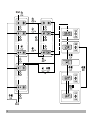
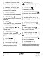
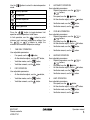
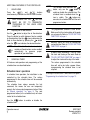
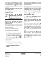
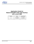
2. Name and function of switches and
icons (Refer to figure 1)
1
ON/OFF BUTTON
Press the ON/OFF button to start or stop the system.
2
OPERATION LAMP
The operation lamp lights up during operation or
blinks if a malfunction occurs.
3
OPERATION MODE ICON
These icons indicate the current operation mode
(FAN, DRY, AUTOMATIC, COOLING, HEATING).
4
VENTILATION MODE ICON
These icons indicate the current ventilation mode
(
only) (AUTOMATIC, HEAT EXCHANGE,
BYPASS).
5
VENTILATION ICON
The ventilation icon appears when the ventilation is
adjusted with the ventilation amount button (
only). Simultaneously, the ventilation amount is
indicated by the fan speed icon (see 22).
BRC1D527
Remote controller
4PW16770-1
6
AIR CLEANING ICON
This icon indicates that the air cleaning unit (option) is
operational.
7
LEAVE HOME ICON
The leave home icon shows the status of the leave
home function.
ON
Leave home is enabled
FLASHING
Leave home is active
OFF
Leave home is disabled
8
EXTERNAL CONTROL ICON
This icon indicates that another controller with higher
priority is controlling or disabling your installation.
9
CHANGE-OVER UNDER CENTRALISED
CONTROL ICON
This icon indicates that the change-over of the
installation is under centralised control assigned to
another indoor unit or optional cool/heat selector
connected to the outdoor unit (= master remote
controller).
10
DAY OF THE WEEK INDICATOR
The day of the week indicator shows the current week
day (or the set day when reading or programming the
schedule timer).
11
CLOCK DISPLAY
The clock display indicates the current time (or the
action time when reading or programming the
schedule timer).
Operation manual
2
12
MAXIMUM SET TEMPERATURE
The maximum set temperature indicates the
maximum set temperature when in limit operation.
21
13
MINIMUM SET TEMPERATURE
The minimum set temperature indicates the minimum
set temperature when in limit operation.
22
14
SCHEDULE TIMER ICON
This icon indicates that the schedule timer is enabled.
15
ACTION ICONS
These icons indicate the actions for each day of the
schedule timer.
16
OFF ICON
This icon indicates that the OFF action is selected
when programming the schedule timer.
NOT AVAILABLE
is displayed whenever a non-installed option
is addressed or a function is not available.
FAN SPEED ICON
This icon indicates the set fan speed.
23
DEFROST/HOTSTART MODE ICON
This icon indicates that the defrost/hotstart mode is
active.
24
AIR FILTER CLEANING TIME ICON
This icon indicates the air filter must be cleaned.
Refer to the manual of the indoor unit.
25
ELEMENT CLEANING TIME ICON
This icon indicates the element must be cleaned
(
only).
17
INSPECTION REQUIRED
and
These icons indicate that inspection is required.
Consult your installer.
26
VENTILATION MODE BUTTON
The ventilation mode button operates the
to the
manual for more details.
18
SET TEMPERATURE DISPLAY
This indicates the current set temperature of the
installation (not shown in LIMIT operation or in FAN or
DRY mode).
27
19
SETTING
Not used, for service purposes only.
20
AIR FLOW DIRECTION ICON
This icon indicates the air flow direction (only for
installations with motorised air flow flaps).
Operation manual
3
; refer
VENTILATION AMOUNT BUTTON
This button sets the ventilation amount; refer to the
manual for more details.
28
INSPECTION/TEST OPERATION BUTTON
Not used, for service purposes only.
29
PROGRAMMING BUTTON
This button is a multi-purpose button.
Depending on the previous manipulations of the user,
the programming button can have various functions.
BRC1D527
Remote controller
4PW16770-1
30
SCHEDULE TIMER BUTTON
This button enables or disables the schedule timer.
31
TIME ADJUST BUTTON
These buttons are used to adjust the clock or, when in
programming mode, to adjust the programmed action
time. Both buttons have an auto-repeat function.
32
TEMPERATURE ADJUST BUTTONS
These buttons are used to adjust the current setpoint
or, when in programming mode, to adjust the
programmed setpoint temperature (step = 1°C). Both
buttons are also used to adjust the day of the week.
33
OPERATION CHANGE/
BUTTON
This button is a multi-purpose button. Depending on
the previous manipulations of the user, it can have
following functions:
1 select the operation mode of the installation
(FAN, DRY, AUTOMATIC, COOLING, HEATING)
2 toggle between minimum temperature and
maximum temperature when in limit operation
34
SETPOINT/LIMIT BUTTON
This button toggles between setpoint, limit operation
or
(programming mode only).
35
FAN SPEED BUTTON
This button toggles between L (Low), H (High), HH
(very High),
(Automatic).
36
AIR FLOW DIRECTION ADJUST BUTTON
This button enables to adjust the air flow direction.
BRC1D527
Remote controller
4PW16770-1
37
AIR FILTER CLEANING TIME ICON RESET
BUTTON
This button is used to reset the air filter cleaning time
icon.
3. Setting up the controller
After initial installation, the user can set the clock and
day of the week.
The controller is equipped with a schedule timer that
enables the user to operate the installation
automatically; setting the clock and day of the week is
required to be able to use the schedule timer.
1
CLOCK SETTING FUNCTION
Hold down the
button for 5 seconds. The clock
read-out and the day of week indicator will blink, both
can now be adjusted.
Use the
&
buttons to adjust the
clock. Each time pressing the time adjust button will
in/decrease the time by 1 minute. Keeping the
or
button pressed will in/decrease
the time by 10 minutes.
Use the
&
buttons to adjust the day
of the week. Each time pressing the
or
buttons will display the next or previous day.
Press the
button to confirm the current set time
and day of the week.
If the controller, with blinking clock and day of week
read-out, is left untouched for 5 minutes, the clock
and day of the week will return to their previous
settings; the clock setting function is no longer active.
2
SETTING UP THE SCHEDULE TIMER
To set up the schedule timer, refer to chapter 6.
"Programming the schedule timer" on page 10.
Operation manual
4
4. Description of the operation modes
1
FAN ONLY OPERATION
In this mode, air only circulates without heating or
cooling.
2
DRY OPERATION
In this mode, the air humidity will be lowered with a
minimal temperature decrease.
The temperature and fan speed are controlled
automatically and cannot be controlled by the remote
controller.
Dry operation will not function if the room temperature
is too low.
3
AUTOMATIC OPERATION
In this mode, the controller will automatically switch
between heating and cooling as required by the
setpoint or limit temperature.
4
COOLING OPERATION
In this mode, cooling will be activated as required by
the setpoint or limit temperature.
5
HEATING OPERATION
In this mode, heating will be activated as required by
the setpoint or limit temperature.
Hot start (heat pump types only)
At the start of a heating operation, the indoor fan is
stopped until a certain indoor heat exchanger
temperature is reached and
is displayed.
This prevents cold air from leaving the indoor unit.
Operation manual
5
Defrost (heat pump types only)
In heating operation, freezing of the outdoor heat
exchanger may occur. If so, the heating capacity of
the system lowers and the system goes into defrost
operation. The indoor unit fan stops and
is
displayed. After maximum 10 minutes of defrost
operation, the system returns to heating operation
again.
6
LIMIT OPERATION
&
Limit operation is an additional mode that enables to
keep the room temperature within certain limits. The
&
icons are displayed to confirm the
activation of the limit operation.
7
LEAVE HOME
LEAVE HOME is a feature that enables to keep the
room temperature above 10°C when the occupants
are out. This function will switch on heating if the
installation is switched off.
5. Operation
Manual operation
In manual operation, the user decides about the
settings of the installation. The last setting remains
active until the user changes it.
As the controller can be implemented for a wide
variety of installations and features, it might occur that
you select a function that is not available on your
installation; if this is the case, the
message
will appear.
BRC1D527
Remote controller
4PW16770-1
Use the
mode.
button to select the desired operation
Fan only operation
Dry operation
&
•
Fan speed, use the
Automatic operation
•
Air flow direction adjust, use the
Cooling operation
•
Ventilation mode, use the
button,
Heating operation
•
Ventilation amount, use the
button.
Press the
button to toggle between limit
operation and the operations listed above.
In limit operation, use the
button to select
minimum and maximum temperature settings. Use
the
or
buttons to adjust the
minimum and maximum temperature settings.
1
FAN ONLY OPERATION
User adjustable parameters:
•
Fan speed, use the
button,
•
Air flow direction adjust, use the
button,
•
Ventilation mode, use the
button,
•
3
AUTOMATIC OPERATION
User adjustable parameters:
•
Setpoint temperature, use the
buttons,
Ventilation amount, use the
button.
2
DRY OPERATION
User adjustable parameters:
•
Air flow direction adjust, use the
•
Ventilation mode, use the
button,
button,
•
Ventilation amount, use the
button.
button,
4
COOLING OPERATION
User adjustable parameters:
•
Setpoint temperature, use the
buttons,
•
Fan speed, use the
button,
•
Air flow direction adjust, use the
&
button,
•
Ventilation mode, use the
button,
•
Ventilation amount, use the
button.
5
HEATING OPERATION
User adjustable parameters:
•
Setpoint temperature, use the
&
buttons,
•
Fan speed, use the
button,
•
Air flow direction adjust, use the
button,
•
Ventilation mode, use the
button,
•
Ventilation amount, use the
button.
6
LIMIT OPERATION
User adjustable parameters:
•
Fan speed, use the
button,
•
Air flow direction adjust, use the
button,
•
Ventilation mode, use the
button,
•
BRC1D527
Remote controller
4PW16770-1
button,
Ventilation amount, use the
button.
Operation manual
6
ADDITIONAL FEATURES OF THE CONTROLLER
1
LEAVE HOME
Press the
and
buttons
simultaneously to enable the LEAVE HOME function.
KEEP IN MIND THAT THE
BUTTON
MUST
BE
OFF TO
GUARANTEE
TRIGGERING OF THE LEAVE HOME
FUNCTION.
2
Adjusting the air flow direction
Use the
button to adjust the air flow direction.
Press the button to switch between fixed or variable
air flow direction. Use the
icon to determine the
fixed air flow direction by pressing the
button
when the
icon indicates the desired direction.
NOTE
Even if fixed air flow direction is selected,
variable air flow direction can be enabled
automatically
to
preserve
proper
operation of your installation.
3
SCHEDULE TIMER
All features and operation and programming of the
schedule timer are described below.
Schedule timer operation
In schedule timer operation, the installation is also
controlled by the schedule timer. The actions
programmed in the schedule timer will be executed
automatically.
The schedule timer always executes the last
command; this means the user can temporarily
overrule the last executed programmed action. Refer
to "Manual operation" on page 5. The next
programmed action (in the schedule timer) will return
control to the schedule timer.
Use the
schedule timer.
Operation manual
7
NOTE
The schedule timer overrules the
button, only use the
button to
enable or disable the schedule timer. The
schedule timer is enabled when the
icon is visible. The
button only
overrules the schedule timer until the next
programmed action.
The programmed schedule is time driven.
Make sure that the clock and day of the week
are set correctly. Refer to "CLOCK SETTING
FUNCTION" on page 4.
Manually adjust the clock for summertime
and wintertime. Refer to "CLOCK SETTING
FUNCTION" on page 4.
A power failure exceeding 1 hour will reset
the clock and the day of the week. Refer to
"CLOCK SETTING FUNCTION" on page 4
to adjust the clock and the day of the week.
The actions programmed in the schedule
timer will not be lost after a power failure;
reprogramming the schedule timer is not
required.
To set up the SCHEDULE TIMER refer to chapter 6.
"Programming the schedule timer" on page 10.
button to enable or disable the
BRC1D527
Remote controller
4PW16770-1
What can the schedule timer do?
The concept of the schedule timer is simple,
straightforward though powerful.
OR
•
The schedule timer can order 3 actions:
1 switch on the installation at a scheduled time, in
combination with a setpoint (exact temperature
control)
2 switch off the installation (end of control)
3 switch on the installation at a scheduled time, in
limit operation
The schedule timer can accept a maximum of 5
actions per day.
For each day of the week a maximum of 5 actions can
be programmed, totalling a maximum of 35
programmed actions. The action that was
programmed first for a certain day is action 1, the last
programmed action for a day could be action 1 (in
case only one action is programmed for that day) to 5.
It is of utmost importance to understand that
the number assigned to the programmed
action, DOES NOT DETERMINE WHEN the
programmed action will be executed. Only
the TIME, being a part of the data entered
when programming the action, will determine
when the programmed action will be
executed.
What will the schedule timer do?
If enabled, the schedule timer will execute the
programmed actions.
It will order the installation to:
•
cool or heat, depending on the current
operation, if applicable; the setpoint will be
displayed,
BRC1D527
Remote controller
4PW16770-1
OR
•
switch off the installation (the schedule timer
remains enabled and reactivates the
installation as programmed); the operation
lamp will turn off,
cool or heat, whichever is required to keep the
room temperature within a specified range
(limit operation);
and
are displayed.
The schedule timer will change the operation
mode in LIMIT operation only.
To be able to verify the programmed actions, you can
browse the programmed actions, see below.
What will the schedule timer NOT do?
The schedule timer will not:
•
control fan speed,
•
control air flow direction,
•
control ventilation mode,
•
control ventilation amount,
•
change the operation mode for a scheduled
setpoint.
The parameters listed above can be set manually,
without interfering with the schedule timer.
More sophisticated remote controllers are available.
Consult your dealer for more information.
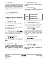
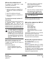
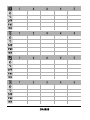
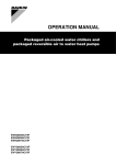
Browsing the programmed actions in
the schedule timer (read-out only)
Refer to figure 2.
Browsing the programmed actions of the schedule
timer is a sequential process. Only 2 buttons are used
to browse the entire schedule timer program.
The
button is used to start browsing, to display
the next programmed action or to exit browsing when
displaying the last programmed action.
Operation manual
8
The
button is used to exit browsing at once
(without having to scroll through all programmed
actions).
Press the
button to enter the browse mode, the
icon appears,
will blink.
NOTE
The temperatures mentioned above are
for clarifying purposes only, temperature
values on your controller may vary.
If
does not appear, it indicates that there are no
programmed actions for Monday.
Press the
button again to go to the next day of
the week.
will blink, this indicates that the
programmed actions for Tuesday are being browsed.
The process described above is now restarted.
If at least 1 action is programmed for Tuesday, will
appear. The clock indicates the time when the
programmed action will be enabled, either
,
or
and
is being displayed.
If
does not appear, it indicates that there are no
programmed actions for Tuesday.
Press the
button to display the next programmed
action. If a second action is programmed for Tuesday,
will still be blinking and
will appear.
Assuming that 5 actions were programmed for
Tuesday, a total of 5 presses will be required to
display all programmed actions.
Operation manual
9
NOTE
Browsing always starts on Monday and
ends on Sunday.
Check the
icon. If at least 1 action is
programmed for Monday, will appear.
The clock indicates the time when the programmed
action is scheduled, either
,
or
and
is being displayed.
NOTE
Continue pressing the
button until the day of the
week indicator displays the current day (not blinking),
you have now quit browsing.
The number of times that the
button
will have to be pressed to quit browsing
depends on the number of programmed
actions in the schedule timer.
How do I interpret the programmed
actions
To be able to understand the behaviour of your
installation when the schedule timer is enabled, it is
important to look at all programmed actions for the
current day and maybe the last programmed action of
yesterday.
If the first programmed action for today is not active
yet, the current status of your installation depends,
most probably but not necessarily, on the last
programmed action from yesterday. Read the
important note below.
If the first programmed action for today is already
active, the current status of your installation depends,
most probably but not necessarily, on the parameters
programmed in the first programmed action for today.
Read the important note below.
NOTE
To keep the operation of your installation
simple, the schedule timer settings can
easily be overruled by altering the current
setting ("last command" overrules
previous command until next scheduled
command).
Conclusion: Although
is displayed, somebody
might have altered the settings. The next
programmed action will overrule the altered settings
and all settings return as programmed.
BRC1D527
Remote controller
4PW16770-1
Programmed actions might overlap; due to the "last
command overrules" logic, the last scheduled
command will rule.
How do I interpret the readings on the
display when the schedule timer is
active
As described above, the schedule timer settings, (and
as a consequence the display readings) might be
overruled temporarily by a manual intervention.
If you want to be absolutely sure about the schedule
timer settings for this very moment, you must browse
the schedule timer programmed actions. Refer to
"Browsing the programmed actions in the schedule
timer" on page 8.
6. Programming the schedule timer
Getting started
Programming the schedule timer is flexible (you can
add, remove or alter programmed actions whenever
required) and straightforward (programming steps are
limited to a minimum).
Below are some tips and tricks to ensure successful
programming of the schedule timer:
•
•
•
•
•
What do I have to program?
As the schedule timer is based on a week program
(the same actions will be repeated every week) you
will have to select the day of the week first.
Now you must choose an action:
1 switch on the installation at a scheduled time, in
combination with a setpoint (exact temperature
control)
2
•
familiarise yourself with the icons and the
buttons, you will need them when
programming,
familiarise yourself with the browse function,
you will need it to start programming. Refer to
"Browsing the programmed actions in the
schedule timer" on page 8,
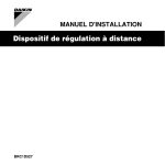
fill out the form at the end of this manual; note
the time and the required action for each day
(keep in mind that the number of actions is
limited to 5 per day),
take your time to enter all data accurately,
try to program the actions for each day in
logical sequence (start with action 1 for the
first action and end with the highest number for
the last action). This is not a requirement but it
will make it much easier to interpret the
program later,
keep in mind that you can always alter, add or
remove the programmed actions later.
switch off the installation (end of control)
3 switch on the installation at a scheduled time, in
limit operation
Finally you must enter the time of the day when the
action must be enabled.
NOTE
If you program 2 or more actions on the
same day and at the same time of the
day, only the action with the highest
action number (2 - 5) will be executed.
BRC1D527
Remote controller
4PW16770-1
Operation manual
10
Programming
1
THE SCHEDULE TIMER IS PROGRAMMED
FOR THE FIRST TIME
NOTE
When changing day during programming
you will have to confirm "the last action".
Each day can have 5 programmed
actions (numbered 1 to 5) but for some
reason you might want to delete one,
several or all programmed actions.
To be able to delete programmed actions,
you must select the last action that you
want to keep, this can be 1 to 5 or no
action (
is displayed and no action
displayed).
All programmed actions with a number
HIGHER than the selected one, or all
programmed actions if no last action was
selected will be deleted.
PROGRAMMING THE FIRST DAY OF THE WEEK
NOTE
In the guidelines below it is assumed that
you start programming the schedule
timer actions on Monday and end with the
schedule timer actions for Sunday.
If you prefer NOT to start on Monday, first
browse to the desired day and then enter
the PROGRAM mode.
Operation manual
11
In this particular case, no actions have been programmed before, all schedule timer actions are idle.
•
Browse to Monday by pressing the
button.
The
icon appears,
will blink and one of
the
icons might be displayed
but all other fields remain blank, indicating that
no actions are programmed for Monday.
•
Enter the program mode by holding down the
button for 5 seconds, the
icon will now
blink too.
•
Press the
button to activate the first
programmed action.
•
A blinking is displayed indicating that the first
programmed action for Monday is being
programmed; The set temperature and clock
display are blinking.
•
Press the
•
temperature,
, or limit operation.
Enter the desired temperature using the
&
buttons.
•
•
button to select either set
Press the
button to toggle between
minimum set temperature and maximum set
temperature in limit operation, the selected
temperature will blink.
Enter the time when the action must start
using the
&
buttons (min.
step = 10 minutes).
NOTE
If, by accident, you pressed the
button, you activated the next action;
is displayed ( steady and
blinking).
Press the
button repeatedly until a
blinking
is displayed. You can now
continue adjusting the settings for the first
schedule timer action.
BRC1D527
Remote controller
4PW16770-1
If the action and the corresponding time are correct,
you can proceed to the second schedule timer action.
This is done by pressing the
button, the data is
saved and the next schedule timer action can be
programmed.
Programming the remaining schedule timer actions
for the same day is similar.
You can browse the schedule timer actions by
pressing the
button.
NOTE
Don't worry if you add additional
schedule timer actions by pressing the
button repeatedly, they can be
deleted when finishing the current day.
When all data for the schedule timer actions for
Monday are entered, you must confirm the
programmed actions.
Make sure the last schedule timer action you want to
keep is selected (schedule timer actions with a higher
number will be deleted).
Now you must choose between 2 options:
1 CONFIRM AND COPY TO NEXT DAY
The schedule timer action programmed for the
current day are also valid for the next day: use
the "confirm last action and copy actions to next
day" function by pressing the
and
buttons simultaneously for 5 seconds.
Program mode is quit and depending on the choice
made, the programmed actions are saved for Monday
(and possibly Tuesday).
PROGRAMMING THE OTHER DAYS OF THE WEEK
Programming the other days of the week is identical
to programming the first day of the week.
is
blinking to indicate the selected day,
and
are
steady if actions were copied from Monday to
Tuesday, only
is displayed if no actions were
copied from Monday to Tuesday.
2
I WANT TO EDIT PROGRAMMED ACTIONS
Editing programmed actions is easy.
Make sure you are not in program mode (
not
blinking); if required, press the
button to quit
program mode.
Browse to the programmed actions using the
button, select the day and action you want to edit.
Press the
button for 5 seconds; program mode is
enabled, the
icon and selected action are blinking.
Edit the settings using the same buttons described
above.
Select the "last action" using the
button and
decide if you do or do not want to copy the
programmed action(s) to the next day (pressing the
and
buttons simultaneously or only the
button for 5 seconds).
2 CONFIRM ONLY
The schedule timer action programmed for the
current day are only valid for the selected day:
use the "confirm last action and go to next day"
function by pressing the
button for 5
seconds.
BRC1D527
Remote controller
4PW16770-1
Operation manual
12
3
I WANT TO DELETE ONE OR MORE
PROGRAMMED ACTIONS
Make sure you are not in program mode (
not
blinking); if required, press
to quit program
mode.
Browse to the programmed actions using the
button, select the day you want to edit.
Press the
button for 5 seconds; program mode is
enabled, the
icon and selected action are blinking.
Select the "last action" you want to keep using the
button. All higher actions will be deleted.
Confirm the deletion by pressing the
button for 5
seconds,
OR
confirm the deletion for the current and the next day
too by pressing the
and
buttons
simultaneously for 5 seconds.
NOTE
In the case above, if for example the last
action was 3, the programmed actions 4
and 5 will also be deleted (if they were
present).
4
I WANT TO DELETE ALL PROGRAMMED
ACTIONS AT ONCE
Quit programming or browsing.
Press the
and
buttons simultaneously for 5
seconds; the
icon will invert and disappear to
confirm deletion.
7. Maintenance
The remote controller does not need maintenance.
Remove dirt with a soft damp cloth.
NOTE
The guidelines below might help to solve your
problem. If you cannot remedy the problem, consult
your installer.
No readings on the remote controller (display
blank)
Check if the mains power is still applied to your
installation.
Only
is displayed
This indicates that the installation has just been
powered, please wait until
disappears.
The schedule timer does work but the
programmed actions are executed at the wrong
time (e.g. 1 hour too late or too early)
Check if the clock and the day of the week are set
correctly, correct if necessary (refer to "CLOCK
SETTING FUNCTION" on page 4).
I cannot enable the schedule timer (the
icon
blinks for 2 seconds and disappears)
The schedule timer has not been programmed yet.
First program the schedule timer (refer to
"Programming the schedule timer" on page 10).
I cannot enable the schedule timer (the
icon is displayed)
The schedule timer can not be enabled when a
centralised control is connected.
Limit operation cannot be selected
Limit operation is not available for cooling only
installations.
Only use clear tapid water to moisten the
cloth.
Operation manual
13
8. Troubleshooting
BRC1D527
Remote controller
4PW16770-1
NOTES
Zandvoordestraat 300, B-8400 Oostende, Belgium
4PWEN16770-1