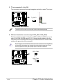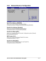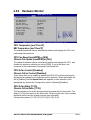
1
User Guide
Motherboard
P4R800-VM
E1511
Checklist
Revised Edition V3
December 2003
Copyright © 2003 ASUSTeK COMPUTER INC. All Rights Reserved.
No part of this manual, including the products and software described in it, may be
reproduced, transmitted, transcribed, stored in a retrieval system, or translated into any
language in any form or by any means, except documentation kept by the purchaser for
backup purposes, without the express written permission of ASUSTeK COMPUTER INC.
(“ASUS”).
Product warranty or service will not be extended if: (1) the product is repaired, modified or
altered, unless such repair, modification of alteration is authorized in writing by ASUS; or (2)
the serial number of the product is defaced or missing.
ASUS PROVIDES THIS MANUAL “AS IS” WITHOUT WARRANTY OF ANY KIND, EITHER
EXPRESS OR IMPLIED, INCLUDING BUT NOT LIMITED TO THE IMPLIED WARRANTIES
OR CONDITIONS OF MERCHANTABILITY OR FITNESS FOR A PARTICULAR PURPOSE.
IN NO EVENT SHALL ASUS, ITS DIRECTORS, OFFICERS, EMPLOYEES OR AGENTS BE
LIABLE FOR ANY INDIRECT, SPECIAL, INCIDENTAL, OR CONSEQUENTIAL DAMAGES
(INCLUDING DAMAGES FOR LOSS OF PROFITS, LOSS OF BUSINESS, LOSS OF USE
OR DATA, INTERRUPTION OF BUSINESS AND THE LIKE), EVEN IF ASUS HAS BEEN
ADVISED OF THE POSSIBILITY OF SUCH DAMAGES ARISING FROM ANY DEFECT OR
ERROR IN THIS MANUAL OR PRODUCT.
SPECIFICATIONS AND INFORMATION CONTAINED IN THIS MANUAL ARE FURNISHED
FOR INFORMATIONAL USE ONLY, AND ARE SUBJECT TO CHANGE AT ANY TIME
WITHOUT NOTICE, AND SHOULD NOT BE CONSTRUED AS A COMMITMENT BY ASUS.
ASUS ASSUMES NO RESPONSIBILITY OR LIABILITY FOR ANY ERRORS OR
INACCURACIES THAT MAY APPEAR IN THIS MANUAL, INCLUDING THE PRODUCTS
AND SOFTWARE DESCRIBED IN IT.
Products and corporate names appearing in this manual may or may not be registered
trademarks or copyrights of their respective companies, and are used only for identification or
explanation and to the owners’ benefit, without intent to infringe.
ii
Contents
Features
Notices ........................................................................................... vi
Safety information ......................................................................... vii
About this guide ............................................................................ viii
P4R800-VM specification summary ............................................... ix
Chapter 1: Product introduction
1.1
Welcome! ........................................................................... 1-2
1.2
Package contents ............................................................... 1-2
1.3
Special features .................................................................. 1-2
1.4
Before you proceed ............................................................ 1-5
1.5
Motherboard overview ........................................................ 1-6
1.5.1 Motherboard layout ................................................ 1-6
1.5.2 Placement direction ............................................... 1-7
1.5.3 Screw holes ........................................................... 1-7
Central Processing Unit (CPU) ........................................... 1-8
1.6.1 Overview ................................................................ 1-8
1.6.2 Installing the CPU .................................................. 1-9
System memory ............................................................... 1-10
1.7.1 DIMM sockets location ......................................... 1-10
1.7.2 Memory configurations ........................................ 1-10
1.7.3 Installing a DIMM ................................................. 1-12
Expansion slots ................................................................ 1-12
1.8.1 Standard interrupt assignments ........................... 1-13
1.8.2 IRQ assignments for this motherboard ................ 1-13
1.8.3 PCI slots .............................................................. 1-14
1.8.4 AGP slot ............................................................... 1-14
Jumpers ............................................................................ 1-15
1.6
1.7
1.8
1.9
1.10 Connectors ....................................................................... 1-17
1.10.1 Rear panel connectors ......................................... 1-17
1.10.2 Internal connectors .............................................. 1-18
iii
Contents
Safeguards
Chapter 2: BIOS information
2.1
2.2
2.3
2.4
2.5
iv
Managing and updating your BIOS .................................... 2-2
2.1.1 Creating a bootable floppy disk ............................. 2-2
2.1.2 Using AFUDOS to copy the current BIOS ............. 2-3
2.1.3 Using AFUDOS to update the BIOS ...................... 2-3
2.1.4 Using ASUS EZ Flash to update the BIOS ............ 2-5
2.1.5 Recovering the BIOS with CrashFree BIOS 2 ....... 2-6
BIOS Setup program .......................................................... 2-8
2.2.1 BIOS menu screen ................................................ 2-9
2.2.2 Menu bar ................................................................ 2-9
2.2.3 Navigation keys ..................................................... 2-9
2.2.4 Menu items .......................................................... 2-10
2.2.5 Sub-menu items ................................................... 2-10
2.2.6 Configuration fields .............................................. 2-10
2.2.7 Pop-up window .................................................... 2-10
2.2.8 Scroll bar .............................................................. 2-10
2.2.9 General help ........................................................ 2-10
Main menu .........................................................................2-11
2.3.1 System Time .........................................................2-11
2.3.2 System Date .........................................................2-11
2.3.3 Legacy Diskette A .................................................2-11
2.3.4 Primary/Secondary IDE Master/Slave ................. 2-12
2.3.5 System Information .............................................. 2-13
Advanced menu ............................................................... 2-14
2.4.1 CPU Configuration ............................................... 2-14
2.4.2 Chipset ................................................................. 2-15
2.4.3 Onboard Devices Configuration ........................... 2-17
2.4.4 PCI PnP ............................................................... 2-18
Power menu ..................................................................... 2-19
2.5.1 Suspend Mode ..................................................... 2-19
2.5.2 Repost Video on S3 Resume ............................... 2-19
2.5.3 ACPI 2.0 Support ................................................. 2-19
2.5.4 ACPI APIC Support .............................................. 2-19
2.5.5 APM Configuration ............................................... 2-20
2.5.6 Hardware Monitor ................................................ 2-21
Contents
2.6
2.7
Boot menu ........................................................................ 2-22
2.6.1 Boot Device Priority ............................................. 2-22
2.6.2 Boot Settings Configuration ................................. 2-23
2.6.3 Security ................................................................ 2-24
Exit menu ......................................................................... 2-26
Chapter 3: Software support
3.1
Install an operating system ................................................. 3-2
3.2
Support CD information ...................................................... 3-2
3.2.1 Running the support CD ........................................ 3-2
3.2.2 Drivers menu ......................................................... 3-3
3.2.3 Utilities menu ......................................................... 3-3
3.2.4 ASUS Contact Information ..................................... 3-4
v
Notices
Federal Communications Commission Statement
This device complies with FCC Rules Part 15. Operation is subject to the
following two conditions:
• This device may not cause harmful interference, and
• This device must accept any interference received including interference
that may cause undesired operation.
This equipment has been tested and found to comply with the limits for a
Class B digital device, pursuant to Part 15 of the FCC Rules. These limits
are designed to provide reasonable protection against harmful interference
in a residential installation. This equipment generates, uses and can radiate
radio frequency energy and, if not installed and used in accordance with
manufacturer’s instructions, may cause harmful interference to radio
communications. However, there is no guarantee that interference will not
occur in a particular installation. If this equipment does cause harmful
interference to radio or television reception, which can be determined by
turning the equipment off and on, the user is encouraged to try to correct the
interference by one or more of the following measures:
• Reorient or relocate the receiving antenna.
• Increase the separation between the equipment and receiver.
• Connect the equipment to an outlet on a circuit different from that to
which the receiver is connected.
• Consult the dealer or an experienced radio/TV technician for help.
The use of shielded cables for connection of the monitor to the
graphics card is required to assure compliance with FCC regulations.
Changes or modifications to this unit not expressly approved by the
party responsible for compliance could void the user’s authority to
operate this equipment.
Canadian Department of Communications Statement
This digital apparatus does not exceed the Class B limits for radio noise
emissions from digital apparatus set out in the Radio Interference
Regulations of the Canadian Department of Communications.
This class B digital apparatus complies with Canadian ICES-003.
vi
Safety information
Electrical safety
• To prevent electrical shock hazard, disconnect the power cable from
the electrical outlet before relocating the system.
• When adding or removing devices to or from the system, ensure that
the power cables for the devices are unplugged before the signal
cables are connected. If possible, disconnect all power cables from the
existing system before you add a device.
• Before connecting or removing signal cables from the motherboard,
ensure that all power cables are unplugged.
• Seek professional assistance before using an adpater or extension
cord. These devices could interrupt the grounding circuit.
• Make sure that your power supply is set to the correct voltage in your
area. If you are not sure about the voltage of the electrical outlet you
are using, contact your local power company.
• If the power supply is broken, do not try to fix it by yourself. Contact a
qualified service technician or your retailer.
Operation safety
• Before installing the motherboard and adding devices on it, carefully
read all the manuals that came with the package.
• Before using the product, make sure all cables are correctly connected
and the power cables are not damaged. If you detect any damage,
contact your dealer immediately.
• To avoid short circuits, keep paper clips, screws, and staples away from
connectors, slots, sockets and circuitry.
• Avoid dust, humidity, and temperature extremes. Do not place the
product in any area where it may become wet.
• Place the product on a stable surface.
• If you encounter technical problems with the product, contact a
qualified service technician or your retailer.
vii
About this guide
Conventions used in this guide
To make sure that you perform certain tasks properly, take note of the
following symbols used throughout this guide.
WARNING: Information to prevent injury to yourself when trying
to complete a task.
CAUTION: Information to prevent damage to the components
when trying to complete a task.
IMPORTANT: Information that you MUST follow to complete a
task.
NOTE: Tips and additional information to aid in completing a task.
Where to find more information
Refer to the following sources for additional information and for product
and software updates.
1. ASUS websites
The ASUS websites worldwide provide updated information on ASUS
hardware and software products. Refer to the ASUS contact
information.
2. Optional documentation
Your product package may include optional documentation, such as
warranty flyers, that may have been added by your dealer. These
documents are not part of the standard package.
viii
P4R800-VM specification summary*
CPU
Socket 478 for Intel® Pentium® 4 Northwood processor
Intel® Hyper-Threading technology ready
New power design for next generation Intel® Prescott CPU
Chipset
ATI RADEON™ 9100 IGP
ATI IXP200
Front Side Bus (FSB)
800/533/400 MHz
Memory
4 x 184-pin DDR DIMM sockets for up to 4GB memory
Supports PC3200*/2700/2100/1600 unbuffered non-ECC
DDR DIMMs. (*Supports one single-sided PC3200 [DDR400] DIMM
per channel only)
Expansion slots
1 x AGP 8X/4X (1.5V only)
3 x PCI
VGA
ATI Radeon™ 9200 integrated graphics
Storage
2 x UltraATA100/66, PIO Mode 0 ~ 4
Audio
ADI AD1888 6-channel audio CODEC
LAN
IXP200 built in 3Com MAC with Realtek 8201BL/CL LAN PHY
Hardware monitoring
Super I/O integrated monitoring of CPU/chassis fan rotation
and MB/CPU temperature
Special features
Digital audio via an S/PDIF out inteface
TV out support
ASUS MyLogo2
ASUS EZ Flash
ASUS Q-Fan Technology
ASUS CrashFree BIOS2
Rear panel I/O
1 x Parallel port
1 x VGA port
1 x S/PDIF port
1 x PS/2 keyboard port
1 x PS/2 mouse port
4 x USB 2.0/USB 1.1 ports
1 x RJ-45 port
Line In/Line Out/Microphone ports
(continued on the next page)
ix
P4R800-VM specification summary*
Internal I/O
1 x USB 2.0/1.1 connector for 2 additional USB ports
CPU and chassis fan connectors
20-pin/4-pin ATX 12V power connectors
CD/AUX audio connectors
Front panel audio connector
Panel connectors
COM connector
TV-out connector
Power LED connector**
BIOS features
4Mb Flash EEPROM, AMI BIOS with enhanced ACPI, DMI,
Green,PnP features, SM BIOS2.3, ASUS CrashFree BIOS2,
ASUS MyLogo2, and ASUS EZ Flash
Industry standard
PCI 2.2, USB 2.0/1.1
Manageability
WOL by PME, Wake on USB KB/Mouse
Form Factor
Micro-ATX form factor: 9.6 in x 9.6 in (24.5 cm x 24.5 cm)
Support CD contents
Device drivers
ASUS PC Probe
ASUS LiveUpdate
ASUS Screensaver
Adobe Acrobat Reader
Trend Micro™ PC-cillin 2002 anti-virus software
Microsoft® DirectX 8.1
* Specifications are subject to change without notice.
** Present only on PCB version 1.03 or later.
x
Chapter 1
This chapter describes the features of this
motherboard. It includes brief descriptions of the
motherboard components, and illustrations of the
layout, jumper settings, and connectors.
Product introduction
1.1
Welcome!
Thank you for buying the ASUS® P4R800-VM motherboard!
The ASUS P4R800-VM motherboard delivers a host of new features and latest
technologies making it another standout in the long line of ASUS quality
motherboards!
Before you start installing the motherboard, and hardware devices on it, check the
items in your package with the list below.
1.2
Package contents
Check your P4R800-VM package for the following items.
ASUS P4R800-VM motherboard
Micro-ATX form factor: 9.6 in x 9.6 in (24.5 cm x 24.5 cm)
ASUS P4R800-VM series support CD
Serial (COM) port module and cable
80-conductor UltraATA IDE cable
Ribbon cable for a 3.5-inch floppy drive
I/O shield
Bag of extra jumper caps
User Guide
If any of the above items is damaged or missing, contact your retailer.
1.3
Special features
Intel® 800MHz FSB CPU support
The P4R800-VM comes with a 478-pin surface mount, Zero Insertion Force (ZIF)
socket for the Intel® Pentium® 4 Northwood/Willamette processor in the 478-pin
package with 512/256KB L2 cache on 0.13 micron process. This motherboard
supports 800/533/400 MHz system front side bus that allows 6.4GB/s, 4.3GB/s and
3.2GB/s data transfer rates, respectively. The P4R800-VM also supports the Intel®
Hyper-Threading Technology and the next-generation Intel® Prescott CPU.
See page 1-8.
ATi RADEON 9100 IGP/IXP200 chipset
The embedded RADEON™ 9100 Integrated Graphics Processor (IGP) northbridge
and the IXP200 southbridge chipset control all interfaces to ensure an efficient and
reliable computing performance. See page 2-15 and 2-16.
1-2
Chapter 1: Product introduction
The RADEON™ 9100 IGP provides processor interface with 800/533/400 MHz
frequency, system memory interface at 400/333/266/200MHz operation, and 1.5V
AGP interface that supports AGP 8X specification.
The IXP 200 (SB200) is a subsystem that integrates various I/O functions including
dual-channel ATA100 bus master IDE controller, up to six USB 2.0/1.1 ports, I/O
APIC interrupt and Ethernet controllers, and LPC, AC’97 2.2 interfaces, Ethernet
controller, and PCI 2.2 interface. The proprietary A-Link interface connects the IXP
200 with the RADEON™ IGP at up to 266MB/s data transfer rate.
Dual channel DDR400 memory support
The P4R800-VM supports a single or dual memory architecture for up to 4GB
system memory. Four (4) 184-pin DIMM sockets are available for installation of
unbuffered non-ECC PC3200/2700/2100/1600 DDR DIMMs. See page 1-10.
ATi RADEON 9200-based GPU
Integrated in the IGP chipset is the ATI RADEON™ 9200-based 2D/3D graphics
engine with maximum 128MB shared display memory. The integrated graphics
also supports TV out function through a separate TV out module (AV/S). The
RADEON 9200-based GPU achieves a maximum resolution of 2048x1536 at
32bpp. See page 1-20.
Integrated 3Com 10/100 Mbps LAN MAC
The integrated 3Com MAC in the IXP 200 southbridge works with the onboard
Realtek 8201BL/CL LAN PHY to fully support 10BASE-T/ 100BASE-TX Ethernet
networking. See page 1-17.
SoundMAX digital audio system
The SoundMax Digital Audio System is the industry’s highest performance and
most reliable audio solution for business professionals, audiophiles, musicians,
and gamers. SoundMAX Digital Audio System can output 5.1 channel surround
and features state-of-the-art DLS2 MIDI synthesizer with Yamaha DLSbyXG sound
set, 5.1 Virtual Theater™ and supports all major game audio technologies
including Microsoft DirectX™8.0, Microsoft DirectSound 3D™, A3D, MacroFX,
ZoomFX, MultiDrive 5.1 and EAX. See page 1-17.
USB 2.0 connectivity
The P4R800-VM rear panel comes with four (4) Universal Serial Bus (USB) ports
to connect USB 2.0 devices. A USB header is also available at mid-board to
accommodate a USB module for two (2) additional USB ports. The USB ports and
header comply with USB 2.0 specification that supports up to 480 Mbps connection
speed. This speed advantage over the conventional USB 1.1 (12 Mbps) allows
faster Internet connection, interactive gaming, and simultaneous running of
high-speed peripherals. USB 2.0 is backward compatible with USB 1.1.
See pages 1-17 and 1-21.
ASUS P4R800-VM motherboard user guide
1-3
CrashFree BIOS2
This feature allows you to restore the original BIOS data from the support CD, or
from a bootable floppy disk, when the BIOS codes and data are corrupted. This
protection eliminates the need to buy a replacement ROM chip. See page 2-6.
ASUS Q-Fan technology
The ASUS Q-Fan technology smartly adjusts the fan speeds according to the
system loading to ensure quiet, cool, and efficient operation. See page 2-21.
ASUS EZ Flash BIOS
With the ASUS EZ Flash, you can easily update the system BIOS even before
loading the operating system. No need to use a DOS-based utility or boot from a
floppy disk. See page 2-5.
ASUS MyLogo2
This new feature present in the motherboard allows you to personalize and add
style to your system with customizable boot logos. The ASUS MyLogo2 is
automatically installed when you install the ASUS Update utility from Utilities menu
in the support CD. See page 3-3.
1-4
Chapter 1: Product introduction
1.4
Before you proceed
Take note of the following precautions before you install motherboard components
or change any motherboard settings.
1.
Unplug the power cord from the wall socket before touching any
component.
2.
Use a grounded wrist strap or touch a safely grounded object or to a metal
object, such as the power supply case, before handling components to
avoid damaging them due to static electricity.
3.
Hold components by the edges to avoid touching the ICs on them.
4.
Whenever you uninstall any component, place it on a grounded antistatic
pad or in the bag that came with the component.
5.
Before you install or remove any component, ensure that the ATX
power supply is switched off or the power cord is detached from the
power supply. Failure to do so may cause severe damage to the
motherboard, peripherals, and/or components.
Onboard LED
The P4R800-VM comes with a stand-by power LED. When lit, the green LED
indicates that the system is ON, in sleep mode, or in soft-off mode, a reminder that
you should shut down the system and unplug the power cable before removing or
plugging in any motherboard component. The illustration below shows the location
of the onboard LED.
P4R800-VM
SB_PWR1
P4R800-VM Onboard LED
ON
Standby
Power
ASUS P4R800-VM motherboard user guide
OFF
Powered
Off
1-5
1.5
Motherboard overview
1.5.1 Motherboard layout
24.5cm (9.6in)
KBPWR1
Socket 478
TV-OUT1
CHA_FAN1
ATI
RADEON
9100
IGP
2 3
+5V
(Default)
+5VSB
USBPW12
1 2
ATX Power Connector
ATX12V1
USB2.0
Top:
T: USB3 RJ-45
B: USB4
DDR DIMM_B2 (64 bit,184-pin module)
USBPW34
DDR DIMM_B1 (64 bit,184-pin module)
VGA1
DDR DIMM_A2 (64 bit,184-pin module)
PARALLEL PORT
DDR DIMM_A1 (64 bit,184-pin module)
CPU_FAN1
1 2
Top:Line In
Center:Line Out
Below:Mic In
P4R800-VM
Accelerated Graphics Port (AGP1)
24.5cm (9.6in)
USB1
USB2
SPDIF_O
Super
I/O
KBPWR1
USBPW12
FLOPPY1
PS/2KBMS
T: Mouse
B: Keyboard
2 3
+5V
(Default)
+5VSB
USBPW34
1 2
2 3
+5V
(Default)
+5VSB
SEC_IDE1
PCI1
FP_AUDIO1
CD1
ATI
IXP200
PCI2
PRI_IDE1
CLRTC1
AUX1
CR2032 3V
Lithium Cell
CMOS Power
PCI3
AD1888
CODEC
USB56
USBPW56
PLED1
1
4Mbit
Firmware
Hub
PLED+
NC
PLED-
RTL
8201BL
SB_PWR1
COM1
PLED1
SPEAK1 F_PANEL1
+5V
(Default)
CLRTC1
2 3
+5VSB
2
1
Normal
(Default)
3
2
F_PANEL1
Power LED
Power Switch
Power LED+
Power LEDPower Switch
Ground
USBPW56
1 2
Clear CMOS
IDE LED+
IDE LEDGround
Reset
F_PANEL1
IDE_LED
Reset Switch
* Requires an ATX power supply.
1-6
Chapter 1: Product introduction
1.5.2 Placement direction
When installing the motherboard, make sure that you place it into the chassis in
the correct orientation. The edge with external ports goes to the rear part of the
chassis as indicated in the image below.
1.5.3 Screw holes
Place eight (8) screws into the holes indicated by circles to secure the
motherboard to the chassis.
Do not overtighten the screws! Doing so may damage the motherboard.
Place this side towards
the rear of the chassis
ASUS P4R800-VM motherboard user guide
1-7
1.6
Central Processing Unit (CPU)
1.6.1 Overview
The Intel® Pentium® 4 processor has a gold triangular mark on one corner. This
mark indicates the processor Pin 1 that should match a specific corner of the CPU
socket.
Gold Arrow
P4R800-VM
P4R800-VM Socket 478
Incorrect installation of the CPU into the socket may bend the pins and
severely damage the CPU!
Notes on Intel® Hyper-Threading Technology
1-8
1.
Hyper-Threading Technology is supported under Windows® XP and Linux
2.4.x (kernel) and later versions only. Under Linux, use the Hyper-Threading
compliler to compile the code. If you are using any other operating systems,
disable the Hyper-Threading Techonology item in BIOS to ensure system
stability and performance.
2.
It is recommended that you install WinXP Service Pack 1.
3.
Make sure to enable the Hyper-Threading Technology item in BIOS before
installing a supported operating system.
4.
For more information on Hyper-Threading Technology, visit www.intel.com/
info/hyperthreading.
Chapter 1: Product introduction
1.6.2 Installing the CPU
Follow these steps to install a CPU.
1. Locate the 478-pin ZIF socket on the motherboard.
2. Unlock the socket by pressing the
lever sideways, then lift it up to a 90°100° angle.
Socket Lever
90 - 100
Make sure that the socket lever is
lifted up to 90°-100° angle,
otherwise the CPU does not fit in
completely.
3. Position the CPU above the socket
such that its marked corner matches
the base of the socket lever.
Gold Mark
4. Carefully insert the CPU into the
socket until it fits in place.
The CPU fits only in one correct
orientation. DO NOT force the
CPU into the socket to prevent
bending the pins and damaging
the CPU!
5. When the CPU is in place, push down
the socket lever to secure the CPU.
The lever clicks on the side tab to
indicate that it is locked.
6. Install a CPU heatsink and fan
following the instructions that came
with the heatsink package.
7. Connect the CPU fan cable to the
CPU_FAN1 connector on the
motherboard.
ASUS P4R800-VM motherboard user guide
1-9
1.7
System memory
1.7.1 DIMM sockets location
80 Pins
104 Pins
DIMM_B2
DIMM_A2
DIMM_B1
DIMM_A1
The following figure illustrates the location of the DDR DIMM sockets.
P4R800-VM
P4R800-VM 184-Pin DDR DIMM Sockets
Make sure to unplug the power supply before adding or removing DIMMs or
other system components. Failure to do so may cause severe damage to both
the motherboard and the components.
When installing long AGP cards, it is recommended to install the memory
modules first. Long AGP cards, when installed, may interfere with the memory
sockets.
1.7.2 Memory configurations
You may install 64MB, 128MB, 256MB, 512MB, and 1GB DDR DIMMs into the
DIMM sockets using the memory configurations in this section.
Important notes
1-10
1.
Installing DDR DIMMs other than the recommended configurations may
cause memory sizing error or system boot failure. Use any of the
recommended configurations in Table 1.
2.
A three-DIMM configuration is not supported on this motherboard
3.
In dual-channel configurations, always install an identical (the same type
and size) DDR DIMM pair on sockets of the same color.
3.
Always install DIMMs with the same CAS latency. For optimum
compatibility, it is recommended that you obtain memory modules from the
same vendor.
Chapter 1: Product introduction
Table 1: Recommended memory configurations
Mode/DIMM Type
DIMM_A1
(blue)
Sockets
DIMM_A2 DIMM_B1
(black)
(blue)
DIMM_B2
(black)
Single-channel
(1)
Populated
—
—
—
(PC3200/PC2700/
PC2100/PC1600)
(2)
—
Populated
—
—
(3)
—
—
Populated
—
(4)
—
—
—
Populated
Dual-channel
(1)
Populated
—
Populated
—
(PC2700/PC2100/
PC1600)
(2)
—
Populated
—
Populated
Dual-channel
(PC3200)
(3)*
Populated Populated Populated Populated
(1)
Populated
—
(Single-sided)
Populated
—
(Single-sided)
* For dual-channel configuration (3), you may:
• install identical DIMMs in all four sockets or
• install identical DIMM pair in DIMM_A1 and DIMM_B1 (blue sockets)
and identical DIMM pair in DIMM_A2 and DIMM_B2 (black sockets)
•
This motherboard supports one single-sided PC3200 (DDR400) DIMM per
channel only.
•
This motherboard may only detect PC2700 (DDR333) system memory
when you install two PC3200 (DDR400) DIMMs in one channel or when
you install double-sided PC3200 (DDR400) DIMMs.
Table 2: Qualified DDR400 vendors list
This table lists the memory modules that have been tested and qualified for use
with this motherboard.
Size
Vendor
Part Number
256MB
TwinMOS
256MB
HYNIX
HYMD232646A8J
256MB
Samsung
M368L3223DTM-CC4
256MB
Corsair
CM256A-3500C2PT
––
SS
––
256MB
Kingston
VALUERAM KVR400X64C25/256
Winbond
SS
W942508BH-5
256MB
Transcend
TS32MLD64V4F3
MOSEL
SS
V58C2256804SAT5
––
Chip Brand
Sides
Chip Number
Winbond
SS
W94508BH-5
HYNIX
SS
HY5DU56822AT-U43
Samsung
SS
K4H560838D TCC4
Legend: DS — Double-sided SS — Single-sided
Obtain DDR DIMMs only from ASUS qualified vendors. Visit the ASUS website
(www.asus.com) for the latest QVL.
ASUS P4R800-VM motherboard user guide
1-11
1.7.3 Installing a DIMM
Follow these steps to install a DIMM.
DDR DIMM notch
1. Unlock a DIMM socket by pressing
the retaining clips outward.
2. Align a DIMM on the socket such that
the notch on the DIMM matches the
break on the socket.
3. Firmly insert the DIMM into the socket
until the retaining clips snap back in
place and the DIMM is properly
seated.
Unlocked
Retaining Clip
A DDR DIMM is keyed with a notch so that it fits in only one direction. DO NOT
force a DIMM into a socket to avoid damaging the DIMM.
1.8
Expansion slots
To install and configure an expansion card:
1. Install an expansion card following the instructions that came with the chassis.
2. Turn on the system and change the necessary BIOS settings, if any. See
Chapter 2 for BIOS information.
3. Assign an IRQ to the card. Refer to the tables next page.
4. Install the drivers and/or software applications for the expansion card
according to the card documentation.
1-12
Chapter 1: Product introduction
1.8.1 Standard interrupt assignments
*
IRQ
Priority
Standard Function
0
1
System Timer
1
2
Keyboard Controller
2
N/A
Programmable Interrupt
3*
11
Communications Port (COM2)
4*
12
Communications Port (COM1)
5*
13
IRQ holder for PCI steering
6
14
Floppy Disk Controller
7*
15
Printer Port (LPT1)
8
3
System CMOS/Real Time Clock
9*
4
IRQ holder for PCI steering
10*
5
Advance AC’97 CODEC
11*
6
Standard PCI Graphics Adapter (VGA)
12*
7
PS/2 Compatible Mouse Port
13
8
Numeric Data Processor
14*
9
Primary IDE Channel
15*
10
Secondary IDE Channel
These IRQs are usually available for ISA or PCI devices.
1.8.2 IRQ assignments for this motherboard
PCI slot 1
PCI slot 2
PCI slot 3
AGP slot
Onboard USB controller 1
Onboard USB controller 2
Onboard USB controller 3
Onboard USB 2.0 controller
Onboard LAN
Onboard audio
A
—
—
shared
shared
—
—
—
—
—
—
B
—
—
—
—
—
—
—
—
—
used
C
shared
—
—
—
—
—
—
—
shared
—
D
—
shared
—
—
shared
shared
shared
shared
—
—
When using PCI cards on shared slots, ensure that the drivers support “Share
IRQ” or that the cards do not need IRQ assignments. Otherwise, conflicts will
arise between the two PCI groups, making the system unstable and the card
inoperable.
ASUS P4R800-VM motherboard user guide
1-13
1.8.3 PCI slots
The PCI slots support PCI cards such as a LAN card, SCSI card, USB card, and
other cards that comply with PCI specifications.
1.8.4 AGP slot
The Accelerated Graphics Port (AGP) slot that supports AGP 8X/4X (+1.5V) cards.
When you buy an AGP card, make sure that you ask for one with +1.5V
specification.
Note the notches on the card golden fingers to ensure that they fit the AGP slot on
the motherboard.
This motherboard does not support 3.3V AGP cards. Install only +1.5V AGP
cards.
P4R800-VM
Keyed for 1.5v
P4R800-VM Accelerated Graphics Port (AGP)
1-14
Chapter 1: Product introduction
1.9
Jumpers
1. Clear RTC RAM (CLRTC1)
This jumper allows you to clear the Real Time Clock (RTC) RAM in CMOS.
You can clear the CMOS memory of date, time, and system setup parameters
by erasing the CMOS RTC RAM data. The RAM data in CMOS, that include
system setup information such as system passwords, is powered by the
onboard button cell battery.
To erase the RTC RAM:
1. Turn OFF the computer and unplug the power cord.
2. Move the jumper cap from pins 1-2 (default) to pins 2-3. Keep the cap on
pins 2-3 for about 5~10 seconds, then move the cap back to pins 1-2.
3. Plug the power cord and turn ON the computer.
4. Hold down the <Del> key during the boot process and enter BIOS setup to
re-enter data.
Except when clearing the RTC RAM, never remove the cap on CLRTC1 jumper
default position. Removing the cap will cause system boot failure!
CLRTC1
P4R800-VM
2
1
Normal
(Default)
3
2
Clear CMOS
P4R800-VM Clear RTC RAM
ASUS P4R800-VM motherboard user guide
1-15
2. USB device wake-up (3-pin USBPW12, USBPW34, USBPW56)
Set these jumpers to +5V to wake up the computer from S1 sleep mode (CPU
stopped, DRAM refreshed, system running in low power mode) using the
connected USB devices. Set to +5VSB to wake up from S3 sleep mode (no
power to CPU, DRAM in slow refresh, power supply in reduced power mode).
Both jumpers are set to pins 1-2 (+5V) by default because not all computers
have the appropriate power supply to support this feature.
The USBPW_12 and USBPW_34 jumpers are for the rear USB ports. The
USBPW_56 jumper is for the internal USB header that you can connect to the
front USB ports.
1.
This feature requires a power supply that can provide at least 1A on the
+5VSB lead when these jumpers are set to +5VSB. Otherwise, the system
would not power up.
2.
The total current consumed must NOT exceed the power supply capability
(+5VSB) whether under normal condition or in sleep mode.
USBPW12
1 2
2 3
+5V
(Default)
+5VSB
USBPW34
1 2
2 3
P4R800-VM
+5V
(Default)
+5VSB
USBPW56
1 2
P4R800-VM USB Device Wake Up
2 3
+5V
(Default)
+5VSB
3. Keyboard power (3-pin KBPWR1)
This jumper allows you to enable or disable the keyboard wake-up feature. Set
this jumper to pins 2-3 (+5VSB) if you wish to wake up the computer when you
press a key on the keyboard (the default is the Space Bar). This feature
requires an ATX power supply that can supply at least 1A on the +5VSB lead,
and a corresponding setting in the BIOS (see 2.5.5 “APM Configuration”).
KBPWR1
1 2
P4R800-VM
2 3
+5V
(Default)
+5VSB
P4R800-VM Keyboard Power Setting
1-16
Chapter 1: Product introduction
1.10 Connectors
This section describes and illustrates the motherboard rear panel and internal
connectors.
1.10.1 Rear panel connectors
1
2
3
4
5
6
11
10
9
8
7
1. PS/2 mouse port. This green 6-pin connector is for a PS/2 mouse.
2. Parallel port. This 25-pin port connects a parallel printer, a scanner, or other
devices.
3. RJ-45 port. This port allows connection to a Local Area Network (LAN) through
a network hub.
4. Line In port. This Line In (light blue) port connects a tape player or other audio
sources. In 6-channel mode, the function of this port becomes Bass/Center.
5. Line Out port. This Line Out (lime) port connects a headphone or a speaker.
In 6-channel mode, the function of this port becomes Front Speaker Out.
6. Microphone port. This Mic (pink) port connects a microphone. In 6-channel
mode, the function of this port becomes Rear Speaker Out.
The functions of the Line Out, Line In, and Microphone ports change when you
select the 6-channel audio configuration as shown in the following table.
Audio ports function variation
Port
Light Blue
Lime
Pink
Headphone/
2-Speaker
Line In
Line Out
Mic In
4-Speaker
Line In
Front Speaker Out
Rear Speaker Out
6-Speaker
Bass/Center
Front Speaker Out
Rear Speaker Out
7. USB 2.0 ports 1 and 2. These two 4-pin Universal Serial Bus (USB) ports are
available for connecting USB 2.0 devices.
8. VGA port. This port connects a VGA compatible monitor.
9. S/PDIF out port. This port connects to external audio output devices.
10. USB 2.0 ports 3 and 4. These two 4-pin Universal Serial Bus (USB) ports are
available for connecting USB 2.0 devices.
11. PS/2 keyboard port. This purple connector is for a PS/2 keyboard.
ASUS P4R800-VM motherboard user guide
1-17
1.10.2 Internal connectors
1. IDE connectors (40-1 pin PRI_IDE1, SEC_IDE1)
This connector supports the provided UltraATA100 IDE hard disk ribbon cable.
Connect the cable’s blue connector to the primary (recommended) or secondary
IDE connector, then connect the gray connector to the UltraATA100 slave device
(hard disk drive) and the black connector to the UltraATA100 master device.
1.
Follow the hard disk drive documentation when setting the device in master
or slave mode.
2.
Pin 20 on each IDE connector is removed to match the covered hole on the
UltraATA cable connector. This prevents incorrect orientation when you
connect the cables.
3.
The hole near the blue connector on the UltraATA cable is intentional.
P4R800-VM
SEC_IDE1
PIN 1
PRI_IDE1
P4R800-VM IDE Connectors
NOTE: Orient the red markings
(usually zigzag) on the IDE
ribbon cable to PIN 1.
2. Floppy disk drive connector (34-1 pin FLOPPY1)
This connector supports the provided floppy drive ribbon cable. After
connecting one end to the motherboard, connect the other end to the floppy
drive. (Pin 5 is removed to prevent incorrect insertion when using ribbon cables
with pin 5 plug).
FLOPPY1
P4R800-VM
NOTE: Orient the red markings on
the floppy ribbon cable to PIN 1.
PIN 1
P4R800-VM Floppy Disk Drive Connector
1-18
Chapter 1: Product introduction
3. ATX power connectors (20-pin ATXPWR1, 4-pin ATX12V1)
These connectors connect to an ATX 12V power supply. The plugs from the
power supply are designed to fit these connectors in only one orientation. Find
the proper orientation and push down firmly until the connectors completely fit.
In addition to the 20-pin ATXPWR connector, this motherboard requires that
you connect the 4-pin ATX +12V power plug to provide sufficient power to the
CPU.
Make sure that your ATX 12V power supply can provide 8A on the +12V lead
and at least 1A on the +5-volt standby lead (+5VSB). The minimum
recommended wattage is 230W, or 300W for a fully configured system. The
system may become unstable and may experience difficulty powering up if the
power supply is inadequate.
ATX12V1
+12V DC GND
P4R800-VM
+12V DC GND
ATXPWR1
+12.0VDC
+5VSB
PWR_OK
COM
+5.0VDC
COM
+5.0VDC
COM
+3.3VDC
+3.3VDC
+5.0VDC
+5.0VDC
-5.0VDC
COM
COM
COM
PS_ON#
COM
-12.0VDC
+3.3VDC
P4R800-VM ATX Power Connector
4. Internal audio connectors (4-pin CD1, AUX1)
These connectors allow you to receive stereo audio input from sound sources
such as a CD-ROM, TV tuner, or MPEG card.
CD(Black) AUX(White)
P4R800-VM
Right Audio Channel
Ground
Ground
Left Audio Channel
P4R800-VM Internal Audio Connectors
ASUS P4R800-VM motherboard user guide
1-19
5. TV out connector (6-1 pin U38)
This connector connects a front panel daughter card with an audio TV-out port.
TV_OUT1
1
P4R800-VM
ASUS AV/S
P4R800-VM TV Out Connector
The ASUS AV/S module is not included in this motherboard package.
6. CPU and chassis fan connectors (3-pin CPU_FAN1, CHA_FAN1)
The fan connectors support cooling fans of 350mA~740mA (8.88W max.) or a
total of 1A~2.22A (26.64W max.) at +12V. Connect the fan cables to the fan
connectors on the motherboard, making sure that the black wire of each cable
matches the ground pin of the connector.
Do not forget to connect the fan cables to the fan connectors. Lack of sufficient
air flow within the system may damage the motherboard components. These
are not jumpers! DO NOT place jumper caps on the fan connectors!
Rotation
+12V
GND
CPU_FAN1
P4R800-VM
CHA_FAN1
Rotation
+12V
GND
P4R800-VM 12-Volt Fan Connectors
1-20
Chapter 1: Product introduction
7. Speaker out connector (4-pin SPEAK1)
This connector connects to the case-mounted speaker and allows you to hear
system beeps and warnings.
SPEAK1
P4R800-VM
+5V
GND
GND
Speak Out
1
P4R800-VM Speaker Out Connector
8. USB header (10-1 pin USB56)
USB+5V
USB_P6USB_P6+
GND
NC
If the USB ports on the rear panel are inadequate, a USB header is available
for additional USB ports. Connect the USB cable of an optional USB 2.0
module to this header. You may install the USB module in the chassis front
panel. The module has two USB 2.0 ports for connecting next generation USB
peripherals such as high resolution cameras, scanners, and printers.
P4R800-VM
1
P4R800-VM USB 2.0 Header
USB+5V
USB_P5USB_P5+
GND
USB56
The USB module is purchased separately.
ASUS P4R800-VM motherboard user guide
1-21
9. Front panel audio connector (10-1 pin FP_AUDIO1)
This is an interface for the front panel cable that allows convenient connection
and control of audio devices.
P4R800-VM
BLINE_OUT_L
AGND
+5VA
BLINE_OUT_R
Be default, the pins labeled LINE OUT_R/BLINE_OUT_R and the pins
LINE OUT_L/BLINE_OUT_L are shorted with jumper caps. Remove the caps
only when you are connecting the front panel audio cable.
MIC2
MICPWR
Line out_R
NC
Line out_L
FP_AUDIO1
P4R800-VM Front Panel Audio Connector
10. Serial port connector (10-1 pin COM1)
This green connector accommodates the bundled serial port module. Install
the module into a slot opening at the back of the system chassis, the connect
the module’s green cable plug to this connector.
COM1
P4R800-VM
PIN 1
P4R800-VM Serial COM1 Bracket
1-22
Chapter 1: Product introduction
11. Power LED Lead (3-1 pin PLED1)
This 3-1 pin connector is for the system power LED. Connect the 3-pin power
LED cable from the system chassis to this connector. The LED lights up when
you turn on the system power, and blinks when the system is in sleep mode.
The power LED lead (PLED1) is present only on PCB versions 1.03 or later.
P4R800-VM
PLED1
P4R800-VM PLED Setting
PLED+
NC
PLED-
1
12. System panel connector (10-1 pin F_PANEL1)
This connector accommodates several system front panel functions.
Power Switch
Power LED+
Power LEDPower Switch
Ground
Power LED
P4R800-VM
IDE LED+
IDE LEDGround
Reset
F_PANEL1
P4R800-VM F_Panel Connector
•
IDE_LED
Reset Switch
Power LED Lead (2-pin PWR_LED)
This 2-pin connector connects to the system power LED. The LED lights up when
you turn on the system power, and blinks when the system is in sleep mode.
If your motherboard package comes with a 2-pin to 3-pin power LED converter,
connect the 2-pin plug to this connector, and the other end to the 3-pin power
LED plug from the system chassis.
ASUS P4R800-VM motherboard user guide
1-23
•
Power Switch / Soft-Off Switch Lead (2-pin PWR_BTN)
This connector connects a switch that controls the system power. Pressing the
power switch turns the system between ON and SLEEP, or ON and SOFT
OFF, depending on the BIOS or OS settings. Pressing the power switch while
in the ON mode for more than 4 seconds turns the system OFF.
•
IDE LED Lead (2-pin IDE_LED)
This 2-pin connector supplies power to the hard disk drive activity LED. The
read or write activities of any device connected to the primary or secondary
IDE connector cause this LED to light up.
•
Reset Switch Lead (2-pin RESET)
This 2-pin connector connects to the case-mounted reset switch for rebooting
the system without turning off the system power.
1-24
Chapter 1: Product introduction
Chapter 2
This chapter tells how to change system settings
through the BIOS Setup menus. Detailed
descriptions of the BIOS parameters are also
provided.
BIOS information
2.1
Managing and updating your BIOS
The following utilities allow you to manage and update the motherboard Basic
Input/Output System (BIOS) setup.
1. AFUDOS (Updates the BIOS in DOS mode using a bootable floppy disk.)
2. ASUS EZ Flash (Updates the BIOS using a floppy disk during POST.)
3. CrashFree BIOS 2 (Updates the BIOS using a bootable floppy disk or the support CD
when the BIOS gets corrupted.)
4. ASUS Update (Updates the BIOS in Windows® environment. See Chapter 3 for details.)
Refer to the corresponding section for each utility.
Important notes
It is recommended that you save a copy of the original motherboard BIOS file
to a bootable floppy disk in case you need to restore the BIOS in the future.
Copy the original motherboard BIOS using the AFUDOS or the ASUS Update
utilities.
A working BIOS file for this motherboard is in the support CD. Use this file only
when you do not have a copy of the original motherboard BIOS file in a floppy
disk.
Visit the ASUS website and download the latest BIOS file for this motherboard
using the ASUS Update utility.
2.1.1 Creating a bootable floppy disk
1. Do either one of the following to create a bootable floppy disk.
DOS environment
Insert a 1.44 MB floppy disk into the drive. At the DOS prompt, type:
format A:/S then press <Enter>.
Windows® environment
a. From your Windows desktop, click on Start, point to Settings, then click
on Control Panel.
b. Double-click on Add/Remove Programs icon from the Control Panel
window.
c. Click on the Startup Disk tab, then on Create Disk... button.
d. Insert a 1.44 MB floppy disk when prompted. Follow the succeeding screen
instructions to complete the process.
2. Copy the original (or the latest) motherboard BIOS to the bootable floppy disk.
2-2
Chapter 2: BIOS information
2.1.2 Using AFUDOS to copy the current BIOS
The AFUDOS.EXE utility can also be used to copy the current system BIOS
settings to a floppy or hard disk. The copy can be used as a backup in case the
system BIOS fails or gets corrupted.
1. At the DOS prompt, type the command line:
afudos /o<filename>
where “filename” can be any user provided filename of not more than eight (8)
alpha-numeric characters for the main filename and three (3) alpha-numeric
characters for the extension name.
Press the Enter key.
The BIOS information on the screen is for reference only. What you see on your
screen may not be exactly the same as shown.
Main filename Extension name
A:\>afudos /oMYBIOS03.rom
AMI Firmware Update Utility - Version 1.10
Copyright (C) 2002 American Megatrends, Inc. All rights reserved.
Reading flash ..... 0x0008CC00 (9%)
2. The utility will copy the current system BIOS by default to the floppy disk. Make
sure that the floppy disk is not write-protected and have enough space (at least
600KB) to store the file.
A:\>afudos /oMYBIOS03.rom
AMI Firmware Update Utility - Version 1.10
Copyright (C) 2002 American Megatrends, Inc. All rights reserved.
Reading flash ..... done
A:\>
When the BIOS copy process is complete, the utility returns to the DOS prompt.
2.1.3 Using AFUDOS to update the BIOS
The AFUDOS is a DOS-based application that lets you update the BIOS file using
a bootable floppy diskette. AFUDOS also allows you to copy the original BIOS file
to a floppy diskette.
To update the BIOS using the AFUDOS.EXE:
1. Visit the ASUS website (www.asus.com) to download the latest BIOS file for
your motherboard. Save the BIOS file to a bootable floppy disk.
ASUS P4R800-VM motherboard user guide
2-3
Write down the BIOS file name to a piece of paper. You need to type the exact
BIOS file name at the prompt.
2. Copy the AFUDOS.EXE utility from the support CD to the bootable floppy disk
that contains the BIOS file.
3. Boot the system from the floppy disk.
4. At the DOS prompt, type the command line:
afudos /i<filename.rom>
where “filename.rom” means the latest (or original) BIOS file that you copied to
the bootable floppy disk.
The screen displays the status of the update process.
The BIOS information on the screen is for reference only. What you see on your
screen may not be exactly the same as shown.
A:\>afudos /ip4r800vm.rom
AMI Firmware Update Utility - Version 1.10
Copyright (C) 2002 American Megatrends, Inc. All rights reserved.
Reading file ..... done
Erasing flash .... done
Writing flash .... 0x0008CC00 (9%)
DO NOT shutdown or reset the system while updating the BIOS! Doing so may
cause system boot failure!
When the BIOS update process is complete, the utility returns to the DOS
prompt.
A:\>afudos /ip4r800vm.rom
AMI Firmware Update Utility - Version 1.10
Copyright (C) 2002 American Megatrends, Inc. All rights reserved.
Reading file ..... done
Erasing flash .... done
Writing flash .... 0x0008CC00 (9%)
Verifying flash .. done
A:\>
5. Reboot the system from the hard disk.
2-4
Chapter 2: BIOS information
2.1.4 Using ASUS EZ Flash to update the BIOS
The ASUS EZ Flash feature allows you to easily update the BIOS without
having to go through the long process of booting from a floppy disk and
using a DOS-based utility. The EZ Flash is built-in the BIOS LPC chip so it
is accessible by simply pressing <Alt> + <F2> during the Power-On Self
Tests (POST).
To update the BIOS using ASUS EZ Flash:
1. Visit the ASUS website (www.asus.com) to download the latest BIOS file for
your motherboard and rename it to P4R800VM.ROM. Save the BIOS file to a
floppy disk.
2. Reboot the system.
3. To launch EZ Flash, press <Alt> + <F2> during POST to display the following.
User recovery requested. Starting BIOS recovery...
Checking for floppy...
If there is no floppy disk found in the drive, the error message “Floppy not
found!” appears.
If the correct BIOS file is not found in the floppy disk, the error message
“P4R800VM.ROM not found!”
4. Insert the floppy disk that contains the BIOS file. If the P4R800VM.ROM file is
found in the floppy disk, EZ Flash performs the BIOS update process and
automatically reboots the system when done.
DO NOT shutdown or reset the system while updating the BIOS! Doing so may
cause system boot failure!
User recovery requested. Starting BIOS recovery...
Checking for floppy...
Floppy found!
Reading file “p4r800vm.rom”. Completed.
Start flashing...
Flashed successfully. Rebooting.
ASUS P4R800-VM motherboard user guide
2-5
2.1.5 Recovering the BIOS with CrashFree BIOS 2
The CrashFree BIOS 2 auto recovery tool allows you to restore BIOS from the
motherboard support CD, or from a floppy disk that contains the BIOS file, in case
the current BIOS on the motherboard fails or gets corrupted.
1.
Prepare the support CD that came with the motherboard or a floppy disk
that contains the motherboard BIOS (P4R800VM.ROM) before
proceeding with the BIOS update process.
2.
If you have saved a copy of the original motherboard BIOS to a bootable
floppy disk, you may also use this disk to restore the BIOS. See section
“2.1.1 Creating a bootable floppy disk.”
To recover the BIOS from a floppy disk:
1. Boot the system.
2. When a corrupted BIOS is detected, the following message appears.
Bad BIOS checksum. Starting BIOS recovery...
Checking for floppy...
3. Insert a floppy disk that contains the original, or the latest, BIOS file for
this motherboard (P4R800VM.ROM). If the BIOS file that you
downloaded from the ASUS website has a different filename (e.g.
P4R800VM11.ROM), rename it to P4R800VM.ROM. The BIOS update
process continues when the P4R800VM.ROM is found.
Bad BIOS checksum. Starting BIOS recovery...
Checking for floppy...
Floppy found!
Reading file “p4r800vm.rom”. Completed.
Start flashing...
DO NOT shutdown or reset the system while updating the BIOS! Doing so may
cause system boot failure!
4. When the BIOS update process is complete, reboot the system.
2-6
Chapter 2: BIOS information
To recover the BIOS from the support CD:
1. Boot the system.
2. When a corrupted BIOS is detected, the following screen message appears.
Bad BIOS checksum. Starting BIOS recovery...
Checking for floppy...
If there is no floppy disk found in the drive, the system automatically checks the
CD-ROM.
3. Place the support CD in the CD-ROM. The support CD contains the original
BIOS for this motherboard.
Bad BIOS checksum. Starting BIOS recovery...
Checking for floppy...
Floppy not found!
Checking for CD-ROM...
CD-ROM found.
Reading file “p4r800vm.rom”. Completed.
Start flashing...
DO NOT shutdown or reset the system while updating the BIOS! Doing so may
cause system boot failure!
4. When the BIOS update process is complete, reboot the system.
The recovered BIOS may not be the latest BIOS version for this motherboard.
Visit the ASUS website (www.asus.com) to download the latest BIOS file.
ASUS P4R800-VM motherboard user guide
2-7
2.2
BIOS Setup program
This motherboard supports a programmable Low Pin Count (LPC) chip that you
can update using the provided utility described in section “2.1 Managing and
updating your BIOS.”
Use the BIOS Setup program when you are installing a motherboard, reconfiguring
your system, or prompted to “Run Setup”. This section explains how to configure
your system using this utility.
Even if you are not prompted to use the Setup program, you may want to change
the configuration of your computer in the future. For example, you may want to
enable the security password feature or make changes to the power management
settings. This requires you to reconfigure your system using the BIOS Setup
program so that the computer can recognize these changes and record them in the
CMOS RAM of the LPC chip.
The LPC chip on the motherboard stores the Setup utility. When you start up the
computer, the system provides you with the opportunity to run this program. Press
<Delete> during the Power-On Self Test (POST) to enter the Setup utility,
otherwise, POST continues with its test routines.
If you wish to enter Setup after POST, restart the system by pressing <Ctrl> +
<Alt> + <Delete>, or by pressing the reset button on the system chassis. You can
also restart by turning the system off and then back on. Do this last option only if
the first two failed.
The Setup program is designed to make it as easy to use as possible. It is a menudriven program, which means you can scroll through the various sub-menus and
make your selections among the predetermined choices.
Because the BIOS software is constantly being updated, the following BIOS
setup screens and descriptions are for reference purposes only, and may not
exactly match what you see on your screen.
2-8
Chapter 2: BIOS information
2.2.1 BIOS menu screen
Menu items Menu bar
Configuration fields
System Time
System Date
Legacy Diskette A
[11:10:19]
[Thu, 09/27/2003]
[1.44M, 3.5 in.]
Use [ENTER], [TAB] or
[SHIFT-TAB] to select a
field.
[ST321122A]
[ASUS CDS520/]
[Not Detected]
[Not Detected]
Use [+] or [-] to
configure system time.
Primary IDE Master
Primary IDE Slave
Secondary IDE Master
Secondary IDE Slave
General help
System Information
Sub-menu items
Navigation keys
2.2.2 Menu bar
The menu bar on top of the screen has the following main items:
Main
For changing the basic system configuration
Advanced
For changing the advanced system settings
Power
For changing the advanced power management (APM)
configuration
Boot
For changing the system boot configuration
Exit
For selecting the exit options and loading default settings
To select an item on the menu bar, press the right or left arrow key on the keyboard
until the desired item is highlighted.
2.2.3 Navigation keys
At the bottom right corner of a menu screen are the navigation keys for that
particular menu. Use the navigation keys to select items in the menu and change
the settings.
Some of the navigation keys differ from one screen to another.
ASUS P4R800-VM motherboard user guide
2-9
2.2.4 Menu items
The highlighted item on the menu bar
displays the specific items for that menu.
For example, selecting Main shows the
Main menu items.
System Time
System Date
Legacy Diskette A
Primary IDE Master
Primary IDE Slave
Secondary IDE Master
Secondary IDE Slave
[11:10:19]
[Thu, 09/27/2003]
[1.44M, 3.5 in.]
Use [ENTER], [TAB]
or [SHIFT-TAB] to
select a field.
[ST321122A]
[ASUS CDS520/]
[Not Detected]
[Not Detected]
Use [+] or [-] to
configure system
time.
System Information
The other items (Advanced, Power, Boot,
and Exit) on the menu bar have their
respective menu items.
Menu items
2.2.5 Sub-menu items
An item with a sub-menu on any menu screen is distinguished by a solid triangle
before the item. To display the sub-menu, select the item and press Enter.
2.2.6 Configuration fields
These fields show the values for the menu items. If an item is user- configurable,
you may change the value of the field opposite the item. You can not select an item
that is not user-configurable.
A configurable field is enclosed in brackets, and is highlighted when selected. To
change the value of a field, select it then press Enter to display a list of options.
Refer to “2.2.7 Pop-up window.”
2.2.7 Pop-up window
Select a menu item then press Enter to
display a pop-up window with the
configuration options for that item.
2.2.8 Scroll bar
A scroll bar appears on the right side of a
menu screen when there are items that do
not fit on the screen. Press Up/Down
arrow keys or PageUp/PageDown keys
to display the other items on the screen.
Advanced PCI/PnP settings
WARNING: Setting wrong values in the
sections below may cause system to
malfunction.
Plug and Play OS
PCI Latency Timer
Allocate IRQ to PCI VGA
Palette Snooping
PCI IDE BusMaster
OffBoard PCI/ISA IDE Card
[No]
[64]
[Yes]
[Disabled]
[Enabled]
[Auto]
Pop-up window
Scroll bar
2.2.9 General help
At the top right corner of the menu screen is a brief description of the selected
item.
2-10
Chapter 2: BIOS information
2.3
Main menu
When you enter the BIOS Setup program, the Main menu screen appears giving
you an overview of the basic system information.
Refer to section “2.2.1 BIOS menu screen” for information on the menu screen
items and how to navigate through them.
System Time
System Date
Legacy Diskette A
Primary IDE Master
Primary IDE Slave
Secondary IDE Master
Secondary IDE Slave
[11:10:19]
[Thu, 09/27/2003]
[1.44M, 3.5 in.]
Use [ENTER], [TAB] or
[SHIFT-TAB] to select a
field.
[ST321122A]
[ASUS CDS520/]
[Not Detected]
[Not Detected]
Use [+] or [-] to
configure system time.
System Information
2.3.1 System Time [xx:xx:xxxx]
This item allows you to set the system time.
2.3.2 System Date [Day xx/xx/xxxx]
This item allows you to set the system date.
2.3.3 Legacy Diskette A [1.44M, 3.5 in.]
Sets the type of floppy drive installed. Configuration options: [Disabled] [360K, 5.25
in.] [1.2M , 5.25 in.] [720K , 3.5 in.] [1.44M, 3.5 in.] [2.88M, 3.5 in.]
ASUS P4R800-VM motherboard user guide
2-11
2.3.4 Primary/Secondary IDE Master/Slave
While entering Setup, BIOS auto-detects the presence of IDE devices. There is a
separate sub-menu for each IDE device. Select a device item then press Enter to
display the IDE device information.
Select the type of
device connected to the
system.
Primary IDE Master
Device
: Hard Disk
Vendor
: ST320413A
Size
: 20.0GB
LBA Mode
: Supported
Block Mode
: 16 Sectors
PIO Mode
: Supported
Async DMA
: MultiWord DMA-2
Ultra DMA
: Ultra DMA-5
SMART Monitoring: Supported
Type
LBA/Large Mode
Block (Multi-sector Transfer)
PIO Mode
DMA Mode
Smart Monitoring
32Bit Data Transfer
[Auto]
[Auto]
[Auto]
[Auto]
[Auto]
[Auto]
[Disabled]
The values opposite the dimmed items (Device, Vendor, Size, LBA Mode, Block
Mode, PIO Mode, Async DMA, Ultra DMA, and SMART monitoring) are autodetected by BIOS and are not user-configurable. These items show N/A if no IDE
device is installed in the system.
Type [Auto]
Selects the type of IDE drive. Configuration options: [Auto] [Not Installed]
[CDROM] [ARMD]
LBA/Large Mode [Auto]
Enables or disables the LBA mode. Setting to Auto enables the LBA mode if the
device supports this mode, and if the device was not previously formatted with LBA
mode disabled. Configuration options: [Disabled] [Auto]
Block (Multi-sector Transfer) [Auto]
Enables or disables data multi-sectors transfers. When set to Auto, the data
transfer from and to the device occurs multiple sectors at a time if the device
supports multi-sector transfer feature. When set to Disabled, the data transfer from
and to the device occurs one sector at a time. Configuration options: [Auto]
[Disabled]
PIO Mode [Auto]
Selects the PIO mode. Configuration options: [Auto] [0] [1] [2] [3] [4]
2-12
Chapter 2: BIOS information
DMA Mode [Auto]
Selects the DMA mode. Configuration options: [Auto] [SWDMA0] [SWDMA1]
[SWDMA2] [MWDMA0] [MWDMA1] [MWDMA2] [UDMA0] [UDMA1] [UDMA2]
[UDMA3] [UDMA4] [UDMA5]
SMART Monitoring [Auto]
Sets the Smart Monitoring, Analysis, and Reporting Technology.
Configuration options: [Auto] [Disabled] [Enabled]
32Bit Data Transfer [Disabled]
Enables or disables 32-bit data transfer.
Configuration options: [Disabled] [Enabled]
2.3.5 System Information
This menu gives you an overview of the general system specifications. The items
in this menu are auto-detected by BIOS.
AMI BIOS
Version
: 08.00.08
Build Date : 03/12/03
Processor
Type
Speed
Count
: Intel(R) Pentium(R) 4 CPU 1.73GHz
: 1733 MHz
: 1
System Memory
Size
: 256MB
AMI BIOS
This item displays the auto-detected BIOS information.
Processor
This item displays the auto-detected CPU specification.
System Memory
This item displays the auto-detected system memory.
ASUS P4R800-VM motherboard user guide
2-13
2.4
Advanced menu
The Advanced menu items allow you to change the settings for the CPU and other
system devices.
Take caution when changing the settings of the Advanced menu items.
Incorrect field values may cause the system to malfunction.
CPU Configuration
Chipset
Onboard Devices Configuration
PCI PnP
2.4.1 CPU Configuration
The items in this menu show the CPU-related information auto-detected by BIOS.
Configure advanced CPU settings
Manufacturer
Brand String
Frequency
FSB Speed
:
:
:
:
Intel(R)
Intel(R) Pentium(R) 4 CPU 2.40G
2400 MHz
533Mhz
Cache L1
Cache L2
Cache L3
: 8 KB
: 512 KB
: 0 KB
Ratio Status : Locked
Ratio Actual Value : 18
L3 Cache
CPUID Maximum Value Limit
[Enabled]
[Disabled]
L3 Cache [Enabled]
This item allows you to enable or disable the Level 3 memory cache.
Configuration options: [Enabled] [Disabled]
CPUID Maximum Value Limit [Disabled]
This item allows you to enable or disable support of older OS for CPUID maximum
value limit. Certain operating systems do not support more than 3 CPUID
functions. BIOS automatically detects these OS and allows the user to lower the
CPUID maximum value limit. Configuration options: [Disabled] [Enabled]
2-14
Chapter 2: BIOS information
2.4.2 Chipset
The Chipset menu items allow you to change the advanced chipset settings. Select
an item then press Enter to display the sub-menu.
NorthBridge Configuration
SouthBridge Configuration
Options for NB.
NorthBridge Configuration
Init. Graphic Adapter Priority
[PCI/AGP]
DRAM CAS Select
AGP Aperture Size
UMA Frame Buffer Size
[Slow]
[64MB]
[64MB]
Select which graphics
controller to use as the
primary boot device.
Init. Graphic Adapter Priority [PCI/AGP]
Allows selection of the graphics controller to use as primary boot device.
Configuration options: [PCI/AGP] [AGP/PCI]
DRAM CAS Select [Slow]
Allows you to select DRAM CAS speed. Configuration options: [Slow] [Fast]
AGP Aperture Size [64MB]
Allows you to select the size of mapped memory for AGP graphic data.
Configuration options: [32MB] [64MB] [128MB] [256MB] [512MB]
ASUS P4R800-VM motherboard user guide
2-15
UMA Frame Buffer Size [64MB]
Allows you to select the size of the onboard graphics controller memory use.
Configuration options: [8MB] [16MB] [32MB] [64MB] [128MB] [None]
Southbridge Configuration
AC97 Audio Device
Onboard LAN Device
USB 1.1 OHCI Controllers
USB 2.0 EHCI Controller
Legacy USB Support
[Auto]
[Enabled]
[Both]
[Enabled]
[Enabled]
AC97 Audio Device [Auto]
[Auto] allows the BIOS to detect whether you are using any audio device. If an audio
device is detected, the onboard audio controller is enabled; if no audio device is
detected, the controller is disabled. Configuration options: [Auto] [Disabled]
OnBoard LAN Device [Enabled]
Allows you to enable or disable the onboard LAN controller. Configuration options:
[Enabled] [Disabled]
USB 1.1 OHCI Controllers [Both]
Allows you to configure the USB 1.1 OHCI controller. Configuration options: [Both]
[USB 1 Only] [USB 2 Only] [Disabled]
USB 2.0 EHCI Controller [Enabled]
Allows you to enable or disable the USB 2.0 EHCI controller.
Configuration options: [Enabled] [Disabled]
Legacy USB Support [Enabled]
Allows you to enable or disable support for legacy USB devices. Setting to Auto
allows the system to detect the presence of USB devices at startup. If detected,
the USB controller legacy mode is enabled. If no USB device is detected, the
legacy USB support is disabled. Configuration options: [Enabled] [Disabled] [Auto]
2-16
Chapter 2: BIOS information
2.4.3 Onboard Devices Configuration
Configure Win627 Super IO Chipset
Serial Port Address
Parallel Port Address
Parallel Port Mode
EPP Version
Parallel Port IRQ
Allows BIOS to select
Serial Port Base Address.
[3F8/IRQ4]
[378]
[EPP]
[1.9]
[IRQ7]
Serial Port Address [3F8/IRQ4]
Allows you to select the Serial Port1 base address.
Configuration options: [Disabled] [3F8/IRQ4] [3E8/IRQ4] [2E8/IRQ3]
Parallel Port Address [Disabled]
Allows you to select the Parallel Port base address.
Configuration options: [378] [278] [3BC] [Disabled]
Parallel Port Mode [EPP]
Allows you to select the Parallel Port mode. Configuration options: [Normal]
[Bi-Directional] [EPP] [ECP]
EPP Version [1.9]
Allows you to select the Enhanced Parallel Port version.
Configuration options: [1.9] [1.7]
Parallel Port IRQ [IRQ7]
Allows you to select the IRQ address for the Parallel Port.
Configuration options: [IRQ5] [IRQ7]
ASUS P4R800-VM motherboard user guide
2-17
2.4.4 PCI PnP
The PCI PnP menu items allow you to change the advanced settings for PCI/PnP
devices. The menu includes setting IRQ and DMA channel resources for either
PCI/PnP or legacy ISA devices, and setting the memory size block for legacy ISA
devices.
Take caution when changing the settings of the PCI PnP menu items.
Incorrect field values may cause the system to malfunction.
Advanced PCI/PnP settings
WARNING: Setting wrong values in the sections below
may cause system to malfunction.
Plug and Play OS
PCI Latency Timer
Allocate IRQ to PCI VGA
Palette Snooping
PCI IDE BusMaster
[No]
[64]
[Yes]
[Disabled]
[Enabled]
IRQ3
IRQ4
IRQ5
IRQ7
IRQ9
IRQ10
IRQ11
IRQ14
IRQ15
[Available]
[Available]
[Available]
[Available]
[Available]
[Available]
[Available]
[Available]
[Available]
NO: Lets the BIOS
configure all the
devices in the system.
YES: Lets the
operating system
configure Plug and
Play (PnP) devices not
required for boot if
your system has a Plug
and Play operating
system.
Plug and Play O/S [No]
When set to [No], BIOS configures all the devices in the system. When set to [Yes]
and if you installed a Plug & Play operating system, the operating system
configures the Plug & Play devices not required for boot.
Configuration options: [No] [Yes]
PCI Latency Timer [64]
Allows you to select the value in units of PCI clocks for the PCI device latency
timer register. Configuration options: [32] [64] [96] [128] [160] [192] [224] [248]
Allocate IRQ to PCI VGA [Yes]
When set to [Yes], BIOS assigns an IRQ to PCI VGA card if the card requests for
an IRQ. When set to [No], BIOS does not assign an IRQ to the PCI VGA card even
if requested. Configuration options: [No] [Yes]
Pallete Snooping [Disabled]
When set to [Enabled], the pallete snooping feature informs the PCI devices that
an ISA graphics device is installed in the system so that the latter can function
correctly. Setting to [Disabled] deactivates this feature. Configuration options:
[Disabled] [Enabled]
PCI IDE BusMaster [Enabled]
Allows BIOS to use PCI bus mastering when reading/writing to IDE devices.
Configuration options: [Enabled] [Disabled]
2-18
Chapter 2: BIOS information
IRQ xx [Available]
When set to [Available], the specific IRQ is free for use of PCI/PnP devices. When
set to [Reserved], the IRQ is reserved for legacy ISA devices. Configuration
options: [Available] [Reserved]
2.5
Power menu
The Power menu items allow you to change the power settings. Select an item
then press Enter to display the configuration options.
Suspend Mode
Repost Video on S3 Resume
ACPI 2.0 Support
ACPI APIC Support
[S1 & S3 (STR)]
[Yes]
[No]
[Enabled]
Select the ACPI state
used for System Suspend.
APM Configuration
Hardware Monitor
2.5.1 Suspend Mode [S1 & S3 (STR)]
Allows you to select the ACPI state to be used for system suspend.
Configuration options: [S3 & S3 (STR)] [S1 (POS) Only]
2.5.2 Repost Video on S3 Resume [Yes]
Determines whether to invoke VGA BIOS POST on S3/STR resume.
Configuration options: [Yes] [No]
2.5.3 ACPI 2.0 Support [No]
Allows you to add more tables for ACPI 2.0 specifications.
Configuration options: [No] [Yes]
2.5.4 ACPI APIC Support [Enabled]
Allows you to enable or disable the ACPI support in the ASIC. When set to
Enabled, the ACPI APIC table pointer is included in the RSDT pointer list.
Configuration options: [Disabled] [Enabled]
ASUS P4R800-VM motherboard user guide
2-19
2.5.5 APM Configuration
Restore on AC Power Loss
Resume on Keyboard
Resume on PS/2 Mouse
RTC Resume
[Power Off]
[Disabled]
[Disabled]
[Disabled]
Go into On/Off, Standby
or Suspend when Power
button is pressed.
Restore on AC Power Loss [Power Off]
When set to Power Off, the system goes into off state after an AC power loss.
When set to Power On, the system goes on after an AC power loss. When set to
Last State, the system goes into either off or on state whatever was the system
state before the AC power loss. Configuration options: [Power Off] [Power On]
[Last State]
Resume on Keyboard [Disabled]
When set to [Enabled], this parameter allows you to use the keyboard to turn on
the system. This feature requires an ATX power supply that provides at least 1A on
the +5VSB lead. Configuration options: [Disabled] [Enabled]
Resume on PS/2 Mouse [Disabled]
When set to [Enabled], this parameter allows you to use the PS/2 mouse to turn on
the system. This feature requires an ATX power supply that provides at least 1A on
the +5VSB lead. Configuration options: [Disabled] [Enabled]
RTC Resume [Disabled]
Allows you to enable or disable RTC to generate a wake event. When this item is
set to Enabled, the items RTC Alarm Date, RTC Alarm Hour, RTC Alarm Minute,
and RTC Alarm Second appear with set values. Configuration options: [Disabled]
[Enabled]
2-20
Chapter 2: BIOS information
2.5.6 Hardware Monitor
Hardware Monitor
CPU Temperature
MB Temperature
[44°C/111°F]
[36°C/96.5°F]
CPU Fan Speed
Chassis Fan Speed
[5234RPM]
[N/A]
CPU Q-Fan Control
Chassis Q-Fan Control
[Disabled]
[Disabled]
VCORE Voltage
3.3V Voltage
5V Voltage
12V Voltage
[1.808V]
[3.376V]
[5.080V]
[11.977V]
CPU Temperature [xxxºC/xxxºF]
MB Temperature [xxxºC/xxxºF]
The onboard hardware monitor automatically detects and displays the CPU, and
motherboard temperatures.
CPU Fan Speed [xxxxRPM] or [N/A]
Chassis Fan Speed [xxxxRPM] or [N/A]
The onboard hardware monitor automatically detects and displays the CPU, and
chassis fan speeds in rotations per minute (RPM). If any of the fans is not
connected to the motherboard, the specific field shows N/A.
CPU Q-Fan Control [Disabled]
Chassis Q-Fan Control [Disabled]
These items allow you to enable or disable the ASUS Q-Fan feature that smartly
adjusts the fan speeds for more efficient system operation. When these fields are
set to [Enabled], the Fan Speed Ratio item appears to allow selection of the
appropriate fan speed ratio. Configuration options: [Disabled] [Enabled]
CPU Q-Fan Ratio [11/16]
Chassis Q-Fan Ratio [11/16]
This item allows you to select the appropriate fan speed ratio for the system. The
default [11/16] is the minimum fan speed ratio. Select a higher ratio if you installed
additional devices and the system requires more ventilation.
Configuration options: [11/16] [12/16] [13/16] [14/16] [15/16]
ASUS P4R800-VM motherboard user guide
2-21
VCORE Voltage, +3.3V Voltage, +5V Voltage, +12V Voltage
The onboard hardware monitor automatically detects the voltage output through
the onboard voltage regulators.
If any of the monitored items is out of range, the following error message
appears: “Hardware Monitor found an error. Enter Power setup menu for details”.
You will then be prompted to “Press F1 to continue or DEL to enter SETUP”.
2.6
Boot menu
The Boot menu items allow you to change the system boot options. Select an item
then press Enter to display the sub-menu.
Boot Settings
Boot Device Priority
Boot Settings Configuration
Security
2.6.1 Boot Device Priority
Boot Device Priority
1st Boot Device
2nd Boot Device
3rd Boot Device
[First Floppy Drive]
[PM-ST320413A]
[PS-ASUS CD-S340]
Specifies the boot
sequence from the
available devices.
A device enclosed in
parenthesis has been
disabled in the
corresponding type
menu.
1st ~ xxth Boot Device [1st Floppy Drive]
These items specify the boot device priority sequence from the available devices.
The number of device items that appear on the screen depends on the the number
of devices installed in the system. Configuration options: [xxxxx Drive] [Disabled]
2-22
Chapter 2: BIOS information
2.6.2 Boot Settings Configuration
Boot Settings Configuration
Quick Boot
Full Screen Logo
Add On ROM Display Mode
Bootup Num-Lock
Wait for ‘F1’ If Error
Hit ‘DEL’ Message Display
Interrupt 19 Capture
[Enabled]
[Enabled]
[Force BIOS]
[On]
[Enabled]
[Enabled]
[Disabled]
Allows BIOS to skip
certain tests while
booting. This will
decrease the time
needed to boot the
system.
Quick Boot [Enabled]
Enabling this item allows BIOS to skip some power on self tests (POST) while
booting to decrease the time needed to boot the system. When set to [Disabled],
BIOS performs all the POST items. Configuration options: [Disabled] [Enabled]
Full Screen Logo [Enabled]
This allows you to enable or disable the full screen logo display feature.
Configuration options: [Disabled] [Enabled]
Make sure the Full Screen Logo item is set to [Enabled] if you wish to use the
ASUS MyLogo2™ feature.
Add On ROM Display Mode [Force BIOS]
Sets the display mode for option ROM.
Configuration options: [Force BIOS] [Keep Current]
Bootup Num-Lock [On]
Allows you to select the power-on state for the NumLock.
Configuration options: [Off] [On]
Wait for ‘F1’ If Error [Enabled]
When set to Enabled, the system waits for F1 key to be pressed when error
occurs. Configuration options: [Disabled] [Enabled]
Hit ‘DEL’ Message Display [Enabled]
When set to Enabled, the system displays the message “Press DEL to run Setup”
during POST. Configuration options: [Disabled] [Enabled]
Interrupt 19 Capture [Disabled]
When set to [Enabled], this function allows the option ROMs to trap Interrupt 19.
Configuration options: [Disabled] [Enabled]
ASUS P4R800-VM motherboard user guide
2-23
2.6.3 Security
The Security menu items allow you to change the system security settings. Select
an item then press Enter to display the configuration options.
Security Settings
Supervisor Password
User Password
Not Installed
Not Installed
<Enter> to change
password.
<Enter> again to disable
password.
Change Supervisor Password
Change User Password
Clear User Password
Change Supervisor Password
Select this item to set or change the supervisor password. The Supervisor
Password item on top of the screen shows the default Not Installed. After you
have set a password, this item shows Installed.
To set a Supervisor Password:
1. Select the Change Supervisor Password item and press Enter.
2. On the password box that appears, type a password composed of letters and/
or numbers, then press Enter. Your password should have at least six
characters.
3. Confirm the password when prompted.
The message “Password Installed” appears after you have successfully set your
password. The Supervisor Password item now shows Installed. To change the
supervisor password, follow the same steps as in setting a user password.
To clear the supervisor password, select the Change Supervisor Password then
press Enter. The message “Password Uninstalled” appears.
After you have set a supervisor password, the other items appear to allow you to
change other security settings.
2-24
Chapter 2: BIOS information
Security Settings
Supervisor Password
User Password
Change Supervisor Password
User Access Level
Change User Password
Clear User Password
Password Check
Not Installed
Not Installed
<Enter> to change
password.
<Enter> again to disable
password.
[Full Access]
[Setup]
User Access Level (Full Access]
This item allows you to select the access restriction to the Setup items.
Configuration options: [No Access] [View Only] [Limited] [Full Access]
No Access prevents user access to the Setup utility.
View Only allows access but does not allow change to any field.
Limited allows change to only selected fields, such as Date and Time.
Full Access allows viewing and changing all the fields in the Setup utility.
Change User Password
Select this item to set or change the user password. The User Password item on
top of the screen shows the default Not Installed. After you have set a password,
this item shows Installed.
To set a User Password:
1. Select the Change User Password item and press Enter.
2. On the password box that appears, type a password composed of letters and/
or numbers, then press Enter. Your password should have at least six
characters.
3. Confirm the password when prompted.
The message “Password Installed” appears after you have successfully set your
password. The User Password item now shows Installed. To change the user
password, follow the same steps as in setting a user password.
Clear User Password
Select this item if you wish to clear the user password.
Password Check [Setup]
When set to [Setup], BIOS checks for user password when accessing the Setup
utility. When set to [Always], BIOS checks for user password both when accessing
Setup and booting the system. Configuration options: [Setup] [Always]
ASUS P4R800-VM motherboard user guide
2-25
2.7
Exit menu
The Exit menu items allow you to load the optimal or failsafe default values for the
BIOS items, and save or discard your changes to the BIOS items.
Exit Options
Exit & Save Changes
Exit & Discard Changes
Discard Changes
Exit system setup after
saving the changes.
F10 key can be used for
this operation.
Load Setup Defaults
Pressing <Esc> does not immediately exit this menu. Select one of the options
from this menu or <F10> from the legend bar to exit.
Exit & Save Changes
Once you are finished making your selections, choose this option from the Exit
menu to ensure the values you selected are saved to the CMOS RAM. The CMOS
RAM is sustained by an onboard backup battery and stays on even when the PC is
turned off. When you select this option, a confirmation window appears. Select
[Yes] to save changes and exit.
If you attempt to exit the Setup program without saving your changes, the
program prompts you with a message asking if you want to save your changes
before exiting. Pressing <Enter> saves the changes while exiting.
Exit & Discard Changes
Select this option only if you do not want to save the changes that you made to the
Setup program. If you made changes to fields other than system date, system
time, and password, the BIOS asks for a confirmation before exiting.
Discard Changes
This option allows you to discard the selections you made and restore the
previously saved values. After selecting this option, a confirmation appears. Select
[Yes] to discard any changes and load the previously saved values.
Load Setup Defaults
This option allows you to load the default values for each of the parameters on the
Setup menus. When you select this option or if you press <F5>, a confirmation
window appears. Select [Yes] to load default values. Select Exit Saving Changes
or make other changes before saving the values to the non-volatile RAM.
2-26
Chapter 2: BIOS information
Chapter 3
This chapter describes the contents of the
support CD that comes with the motherboard
package.
Software support
3.1
Install an operating system
®
This motherboard supports Windows® ME/2000/XP operating system (OS). Always
install the latest OS version and corresponding updates so you can maximize the
features of your hardware.
3.2
•
Because motherboard settings and hardware options vary, use the setup
procedures presented in this chapter for general reference only. Refer to
your OS documentation for more information.
•
This motherboard does not support Windows® 98SE.
Support CD information
The support CD that came with the motherboard contains useful software and
several utility drivers that enhance the motherboard features.
The contents of the support CD are subject to change at any time without
notice. Visit the ASUS website for updates.
3.2.1 Running the support CD
To begin using the support CD, simply insert the CD into your CD-ROM drive. The
CD automatically displays the Drivers menu if Autorun is enabled in your
computer. Click on an item to install.
If Autorun is NOT enabled in your computer, browse the contents of the
support CD to locate the file ASSETUP.EXE from the BIN folder. Double-click
the ASSETUP.EXE to run the CD.
3-2
Chapter 3: Software support
3.2.2 Drivers menu
The drivers menu shows the available device drivers if the system detects installed
devices. Install the necessary drivers to activate the devices.
ATI Chipset All in One Driver
The item installs the ATI Chipset All in one Driver.
AD1888 Driver and Application
This item installs the AD1888 audio driver and application.
3Com LAN Driver
This item installs the 3Com LAN Driver.
3.2.3 Utilities menu
The Utilities menu shows the applications and other software that the motherboard
supports.
ASUS PC Probe
This smart utility monitors the fan speed, CPU temperature, and system voltages,
and alerts you on any detected problems. This utility helps you keep your computer
at a healthy operating condition.
Install ASUS Update
This program allows you to download the latest version of the BIOS from the ASUS
website. Before using the ASUS Update, make sure that you have an Internet
connection so you can connect to the ASUS website. Installing ASUS Update also
installs ASUS Mylogo2™.
ASUS P4R800-VM motherboard user guide
3-3
Microsoft® DirectX 8.1
This item installs the Microsoft® DirectX 8.1.
PC-CILLIN 2002
This item installs the Tren Micro PC-CILLIN 2002 anti-virus program.View the
PC-CILLIN online help for details.
Adobe Acrobat Reader
This item installs the Adobe Acrobat Reader V5.0. The Acrobat Reader software is
for viewing files saved in Portable Document Format (PDF).
ASUS Screen Saver
This item installs the ASUS screen saver.
3.2.4 ASUS contact information
Click the Contact tab to display the ASUS contact information.
Screen display and utilities option may not be the same for other operating
system version.
3-4
Chapter 3: Software support