1
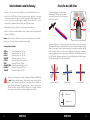
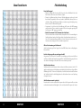
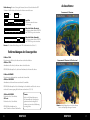
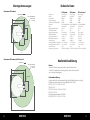
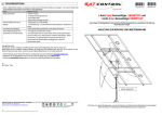
Brillantes Fernsehen Caravanman 65 Premium Caravanman 85 Premium Caravanman 85 Professional Deutsch Benutzerhandbuch und Installationsanleitung Inhaltsverzeichnis Sicherheitshinweise Vorsicht - Unsachgemäße Handhabung kann zu schweren Schäden an diesem Gerät führen. Diese Person kann auch für daraus resultierende weitere Schäden am Gerät verantwortlich gemacht werden. Einführung Sicherheitshinweise.............................................................. 03 Kurzbeschreibung.................................................................. 03 Lieferumfang............................................................................. 03 Systemkomponenten.......................................................... 04 Installation Installation.................................................................................. 05 Klebeanleitung........................................................................ 06 Installation im Innenbereich........................................... 08 Montage des Spiegels......................................................... 08 Anschlussbeispiel................................................................... 09 Das Steuergerät....................................................................... 10 Satellitenübertragung......................................................... 11 Inbetriebnahme und Bedienung................................. 12 Einstellen des LNB Skew.................................................... 13 Hinweis – Lesen Sie das Benutzerhandbuch sorgfältig durch bevor Sie mit der Installation beginnen. Falls Sie schon ähnliche Produkte installiert haben, muss die Vorgehensweise mit diesem Produkt nicht übereinstimmen. Kurzbeschreibung Dieses Gerät ist eine der innovativsten und technologisch fortschrittlichsten SatellitenPositionierungs-Anlagen. Die Antenne verfügt über eine einzigartige Kombination von modernsten Komponenten. Vollen Komfort bietet die schnelle Satellitensuche und eine Kompatibilität mit allen digitalen, HD-fähigen Satelliten Receivern und TV Geräten. Lieferumfang Skew Einstellwerte.................................................................... 14 Fehlerbehebung.......................................................................... 15 Fehlermeldungen des Steuergerätes........................ 16 Ausleuchtzone............................................................................... 17 Montageabmessungen.......................................................... 18 Technische Daten........................................................................ 19 • • • • • • • • • Steuergerät (IDU) inkl. Stromkabel (ca. 1,50 m) Antennenanschlusskabel (10 m) Antennenanschlusskabel (1 m) Steuerkabel (7 m) (Wasserdicht) Dachdurchführung Wetterschutz für Kabelsteckverbindung Montagekleber (optional) Netzteil 230 V (12 V, 5 A) (optional) Bedienungsanleitung Firmwareupdate.......................................................................... 20 Megasat Werke GmbH | Industriestraße 4a | D-97618 Niederlauer | www.megasat.tv | [email protected] 02 DEUTSCH DEUTSCH 03 Systemkomponenten Installation Öffnen Sie die Box und entnehmen Sie das Steuergerät, die Anschlusskabel und das Verpackungsmaterial. Heben Sie die Motoreinheit gerade nach oben aus der Verpackung. Achten Sie beim Hinstellen darauf, dass die Kabel die an der Antenne angebracht sind nicht unter der Grundplatte liegen, um Beschädigungen zu vermeiden. Grundsätzlich empfehlen wir, den Einbau durch Ihren Fachhändler oder eine Fachwerkstatt vornehmen zu lassen! Achtung: Beachten Sie bitte auch, dass sich durch die Antenne die Fahrzeughöhe entsprechend ändert! Bitte halten Sie sich unbedingt an die einzelnen Punkte der Montageanweisung! Allgemeines: Sorgen Sie für einen geeigneten Arbeitsplatz, eine Garage/Halle ist besser als ein Platz im Freien. Die Umgebungstemperatur zur Montage soll zwischen +5° C und max. +25° C liegen. Arbeiten Sie nicht direkt in der Sonne. Halten Sie die Arbeitsvorschriften beim Umgang mit Chemieprodukten ein. Sorgen Sie für die notwendige Arbeitshygiene. Vorbereitung: 1.Vergewissern Sie sich, dass das Dach Ihres Fahrzeugs ausreichend stabil ist. Bei ungenügender oder zweifelhafter Dachstabilität ist ein ca. 2 mm starkes Blech mit ca. 100 x 100 cm auf der Dachaußenhaut zu befestigen. Erkundigen Sie sich dazu bei Ihrem Fahrzeughersteller. Antenneneinheit Der 85 cm (bzw. 65 cm) große Spiegel wird mit wenigen Handgriffen mit der Motoreinheit verschraubt und bildet somit die komplette Antenneneinheit. Der Spiegel wird erst nach der Installation der Motoreinheit angebracht. Steuergerät (IDU) Das Steuergerät dient zur Satellitenauswahl und Steuerung. Es wird zwischen Antenne und Receiver geschaltet und versorgt die Antenne mit Strom. Nach erfolgreicher Ausrichtung schaltet sich das Gerät selbstständig aus. Achtung: Der Caravanman 85 Professional besitzt zusätzlich eine Auto Skew Funktion, die den Polarisationswinkel des LNBs automatisch einstellt und einen weiteren Anschluss für einen zweiten Receiver. 04 DEUTSCH 2.Prüfen Sie, ob alle Teile vorhanden sind. 3.Setzen Sie die Antenne auf den späteren Montageplatz und richten Sie sie so aus, dass der Spiegel und die LNB-Einheit in Richtung Heck des Fahrzeuges zeigen. Achten Sie darauf, dass der Einbauplatz eben ist und keine Dachaufbauten im Weg sind, die den Satellitenempfang stören können. Aufbauten bis zu 20 cm Höhe spielen keine Rolle, höhere Aufbauten sollten einen entsprechenden Abstand zur Antenne haben, damit kein Hindernis zwischen Antenne und Satellit vorhanden ist . Der mindeste Abstand zu einer Klimaanlage sollte 30 cm betragen. 4.Säubern Sie die Montagefläche mit einem geeigneten Reiniger und einem Vliestuch um Schmutz und Unreinheiten zu entfernen. Zeichnen Sie anschließend den Antennenfuß mit einem Stift an. DEUTSCH 05 5.Rauen Sie die gezeichnete Fläche mit Schleifpapier (120er Körnung) leicht an und säubern Sie die Fläche erneut mit dem Reiniger (ACHTUNG: Flächen anschließend nicht mehr berühren) und lassen Sie den Reiniger ca. 10 Minuten ablüften. Klebeanleitung 1.Bereiten Sie den Kleber für die Montage vor. 2.Tragen Sie nun den Kleber auf die Unterseite des Antennenfußes in Schlangenlinien auf, damit der Kleber bis ins Innere gut aushärten kann. 3.Setzen Sie nun sofort (innerhalb von 5 Minuten nach Kleberauftrag) die Antenne auf das angezeichnete Feld. Drücken Sie den Fuß leicht und gleichmäßig an und fixieren Sie die Antenne damit sie nicht verrutscht, z.B. durch ein Klebeband. Es müssen sich nach dem Andrücken noch mindestens 2 mm Kleber zwischen Antennenfuß und Oberfläche befinden. Der Kleber ist nach max. 48 Stunden bei +18° C und einer relativen Luftfeuchte von 50% ausgehärtet. Sollte während der Montagezeit eine geringe Luftfeuchtigkeit herrschen, sprühen Sie nach dem Verkleben in der Umgebung der Antenne immer wieder etwas Wasser in die Luft. 4.Entfernen Sie die evtl. ausgetretene Klebemasse sofort mit einer Spachtel o. ä. und säubern Sie die verunreinigten Flächen mit dem Reiniger und einem Vliestuch. 5.Zur Sicherheit können Sie den Antennenfuß zusätzlich befestigen. Dazu bohren Sie durch die vorhandenen Löcher im Antennenfuß in das Dach Ihres Fahrzeuges und fixieren es durch eine Schraube mit Kontermutter. Damit der frisch verklebte Fuß nicht verrutscht, warten Sie mit dieser Arbeit bis der Kleber ausgehärtet ist. Dachdurchführung: 1.Sofern Sie keine Möglichkeit haben, das Kabel durch eine vorhandene Dachdurchführung zu verlegen, suchen Sie eine geeignete Stelle (am besten im Windschatten hinter der Antenne) auf dem Fahrzeugdach für die Montage der Dachdurchführung, um das Eindringen von Feuchtigkeit (z.B. Regen oder Spritzwasser) im Bohrloch zu vermeiden. Achten Sie darauf, dass die Kabel nicht zu sehr gebogen werden um Signalverlust und eine Beschädigung des Kabels zu vermeiden (kleinster Biegeradius max. 5-7 cm). 2.Zur Installation des Wetterschutzgehäuses für die Kabelsteckverbindung, kleben Sie wie oben beschrieben die Grundplatte auf eine geeignete Stelle Ihres Fahrzeuges. Anschließen verbinden Sie die Anschlusskabel und legen Sie sie in die dafür vorgesehene Aussparung. Stecken Sie nun die Abdeckung auf die Grundplatte und befestigen sie mit den beiliegenden Schrauben. Dichten Sie, wenn nötig, auch hier beide Öffnungen mit dem witterungsbeständigen Silikon ab. 6.Nach der kompletten Montage und Aushärtung des Klebers, kann eine Silikonfuge um den Antennenfuß gezogen werden. 06 DEUTSCH DEUTSCH 07 Installation im Innenbereich 1. Das Steuerkabel und das Koaxialkabel wird im Inneren des Fahrzeuges verlegt. WICHTIG: das Steuerkabel darf hierbei nicht gekürzt werden. 2. Vergewissern Sie sich bei der Wahl des Standortes für das Steuergerät und den SatReceiver, dass beide Geräte an einem trockenen und geschützten Ort stehen. 3. Das Steuergerät und den Sat-Receiver nicht in die Nähe von Wärmequellen stellen und für ausreichend Belüftung sorgen. 4. Im Folgenden werden die grundlegenden Anschlussmöglichkeiten für die Antennenanlage gezeigt: • Verbinden Sie die Stromversorgung (rotes und schwarzes dickes Kabel) für das Steuergerät mit Ihrer Batterie des Fahrzeuges über eine Sicherung (7 Ampere), um einen Kabelbrand bei Kurzschluss zu vermeiden. Das dünne gelbe Kabel wird an den Zündungsplus des Fahrzeuges angeschlossen (Leitung, die nur bei eingeschalteter Zündung 12 Volt führt), und ebenfalls mit einer Sicherung von 7 Ampere abgesichert. Das dünne schwarze Kabel wird an den dazugehörigen Minuspol (Masse) angeschlossen. • Verbinden Sie die Kabel, die von der Antenne kommen, mit dem Steuergerät: - 7 m Steuerkabel mit grünem Stecker in „CONTROL CONNECTOR“ - 10 m Koaxialkabel mit F-Stecker in „ANTENNA“ • Verbinden Sie das Steuergerät mit dem Sat-Receiver: - 1,5 m Koaxialkabel mit F-Stecker von „RECEIVER“ zum Sat-Receiver Montage des Spiegels 1. Schalten Sie das Steuergerät ein. 2. Drücken Sie die SEARCH Taste und warten bis das Rückenteil der Antenne aufgerichtet hat. 3. Entfernen Sie die Stromzufuhr am Steuergerät - der Suchvorgang wird unterbrochen und Sie können nun den Spiegel montieren. 4. Nach der Montage können Sie die Stromzufuhr wieder herstellen und einen normalen Suchlauf starten. 08 DEUTSCH Anschlussbeispiel Zündungsplus Der Caravanman fährt automatisch in den eingeklappten Zustand, sobald der Zündschlüssel gedreht wird. Diese Funktion steht nur zur Verfügung, wenn das Steuergerät ausgeschaltet und Kabel 5 und 6 angeklemmt sind. Im Display des Steuergerätes wird „IGNITION“ angezeigt. Zweiter Anschluss nur bei Caravanman 85 Professional (+) (-) 5 6 5 (-) (+) 4 1 2 3 Steuergerät Stromversorgung DC 12V über Batterie (Pluspol-Dauerversorgung-rot) oder optionales 230V/12V DC Netzteil (Keine Ladegeräte). Achten Sie darauf, dass eine Stromstärke von mind. 5 Ampere gewährleistet ist. Hinweis Das Steuerkabel (7 m) darf nicht gekürzt werden, da dies zu Störungen führen kann. Während des Ausrichtungsvorganges dürfen keine Ladegeräte an der Batterie angeschlossen sein! 1 2 3 4 5 6 Nicht im Lieferumfang enthalten! 3 Receiver Receiver HDMI oder Scart Fernseher HDMI oder Scart Fernseher Information: Die Antenne muss nicht zwingend mit zwei Receivern betrieben werden! Steuerkabel 7 m Koaxialkabel 10 m Koaxialkabel 1 m Pluspol Minuspol Zündungsplus DEUTSCH 09 Das Steuergerät Satellitenübertragung Direct Broadcast Service (DBS) strahlt Audio, Video und Daten über den Satelliten aus, der sich in ca. 36.000 km Höhe über der Erde befindet. Mit einer Empfangsstation wie die Antenne und einem Satelliten Receiver werden die Signale vom Satelliten empfangen und verarbeitet. Das System erfordert eine klare Sicht auf den Satelliten, um den Signalempfang maximal auszunutzen. Vorderansicht des Steuergerätes Gutes Empfangssignal Einschalttaste SD Karte LCD Display Satelliten Auswahltaste Schlechtes Empfangssignal Antenne schließen Rückansicht des Steuergerätes Receiver Antenne RS232 12V DC IN Objekte wie Bäume, Brücken und große Häuser, die sich im Einfallswinkel des Satelliten befinden, führen zu einem Verlust des Signals. Starker Regen, Wolken, Schnee oder Eis kann die Empfangsqualität beeinträchtigen. Wenn das Satellitensignal durch schwere Wetterbedingungen verloren geht, wird das laufende Programm des Receivers beendet (das Bild wird einfrieren, bzw. verschwinden). Wenn die Witterungsverhältnisse wieder einen guten Empfang ermöglichen, wird das TV Bild wieder hergestellt. 123456 Dip Schalter Steuerkabel 12V DC OUT Standard Einstellung für die Dip Schalter 1 2 3 4 5 6 Sollten sich die Dip Schalter nicht in dieser Position befinden, kann die Antenneneinheit nicht automatisch nach einem Satelliten suchen. 10 DEUTSCH DEUTSCH 11 Inbetriebnahme und Bedienung 1.Schalten Sie das Steuergerät ein. Im Display erscheint die aktuelle Firmwareversion. 2.Sobald Sie die SEARCH Taste auf dem Steuergerät drücken, startet der Suchvorgang der Antenneneinheit. Im Display erscheint der eingestellte Satellit (Standardsuche = Astra 19,2° Ost) und die Anzeige beginnt zu blinken. Während dieser Zeit (ca. 5 sek.) können Sie den Satellit mit Hilfe der SEARCH und STOW Taste ändern. Einstellen des LNB Skew Folgende Einstellungen sind nur für den Caravanman 65 / 85 Premium (ohne Auto Skew). Eine Übersicht der Skew Einstellwerte finden Sie auf Seite 14. 3.Nach erfolgreicher Suche schaltet sich das Steuergerät automatisch ab. 0° -90° 4.Wenn Sie die Antenne wieder einfahren möchten, schalten Sie das Steuergerät ein und drücken die STOW Taste. +90° Hinweis: Ein Wechsel des Satelliten ist nur kurz nach dem Einschalten (wie in Punkt 2 beschrieben) oder nach erfolgreicher Satellitensuche möglich. Voreingestellte Satelliten: ASTRA 2 ASTRA 3 ASTRA 1 HOTBIRD ASTRA 4 THOR ATLANTIC BIRD HISPASAT TURKSAT Position für Astra 2 auf 28,2° Ost Position für Astra 3 auf 23,5° Ost Position für Astra 1 auf 19,2° Ost Position für Hotbird auf 13° Ost Position für Astra 4 (Sirius) auf 4,8° Ost Position für Thor auf 0,8° West Position für Atlantic Bird auf 5,0° West Position für Hispasat auf 30° West Position für Türksat auf 42° Ost Während des Suchvorgangs erscheint im Display die Meldung „FAILURE“. Das ist kein defekt der Antenneneinheit. Die Meldung erscheint nur, während die Antenne das gefundene Signal mit den IDs der gespeicherten Satelliten vergleicht. Erkennt die Antenne das Signal und kann es einer der gespeicherten Satelliten zuordnen, erscheint LOCKED im Display. Dieser Vorgang wiederholt sich so lange, bis der von Ihnen gewählte Satellit gefunden wurde. Signale in vertikaler (rot) und horizontaler (blau) Linie haben einen Versatz von genau 90º zueinander. Durch die unterschiedliche Position der Satelliten, abhängig von Ihrem Standort, ist es möglich, dass die Signale nicht genau vertikal und horizontal auf das LNB treffen. Um dieses anzupassen, müssen Sie das LNB in die richtige Lage zu dem ausgesendeten Signal bringen. Diese Anpassung am LNB wird als „Skew Einstellung“ bezeichnet. Die folgende Abbildung zeigt Ihnen die optimale Einstellung des LNBs. Je genauer die Übereinstimmung, desto besser der Empfang. schlechter Empfang guter Empfang bester Empfang LNB Position Satellitensignal 12 DEUTSCH DEUTSCH 13 Skew Einstellwerte Fehlerbehebung Kein Satellitensignal • Objekte wie Bäume, Brücken und große Häuser, die sich im Einfallswinkel des Satelliten befinden, führen zu einem Verlust des Signals. • Wenn das Satellitensignal durch schwere Wetterbedingungen verloren geht, wird das laufende Programm des Receivers beendet (das Bild wird einfrieren, bzw. verschwinden). Wenn die Witterungsverhältnisse wieder einen guten Empfang ermöglichen, wird das TV Bild wieder hergestellt. • Vergewissern Sie sich, dass in den Einstellungen des Receivers die LNB Spannung eingeschalten ist. Dieses wird mit der grünen LED am Steuergerät angezeigt (LED leuchtet grün = LNB Spannung vorhanden). • Nur bei Caravanman 65 / 85 Premium (ohne AutoSkew) Sollte die Antenne keinen Satelliten finden, überprüfen Sie die Skeweinstellung des Satelliten für ihren Standort. Eine Übersicht der Skew Einstellwerte finden Sie auf Seite 14. Die Grundeinstellung des LNBs ist 0 Grad. Sollte diese laut Liste mehr als 5 Grad abweichen, korrigieren Sie die Gradzahl entsprechend. Gibt es Verschmutzung auf der Antenne? Starke Verschmutzung auf dem Spiegel oder dem LNB Gehäuse kann zu Empfangsproblemen führen. Ist alles richtig angeschlossen und eingeschaltet? Vergewissern Sie sich, dass der TV und der Receiver richtig angeschlossen und der Receiver für den Satellitenempfang richtig eingestellt ist. Sind alle Kabel richtig angeschlossen oder hat die Verbindungen eine andere Person versehentlich gelockert? Satelliten Ausleuchtzone Satelliten sind in festen Positionen über dem Äquator im Orbit positioniert. Um die TV Signale zu empfangen, muss der Empfangsort innerhalb der Ausleuchtzone liegen. Mit der Abbildung auf Seite 17 können Sie überprüfen, ob sich Ihr Standort in der Ausleuchtzone des Satelliten befindet. In den Randgebieten der Ausleuchtzone kann es zu Empfangsstörungen kommen. Satellitenfrequenz wurde geändert Fernsehsender wechseln vereinzelt Ihre Frequenz die mit der Frequenz im Receiver dann nicht mehr übereinstimmt. Erkundigen Sie sich nach der aktuellen Frequenz des Senders. 14 DEUTSCH DEUTSCH 15 Notbedienung: Bei einer Störung der Antenne, können Sie durch ändern der DIP Schalter auf der Rückseite des Gerätes, die Antenne manuell steuern. hoch 1 1 1 2 2 2 Ausleuchtzone Caravanman 65 Premium runter 3 3 3 4 4 4 5 5 5 6 Cycle Test Die Antenne simuliert einen Suchvorgang. 6 Manueller Modus (Elevation) Die Antenne kann über die SEARCH und STOW Taste gesteuert werden. 6 Manueller Modus (Azimuth) Die Antenne kann über die SEARCH und STOW Taste gesteuert werden. Hinweis: Die Standard Einstellungen der DIP Schalter finden Sie auf Seite 10. Fehlermeldungen des Steuergerätes EL Motor STALL Elevationsmotor blockiert, die Antenne kann sich nicht aufrichten. AZ Motor STALL Azimuthmotor blockiert, die Antenne kann sich nicht drehen. Caravanman 85 Premium / 85 Professional LÖSUNG: Bitte überprüfen Sie, dass keine Hindernisse die Antenne blockieren. EL Motor NO POWER Elevationsmotor bekommt keine ausreichende Stromzufuhr. AZ Motor NO POWER Azimuthmotor bekommt keine ausreichende Stromzufuhr. LÖSUNG: Bitte überprüfen Sie die Verbindung des Steuerkabels und/oder ob eine ausreichende Stromversorgung für die Antenne vorhanden ist (12 V, 5 A). SK Motor NO POWER Fehler in der Auto Skew Einheit SK Count Fehler in der Auto Skew Einheit LÖSUNG: Bitte kontaktieren Sie einen Techniker von Ihrem Fachhändler. 16 Hinweis: Nach einer Fehlermeldung muss die Stromzufuhr des Steuergerätes getrennt und wieder hergestellt werden, um eine weitere Bedienung zu ermöglichen. DEUTSCH Hinweis: In den Randgebieten der Ausleuchtzone kann es zu Empfangsstörungen kommen. DEUTSCH 17 Montageabmessungen Caravanman 65 Premium Fahrtrichtung Max. Schwenkradius ab einer Höhe von 20 cm 82 cm 71 cm 39 cm 66 cm Drehpunkt 39 cm Technische Daten 65 Premium 85 Premium 85 Professional Antennen Typ LNB Typ Frequenz Band Antenna Verstärkung Ausleuchtzone (Minimum EIRP) Polarisation Motor Neigungswinkel (Elevation) Suchwinkel (Azimuth) Neigungsgeschwindigkeit Drehgeschwindigkeit Lagertemperaturbereich Betriebstemperaturbereich Stromversorgung Leistungsaufnahme im Suchmodus Leistungsaufnahme im Standby Antennen Gewicht Abmessungen (geschlossen) Off-Set Spiegel Single LNB Ku Band 37 dBi 46 dBW V/H oder RHCP/LHCP 2-Achen Motor 0° bis 70° 360° 6° pro Sekunde 13° pro Sekunde -20° bis 70° -20° bis 50° 12 V DC 5A 12 V / 20-30 Watt 12 V / 0,01 Watt 14 kg 82 x 66 x 19 cm (L/B/H) Off-Set Spiegel Single LNB Ku Band 39 dBi 44 dBW V/H oder RHCP/LHCP 2-Achen Motor 0° bis 70° 360° 6° pro Sekunde 13° pro Sekunde -20° bis 70° -20° bis 50° 12 V DC 5A 12 V / 20-30 Watt 12 V / 0,01 Watt 15 kg 102 x 85 x 19 cm (L/B/H) Off-Set Spiegel Twin LNB Ku Band 39 dBi 44 dBW V/H oder RHCP/LHCP 2-Achen Motor 0° bis 70° 360° 6° pro Sekunde 13° pro Sekunde -20° bis 70° -20° bis 50° 12 V DC 5A 12 V / 20-30 Watt 12 V / 0,01 Watt 15 kg 102 x 85 x 19 cm (L/B/H) 125 cm Konformitätserklärung Caravanman 85 Premium / 85 Professional Fahrtrichtung Max. Schwenkradius ab einer Höhe von 20 cm 99 cm 88 cm 39 cm 82 cm Drehpunkt 39 cm Hinweis: Gewicht und Abmessungen sind nicht die absolut exakten Werte. Technische Details können jederzeit geändert werden (nach Hersteller) ohne vorherige Ankündigung. Konformitätserklärung Hiermit wird die Übereinstimmung mit folgenden Richtlinien/Normen bestätigt: Richtlinie zur elektromagnetischen Verträglichkeit 2004/108/EG EN 55013: 2001 + A1: 2003 + A2: 2006 EN 55020: 2007 EN 61000-3-2:2006 + A1:2009 + A2:2009 EN 61000-3-3:2008 Niederspannungsrichtlinie 2006/95/EG EN 60065: 2002 + A1: 2006 + A11: 2008 165 cm 18 DEUTSCH DEUTSCH 19 Firmware Update Wenn die Frequenz, auf der die Antenne den Satelliten idendifiziert, abgeschaltet wird, muss ein Firmwareupdate des Steuergerätes durchgeführt werden. Die aktuelle Firmware Version des Steuergerätes können Sie in den ersten 3 Sekunden nach dem Einschalten im unteren Bereich des Displays ablesen. Updatevorgang: 1.Schalten Sie das Steuergerät ein. 2.Stecken Sie die SD Karte in den Slot auf der Vorderseite des Steuergerätes. 3.Folgendes erscheint im Display: Bitte erkundigen Sie sich auf unserer Homepage nach der aktuellsten Firmware Version. SD CARD DETECTED WRITING SOFTWARE Vorbereitung der SD Karte: 4.Nachdem die Software kopiert wurde, erscheint folgende Meldung: SD CARD Bevor Sie die SD Karte benutzen, formatieren Sie sie auf “FAT32“ LOAD COMPLETE 5.Entfernen Sie nun die SD Karte. 6.Die Firmware ist nun aktualisiert. Nachdem Sie die SD Karte formatiert haben, kopieren Sie die neue Software darauf. 20 DEUTSCH DEUTSCH 21 Brillantes Fernsehen Caravanman 65 Premium Caravanman 85 Premium Caravanman 85 Professional Englisch Stand: v2.0 Juni 2013 User manual and installation instruction Contents Safety Information Caution – Improper handling by unqualified personnel can cause serious damage to this equipment. Unqualified personnel who tamper with this equipment may be held liable for any resultant damage to the equipment. Introduction Safety Information................................................................. 03 Short description.................................................................... 03 Delivery......................................................................................... 03 System Components........................................................... 04 Installation Installation.................................................................................. 05 Gluing instructions................................................................ 06 Indoor installation.................................................................. 08 Assembly the dish.................................................................. 08 Connection................................................................................ 09 Control unit................................................................................ 10 Satellite broadcasting.......................................................... 11 Startup and operation......................................................... 12 Setting the LNB skew........................................................... 13 Note – Before you begin, carefully read each of the procedures in this manual. If you have not performed similar operations on comparable equipment, do not attempt to perform these procedures. Short description The satellite antenna system is the innovative and a technologically advanced satellite Positioner system. The antenna has a unique combination of cutting-edge components. Fast satellite search and compatibility with all digital, HD-ready set-top boxes and TV sets are guaranteed. Delivery Skew Settings................................................................................. 14 Troubleshooting.......................................................................... 15 Error messages of the control unit.............................. 16 Footprint............................................................................................ 17 Mounting Dimensions............................................................ 18 Specifications................................................................................. 19 • • • • • • • • • Control unit (IDU) incl. powercable (ca. 1,50 m) Antenna cable (10 m) Antenna cable (1 m) Control cable (7 m) (water resistant) Roof outlet Weather protection for cable connector mounting glue (optional) Power supply 230 V (12 V, 5 A) (optional) User manual Firmwareupdate.......................................................................... 20 Megasat Werke GmbH | Industriestraße 4a | D-97618 Niederlauer | www.megasat.tv | [email protected] 02 ENGLISH ENGLISH 03 System components Installation Open box and remove the control unit, cables and packing material. Lift the antenna straight up out of the box. Never place the system upside down!. When you lay down the antenne, pmake sure that the cable attached to the antenna not be below the base plate to prevent damages. Basically, we recommend that you leave the installation to make by your dealer or workshop! Warning: Please also note that the antenna height of the vehicle will change accordingly! Please strictly adhere to the various points in the installation instructions! General Information: Provide a suitable working environment, a garage/warehouse is better than open air. The ambient temperature for installation is between +5° C and max. +25° C. Work not directly in the sun. Comply with the safety regulations when handling with chemical products. Provide the necessary hygiene. Preparation: 1.Make sure that the roof of your vehicle is sufficiently stable. In case of insufficient or doubtful roof stability is an approximately 2 mm thick plate with 100 x 100 cm is to be attached to the outer roof skin. Ask to your vehicle manufacturer. Antenna unit The 85 cm (or 65 cm) wide dish is screwed in a few steps to the motor unit, thus forming the complete antenna unit. The mirror is mounted only after the installation of the motor unit. Control unit (IDU) The control unit is used for satellite selection and control. It is connected between the antenna and the set-top box and supplied the antenna with electricity. After successful alignment, the device switches off automatically. Warning: The Caravanman 85 Professional has an additional Auto Skew function that adjust the polarization angle of the LNB automatically, and a additional connection for a second set-top box. 04 ENGLISH 2.Make sure that all parts are present. 3.Place the antenna on the later assembly area and align it so that the mirror and the LNB unit pointing towards the rear of the vehicle. Make sure that the slot is flat and no roof structures in the way that can interfere with satellite reception. Constructions up to 20 cm in height do not matter, higher ups should have a corresponding distance to the antenna, so that no obstacle exists between the antenna and the satellite. The least distance to an air conditioner should be 30 cm. 4.Clean the mounting surface with a suitable cleaner and a fleece cloth to remove dirt and impurities. Then draw the antenna feet with a pen. ENGLISH 05 1.Roughen the drawn areas and feet with sandpaper (120 grit) to easily and thoroughly clean the surface again with cleaner (WARNING: then no longer touch areas) and let the clean dry for about 10 minutes.. Gluing instructions 1.Prepare the glue for mounting. 2.Now take the glue on the underside of the antenna base in serpentine lines, so that the glue can harden well to the inside. 3.Now place immediately (within 5 minutes after adhesive application), the antenna on the marked fields. Press your feet slightly and evenly and fix the antenna so that it stays in place, eg by an adhesive tape. It must be after pressing for at least 2 mm glue between antenna and surface. The adhesive is cured max. in 48 hours at +18° C and a relative humidity of 50%. Should prevail low humidity during the assembly time, spray after bonding in the vicinity of the antenna always some water in the air. Roof outlet: 1.If you have no way to feed the cable through an existing Roof outlet, seek a suitable place (best in the slipstream behind the antenna) on the roof for the installation of the Roof outlet to prevent ingress of moisture (eg rain or splashing) in to avoid borehole. Make sure that the cable is not bent too much signal loss and to avoid damaging the cable (bending radius max. 5-7 cm). 2.To install the weatherproof housing for the cable connector, glue as described above, the base plate to a suitable location of your vehicle. Connect the connecting cable and insert it into the slot provided. Now put the cover on the base plate and fix it with the screws. Seal openings here both with the weather-resistant silicone material. 4.Remove any spilled adhesive immediately with a putty knife or similar and clean the soiled surfaces with the cleaner and a fleece cloth. 5.For safety, you can attach the antenna base additionally. Given by drill through the existing hole in the respective antenna to the roof of your car and fix it with a screw with locking nut. In order for the freshly bonded feet can not slip, wait with this work until the adhesive has cured. 6.After the complete assembly and curing of the adhesive, a silicone can be drawn around the antenna bases. 06 ENGLISH ENGLISH 07 Indoor installation 1. The control cable and coaxial cable is routed inside the vehicle. IMPORTANT: The control cable must not be shortened. 2. Make sure when you choosing a location for the control unit and the set-top box that both devices are in a dry and a protected place. Connection Zündungsplus The Caravanman automatically moves to the folded state when the ignition key is turned. This function is only available when the controller is turned off and cables 5 and 6 are connected. The control unit displayed „IGNITION“. 3. Do not place the control unit and the set-top box close to heat sources and ensure sufficient ventilation. 4. Below are the basic connections for the antenna system are shown: • Connect the power supply (red and black thick cable) for the control unit to your car battery via a fuse (7 amps) to avoid a cable fire at short circuit. The yellow cable is connected to the ignition plus of the vehicle (12 volts line only when the ignition leads), and also protected with a fuse of 7 amps. The remaining black wire is connected to the corresponding negative (ground). • Connect the cables coming from the antenna to the control unit: - 7 m Control cable with green connector into „CONTROL CONNECTOR“ - 10 m Coaxial cable with F-connector in „ANTENNA“ • Connect the control unit to the set-top box: - 1,5 m Kcoaxial cable with F-connector from „RECEIVER“ to set-top box. Assembly the dish 1. Turn on the control unit. 2. Press the SEARCH button and wait until the back part of the antenna is erected. 3. Remove the power supply to the control unit - the search is interrupted and you can now assembly the dish. 4. After assembly the dish you can connect the power supply back on and start a normal scan. 08 ENGLISH Second connection only 85 Caravanman Professional (+) (-) 5 6 5 (-) (+) 4 1 2 3 Control unit not in Included! Power supply 12V DC via battery (positive-permanent systems) or optional DC power supply 230V/12V (no charger). Ensure that a current is assured of at least 5 amps. Note The control cable (7 m) can not be reduced, because that can cause interference. During the registration process may not be connected to the battery charger! 1 2 3 4 5 6 3 set-top box set-top box HDMI or Scart HDMI or Scart TV TV Information: The antenna does not have to necessarily be operated with two receivers! Control cable 7 m Coaxial cable 10 m Coaxial cable 1 m Positive pole Minus pol Plus ignition ENGLISH 09 Satellite broadcasting Control Unit Direct Broadcast Service (DBS) satellites broadcast audio, video and data information from satellites located ca. 22.000 miles in space. A receiving station, such as the antenna, should include a dish and satellite receiver to receive the signals and process them for use by the consumer audio and video equipment. The system requires a clear view of the satellite to maximize the signal reception. Frontpanel of the control unit good reception signal Power S/W SD Card LCD Display Satellite select button bad reception signal Stow button Rearpanel of the control unit set-top box antenna RS232 12V DC IN Objects such as tall lighthouse, bridges and big ship that block this view will cause a loss of signal. The signal will be quickly restored once the antenna has a clear line of sight again. Heavy rain, cloud, snow or ice may also interfere with the signal reception quality. If the satellite signal is lost due to blockage or severe weather condition, services from the receiver will be lost (picture will freeze frame and may disappear). When the satellite signal strength is again high enough, then the receiver will resume providing desired programming services. 123456 DIP switch control cable 12V DC OUT Default setting for the DIP switch 1 2 3 4 5 6 Should not be the DIP switches in this position, the antenna unit can not search automatically for a satellite. 10 ENGLISH ENGLISH 11 Startup and operation 1.Turn on the control unit. The current firmware version will be displayed. 2.When you press the SEARCH button on the control unit the search process of the antenna unit starts. The adjusted satellite (Astra standard search = 19.2 ° East) appears in the display and the display starts flashing. During this time (approx. 5 sec.) You can change the satellite, using the SEARCH and STOW button. Setting the LNB Skew The following settings are only for the Caravanman 65 / 85 Premium (without AutoSkew). An overview of the skew settings can be found on page 14. 3.After a successful search, the control unit switch off automatically. 0° -90° 4.If you want to retract the antenna back, turn on the controller and press the STOW button. +90° Note: Changing the satellite is only possible shortly after switching on the power (as described in point 2) or after successful satellite search. Preprogrammed satellites: ASTRA 2 ASTRA 3 ASTRA 1 HOTBIRD ASTRA 4 THOR ATLANTIC BIRD HISPASAT TURKSAT Position for Astra 2 at 28,2° Ost Position for Astra 3 at 23,5° Ost Position for Astra 1 at 19,2° Ost Position for Hotbird at 13° Ost Position for Astra 4 (Sirius) at 4,8° Ost Position for Thor at 0,8° West Position for Atlantic Bird at 5,0° West Position for Hispasat at 30° West Position for Türksat at 42° Ost During the search, the display shows the message „FAILURE“ appears. This is not a defect of the antenna unit. The message only appears while the antenna compares the detected signal with the IDs of stored satellites. Recognizes the signal and the antenna can assign it one of the stored satellites, LOCKED appears on the display. This process is repeated until the area you choose satellite is found. Signals in the vertical (red) and horizontal (blue) line have an offset of exactly 90° to each other. Due to the different position of the satellites, depending on your location, it is possible that the signals do not meet exactly vertically and horizontally on the LNB. To adjust this, turn the LNB into the correct position to the transmitted signal. This adjustment to the LNB is called „skew adjustment“. The following figure shows the optimal setting of the LNB. More accurate the match, the better of reception. bad reception good reception best reception LNB Position Satellite signal 12 ENGLISH ENGLISH 13 Skew Settings Troubleshooting No Signal • Objects such as trees, bridges, and large buildings, which are located in the angle of the satellite will lead to a loss of the signal. • If the satellite signal is lost through severe weather conditions, the current program of the receiver is stopped (the image freeze, or disappear). If the weather conditions allow a good reception again, the TV screen will be restored. • Make sure that the settings of the set-top box to LNB voltage is switched on. This is indicated by the green LED on the control unit (LED green = LNB voltage present). • Only Caravanman 65 / 85 Premium (without AutoSkew) If the antenna has not found satellites, check the Skew settings for the satellite at your location. An overview of the skew settings can be found on page 14. The basic setting of the LNB is 0°. Should they deviate more than 5°, adjust the degrees accordingly. There is dirt on the antenna? Excessive dirt on the housing may cause reception problems. Everything is properly connected and turned on? Your satellite TV receiver might be set up incorrectly or defective. First check the receiver’s configuration to ensure it is set up for the desired programming. In the case of a faulty receiver, refer to your selected receiver’s user manual for service and warranty information. Satellite footprint Television satellites are located in fixed positions above the Earth’s equator and beam TV signals down to certain regions of the planet (not worldwide). To receive TV signals from a satellite, you must be located within that satellite’s unique coverage area. With the figure on page 17, you can check if you are located in the footprint of the satellite. In the outlying areas of the footprint there may be interference. Satellite Frequency Data Changed If some channels work, while one or more other channels do not, or if the antenna cannot find the selected satellite, the satellite’s frequency data might have changed. 14 ENGLISH ENGLISH 15 Notbedienung: Bei einer Störung der Antenne, können Sie durch ändern der DIP Schalter auf der Rückseite des Gerätes, die Antenne manuell steuern. up 1 1 1 2 2 2 Footprint Caravanman 65 Premium down 3 3 3 4 4 4 5 5 5 6 Cycle Test The antenna simulates the search. 6 Manueller Modus (Elevation) The antenna can be controlled via the SEARCH and STOW button. 6 Manueller Modus (Azimuth) The antenna can be controlled via the SEARCH and STOW button. Note: The default settings of the DIP switch, see page 10. Error messages of the control unit EL Motor STALL Elevation motor blocked, the antenna can not straighten up. AZ Motor STALL Azimuth motor blocked, the antenna can not turn. Caravanman 85 Premium / 85 Professional SOLUTION: Bitte überprüfen Sie, dass keine Hindernisse die Antenne blockieren. EL Motor NO POWER Elevation motor receiving sufficient power. AZ Motor NO POWER Azimuth motor receiving sufficient power. SOLUTION: Please check the connecting of the control cable and/or whether an adequate power supply for the antenna is present (12 V, 5 A) SK Motor NO POWER Skew errors of the Auto Skew unit SK Count Skew errors of the Auto Skew unit SOLUTION: Please contact a technician of your local dealer. 16 Note: After an error of the power supply, the control unit must be disconnected and connected again to enable a further operation. ENGLISH Note: In the outlying areas of the footprint there may be interference. ENGLISH 17 Mounting dimensions Caravanman 65 Premium direction of travel max. radius at height of 20 cm 82 cm 71 cm 39 cm 66 cm Rotation 39 cm Specifications 65 Premium 85 Premium Antennen Typ LNB Typ Frequency Band Antenna Gain Footprint (Minimum EIRP) Polarization Motor Elevation Range Azimuth Range Tilt speed Rotation speed Storage temperature range Operating Temperature Range Power Power consumption in use Power consumption in standby Antenna Weight Dimensions (closed) Off-Set dish Single LNB Ku Band 37 dBi 46 dBW V/H or RHCP/LHCP 2-Axis Motor 0° to 70° 360° 6° / sec. 13° / sec. -20° to 70° -20° to 50° 12 V DC 5A 12 V / 20-30 W 12 V / 0,01 W 14 kg 82 x 66 x 19 cm (L/W/H) Off-Set dish Off-Set dish Single LNB Twin LNB Ku Band Ku Band 39 dBi 39 dBi 44 dBW 44 dBW V/H or RHCP/LHCP V/H or RHCP/LHCP 2-Axis Motor 2-Axis Motor 0° to 70° 0° to 70° 360° 360° 6° / sec. 6° / sec. 13° / sec. 13° / sec. -20° to 70° -20° to 70° -20° to 50° -20° to 50° 12 V DC 5A 12 V DC 5A 12 V / 20-30 W 12 V / 20-30 W 12 V / 0,01 W 12 V / 0,01 W 15 kg 15 kg 102 x 85 x 19 cm (L/W/H) 102 x 85 x 19 cm (L/W/H) 85 Professional 125 cm Caravanman 85 Premium / 85 Professional direction of travel max. radius at height of 20 cm 99 cm 88 cm 39 cm 82 cm Rotation 39 cm Declaration of Conformity Note: Weight and dimensions are not absolutely exact values. Technical details can be changed at any time (according to manufacturer) without prior notice. Declaration of Conformity This complies with the following directives / standards is confirmed: Electromagnetic Compatibility Directive 2004/108/EC EN 55013: 2001 + A1: 2003 + A2: 2006 EN 55020: 2007 EN 61000-3-2:2006 + A1:2009 + A2:2009 EN 61000-3-3:2008 Low Voltage Directive 2006/95/EG EN 60065: 2002 + A1: 2006 + A11: 2008 165 cm 18 ENGLISH ENGLISH 19 Firmware Update When the frequency is switched off, on which the antenna idendifiziert the satellite, you must update the firmware of the control unit. The current firmware version of the control unit, you can read on the bottom of the screen in the first 3 seconds after switching on. Update process: 1.Turn on the controller. 2.Insert the SD card into the slot on the front side of the control unit. 3.The following will appear in the display: Please check our website for the latest firmware version. SD CARD DETECTED WRITING SOFTWARE Preparing the SD card: 4.After the software is copied, the following message appears: SD CARD Before you use the SD card, format it to „FAT32“ LOAD COMPLETE 5.Now remove the SD card. 6.The firmware is updated now. After you format the SD card, copy the new software on it. 20 ENGLISH ENGLISH 21 Status: v2.0 Juni 2013