1
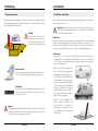
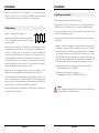
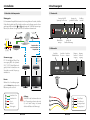
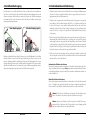
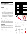
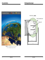
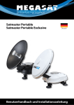
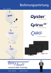
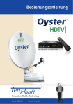
Caravanman Kompakt Bedienungsanleitung Inhaltsverzeichnis 1. Einführung 1.1 Sicherheitshinweise Vorsicht: Unsachgemäße Handhabung kann zu schweren Schäden an diesem Gerät führen. Die Verantwortlichen können auch für daraus resultierende weitere Schäden am Gerät verantwortlich gemacht werden. 1. Einführung 1.1 Sicherheitshinweise................................................................................. 03 1.2 Kurzbeschreibung..................................................................................... 03 1.3 Lieferumfang................................................................................................ 03 1.4 Systemkomponenten............................................................................. 04 2. Installation 2.1 Installation auf dem Dach.................................................................... 05 2.2 Klebeanleitung............................................................................................ 06 2.3 Installation im Innenbereich.............................................................. 07 2.4 Anschluss der Komponenten............................................................ 08 3. Steuergerät 2.1 Frontansicht.................................................................................................. 09 2.2 Rückansicht................................................................................................... 09 Hinweis: Lesen Sie das Benutzerhandbuch sorgfältig durch bevor Sie mit der Installation beginnen. Falls Sie schon ähnliche Produkte installiert haben, muss die Vorgehensweise mit diesem Produkt nicht übereinstimmen. 1.2 Kurzbeschreibung Dieses Gerät ist eine der innovativsten und technologisch fortschrittlichsten Satellitenpositionierungsanlagen. Die Antenne verfügt über eine einzigartige Kombination von modernsten Komponenten. Vollen Komfort bietet die schnelle Satellitensuche und eine Kompatibilität mit allen digitalen Satellitenreceivern und Fernsehgeräten. 1.3 Lieferumfang 4. Satellitenübertragung................................................................................ 10 5. Inbetriebnahme und Bedienung........................................................ 11 6. Fehlerbehebung............................................................................................... 12 7. Einstellwerte für den Skew...................................................................... 13 8. Ausleuchtzone.................................................................................................... 14 Caravanman Kompakt • • • • • • Steuergerät inkl. Stromkabel 1x Antennenanschlusskabel (10 m) 1x Antennenanschlusskabel (1 m) Montagekleber (optional) Netzteil 230 V (12 V, 5 A) (optional) Bedienungsanleitung Caravanman Kompakt Twin • Steuergerät inkl. Stromkabel • 1x Antennenanschlusskabel (10 m) • 1x Antennenanschlusskabel (1 m) • Montagekleber (optional) • Netzteil 230 V (12 V, 5 A) (optional) • Bedienungsanleitung 9. Montageabmessungen............................................................................... 15 10. Technische Daten.......................................................................................... 16 02 DEUTSCH DEUTSCH 03 2. Installation 1. Einführung 1.4 Systemkomponenten 2.1 Installation auf dem Dach Öffnen Sie den Karton und entnehmen Sie das Steuergerät, die Anschlusskabel und das Verpackungsmaterial. Heben Sie die Antenne gerade nach oben aus dem Karton. Stellen Sie die Anlage niemals auf den Kopf! Achtung: Fassen Sie die Antenne niemals direkt am Spiegel an, wenn Sie sie aus dem Karton heben. Heben Sie die Antenne an der Grundplatte an. Grundsätzlich empfehlen wir den Einbau durch Ihren Fachhändler oder eine Fachwerkstatt vornehmen zu lassen! Achtung: Beachten Sie bitte auch, dass sich durch die Antenne die Fahrzeughöhe entsprechend ändert! Bitte halten Sie sich unbedingt an die einzelnen Punkte der Montageanweisung! Allgemeines: Sorgen Sie für einen geeigneten Arbeitsplatz, eine Garage/Halle ist besser als ein Platz im Freien. Die Umgebungstemperatur zur Montage soll zwischen +5° C und max. +25° C liegen. Arbeiten Sie nicht direkt in der Sonne. Halten Sie die Arbeitsvorschriften beim Umgang mit Chemieprodukten ein. Sorgen Sie für die notwendige Arbeitshygiene. Vorbereitung: 1.Vergewissern Sie sich, dass das Dach Ihres Fahrzeugs ausreichend stabil ist. Bei ungenügender oder zweifelhafter Dachstabilität ist ein ca. 2 mm starkes Blech mit ca. 100 x 100 cm auf der Dachaußenhaut zu befestigen. Erkundigen Sie sich dazu bei Ihrem Fahrzeughersteller. Antenneneinheit Die 45 cm Hochleistungsantenne und der Elevationswinkel von 15-62° ermöglicht bestmöglichen Empfang in ganz Europa. Steuergerät Das Steuergerät dient zur Satellitenauswahl und Steuerung. Es wird zwischen Antenne und Receiver geschaltet und versorgt die Antenne mit Strom. Hinweis: Der Caravanman Kompakt Twin besitzt zusätzlich einen weiteren Anschluss für einen zweiten Receiver. Für den korrekten Anschluss der Komponenten beachten Sie bitte das Anschlussdiagramm auf Seite 8. 04 DEUTSCH 2.Prüfen Sie, ob alle Teile vorhanden sind. 3.Setzen Sie die Antenne auf den späteren Montageplatz und richten Sie sie so aus, dass der Spiegel und die LNB-Einheit in Richtung Heck des Fahrzeuges zeigen. Achten Sie darauf, dass die Montagefläche eben ist und keine Dachaufbauten im Weg sind. Beachten Sie unbedingt die Montageabmessungen auf Seite 16. Der mindeste Abstand zu einer Klimaanlage sollte 30 cm betragen. 4.Säubern Sie die Montagefläche mit einem geeigneten Reiniger und einem Vliestuch um Schmutz und Unreinheiten zu entfernen. Zeichnen Sie anschließend den Antennenfuß mit einem Stift an. DEUTSCH 05 2. Installation 2. Installation 5.Rauen Sie die gezeichnete Fläche mit Schleifpapier (120er Körnung) leicht an und säubern Sie die Fläche erneut mit dem Reiniger (ACHTUNG: Flächen anschließend nicht mehr berühren) und lassen Sie den Reiniger ca. 10 Minuten ablüften. 1.Das Koaxialkabel wird im Inneren des Fahrzeuges verlegt. 2.Vergewissern Sie sich bei der Wahl des Standortes für das Steuergerät und den Sat-Receiver, dass beide Geräte an einem trockenen und geschützten Ort stehen. 2.2 Klebeanleitung 1.Bereiten Sie den Kleber für die Montage vor. 2.Tragen Sie nun den Kleber auf die Unterseite des Antennenfußes in Schlangenlinien auf, damit der Kleber bis ins Innere gut aushärten kann. 3.Setzen Sie nun sofort (innerhalb von 5 Minuten nach Kleberauftrag) die Antenne auf das angezeichnete Feld. Drücken Sie den Fuß leicht und gleichmäßig an und fixieren Sie die Antenne, damit sie nicht verrutscht, z.B. durch ein Klebeband. Es müssen sich nach dem Andrücken noch mindestens 2 mm Kleber zwischen Antennenfuß und Oberfläche befinden. Der Kleber ist nach max. 48 Stunden bei +18° C und einer relativen Luftfeuchte von 50% ausgehärtet. Sollte während der Montagezeit eine geringe Luftfeuchtigkeit herrschen, sprühen Sie nach dem Verkleben in der Umgebung der Antenne immer wieder etwas Wasser in die Luft. 4.Entfernen Sie die evtl. ausgetretene Klebemasse sofort mit einer Spachtel o. ä. und säubern Sie die verunreinigten Flächen mit dem Reiniger und einem Vliestuch. 5.Zur Sicherheit können Sie den Antennenfuß zusätzlich befestigen. Dazu bohren Sie durch die vorhandenen Löcher im Antennenfuß in das Dach Ihres Fahrzeuges und fixieren es durch eine Schraube mit Kontermutter. Damit der frisch verklebte Fuß nicht verrutscht, warten Sie mit dieser Arbeit bis der Kleber ausgehärtet ist. 6.Nach der kompletten Montage und Aushärtung des Klebers, kann eine Silikonfuge um den Antennenfuß gezogen werden. 06 2.3 Installation im Innenbereich DEUTSCH 3.Das Steuergerät und den Sat-Receiver nicht in die Nähe von Wärmequellen stellen und für ausreichend Belüftung sorgen. 4.Im Folgenden werden die grundlegenden Anschlussmöglichkeiten für die Antennenanlage gezeigt: • Verbinden Sie die Stromversorgung (rot-schwarzes Kabel) für das Steuergerät mit Ihrer Batterie des Fahrzeuges über eine Sicherung (7 Ampere), um einen Kabelbrand bei Kurzschluss zu vermeiden. Das gelbe Kabel wird an dem Zündungsplus des Fahrzeuges angeschlossen und ebenfalls mit einer Sicherung von 7 Ampere abgesichert (Dieses Kabel muss nur angeschlossen werden, wenn die Antenne automatisch bei Motorstart einfahren soll.). Das übrig bleibende schwarze Kabel wird an den dazugehörigen Minuspol der Zündungsanlage (Masse) angeschlossen. • Verbinden Sie das Kabel, das von der Antenne kommt, mit dem Steuergerät: - 10 m Koaxialkabel mit F-Stecker in „ANTENNA“ • V erbinden Sie das Steuergerät mit dem Sat-Receiver: - 1 m Koaxialkabel mit F-Stecker von „RECEIVER“ zum Sat-Receiver Hinweis: Beim Caravanman Kompakt Twin schließen Sie ein zweites Koaxialkabel von der Antenne direkt an den zweiten Sat-Receiver an. DEUTSCH 07 3. Das Steuergerät 2. Installation 2.4 Anschluss der Komponenten 3.1 Frontansicht Zündungsplus Der Caravanman Kompakt fährt automatisch in den eingefahrenen Zustand, sobald der Zündschlüssel gedreht wird. Diese Funktion steht nur zur Verfügung, wenn das Steuergerät eingeschaltet und Kabel 4 und 5 angeklemmt sind. Sobald die Antenne eingefahren ist, leuchten am Steuergerät die LEDs der Satelliten nacheinander auf. F-Anschluss OHNE Markierung Anzeige der LNB Spannung vom Receiver LNB 5 4 (-) (+) 3 POWER POWER Hinweis Während des Ausrichtungsvorganges dürfen keine Ladegeräte an der Batterie angeschlossen sein! 1 2 3 4 5 Bereitschaftsanzeige 1 Stromversorgung DC 12 V über Batterie (Pluspol Dauerversorgung ROT) oder optionales 230 V / 12 V DC Netzteil (Keine Ladegeräte). Achten Sie darauf, dass eine Stromstärke von mind. 5 Ampere gewährleistet ist. Koaxialkabel 10 m Koaxialkabel 1 m Pluspol Minuspol Zündungsplus ASTRA2 ASTRA1 ASTRA4 HISPASAT / TURKSAT OFF F-Anschluss MIT Markierung Zweiter Anschluss nur bei Caravanman Kompakt Twin Steuergerät LOCK ASTRA3 HOTBIRD SATELLITE SELECTION Eingang Stromversorgung Ausgang Stromversorgung Anzeige für Satellitenerkennung Anschluss Einfahrfunktion Anschluss Anschluss Receiver Antenne Nicht im Lieferumfang enthalten! Receiver RS-232 Fernseher THOR 3.2 Rückansicht 2 Receiver Satellitenauswahl ON (+) (-) 4 Anzeige des gewählten Satelliten RECEIVER ANTENNA IN OUT DC 12~24 V Fernseher Achtung: Schließen Sie das Gerät immer über eine mit 7 Ampere abgesicherte, und mind. 2,5 mm² starke Leitung an (niemals direkt an die Batterie des Fahrzeuges). 1 1 2 3 4 2 3 12 Volt Pluspol 12 Volt Minuspol Zündungsminuspol Zündungspluspol 4 08 DEUTSCH DEUTSCH 09 4. Satellitenübertragung 5. Inbetriebnahme und Bedienung Direct Broadcast Service (DBS) strahlt Audio, Video und Daten über den Satelliten aus, der sich in ca. 38.000 km Höhe über der Erde befindet. Mit einer Empfangsstation wie die Antenne und einem Satelliten Receiver werden die Signale vom Satelliten empfangen und verarbeitet. Das System erfordert eine klare Sicht auf den Satelliten, um den Signalempfang maximal auszunutzen. 1.Schalten Sie den Fernseher und den Satelliten Receiver ein. Die grüne LNB Anzeige der Steuerbox leuchtet auf, sobald der Satelliten Receiver eingeschaltet und eine Versorgungsspannung für das LNB vorhanden ist. Gutes Empfangssignal Schlechtes Empfangssignal 2.Schalten Sie das Steuergerät ein. Anschließend leuchtet die Anzeige des voreingestellten Satelliten rot auf. Kurz darauf beginnt die LED für ca. 5 Sekunden zu blinken. Nur in dieser Zeit können Sie einen anderen Satelliten durch Drücken der weißen Taste wählen. Bei jedem Drücken der Taste springt die Anzeige um eine Satellitenposition weiter. Drücken Sie so lange bis der gewünschte Satellit aufblinkt. Nun startet der Suchvorgang. 3.Wenn der eingestellte Satellit gefunden wurde, stoppt die Antenne und führt eine Feinabstimmung durch. Danach leuchtet die Lock-Anzeige, die rote Power LED geht aus und bestätigt somit, dass der gewünschte Satellit gefunden wurde. Wenn auf Anhieb nicht der richtige (voreingestellte) Satellit gefunden wurde, geht nach einem kurzen Augenblick die Lock-Anzeige aus, die Anzeige des gefundenen Satelliten leuchtet kurz auf und die Antenne sucht erneut den eingestellten Satelliten. Objekte wie Bäume, Brücken und große Häuser, die sich im Einfallswinkel des Satelliten befinden, führen zu einem Verlust des Signals. Starker Regen, Wolken, Schnee oder Eis kann die Empfangsqualität beeinträchtigen. Wenn das Satellitensignal durch schwere Wetterbedingungen verloren geht, wird das laufende Programm des Receivers beendet (das Bild wird einfrieren, bzw. verschwinden). Wenn die Witterungsverhältnisse wieder einen guten Empfang ermöglichen, wird das TV Bild wieder hergestellt. 4.Sollte es der Antenne nicht möglich sein, den gewünschten Satelliten zu finden, wird die Suche abgebrochen und die LEDs der einzelnen Satelliten leuchten nacheinander, abwechselnd von rechts nach links auf. Automatisches Einfahren der Antenne: Wenn sich die Antenne automatisch einfahren soll, sobald Sie bei ihrem Fahrzeug die Zündung einschalten, darf das Steuergerät nicht ausgeschaltet werden. Nachdem die Antenne komplett eingefahren ist, leuchten die LEDs der einzelnen Satelliten abwechselnd von rechts nach links auf. Manuelles Einfahren der Antenne: Wenn sich die Antenne manuell einfahren möchten, halten Sie die „Satelliten Auswahltaste“ 10 Sekunden lang gedrückt. Nachdem die Antenne komplett eingefahren ist, leuchten die LEDs der einzelnen Satelliten abwechselnd von rechts nach links auf. Hinweis: Ein Wechsel des Satelliten ist nur kurz nach dem Einschalten (wie in Punkt 2 beschrieben) oder nach erfolgreicher Satellitensuche möglich. Hinweis: Hispasat und Türksat sind auf der gleichen Auswahl Position programmiert. Beim Schalten auf diese Position wird als erstes Hispasat gewählt und beim wiederholten Drücken der Satellit Türksat. 10 DEUTSCH DEUTSCH 11 6. Fehlerbehebung 7. Einstellwerte für den Skew Die Power und Lock LED blinken zur gleichten Zeit Es besteht keine Verbindung zwischen Antenne und Steuergerät. Überprüfen Sie die korrekte Verbindung des Koaxialkabels oder ersetzen Sie es um einen Defekt des Koaxialkabels auszuschließen. Kein Satellitensignal • Objekte wie Bäume, Brücken und große Häuser, die sich im Einfallswinkel des Satelliten befinden, führen zu einem Verlust des Signals. • Wenn das Satellitensignal durch schwere Wetterbedingungen verloren geht, wird das laufende Programm des Receivers beendet (das Bild wird einfrieren, bzw. verschwinden). Wenn die Witterungsverhältnisse wieder einen guten Empfang ermöglichen, wird das TV Bild wieder hergestellt. • Vergewissern Sie sich, dass in den Einstellungen des Receivers die LNB Spannung eingeschalten ist. Dieses wird mit der grünen LED am Steuergerät angezeigt (LED leuchtet grün = LNB Spannung vorhanden). • Sollte die Antenne keinen Satelliten finden, überprüfen Sie die Skew Einstellung des Satelliten für ihren Standort. Eine Übersicht der Skew Einstellwerte finden Sie auf Seite 13. Die Grundeinstellung des LNBs ist 0 Grad. Sollte diese laut Liste mehr als 5 Grad abweichen, korrigieren Sie die Gradzahl entsprechend. Land Bulgarien Dänemark Finnland Frankreich Deutschland England Griechenland Ungarn Italien Polen Portugal Spanien Belgien Schweden Schweiz Österreich Stadt Sofia Kopenhagen Helsinki Paris Berlin London Athen Budapest Rom Warschau Lissabon Madrid Brüssel Stockholm Bern Wien Astra 2 +1.7 -3.4 +5.2 -13.9 -4.1 -13.7 +1.3 -1.3 -9.8 +1.5 -30.2 -24.8 -11.2 +1.1 -11.3 -3.4 Astra 3 +6.8 -0.4 +7.9 -10.5 -0.7 -10.7 +7.3 +3.0 -5.0 +5.1 -27.0 -21.2 -7.9 +3.8 -7.5 +0.7 Astra 1 +11.4 +2.5 +10.3 -7.2 +2.6 -7.8 +12.7 +6.9 -0.4 +8.4 -23.7 -17.6 -4.8 +6.4 -3.8 +4.5 Hotbird +11.0 -0.3 +6.8 -9.2 +0.3 -10.3 +13.4 +5.6 -0.6 +6.1 -25.3 -18.7 -7.0 +3.0 -5.2 +3.0 Satelliten Ausleuchtzone Satelliten sind in festen Positionen über dem Äquator im Orbit positioniert. Um die TV Signale zu empfangen, muss der Empfangsort innerhalb der Ausleuchtzone liegen. Mit der Abbildung auf Seite 14 können Sie überprüfen, ob sich Ihr Standort in der Ausleuchtzone des Satelliten befindet. In den Randgebieten der Ausleuchtzone kann es zu Empfangsstörungen kommen. +90° Türksat -19.2 -18.5 -9.5 -19.1 -20.2 -28.1 -21.9 -19.6 -28.8 -15.5 -44.2 -40.1 -26.5 -13.5 -27.9 -21.1 -90° LNB Position schlechter Empfang DEUTSCH Hispasat +41.0 +24.8 +25.2 +25.0 +27.8 +21.6 +45.9 +34.7 +37.0 +31.0 +23.9 +27.5 +24.7 +23.8 +29.5 +32.9 Signale in vertikaler (rot) und horizontaler (blau) Linie haben einen Versatz von genau 90º zueinander. Durch die unterschiedliche Position der Satelliten, abhängig von Ihrem Standort, ist es möglich, dass die Signale nicht genau vertikal und horizontal auf das LNB treffen. Um dieses anzupassen, müssen Sie das LNB in die richtige Lage zu dem ausgesendeten Signal bringen. Diese Anpassung am LNB wird als „Skew Einstellung“ bezeichnet. Die folgende Abbildung zeigt Ihnen die optimale Einstellung des LNBs. Je genauer die Übereinstimmung, desto besser der Empfang. Satellitenfrequenz wurde geändert Fernsehsender wechseln vereinzelt Ihre Frequenz, die mit der Frequenz im Receiver dann nicht mehr übereinstimmt. Erkundigen Sie sich nach der aktuellen Frequenz des Senders. 12 Thor +24.0 +9.1 +14.2 +2.9 +10.8 +0.6 +28.1 +17.5 +14.6 +16.2 -10.1 -3.2 +4.4 +11.0 +7.8 +15.0 0° Gibt es Verschmutzung auf der Antenne? Starke Verschmutzung auf dem LNB oder dem Spiegel kann zu Empfangsproblemen führen. Ist alles richtig angeschlossen und eingeschaltet? Vergewissern Sie sich, dass der TV und der Receiver richtig angeschlossen und der Receiver für den Satellitenempfang richtig eingestellt ist. Sind alle Kabel richtig angeschlossen oder hat die Verbindungen eine andere Person versehentlich gelockert? Astra 4 +19.0 +5.3 +11.2 -2.2 +6.6 -4.0 +22.5 +12.8 +8.5 +12.2 -16.8 -9.9 -0.3 +7.8 +2.4 +10.2 guter Empfang bester Empfang DEUTSCH Satellitensignal 13 8. Ausleuchtzone 9. Montageabmessungen Fahrtrichtung Max. Schwenkbereich 39 cm 46 cm Drehpunkt 48 cm 61 cm Hinweis: In den Randgebieten der Ausleuchtzone kann es zu Empfangsstörungen kommen. 14 DEUTSCH DEUTSCH 15 Notizen 10. Technische Daten Antennen Typ............................................. Off-Set-Spiegel Anzahl der Teilnehmer.......................... 1 (Caravanman Kompakt) 2 (Caravanman Kompakt Twin) LNB Typ........................................................... Universal LNB Frequenzband ........................................... Ku Band Frequenzbereich ...................................... 10.7 GHz bis 12.75 GHz LNB Verstärkung........................................ 33 dBi Empfangsleistung.................................... 49 dBW Polarisation................................................... V/H oder RHCP/LHCP Motorsteuerung........................................ 2-Achsen DC Motor Neigungswinkel........................................ 15° bis 62° Suchwinkel................................................... 360° Ausrichtungszeit....................................... 1 - 2 min. Temperaturbereich.................................. -25° C bis +70° C Spannungsversorgung......................... 12 V DC @ 5 Ampere Gewicht.......................................................... 7 kg Abmessungen Spiegel.......................... 460 x 320 mm (B/H) Abmessungen Antenne....................... 460 x 480 x 160 mm (L/B/H) Abmessungen Steuergerät................ 245 x 43 x 147 mm (B/H/T) Hinweis: Gewicht und Abmessungen sind nicht die absolut exakten Werte. Technische Daten können ohne vorherige Ankündigung jederzeit geändert werden. Konformitätserklärung Hiermit wird die Übereinstimmung mit folgenden Richtlinien/Normen bestätigt: Richtlinie zur elektromagnetischen Verträglichkeit 2004/108/EG EN 55013: 2001 + A1: 2003 + A2: 2006 EN 55020: 2007 EN 61000-3-2:2006 + A1:2009 + A2:2009 EN 61000-3-3:2008 Niederspannungsrichtlinie 2006/95/EG EN 60065: 2002 + A1: 2006 + A11: 2008 16 DEUTSCH DEUTSCH 17 Caravanman Kompakt Stand: 1.2 März 2015 // Technische Änderungen, Druckfehler und Irrtümer vorbehalten. Megasat Werke GmbH | Industriestraße 4a | D-97618 Niederlauer | www.megasat.tv | [email protected] user manual Content 1. Introduction 1.1 Safety information Warning: Improper handling by unqualified personnel can cause serious damage to this equipment. Unqualified personnel who tamper with this equipment may be held liable for any resultant damage to the equipment. 1. Introduction 1.1 Safety information.................................................................................... 03 1.2 Short discription........................................................................................ 03 1.3 Delivery............................................................................................................ 03 1.4 System components............................................................................... 04 2. Installation 2.1 Installation on the roof........................................................................... 05 2.2 Gluing instructions................................................................................... 06 2.3 Indoor installation..................................................................................... 07 2.4 Connecting the components............................................................ 08 3. Control unit 2.1 Front view...................................................................................................... 09 2.2 Rear view........................................................................................................ 09 Note: Before you begin, carefully read each of the procedures in this manual. If you have not performed similar operations on comparable equipment, do not attempt to perform these procedures. 1.2 Short discription The satellite antenna system is the most innovative and most technologically advanced satellite Positioner system. The antenna has a unique combination of cutting-edge components. Fast satellite search and compatibility with all digital, HD-ready set-top boxes and TV sets are guaranteed. 1.3 Delivery 4. Satellite transmission.................................................................................. 10 5. Startup and operation................................................................................. 11 6. Troubleshooting............................................................................................... 12 7. Settings for the skew.................................................................................... 13 8. Foot print................................................................................................................ 14 Caravanman Kompakt • • • • • • Control unit incl. power cable 1x antenna cable (10 m) 1x antenna cable (1 m) Mounting glue (optional) Power supply 230 V (12 V, 5 A) (optional) User manual Caravanman Kompakt Twin • Control unit incl. power cable • 1x antenna cable (10 m) • 1x antenna cable (1 m) • Mounting glue (optional) • Power supply 230 V (12 V, 5 A) (optional) • User manual 9. Mounting Dimensions................................................................................. 15 10. Specifications................................................................................................... 16 02 ENGLISH ENGLISH 03 2. Installation 1. Introduction 1.4 System components 2.1 Installation on the roof Open the box and remove the control unit, cables and packing material. Lift the antenna straight up out of the box. Never place the system upside down. When you lay down the antenne, make sure that the cable attached to the antenna not be below the base plate to prevent damages. Warning: When you take it out of the box, you never grip the antenna directly on the dish. Grip the antenna on the base plate. Basically, we recommend that you leave the installation to do by your dealer or workshop! Warning: Please also note that the antenna will change the height of the vehicle will change accordingly! Please strictly adhere to the various points in the installation instructions! General Information: Provide a suitable working environment, a garage/warehouse is better than open air. The ambient temperature for installation is between +5° C and max. +25° C. Work not directly in the sun. Comply with the safety regulations when handling with chemical products. Provide the necessary hygiene. Preparation: 1.Make sure that the roof of your vehicle is sufficiently stable. In case of insufficient or doubtful roof stability an approximately 2 mm thick plate with 100 x 100 cm is to be attached to the outer roof skin. Ask your vehicle manufacturer. 2.Make sure that all parts are present. Antenna unit The 45 cm high-gain antenna and the elevation angle of 15-62° allows optimum reception throughout Europe. Control unit The control unit is used for satellite selection and control. It is connected between the antenna and the set-top box and supplied the antenna with electricity. Note: The Caravanman Kompakt Twin also has another connection for a second settop box. For the correct connection of the components, refer to the wiring diagram on page 8. 04 ENGLISH 3.Place the antenna on the later assembly area and align it so that the mirror and the LNB unit pointing towards the rear of the vehicle. Make sure that the slot is flat and no roof structures in the way that can interfere with satellite reception. Constructions up to 20 cm in height do not matter, higher ups should have a corresponding distance to the antenna, so that no obstacle exists between the antenna and the satellite. The least distance to an air conditioner should be 30 cm. 4.Clean the mounting surface with a suitable cleaner and a fleece cloth to remove dirt and impurities. Then draw the antenna feet with a pen. ENGLISH 05 2. Installation 2. Installation 5.Roughen the surface with sandpaper (120 grit) slightly and clean the surface again with cleaner (NOTE: Do not touch areas) and allow the cleaner to dry for about 10 minutes. 1.The coaxial cable is laid in the interior of the vehicle. 2.Make sure when choosing a location for the control unit and the set-top box that both devices are in a dry and protected place. 2.2 Gluing instructions 3.Do not place the control unit and the set-top box in a location near heat sources and ensure sufficient ventilation. 1.Prepare the glue for mounting. 2.Now take the glue on the underside of the antenna base in serpentine lines, so that the glue can harden well to the inside. 3.Now place immediately (within 5 minutes after adhesive application), the antenna on the marked fields. Press the feet slightly and evenly and fix the antenna so that it stays in place, eg by an adhesive tape. After pressing, at least 2 mm glue must be between antenna and surface. The adhesive is cured max. in 48 hours at +18° C and a relative humidity of 50%. Should prevail low humidity during the assembly time, spray after bonding in the vicinity of the antenna some water in the air some time. 4.Remove any spilled adhesive immediately with a putty knife or similar and clean the soiled surfaces with the cleaner and a fleece cloth. 5.For safety, you can attach the antenna base additionally. Drill through the existing holes in the respective antenna to the roof of your car and fix it with a screw and locking nut. In order for the freshly bonded feet can not slip, wait with this work until the adhesive has cured. 6.After the complete assembly and curing of the adhesive, a silicone fugue can be drawn around the antenna bases. 06 2.3 Indoor installation ENGLISH 4.Here are the basic connections for the antenna system: • Connect the power supply (red and black cable) for the controller with your battery of the vehicle via a fuse (7 amps) to avoid a cable fire at short circuit. The yellow cable is connected to the ignition plus of the vehicle, and also protected by a fuse of 7 amps (This cable must only be connected if the antenna is to automatically retract when the engine starts). The remaining black cable is connected to the negative pole of the associated ignition system (mass). • Connect the cable coming from the antenna to the control unit: - 10 m coax cable with f-connector to „ANTENNA“ • C onnect the control unit to the set-top box: - 1 m coax cable with f-connector from „RECEIVER“ to set-top box Note: If you have the Caravanman Kompakt Twin, connect a second coaxial cable from the antenna directly to the second set-top box. ENGLISH 07 3. Control unit 2. Installation 2.4 Connecting the components 3.1 Front view Plus ignition The Caravanman compact automatically moves to the retracted position when the ignition key is turned. This function is only available when the controller is switched on and cables 4 and 5 connected. Once the antenna is retracted, the LEDs light up on the control unit of the satellites in succession. F-connector WITHOUT marking Indicator of LNB voltage of set-top box LNB 5 4 (-) (+) 3 POWER Power supply: 12V DC via battery (positive-permanent systems) or optional DC power supply 230V/12V (no charger). Ensure that a current is assured of at least 5 amps. Coax cable 10 m Coax cable 1 m Positive pole Negative pole Plus ignition LOCK ASTRA3 HOTBIRD Input power supply not in Included! Output power supply Set-top box RS-232 TV SATELLITE SELECTION Indicator for satellite detection Connection Connection Connection of retraction Set-top box Antenna Set-top box THOR 3.2 Rear view 2 Note: During the registration process no charger should be connected to the car battery! 1 2 3 4 5 POWER Standby indicator 1 Control unit ASTRA2 ASTRA1 ASTRA4 HISPASAT / TURKSAT OFF F-connector WITH marking Second connection only Caravanman compact Twin Satellite Selection ON (+) (-) 4 Indicator of the selected satellite RECEIVER ANTENNA IN OUT DC 12~24 V TV Warning: Connect the device only at a 7 amp protected line. The line must be at least 2.5 mm² strong. (never directly to the car battery). 1 1 2 3 4 2 3 12 V positive pole 12 volt negative pole Ignition negative Ignition positive 4 08 ENGLISH ENGLISH 09 4. Satellite transmission 5. Startup and Operation Direct Broadcast Service (DBS) satellites broadcast audio, video and data information from satellites located 38.000 km in space. A receiving station, such as the antenna, should include a dish and satellite receiver to receive the signals and process them for use by the consumer audio and video equipment. The system requires a clear view of the satellite to maximize the signal reception. 1.Turn on the TV and the set-top box. The green LNB LED on the display of the control box lights up when the satellite receiver is turned on and a supply voltage for the LNB is available. good reception signal bad reception signal 2.Turn on the control unit. Then, the indicator of the preset satellites lights red. Shortly thereafter, the LED starts to flash for about 5 seconds. Only in this time you can select another satellite by press the white key. With each press of the button, the display will continue to a satellite position. Press it as long until the desired satellite is flashing. Now the search will start. 3.When a satellite is found, the antenna stop and perform a fine-tuning. Then lights the lock indicator, the red power LED turns off. This confirms that the desired satellite is found. If at first not the right (default) satellite has been found, after a moment the lock indicators turns off, the display of the found satellites lights up briefly and the antenna examined the selected satellite again. 4.If the antenna should not be possible to find the desired satellite, the search is stopped and the LEDs light up one after the individual satellites, alternately from the right to left. Objects such as large houses, bridges and trees that block this view will cause a loss of signal. The signal will be quickly restored once the antenna has a clear line of sight again. Heavy rain, clouds, snow or ice may also interfere with the signal reception quality. If the satellite signal is lost due to blockage or severe weather condition, services from the receiver will be lost (picture will freeze frame and may disappear). When the satellite signal strength is again high enough, then the receiver will resume providing desired programming services. Automatically retract of the antenna: If the antenna should automatically retract when you turn on the ignition of their vehicle, the control unit must not be switched off. Once the antenna is fully retracted, the LEDs of the individual satellites are lit alternately from right to left. Manual retract of the antenna: If the antenna may want to close manually, press and hold the „Satellite selection“ button for 10 seconds. Once the antenna is fully retracted, the LEDs of the individual satellites are lit alternately from right to left. Note: Changing the satellite is only possible shortly after switching on the power (as described in point 2) or after successful satellite search. Note: Hispasat and Turksat are programmed on the same selection position. When you switch to this position, it chose as the first Hispasat and when pressed again Turksat. 10 ENGLISH ENGLISH 11 6. Trouble shooting 7. Settings for the Skew The Power and Lock LEDs flash at the same time There is no connection between the antenna and the control unit. Check the correct connection of the coaxial cable or replace it to exclude a defect of the coaxial cable. No satellite signal • Objects such as trees, bridges and large houses which are in the incident angle of the satellite lead to a loss of signal. • If the satellite signal is lost due to severe weather conditions, the current program is terminated on the set-top box (the picture will freeze, or disappear). If the weather conditions are good, the TV reception will be restored. • Make sure that the LNB voltage is turned on in the settings of the set-top box. This is indicated by the green LED on the control unit (LED lights green = LNB voltage available). • If the antenna can not find a satellite, check the skew adjustment of the satellite for their location. An overview of the skew setting on page 13. The default setting of the LNB is 0 degrees. If they differ by more than 5 degrees according to the list, correct the number of degrees accordingly. Country Bulgaria Denmark Finland France Germany England Greece Hungary Italy Poland Portugal Spain Belgium Sweden Switzerland Austria City Sofia Copenhagen Helsinki Paris Berlin London Athens Budapest Rome Warsaw Lisbon Madrid Brussels Stockholm Bern Vienna Astra 2 +1.7 -3.4 +5.2 -13.9 -4.1 -13.7 +1.3 -1.3 -9.8 +1.5 -30.2 -24.8 -11.2 +1.1 -11.3 -3.4 Astra 3 +6.8 -0.4 +7.9 -10.5 -0.7 -10.7 +7.3 +3.0 -5.0 +5.1 -27.0 -21.2 -7.9 +3.8 -7.5 +0.7 Astra 1 +11.4 +2.5 +10.3 -7.2 +2.6 -7.8 +12.7 +6.9 -0.4 +8.4 -23.7 -17.6 -4.8 +6.4 -3.8 +4.5 Hotbird +11.0 -0.3 +6.8 -9.2 +0.3 -10.3 +13.4 +5.6 -0.6 +6.1 -25.3 -18.7 -7.0 +3.0 -5.2 +3.0 Astra 4 +19.0 +5.3 +11.2 -2.2 +6.6 -4.0 +22.5 +12.8 +8.5 +12.2 -16.8 -9.9 -0.3 +7.8 +2.4 +10.2 Thor +24.0 +9.1 +14.2 +2.9 +10.8 +0.6 +28.1 +17.5 +14.6 +16.2 -10.1 -3.2 +4.4 +11.0 +7.8 +15.0 Hispasat +41.0 +24.8 +25.2 +25.0 +27.8 +21.6 +45.9 +34.7 +37.0 +31.0 +23.9 +27.5 +24.7 +23.8 +29.5 +32.9 Türksat -19.2 -18.5 -9.5 -19.1 -20.2 -28.1 -21.9 -19.6 -28.8 -15.5 -44.2 -40.1 -26.5 -13.5 -27.9 -21.1 0° Is there dirt on the antenna? Heavy pollution on the LNB or the dish can cause problems with reception. Is everything properly connected and turned on? Make sure that the TV and the set-top box properly connected and the set-top box for satellite reception is set correctly. Are all cables connected properly or has connections to another person accidentally loosened? Satellite Footprint Satellites are located in fixed positions above the equator in orbit. To receive TV signals, the receiving location must be within the footprint. With illustration on page 14, you can check if your location is within the footprint of the satellite. In the border areas of the footprint may experience interference. +90° -90° Signals in the vertical (red) and horizontal (blue) line have an offset of exactly 90° to each other. Due to the different position of the satellites, depending on your location, it is possible that the signals do not meet exactly vertically and horizontally on the LNB. To adjust this, turn the LNB into the correct position to the transmitted signal. This adjustment to the LNB is called „skew adjustment“. The following illustration shows the optimal setting of the LNB. More accurate the match, the better of reception. Satellite frequency was changed TV stations change their frequency sporadically, which then no longer matches the frequency in the set-top box. Inquire about the current frequency of the channel. LNB position bad reception 12 ENGLISH good reception best reception ENGLISH Satellite Signal 13 8. Foot print 9. Mounting dimensions Direction of travel Max. pivot range 39 cm 46 cm Rotation point 48 cm 61 cm Note: In the outlying areas of the footprint there may be interference. 14 ENGLISH ENGLISH 15 Notes 10. Specifications Antenna typ................................................. Off-Set-Dish User................................................................... 1 (Caravanman Kompakt) 2 (Caravanman Kompakt Twin) LNB typ............................................................ Universal LNB Frequenzy band........................................ Ku Band Frequenzy range....................................... 10.7 GHz to 12.75 GHz LNB gain......................................................... 33 dBi Minimum EIRP............................................ 49 dBW Polarization................................................... V/H Motor............................................................... 2-Axis DC Motor Elevation........................................................ 15° to 62° Azimuth.......................................................... 360° Search time.................................................. 1 - 2 min. Operating temperature........................ -25° C to +70° C Power supply............................................... 12 V DC @ 5 Ampere Weight............................................................. 7 kg Dimensions Dish....................................... 460 x 320 mm (W/H) Dimensions Antenna............................. 460 x 480 x 160 mm (L/W/H) Dimensions Control unit...................... 245 x 43 x 147 mm (W/H/D) Note: Weight and dimensions are not absolutely exact values. Technical details can be changed at any time (according to manufacturer) without prior notice. Declaration of Conformity This attesting conformity with the following directives / standards: Electromagnetic Compatibility Directive 2004/108/EC EN 55013: 2001 + A1: 2003 + A2: 2006 EN 55020: 2007 EN 61000-3-2:2006 + A1: 2009 + A2: 2009 EN 61000-3-3:2008 Low Voltage Directive 2006/95/EC EN 60065: 2002 + A1: 2006 + A11: 2008 16 ENGLISH ENGLISH 17 Status: 1.2 March 2015 // Technical changes, misprints and errors reserved. Megasat Werke GmbH | Industriestraße 4a | D-97618 Niederlauer | www.megasat.tv | [email protected]