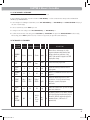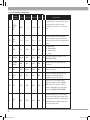
1
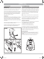
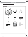
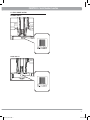
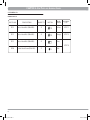
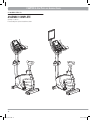
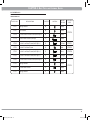
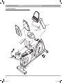
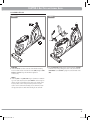
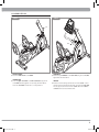
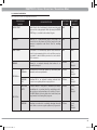
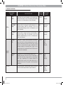
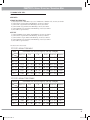
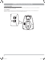
1-SERIES
R1x Recumbent Bike
U1x Upright Bike
R1x_U1x_rev1.1.indd 1
8/6/10 2:50 PM
R1x_U1x_rev1.1.indd 2
8/6/10 2:50 PM
TABLE
OF
CONTENTS
CHAPTER 1: IMPORTANT SAFETY INSTRUCTIONS
1.1
1.2
1.3
Before Getting Started .................................................................................................... 02
Proper Usage ................................................................................................................. 02
Read and Save These Instructions ................................................................................... 02
CHAPTER 2: SETUP
2.1
2.2
2.3
2.4
2.5
2.6
2.7
Getting Started ..............................................................................................................
Choosing a Location .......................................................................................................
Stabilizing the Bike ........................................................................................................
Adjusting the Pedal Strap ...............................................................................................
Adjusting the Seat .........................................................................................................
Self Powered Features.....................................................................................................
Unpacking the Bikes.......................................................................................................
CHAPTER 3: SERIAL NUMBER LOCATION
3.1
3.1
R1x Recumbent .................................................................................................................... 07
U1x Upright .......................................................................................................................... 07
4.1
4.2
4.3
4.4
4.5
4.6
Fasteners U1x .......................................................................................................................... 08
Exploded Diagram U1x ............................................................................................................ 09
Assembly Steps U1x ............................................................................................................... 10
Fasteners R1x .......................................................................................................................... 13
Exploded Diagram R1x ............................................................................................................ 14
Assembly Steps R1x ............................................................................................................... 15
CHAPTER 5: OVERLAY DESCRIPTION / ENGINEERING MODE
5.1
5.2
5.3
5.4
5.5
5.6
Console Display .......................................................................................................................
Workout Parameter Prompts .....................................................................................................
Workout Overviews ...................................................................................................................
Workout Tips ...........................................................................................................................
Workout Setup Steps ...............................................................................................................
Using Fitness Networking .........................................................................................................
CHAPTER 6: MANAGER’S CUSTOM MODE
6.1
List of Manager’s Custom Mode ................................................................................................ 27
7.1
7.2
7.3
7.4
PAGE #
03
03
03
03
04
04
05
CHAPTER 4: BIKE PARTS & ASSEMBLY GUIDES
19
20
21
23
26
CHAPTER 7: MAINTENANCE
Daily Inspection .......................................................................................................................
Daily Maintenance ...................................................................................................................
Monthly Maintenance ..............................................................................................................
Recycling the Battery ..............................................................................................................
29
29
29
29
CHAPTER 8: Product Specifications
30
1
R1x_U1x_rev1.1.indd 1
8/6/10 2:50 PM
CHAPTER 1: Important Safety Instructions
1.1 BEFORE GETTING STARTED
It is the sole responsibility of the purchaser of Matrix Fitness Systems products to instruct all individuals, whether they are the end user or supervising personnel, on proper usage of the equipment.
It is recommended that all users of Matrix Fitness Systems exercise equipment be informed of the following information prior to its use.
1.2 PROPER USAGE
• Do not use the equipment in any way other than designed or intended by
the manufacturer. It is imperative that all Matrix Fitness Systems equipment is used properly to avoid injury.
• Keep hands and feet clear of moving parts at all times to avoid injury.
• Unsupervised children must be kept away from this equipment.
• Do not wear loose clothing while on equipment.
1.3 READ AND SAVE
THESE INSTRUCTIONS
• Do not remove the side covers. Service should only be done by an authorized service technician.
• Close supervision is necessary when used near children, invalids or disabled
people.
• When the bike is in use, young children and pets should be kept at least
three meters / ten feet away.
• Assemble and operate the unit on a solid, level surface. Locate the unit at
least one meter / three feet of clearance from any obstructions, including
walls and furniture.
• Never face backward while using the Matrix bike.
• Use the stationary handlebars to mount or dismount the bike.
• Do not wear any clothing that might catch on any moving parts of this bike.
CAUTION
: If you experience chest pain, nausea, dizziness
or shortness of breath, STOP exercising immediately and consult a physician
before continuing.
CAUTION
: Any changes or modifications to this equipment
could void the product warranty.
This bike is intended for commercial use. To ensure your safety and protect the equipment, read all instructions before operating the Matrix bike.
• Use the bike for its intended purpose as described in this manual. Do not
use attachments that have not been recommended by the manufacturer.
• Never drop or insert any object into any opening of the product. If an object
drops inside, carefully retrieve it while the unit is not in use. If the item
cannot be reached, contact Matrix Fitness or the authorized dealers.
• Never operate the bike if it is not working properly, or if it has been damaged or immersed in water. Return the bike to Matrix Fitness or the
authorized dealers for examination and repair.
• Keep hands and feet clear at all times from moving parts to avoid injury.
• Do not reach into, or underneath the unit, and do not tip the unit on its
side during operation.
• Do not use the Matrix bikes outside, near swimming pools or in areas of
high humidity.
• Do not operate where aerosol (spray) products are being used or when oxygen is being administered.
• Do not use this product in bare feet. Do not wear shoes with heels, leather
soles, cleats or spikes while exercising. 2
R1x_U1x_rev1.1.indd 2
8/6/10 2:50 PM
CHAPTER 2: Setup
2.1 GETTING STARTED
Read the Owner’s Manual before setting up the Matrix bike. Place the unit where it will be used before beginning the setup procedure.
2.2 CHOOSING A LOCATION
The site should be well-lit and well-ventilated. Place the bike on a structurally solid flat surface and kept a few feet from the wall or any equipment. If the
site has a heavy plush carpet, to protect the carpeting and machinery, you should place a rigid plastic base under the unit.
Please do not place the bike in an area of high humidity, such as the vicinity of a steam room, indoor pool, or sauna. Exposure to intensive water vapour
or chlorine could adversely affect the electronics, as well as other parts of the machine. To make exercise a desirable daily activity for you, these two bikes
should be in an attractive setting.
2.3 STABILIZING THE BIKE
After positioning the bike in its intended location, check its stability by attempting to shake it side to side. Shaking or wobbling indicates that your bike needs
to be leveled. Determine which leveler is not resting completely on the floor. Loosen the nut with one hand to allow the leveler to rotate. Rotate the left or right
leveler, and repeat the adjustment as necessary until the bike is stable. Lock the adjustment by tightening the nut against the rear foot support.
U1x
R1x
2.4 ADJUSTING THE PEDAL STRAP
The straps are designed to fit your individual foot size and should be adjusted tight enough to keep your feet from slipping. The pedals include spring-loaded
clips for easy adjustment. To tighten the strap, pull down the open end of the strap. To loosen the strap, push down on the top of the clip and pull the strap up.
Release the clip to lock in place.
U1x
U1x
R1x
R1x
3
R1x_U1x_rev1.1.indd 3
8/6/10 2:50 PM
CHAPTER 2: Setup
2.5 ADJUSTING THE SEAT
2.6 SELF POWERED FEATURES
RECUMBENT BIKE R1x
While seated on the R1x, an optimum position will allow movement through
the bottom of the stroke without locking the knees or shifting in the seat. The
knees should have a slight bend at the point of fullest leg extension.
On the bikes, the user’s pedaling generates the power to initialize and display
information on the monitor. A minimum of 30 RPM (revolutions per minute) is
required to start and maintain enough power to keep the monitor functional. If
the minimum RPM is not maintained, the monitor will begin to shutdown. The
U1x and R1x are able to extend time to display the monitor, at the minimum
RPM not maintained, if the bikes are equipped with the battery. The bike
saves its battery charge by moving into a shutdown mode whenever PEDAL
FASTER appears on the display.
If the seat needs to be adjusted, lift the spring-loaded seat lever on the right
side of the seat to make adjustments. Slide the seat forward or backward to
desired location. Release the spring-loaded seat lever and gently attempt to
rock forward and backward to assure it is locked in place. Check the seat distance again and re-adjust it if necessary.
UPRIGHT BIKE U1x
To determine whether or not the seat requires adjustment, sit on it and place
the foot ankle on the pedals. The knee should bend slightly when the pedal is
at the lowest point of its rotation. It should be possible to pedal without locking the knees or shifting in the seat. The U1x features a vertical ratchet
seat adjustment system, which makes it easy and safe to change the height of
the seat quickly.
To raise the seat, pull the seat upward to the desired height, and let it lock in
place. Test and re-adjust the seat height as necessary.
To lower the seat, first get off the bike. Holding the seat, pull out the seat
post knob. Let the seat slide down to the desired height and release the
seat post knob. Test and re-adjust the seat height as necessary.
U1x
NOTE: The battery is not equipped with the bike for a standard specification.
If your bike equipped with the battery receives inconsistent use, or long time
periods between use, the battery may require recharging. The adapter is an
optional accessory for recharging the unit. To purchase the optional battery
and adapter please contact Matrix Fitness or your local dealer.
SYMPTOMS OF A LOW BATTERY
If the bike has not been used for an extended period of time, the battery may
require recharging. Symptoms of a low battery can include:
• A “LOW BATTERY” message will appear on the monitor
• Backlighting on the LCD display will be disabled
• No one uses the bike for an extended period of time.
If the battery must be recharged, use the optional power adapter charging
unit. The charger should be connected to the bike for a minimum of eight
hours to ensure a thorough charge. If LOW BATTERY still appears on the
display after full charging, the battery could be extinct. Please check with an
authorized service technician for replacing the battery.
REPLACING THE BATTERY
The unit’s battery is built to last for a long time. However, if you feel that the
battery may need replacing, check with an authorized service technician.
CAUTION: The battery stored inside the unit contains hazardous materials to
the environment. Proper disposal of the battery is required by the law.
BATTERY
R1x
C-SAFE
CARDIO
4
R1x_U1x_rev1.1.indd 4
8/6/10 2:50 PM
CHAPTER 2: Setup
2.7 UNPACKING THE BIKES
The bike is carefully inspected before shipment so it should arrive in good operating condition. Matrix Fitness ships the unit in the following pieces:
U1x Upright Bike
(D)
(G)
(A)
Hardware Kit
(E)
A)Main Frame Assembly
B)Console Mast
C)Rear Foot
D)Handlebar Set
E)Accessory Tray
F)Console Set (inside the box)
G)Seat
H)Hardware Kit
(B)
(C)
(H)
(F)
5
R1x_U1x_rev1.1.indd 5
8/6/10 2:50 PM
CHAPTER 2: Setup
2.7 UNPACKING THE BIKES
The bike is carefully inspected before shipment so it should arrive in good operating condition. Matrix Fitness ships the unit in the following pieces:
R1x Recumbent Bike
(D)
(E)
(I)
(J)
(K)
(F)
Hardware Kit
(L)
(A)
(B)
(C)
(G)
A)Main Frame Assembly
B)Front Handlebar Set
C)Console Mast
D)Console Set
E)Seat
F)Seat Back
G)Seat Back Cover
H)Accessory Tray
I) Rear Handlebar Set
J) Rear Foot
K)Seat Frame
L)Hardware Kit
(H)
6
R1x_U1x_rev1.1.indd 6
8/6/10 2:50 PM
CHAPTER 3: Serial Number Location
3.1 SERIAL NUMBER LOCATION
RECUMBENT BIKE R1x
UPRIGHT BIKE U1x
7
R1x_U1x_rev1.1.indd 7
8/6/10 2:50 PM
CHAPTER 4: Bike Parts
and
Assembly Guides
4.1 FASTNERS U1x
UPRIGHT BIKE U1x
PARTS NO.
DESCRIPTION
QUANTITY
SKETCH
COLOR
OF BAG
ASSEMBLY
STEP
Z01
Button Head Bolt (M8×20L)
4
Yellow
STEP 1
Z01
Button Head Bolt (M8×20L)
4
Orange
STEP 3
Z01
Button Head Bolt (M8×20L)
4
Blue
STEP 4
Z08
Socket Head Screw (M5×25L)
2
Pink
8
R1x_U1x_rev1.1.indd 8
8/6/10 2:50 PM
CHAPTER 4: Bike Parts
and
Assembly Guides
4.2 EXPLODED DIAGRAM U1x
4
Z01 x 2
N22 x 4
AC1
Z01 x 2
Z01 x 4
Z01 x 4
Z08 x 2
9
R1x_U1x_rev1.1.indd 9
8/6/10 2:50 PM
CHAPTER 4: Bike Parts
and
Assembly Guides
4.3 ASSEMBLY STEPS U1x
STEP 1
STEP 2
Z01
Z01
REAR FOOT
1) Install the rear foot in position at the rear of the bike with the mating
holes in the frame bracket. Insert the four bolts (Z01) through the frame
bracket and rear foot. Using a #6 Allen Wrench, tighten the screws completely.
1) Remove the nuts from the bottom of the seat. Attach the seat to the seat
post with the nuts you just removed. Tighten them with an
Open Wrench.
PEDALS
1) Install the pedals on the pedal cranks using an Open Wrench. The Matrix
logo of the pedal strap must point upward.
NOTE: Be careful to align the threads correctly to avoid damage. A little
grease on the threads should help the pedals to screw in easily and correctly. Turn the left pedal spindle counterclockwise when threading into
the crank arm, and turn the right pedal
10
R1x_U1x_rev1.1.indd 10
8/6/10 2:50 PM
CHAPTER 4: Bike Parts
and
Assembly Guides
4.3 ASSEMBLY STEPS U1x
STEP 3
STEP 4
Z01
Z01
Z08
Z08
Z01
Z01
1) Secure the upper console mast to the lower console mast using four bolts
(Z01). Alternately tighten each bolt using a #6 Allen Wrench. Check the
console mast to make sure it is securely fastened.
HANDLEBAR SET
1) Feed the heart rate wires of the handlebar through the small hole located
in the front of the console mast. Pull these wires up through the hole at
the top of the console mast. Attach the handlebar to the console mast
using four bolts (Z01). Tighten with a #6 Allen Wrench.
CONSOLE
1) Remove the four mounting bolts from the back of the console with a Phillips Screwdriver. Plug in the wire harness and the two heart rate wires to
the back of the console. Attach the console to the console mast with the
four bolts removed earlier in this step.
ACCESSORY TRAY
1) Attach the accessory tray to the console mast using two screws (Z08).
Tighten them with a Phillips Screwdriver.
11
R1x_U1x_rev1.1.indd 11
8/6/10 2:50 PM
CHAPTER 4: Bike Parts
and
Assembly Guides
4.3 ASSEMBLY STEPS U1x
ASSEMBLY COMPLETE
Assembly is complete.
Final assembly and optional entertainment shown.
12
R1x_U1x_rev1.1.indd 12
8/6/10 2:50 PM
CHAPTER 4: Bike Parts
and
Assembly Guides
4.4 FASTNERS R1x
UPRIGHT BIKE R1x
PARTS NO.
DESCRIPTION
QUANTITY
SKETCH
COLOR
OF BAG
ASSEMBLY
STEP
Z01
Spring Washer
8
White
Z02
Arc Washer
8
White
Z03
Socket Button Head Screw (with Nyloc)
8
White
Z13
Button Head Screw (Phillips)
2
White
Z04
Socket Low Head Screw (with Nyloc)
4
Yellow
STEP 1
Z05
Socket Flat Head Screw
3
Red
STEP 3
Z04
Socket Low Head Screw (with Nyloc)
4
Blue
STEP 6
Z04
Socket Low Head Screw (with Nyloc)
4
Orange
STEP 5
Z09
Socket Button Head Screw (with Nyloc)
4
Black
Z10
Spring Wahser
4
Black
Z11
Socket Head Screw
2
Black
Z12
Spring Washer
2
Black
STEP 4
STEP 2
13
R1x_U1x_rev1.1.indd 13
8/6/10 2:50 PM
CHAPTER 4: Bike Parts
and
Assembly Guides
4.5 EXPLODED DIAGRAM R1x
Z04
Z04
Z04
Z02
Z01
Z03
Z09
Z10
Z02
Z01
Z13
Z11
Z12
Z03
Z05
Z04
14
R1x_U1x_rev1.1.indd 14
8/6/10 2:50 PM
CHAPTER 4: Bike Parts
and
Assembly Guides
4.6 ASSEMBLY STEPS R1x
STEP 1
STEP 2
L R
L R
Z05
Z05
Z04
Z04
REAR FOOT
1) Install the rear foot in position at the rear of the bike with the mating
holes in the frame bracket. Insert the four screws (Z04) through the frame
bracket and rear foot. Using a #5 Allen Wrench tighten the
screws securely.
1) Pull the heart rate wire through the hole in the bottom of the seat frame,
and make sure the wire get through the tunnel of the plate. Mount the
seat handlebars to the seat frame by using three socket-flat-head screws
(Z05).
PEDALS
1) Install the pedals on the pedal cranks using an Open Wrench. The Matrix
logo on the pedal strap must point upward. NOTE: Be careful to align the
threads correctly to avoid damage. A little grease on the threads should
help the pedals to screw in easily and correctly. Turn the left pedal
spindle counter clockwise when threading into the crank arm, and turn
the right pedal spindle clockwise when threading into the crank arm.
15
R1x_U1x_rev1.1.indd 15
8/6/10 2:50 PM
CHAPTER 4: Bike Parts
and
Assembly Guides
4.6 ASSEMBLY STEPS R1x
STEP 3
STEP 4
Z09
Z10
Z09
Z10
Z02
Z01
Z03
Z12
Z13
Z13
Z02
Z01
Z03
Z11
Z12
Z11
Z02
Z01
Z02
Z01
Z03
Z03
1) Install the seat rail on the seat adjustment bracket using the four washers
(Z10) and screws (Z09). Tighten them with an #5 Allen Wrench.
2) Connect the wire harness from the seat handlebar to the wire harness
coming from the seat frame.
3) Slide the seat adjustment handle between the teeth of the seat adjustment
bracket.
ACCESSORY
1) Secure the accessory tray to the seat handlebar with two button-head
screws (Z13). Be careful when inserting the bolts to clear the wires
inside the handlebar to prevent damage. Tighten with a Philips screwdriver.
SEAT AND SEATBACK
1) Mount the seat to the seat frame with four arc washers (Z02), spring
washers (Z01) and socket button-head screws (Z03). Tighten with a #5
Allen Wrench. Mount the seatback to the seat frame with four arc washers
(Z02), spring washers (Z01) and socket button-head screws (Z03). Tighten
with a #5 Allen Wrench.
16
R1x_U1x_rev1.1.indd 16
8/6/10 2:50 PM
4.6 ASSEMBLY STEPS R1x
STEP 5
STEP 6
Z04
Z04
Z04
Z04
Z04
SEATBACK COVER
1) Attach the seatback cover to the seatback.
CONSOLE MAST
1) Secure the upper console mast to the lower console mast using the four
screws (Z04). Alternately tighten each bolt using a #5 Allen Wrench.
Check the console mast to make sure it is securely fastened.
Z04
HANDLEBAR
1) Mount the upper handlebars to the console mast using four screws (Z04).
Tighten with a #5 Allen Wrench
CONSOLE
1) Remove the four mounting bolts from the back of the console. Connect
the wire harnesses and heart rate wires that come from the console mast
into the plugs located in the back of the console. Attach the console to
the mast with the four bolts removed earlier.
17
R1x_U1x_rev1.1.indd 17
8/6/10 2:50 PM
CHAPTER 4: Bike Parts
and
Assembly Guides
4.6 ASSEMBLY STEPS R1x
ASSEMBLY COMPLETE
Assembly is complete.
Final assembly and optional entertainment shown.
18
R1x_U1x_rev1.1.indd 18
8/6/10 2:51 PM
CHAPTER 5: Overlay Description / Engineering Mode
5.1 CONSOLE DISPLAY
D
A
B
C
E
G
F
H
A) WORKOUT PROFILE WINDOW:
During a workout, this window displays shapes, made of triangle columns of lights, which represent the levels of intensity in a workout-in-progress. The
height of the furthest column is proportional to the current level of the intensity. Information will cycle every 30 seconds.
B) INSTURCTION CENTER:
This window displays step-by-step instructions for setting up a workout.
C) INFORMATIONAL DISPLAY: During a workout, three sets of numbers, including Speed, Time and Distance, display statistics about the progress of the workout.
D) PROGRAM PLUS™ KEYS
Press the key to select one of the workouts. The program key with a symbol of plus “+” represents additional workout options. Press this key repeatedly for
similar workout options.
E) LEVEL ARROW KEYS
During a workout, pressing the UP or DOWN arrow can adjust intensity levels.
F) RIGHT / LEFT ARROW KEYS
A pair of RIGHT and LEFT arrows is located on the side of SELECT. Use arrows, when setting up a workout, to change workout parameters displayed on
the LCD console, such as length of workout, weight, age, heart rate, and intensity level. In addition, the pair of RIGHT and LEFT arrows is corresponding
to the arrows in the LCD display.
G) QUICK START
Press QUICK START to begin your workout immediately, without having to select a workout program.
H) RESET
PAUSE: If you need to PAUSE your program during a workout, stop pedaling. It will PAUSE your program for 30 seconds. Pressing START will return you
to your workout. NOTE: Pause time is only available for ellipticals equipped with the battery.
RESET: If you need to RESET the console during your workout, you can do so by holding down the RESET button for three seconds, or until the
display resets.
19
R1x_U1x_rev1.1.indd 19
8/6/10 2:51 PM
CHAPTER 5: Overlay Description / Engineering Mode
5.2 WORKOUT PARAMETER PROMPTS
This section lists the default value and value range of workout parameters appeared in the PROMPT AREA, located in the bottom of WORKOUT
PROFILE WINDOW. Before an exercise session, each parameter prompt will appear here depending on different programs.
PROMPT
DEFAULT
MINIMUM
MAXIMUM
UNIT
minute
TIME
20
5
99
LEVEL
1
1
20
WEIGHT
68 / 150
34 / 75
182 / 400
kg / lbs
AGE
30
10
99
years old
DISTANCE
5/3
1/1
80 / 50
km / mile
CALORIES
500
50
5000
cal.
WATTS
150
50
350
watt
Heart Rate
n/a
52
200
beat
GENDER
MALE
MALE
FEMALE
NOTE: The workout time is a “countdown” display according to the default time or the maximum time that a user inputs. When the workout time is
inputted as “0”, the time will count up from a zero to the maximum time.
20
R1x_U1x_rev1.1.indd 20
8/6/10 2:51 PM
CHAPTER 5: Overlay Description / Engineering Mode
5.3 WORKOUT OVERVIEWS
This chart lists the bike’s pre-programmed workouts.
PROGRAM
NAME
DESCRIPTION
DEFAULT PROMPT
TIME
INPUT
PROGRAM
NAME
QUICK START
Quick Start is the fastest way to begin exercising and
bypasses the setup prompts. After pressing the QUICK
START key, a constant-level workout begins.
N/A
N/A
TIME
GOAL
WARM UP
Warm-up is a low-intensity phase that brings the
heart rate into the lower end of the target zone and
increases respiration and blood flow to working
muscles.
N/A
Time
DIST
GOAL
COOL DOWN
Cool-down is a low-intensity phase that allows the
body to begin removing lactic acid, and other exercise
by-products, which build up in muscles and contribute to soreness.
N/A
Time
MANUAL
Manual is a constant intensity level unless it is
manually changed.
20 min
Time,
Weight
HILL
INTERVAL
Hill Interval is an efficient workout by alternating work
intervals and recovery intervals.
20 min
Level,
Time,
Weight
RANDOM
HILL
Random Hill is an interval training workout that
occurs in no regular pattern or progression.
20 min
Time,
Weight
CONSTANT
WATTS
Constant Watts is designed to maintain your watts
expenditure at a constant level by controlling pedaling resistance and prompting you to pedal at a specified RPM. Watts level may vary above and below your
target watts level during this program.
20 min
Watts,
Time,
Weight
RANDOM
Random is a workout of constantly changing intensity
levels that occur in no regular pattern or progression.
20 min
Level,
Time,
Weight
GOAL+
INTERVAL+
MULTI FX+
CALO
GOAL
TARG
HR
HEART
RATE+
FIT TEST
21
R1x_U1x_rev1.1.indd 21
8/6/10 2:51 PM
WEIG
LOSS
CHAPTER 5: Overlay Description / Engineering Mode
5.3 WORKOUT OVERVIEWS
PT
UT
PROGRAM
NAME
GOAL+
HEART
RATE+
FIT TEST
DESCRIPTION
DEFAULT PROMPT
TIME
INPUT
TIME
GOAL
Time Goal sets exercise duration as the workout goal.
Once the objective is met, the workout automatically
goes into a cool-down phase and ends afterward.
20 min
Time,
Weight
DISTANCE
GOAL
Distance Goal is designed to build endurance in a
certain distance. Once the objective is met, the
workout automatically goes into a cool-down phase, and
ends afterward.
N/A
Distance,
Weight
CALORIES
GOAL
Calories Goal is designed to burn a certain number of
selected calories. Once the objective is met, the
workout automatically goes into a cool-down phase
and ends afterward.
N/A
Calories,
Weight
TARGET
HR
Target HR is a higher intensity workout for maintaining a heart rate to achieve maximum exercise results.
The user must wear a heart rate chest strip, or keep
hands on contact heart rate grips continuously. The
program adjusts the intensity level, based on the
actual heart rate, to maintain the rate at 80 percent of
the theoretical maximum.
20 min
Age,
HR,
Time,
Weight
WEIGHT
LOSS
Weight Loss is a low-intensity workout for
burning the body’s fat reserves. The user must wear a
heart rate chest strip, or keep hands on contact heart
rate grips continuously. The program adjusts the
intensity level, based on the actual heart rate, to
maintain the rate at 65 percent of the theoretical
maximum.
20 min
Age,
HR,
Time,
Weight
Fit Test measures cardiovascular fitness and can be
used to monitor improvements in your endurance.
12 min
Gender,
Age,
Level,
Weight
22
R1x_U1x_rev1.1.indd 22
8/6/10 2:51 PM
CHAPTER 5: Overlay Description / Engineering Mode
5.4 WORKOUT TIPS
1) Matrix Fitness strongly recommends seeing your physician for a complete physical examination before beginning any fitness program. Know your physician-recommended heart rate target zone. If, at any time while exercising, you experiences faintness, dizziness, pain, or shortness of breathe, you must
stop immediately.
2) To mount the bike, grasp the front stationary handlebars and place your feet on the pedals. When you are comfortably situated, begin pedaling. To dismount
the bike, stop pedaling, grasp the front stationary handlebars and get off the unit.
3) It is highly recommended that you always incorporate the warm-up and cool-down period into your workout. Warm-up brings the heart rate into the lower
end of the target zone and increases respiration and blood flow to working muscles. Cool-down takes time for a user’s heart rate to return to a resting state
after vigorous exercise and reduces the amount of lactic acid in muscle tissue.
5.5 WORKOUT SETUP STEPS
Different bike workouts require different setup procedures. This section provides details for settling up any workout program.
1) Begin to pedal the bike.
2) Use the PROGRAM PLUS™ KEYS to enter the program, or use RIGHT / LEFT ARROW keys to scroll to desired program. The program name is displayed in
the PROMPT AREA.
3) Use the RIGHT / LEFT ARROW keys to scroll to desired parameter values displayed in the PROMPT AREA.
4) Press the SELECT key to confirm each selection. Follow the steps to set up each workout.
NOTE: The PROGRAM PLUS™ KEYS with a symbol of plus “+” have couple of similar workout options included. Press the key repeatedly to select the desired program. Or, press the program
key once and use RIGHT / LEFT ARROW keys to scroll to the desired program.
QUICK START
Press the “QUICK START” key and the WORKOUT PROFILE WINDOW will display “3, 2, 1, GO!” The workout begins at the default intensity level, and the
workout time counts up from “0” to the maximum workout time.
WARM UP
1) Press the “WARM-UP” key to enter the program.
2) “SELECT TIME” using the RIGHT / LEFT ARROW keys, and then press SELECT.
3) Press START to begin a warm-up.
COOL DOWN
1) Press the “COOL-DOWN” key to enter the program.
2) “SELECT TIME” using the RIGHT / LEFT ARROW keys, and then press SELECT.
3) Press START to begin a cool-down.
MANUAL
1) Press the “MANUAL” key to enter the program.
2) “SELECT TIME” using the RIGHT / LEFT ARROW keys, and then press SELECT.
3) “SELECT WEIGHT” using the RIGHT / LEFT ARROW keys, and then press SELECT.
4) Press START to begin the workout.
23
R1x_U1x_rev1.1.indd 23
8/6/10 2:51 PM
CHAPTER 5: Overlay Description / Engineering Mode
5.5 WORKOUT SETUP STEPS
INTERVAL +
A)HILL INTERVAL
1) Repeatedly Press the “INTERVAL+” key to select “HILL INTERVAL”, and then press SELECT.
2) “SELECT LEVEL” using the RIGHT / LEFT ARROW keys, and then press SELECT.
3) “SELECT TIME” using the RIGHT / LEFT ARROW keys, and then press SELECT.
4) “SELECT WEIGHT” using the RIGHT / LEFT ARROW keys, and then press SELECT.
5) Press START to begin the workout.
B)RANDOM HILL
1)
2)
3)
4)
Repeatedly Press the “INTERVAL+” key to select “RANDOM HILL”, and then press SELECT.
“SELECT TIME” using the RIGHT / LEFT ARROW keys, and then press SELECT.
“SELECT WEIGHT” using the RIGHT / LEFT ARROW keys, and then press SELECT.
Press START to begin the workout.
MULTI FX +
A)CONSTANT WATTS
1)
2)
3)
4)
5)
Repeatedly Press the “MULTI FX+” key to select “CONSTANT WATTS”, and then press SELECT.
“SELECT WATTS” using the RIGHT / LEFT ARROW keys, and then press SELECT.
“SELECT TIME” using the RIGHT / LEFT ARROW keys, and then press SELECT.
“SELECT WEIGHT” using the RIGHT / LEFT ARROW keys, and then press SELECT.
Press START to begin the workout.
B)RANDOM
1) Repeatedly Press the “MULTI FX+” key to select “RANDOM ”, and then press SELECT.
2) “SELECT LEVEL” using the RIGHT / LEFT ARROW keys, and then press SELECT.
3) “SELECT TIME” using the RIGHT / LEFT ARROW keys, and then press SELECT.
4) “SELECT WEIGHT” using the RIGHT / LEFT ARROW keys, and then press SELECT.
5) Press START to begin the workout.
GOAL +
A)TIME GOAL
1) 1)
2) 2)
3) 3)
4) 4)
Repeatedly Press the “GOAL+” key to select “TIME GOAL”, and then press SELECT.
“SELECT TIME” using the RIGHT / LEFT ARROW keys, and then press SELECT.
“SELECT WEIGHT” using the RIGHT / LEFT ARROW keys, and then press SELECT.
Press START to begin the workout.
B)DISTANCE GOAL
1) 1)
2) 2)
3) 3)
4) 4)
Repeatedly Press the “GOAL+” key to select “DISTANCE GOAL”, and then press SELECT.
“SELECT DISTANCE” using the RIGHT / LEFT ARROW keys, and then press SELECT.
“SELECT WEIGHT” using the RIGHT / LEFT ARROW keys, and then press SELECT.
Press START to begin the workout.
C)CALORIES GOAL
1) 1) Repeatedly Press the “GOAL+” key to select “CALORIES GOAL”, and then press SELECT.
2) 2) “SELECT CALORIES” using the RIGHT / LEFT ARROW keys, and then press SELECT.
3) 3) “SELECT WEIGHT” using the RIGHT / LEFT ARROW keys, and then press SELECT.
4) 4) Press START to begin the workout.
24
R1x_U1x_rev1.1.indd 24
8/6/10 2:51 PM
CHAPTER 5: Overlay Description / Engineering Mode
5.5 WORKOUT SETUP STEPS
HEART RATE +
A)TARGET HR / WEIGHT LOSS
1)
2)
3)
4)
5)
6)
Repeatedly Press the “HEART RATE+” key to select “TARGET HR” or “WEIGHT LOSS”, and then press SELECT
“SELECT AGE” using the RIGHT / LEFT ARROW keys, and then press SELECT.
“SELECT HR” using the RIGHT / LEFT ARROW keys, and then press SELECT.
“SELECT TIME” using the RIGHT / LEFT ARROW keys, and then press SELECT.
“SELECT WEIGHT” using the RIGHT / LEFT ARROW keys, and then press SELECT.
Press START to begin the workout.
B)FIT TEST
1)
2)
3)
4)
5)
“SELECT GENDER” using the RIGHT / LEFT ARROW keys, and then press SELECT.
“SELECT AGE” using the RIGHT / LEFT ARROW keys, and then press SELECT.
“SELECT LEVEL” using the RIGHT / LEFT ARROW keys, and then press SELECT.
“SELECT WEIGHT” using the RIGHT / LEFT ARROW keys, and then press SELECT.
Press START to begin the workout.
The tables below list fit test results:
FIT TEST’S RESULT FOR MALE
Male
Age
Rating
Estimated VO2 Max (ml/kg/min) Per Age Category
Very Poor
Poor
Fair
Good
Excellent
Superior
15 – 19
< 35.0
35.0 – 38.3 38.4 – 45.1 45.2 – 50.9 51.0 – 55.9
> 55.9
20 – 29
< 33.0
33.0 – 36.4 36.5 – 42.4 42.5 – 46.4 46.5 – 52.4
> 52.4
30 – 39
< 31.5
31.5 – 35.4 35.5 – 40.9 41.0 – 44.9 45.0 – 49.4
> 49.4
40 – 49
< 30.2
30.2 – 33.5 33.6 – 38.9 39.0 – 43.7 43.8 – 48.0
> 48.0
50 – 59
< 26.1
26.1 – 30.9 31.0 – 35.7 35.8 – 40.9 41.0 – 45.3
> 45.3
60 +
< 20.5
20.5 – 26.0 26.1 – 32.2 32.3 – 36.4 36.5 – 44.2
> 44.2
FIT TEST’S RESULT FOR FEMALE
Female
Age
Rating
Estimated VO2 Max (ml/kg/min) Per Age Category
Very Poor
Poor
Fair
Good
Excellent
Superior
15 – 19
<25.0
25.0 – 30.9 31.0 – 34.9 35.0 – 38.9 39.0 - 41.9
>41.9
20 – 29
<23.6
23.6 – 28.9 29.0 – 32.9 33.0 – 36.9 37.0 - 41.0
>41.0
30 – 39
<22.8
22.8 – 26.9 27.0 – 31.4 31.5 – 35.6 35.7 - 40.0
>40.0
40 – 49
<21.0
21.0 – 24.4 24.5 – 28.9 29.0 – 32.8 32.9 - 36.9
>36.9
50 – 59
<20.2
20.2 – 22.7 22.8 – 26.9 27.0 – 31.4 31.5 - 35.7
>35.7
60 +
<17.5
17.5 – 20.1 20.2 – 24.4 24.5 - 30.2 30.3 - 31.4
>31.4
25
R1x_U1x_rev1.1.indd 25
8/6/10 2:51 PM
CHAPTER 5: Overlay Description / Engineering Mode
5.6 USING FITNESS NETWORK
The two RJ45 networking ports are equipped in both the upright and recumbent bike. These ports allow the bike to be connected to a fitness entertainment system and/or a fitness network, such as FitLinxx®.
C-SAFE / CARDIO PORT
The ports are located on the back of the console. The C-SAFE port enables the bike to upload user workout statistics to a fitness network database. The
CARDIO port is compatible to entertainment protocol such as Cardio Theater® or BroadcastVision™.
C-SAFE
CARDIO
C-SAFE
CARDIO
26
R1x_U1x_rev1.1.indd 26
8/6/10 2:51 PM
CHAPTER 6: Manager’s Custom Mode
6.1 LIST OF MANAGER’S CUSTOM MODE
The Manager’s Custom Mode allow the club owner to customize the bike for the club.
To enter the Manager’s Custom Mode, press and hold down the “LEVEL ARROW keys“ . Continue to hold down these two keys until the INSTRUCTION
CENTER displays “MANAGER MENU”.
1. To scroll through the list of Manager’s Custom Mode, use the “LEFT / RIGHT ARROW keys”, or “LEVEL ARROW keys”. The INSTRUCTION CENTER will display, in
turn, each of custom settings.
2. To select a custom mode, press the SELECT key to enter.
3. To change the value of the setting, use the “LEFT / RIGHT ARROW keys”, or “LEVEL ARROW keys”.z
4. To confirm and save the value of the setting, press the QUICK START key. “SETTING SAVED” will appear in the INSTRUCTION CENTER. To exit the setting
without saving, press the RESET key within 5 seconds, or if there is no key pressed, the system will resume automatically.
LIST OF MANAGER’S CUSTOM MODES:
CUSTOM
SETTING
DEFAULT MINIMUM MAXIMUM
UNIT
STEP
DESCRIPTION
P0
MAXIMUM
TIME
99 min
20 min
99 min
minute
1
Enable fitness club managers to set the
program maximum workout duration limits
during peak and non-peak hours of club
traffic. Active variable displayed in the TIME
display after change.
P1
DEFAULT
TIME
20 min
5 min
max.
time
minute
1
Control the default program time.
P2
DEFAULT
LEVEL
1
1
10
n/a
1
Control the starting resistance level for
all programs.
P3
MAXIMUM
LEVEL
20
1
20
n/a
1
Enable to set maximum resistance level for all
programs.
P4
DEFAULT
WEIGHT
68kg /
150lbs
34kg /
75lbs
182kg /
400lbs
kg/lbs
1
Control the default weight used in calorie
calculations. Set to default unit change
(kilograms or pounds). Displayed in
native units.
P5
DEFAULT
AGE
30
10
99
age
1
Control the default users age used in target
heart rate calculations.
P6
ACCUMULATED
DISTANCE
N/A
0
104,000
km /
65,000
mile
km /
mile
N/A
Accumulated distance is not editable, but only
for display. Displayed in native units (miles or
kilometers). After the equipment reaches the
maximum distance, it will reset to "0"
automatically.
27
R1x_U1x_rev1.1.indd 27
8/6/10 2:51 PM
CHAPTER 6: Manager’s Custom Mode
6.1 LIST OF MANAGER’S CUSTOM MODE
CUSTOM
SETTING
P7
ACCUMULATED
TIME
P8
PAUSE
TIME
P9
MODEL
DEFAULT MINIMUM MAXIMUM
N/A
30 sec
0
30 sec
65,000 hrs
180 sec
UNIT
hour
second
EL
N/A
N/A
N/A
STEP
N/A
1
DESCRIPTION
Accumulated time is not editable, but only for
display. After the machine reaches the
maximum time, it will reset to "0" automatically.
This is the maximum time during which a
workout can remain in pause mode. Restrictions exist for the machine not equipped with a
battery.
N/A
CB - Upright Bike
RB - Recumbent Bike
EL – Elliptical Trainer
ST - Stepper
P10
LANGUAGE
English
N/A
N/A
N/A
N/A
The native language prompts in the
INSTRUCTION CENTER.
P11
SOFTWARE
VERSION
N/A
N/A
N/A
N/A
N/A
Software version is not editable, but only
for display.
P12
UNITS
English
English
Metric
N/A
N/A
The measurement unit prompts for weight,
distance, and speed.
P13
ERROR
LOG
N/A
N/A
N/A
N/A
N/A
Error log is not editable, but only for display.
Holding the Left and Right Arrow keys
simultaneously to erase the error log.
P14
P15
METS
RESET
ALL
OFF
N/A
ON
N/A
OFF
N/A
N/A
N/A
N/A
N/A
If this option is "ON", the METs prompt
becomes an individual display in PROMPT
AREA. If "OFF", there will be an alternate
prompt in RPM and METs at the lower-right
corner of the WORKOUT PROFILE WINDOW.
The function would clear all custom settings
had stored on the unit and all settings return
to manufacturer default value. Holding the Left
and Right Arrow keys simultaneously to clear
all custom settings values.
28
R1x_U1x_rev1.1.indd 28
8/6/10 2:51 PM
CHAPTER 7: Maintenance
MAINTENANCE
The Matrix R1x/U1x are built for commercial use 12 hours a day and seven days a week. However, as a club manager or owner, you are responsible for cleaning and maintaining the unit’s integrity. If you fail to maintain the bike as described below, it could affect or void the Matrix limited warranty.
NOTE: Safety of the equipment can be maintained only if the equipment is examined regularly for damage or wear. Keep the equipment out of use until
defective parts are repaired or replaced. Pay special attention to parts that are subject to wear, such as display console, console mounting screws, handrails,
link arms, pedal arms and pedals.
7.1 DAILY INSPECTION
Look and listen for loose fasteners, unusual noises, and any other indications that the
equipment may be in need of service. If you notice any of these, obtain service.
7.2 DAILY MAINTENANCE
Matrix Fitness recommends the R1x/U1x be cleaned before and after each workout. The following daily maintenance tips will keep your unit operating at
peak performance:
1) Use a damp, soft cloth with water or mild liquid detergent to clean all exposed surfaces. DO NOT use ammonia, chlorine, or acid-based cleaners.
2) Keep the display console free of fingerprints and salt build-up caused by sweat.
3) Frequently vacuum the floor underneath the unit to prevent the accumulation of dust and dirt, which can affect the smooth operation of the unit.
7.3 MONTHLY MAINTENANCE
Perform the following services each month, or as needed:
1) Check that the console, handrails, link arms, pedal arms and pedals are secure.
7.4 RECYCLING THE BATTERY
When the Matrix bike is about to be discarded at the end of its useful life, the rechargeable battery must first be removed and recycled. If the bike is being
equipped with the battery. To access the battery, unscrew the cover on the back of the console. To remove the battery, disconnect the cable.
29
R1x_U1x_rev1.1.indd 29
8/6/10 2:51 PM
CHAPTER 8: Product Specifications
U1x
R1x
CONSOLE
Workout Profile Window – 7” blue backlit graphic LCD display
Display Screen
Instruction Center – 14-character red LED alphanumeric display
Informational Display – 3 numeric 7-segment display (3 sets)
Display Readout
Time, Distance, Calories, Speed, Level, Watts, METS, Heart Rate, Profile
Programs
Manual, Interval+(Hill Interval, Random Hill), Goal+(Time Goal, Distance Goal,
Calories Goal), Multi FX+(Constant Watts, Random), Heart Rate+(Target HR, Weight
Loss), Fit Test, Warm Up, Cool Down
On-the-fly Program Change
Yes
Telemetric Receiver
Yes
Contact HR Sensors
Yes
Program Quick Keys
Yes
One-Touch Quick Start
Yes
Pause Time
30 seconds
Language Options
English, Italian, German, Spanish, French, Dutch, Portuguese, Japanese
TECHNICAL DATA
Resistance Technology
JID™ hybrid generator
Resistance Levels
20
Drive System
One stage belt-driven
Seat Adjustments
12 positions
25 positions
Dimension (L x W x H)
103 x 65 x 131 cm / 41” x 26” x 52”
167 x 68 x 128 cm / 66” x 27” x 50”
Product Weight
63.5 kg / 140 lbs
85 kg / 188 lbs
Max User Weight
182 kg / 400 lbs
Power Requirement
Self-powered
SPECIAL FEATURES
Step-thru Design
N/A
Yes
Handlebar Design
Ergonomic elbow rests design with
Front stationary handlebars and racing
integrated contact HR handgrips
handlebars integrated contact HR handgrips
Pedals
Extra large pedals with ratcheted strap adjustments
Seat Design
Contoured shape seat
Ratcheting Seat Adjustment
Yes
N/A
Remote Operation Keys
N/A
Yes
Integrated Reading Rack
Yes
Accessory Tray
Yes
Comfort seat and stylish seat back
ENTERTAINMENT SOLUTIONS
Matrix ® LCD TV Mount
Yes
Networking Capabilities
Yes
*Product specifications are subject to change without notice.
30
R1x_U1x_rev1.1.indd 30
8/6/10 2:51 PM
R1x_U1x_rev1.1.indd 31
8/6/10 2:51 PM
M AT R I X F I T N ESS | 1 60 0 L A N D M A R K D R I V E COT TAG E G ROV E W I 53 527 USA
To l l Fre e 8 6 6 . 693.4 8 63 m a t r i x f i t n e ss . co m Fa x 60 8 . 8 3 9. 8 687
PA RT # 0 0 0 0 090 1 62
REV. 1.1
R1x_U1x_rev1.1.indd 32
8/6/10 2:51 PM