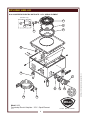
1
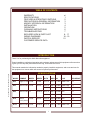
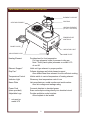
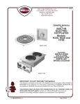
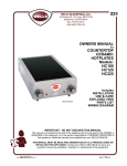
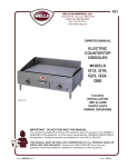
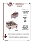
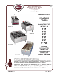
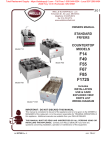
221
WELLS BLOOMFIELD, LLC
10 Sunnen Dr., St. Louis, MO 63143
telephone: 314-678-6314
fax: 314-781-2714
www.wells-mfg.com
OWNERS MANUAL
for
COUNTER TOP
ELECTRIC
HOTPLATES
Models:
H33
H63
H65
H70
H115
Includes
INSTALLATION
USE & CARE
EXPLODED VIEW
PARTS LIST
WIRING DIAGRAM
Model H70
IMPORTANT: DO NOT DISCARD THIS MANUAL
This manual is considered to be part of the appliance and is to be given to the OWNER or
MANAGER of the restaurant, or to the person responsible for TRAINING OPERATORS of
this appliance. Additional manuals are available from your WELLS DEALER.
THIS MANUAL MUST BE READ AND UNDERSTOOD BY ALL PERSONS USING OR
INSTALLING THIS APPLIANCE. Contact your WELLS DEALER if you have any
questions concerning installation, operation or maintenance of this equipment.
p/n 2M-303733 Rev. D
M221
091218
LIMITED WARRANTY STATEMENT
Unless otherwise specified, all commercial cooking
equipment manufactured by WELLS BLOOMFIELD, LLC is
warranted against defects in materials and workmanship for
a period of one year from the date of original installation or
18 months from the date of shipment from our factory,
whichever comes first, and is for the benefit of the original
purchaser only.
THIS WARRANTY IS THE COMPLETE AND ONLY
WARRANTY, EXPRESSED OR IMPLIED IN LAW OR IN
FACT, INCLUDING BUT NOT LIMITED TO, WARRANTIES
OF MERCHANTABILITY OR FITNESS FOR ANY
PARTICULAR PURPOSE, AND/OR FOR DIRECT,
INDIRECT OR CONSEQUENTIAL DAMAGES IN
CONNECTION WITH WELLS BLOOMFIELD PRODUCTS.
This warranty is void if it is determined that, upon inspection
by an authorized service agency, the equipment has been
modified, misused, misapplied, improperly installed, or
damaged in transit or by fire, flood or act of God. It also
does not apply if the serial nameplate has been removed, or
if service is performed by unauthorized personnel. The
prices charged by Wells Bloomfield for its products are
based upon the limitations in this warranty. Seller’s
obligation under this warranty is limited to the repair of
defects without charge by a Wells Bloomfield factory
authorized service agency or one of its sub-service
agencies. This service will be provided on customer’s
premises for non-portable models. Portable models (a
device with a cord and plug) must be taken or shipped to
the closest authorized service agency, transportation
charges prepaid, for service. In addition to restrictions
contained in this warranty, specific limitations are shown in
the Service Policy and Procedure Guide. Wells Bloomfield
authorized service agencies are located in principal cities.
This warranty is valid in the United States and Canada and
void elsewhere. Please consult your classified telephone
directory, your foodservice equipment dealer or contact:
Wells Bloomfield, LLC
10 Sunnen Dr., St. Louis MO 63143 USA
phone (314) 678-6314 or fax (314) 781-2714
for information and other details concerning warranty.
SERVICE POLICY AND PROCEDURE GUIDE and ADDITIONAL WARRANTY EXCLUSIONS
1.
2.
3.
4.
5.
6.
cleaning schedules, are customer responsibility. Those
miscellaneous adjustments noted are customer
responsibility. Proper attention to preventative
maintenance and scheduled maintenance procedures
will prolong the life of the appliance.
7. Travel mileage is limited to sixty (60) miles from an
Authorized Service Agency or one of its sub-service
agencies.
8. All labor shall be performed during regular working
hours. Overtime premium will be charged to the buyer.
9. All genuine Wells replacement parts are warranted for
ninety (90) days from date of purchase on nonwarranty equipment. This parts warranty is limited only
to replacement of the defective part(s). Any use of
non-genuine Wells parts completely voids any
warranty.
10. Installation, labor, and job check-outs are not
considered warranty and are thus not covered by this
warranty.
11. Charges incurred by delays, waiting time or operating
restrictions that hinder the service technician’s ability to
perform service are not covered by warranty. This
includes institutional and correctional facilities.
SHIPPING DAMAGE CLAIM PROCEDURE
NOTE: For your protection, please note that equipment in
this shipment was carefully inspected and packaged by
skilled personnel before leaving the factory. Upon
acceptance of this shipment, the transportation company
assumes full responsibility for its safe delivery.
2.
Regardless of the extent of the damage.
3.
CONCEALED LOSS OR DAMAGE: if damage is
unnoticed until the merchandise is unpacked, notify the
transportation company or carrier immediately, and file
“CONCEALED DAMAGE” claim with them. This
should be done within fifteen (15) days from the date
the delivery was made to you. Be sure to retain the
container for inspection.
IF SHIPMENT ARRIVES DAMAGED:
1.
FILE CLAIM FOR DAMAGE IMMEDIATELY:
VISIBLE LOSS OR DAMAGE: Be certain that any
visible loss or damage is noted on the freight bill or
express receipt, and that the note of loss or damage is
signed by the delivery person.
xi
221 p/n 2M-303733 Owners Manual CT Hotplate
Resetting of safety thermostats, circuit breakers, over
load protectors, and/or fuse replacements are not
covered by this warranty unless warranted conditions
are the cause.
All problems due to operation at voltages or phase
other than specified on equipment nameplates are
not covered by this warranty.
Conversion to correct voltage and/or phase must be
the customer’s responsibility.
All problems due to electrical connections not made
in accordance with electrical code requirements
and wiring diagrams supplied with the equipment are
not covered by this warranty.
Replacement of items subject to normal wear, to
include such items as knobs, light bulbs; and, normal
maintenance functions including adjustments of
thermostats, adjustment of micro switches and
replacement of fuses and indicating lights are not
covered by warranty.
Damage to electrical cords and/or plug due to exposure
to excessive heat are not covered by this warranty.
Full use, care, and maintenance instructions supplied
with each machine. Noted maintenance and
preventative maintenance items, such as servicing and
TABLE OF CONTENTS
WARRANTY
SPECIFICATIONS
FEATURES & OPERATING CONTROLS
PRECAUTIONS & GENERAL INFORMATION
AGENCY APPROVAL INFORMATION
INSTALLATION
OPERATION
CLEANING INSTRUCTIONS
TROUBLESHOOTING
EXPLODED VIEW & PARTS LIST
WIRING DIAGRAMS
PARTS & SERVICE
CUSTOMER SERVICE DATA
xi
1
2
3
3
4
5
6
7
8 - 17
18 - 19
21
INTRODUCTION
Thank You for purchasing this Wells Bloomfield appliance.
Proper installation, professional operation and consistent maintenance of this equipment will ensure that
it gives you the very best performance and a long, economical service life.
221 p/n 2M-303733 Owners Manual CT Hotplate
This manual contains the information needed to properly install this equipment, and to use and care for
the equipment in a manner which will ensure its optimum performance.
SPECIFICATIONS
MODEL ELEMENT
WIDTH
DEPTH VOLTS
AMPS kW
PLUG
LEG HEIGHT
H33
Single 6” Coil 12-5/8”
12-5/8” 120 V 1ø 12.5 A 1.5 kW NEMA 5-15P
4”
H63
Dual 8” Coils 14-3/4”
23-1/2” 208 V 1ø 18.8 A 3.9 kW NEMA 6-30P
240 V 1ø 21.7 A 5.2 kW NEMA 6-30P
4”
4”
H65
Dual 8” Coils 13”
29-9/16” 208 V 1ø 18.8 A 3.9 kW None
240 V 1ø 21.7 A 5.2 kW None
4”
4”
H70
Dual 9”
14-3/4”
french plates
23-1/2” 208 V 1ø 14.4 A 3.0 kW None
240 V 1ø 16.7 A 4.0 kW None
4”
4”
H115
Dual 6” Coils 14-3/4”
23-9/16” 120 V 1ø 13.8 A 1.7 kW NEMA 5-15P
1”
1
FEATURES & OPERATING CONTROLS
ELEMENT SUPPORT
DRIP PAN
HEATING ELEMENT
HEATING ELEMENT
(LIFTED / ROTATED)
TEMPERATURE
CONTROLS
POWER CORD
INDICATOR LIGHT
ADJUSTABLE LEGS
NAME PLATE
Provides heat for food preparation
Coil-type elements rotate for access to drip pan
Note: Solid (french plate) elements on model H-70
do not lift
Element Support *
Holds coil-type element in proper position
Drip Pan*
Collects drippings and holds element support
Also deflects heat from element for more efficient cooking
Temperature Control
Infinite switch to control temperature of heating element
Indicator Light
Glows any time temperature control is on
Name Plate
Lists manufacturer, model number and serial number
Also lists voltage and wattage rating
Power Cord
(when provided)
Connects hotplate to electrical power
Some units require wiring directly into electrical circuit
Adjustable Legs
Provide ventilation under hotplate
Allow hotplate to be leveled
*
not used on
model H70
2
221 p/n 2M-303733 Owners Manual CT Hotplate
Heating Element
PRECAUTIONS AND GENERAL INFORMATION
This appliance is intended for use in commercial establishments
only.
This appliance is intended to prepare food for human consumption.
No other use is recommended or authorized by the manufacturer or its
agents.
Operators of this appliance must be familiar with the appliance use,
limitations and associated restrictions. Operating instructions must be
read and understood by all persons using or installing this appliance.
Cleanliness of this appliance is essential to good sanitation. Read and
follow all included cleaning instructions and schedules to ensure the
safety of the food product.
Hotplates with coil-type heating elements must be operated with drip
pan and element support properly installed.
Disconnect the hotplate from electrical power before performing any
maintenance or servicing.
DO NOT submerge hotplate in water. DO NOT splash or pour
water over, onto or into controls, control panel or wiring.
The technical content of this manual, including any wiring diagrams,
schematics, parts breakdown illustrations and/or adjustment
procedures, is intended for use by qualified technical personnel.
WARNING:
ELECTRIC
SHOCK HAZARD
All servicing requiring
access to non-insulated
electrical components must
be performed by a factory
authorized technician.
DO NOT open any access
panel that requires the use of
tools. Failure to follow this
warning can result in severe
electrical shock.
CAUTION:
RISK OF
DAMAGE
DO NOT connect and/or
energize this appliance until
all installation instructions are
read and followed. Damage
to the appliance will result if
these instructions are not
followed.
221 p/n 2M-303733 Owners Manual CT Hotplate
Any procedure which requires the use of tools must be performed by a
qualified technician.
This manual is considered to be a permanent part of the appliance.
This manual and all supplied instructions, diagrams, schematics, parts
breakdown illustrations, notices and labels must remain with the
appliance if it is sold or moved to another location.
This appliance is made in the USA. Unless otherwise noted, this
appliance has American sizes on all hardware.
AGENCY APPROVAL INFORMATION
This appliance complies with NSF Standard 4 only when maintained
and operated per the instructions in this manual.
STD 4
This appliance is UL listed under E6070.
E6070
3
INSTALLATION
NOTE: DO NOT discard
the carton or other packing
materials until you have
inspected the appliance for
hidden damage and tested it
for proper operation.
Refer to SHIPPING DAMAGE
CLAIM PROCEDURE on the
inside front cover of this
manual.
UNPACKING & INSPECTION
Carefully remove the hotplate from the carton. Remove all
protective plastic film, packing materials and accessories from the
hotplate before plugging the hotplate into electrical power or otherwise
performing any installation procedure.
Carefully read all instructions in this manual and the Installation
Instruction Sheet packed with the hotplate before starting any
installation.
Read and understand all labels and diagrams attached to the
hotplate.
CAUTION:
ELECTRIC SHOCK
HAZARD
SETUP
Supplied legs must be properly installed.
Setup the hotplate only on a firm level surface. Non-combustible
material (e.g. metal, terrazzo) is recommended.
Maintain at least 1” from adjacent surfaces.
ELECTRICAL
Refer to the nameplate. Verify the electrical service power. Voltage
and phase must match the nameplate specifications. Connecting the
hotplate to the wrong voltage can severely damage the equipment or
cause noticeably decreased performance.
If your hotplate is equipped with a grounded electric power cord, this
cord must be plugged into a properly grounded electrical receptacle.
If your hotplate is not supplied with a cordset, the hotplate must be
installed by a licensed electrician in accordance with all applicable
codes and ordinances.
IMPORTANT:
Damage due to being plugged
into the wrong voltage or
phase is NOT covered by
Warranty.
4
221 p/n 2M-303733 Owners Manual CT Hotplate
The ground prong of the power
cord is part of a system
designed to protect you from
electric shock in the event of
internal damage to the
appliance.
NEVER CUT OFF THE
GROUND PRONG
(large round prong).
NEVER TWIST A PRONG TO
FIT AN EXISTING
RECEPTACLE.
Contact a licensed electrician
to install an electrical
receptacle appropriate to
the voltage and amperage
requirements of the
hotplate.
Carefully account for all components and accessories before
discarding packing materials. Store all accessories in a convenient
place for later use.
OPERATION
GENERAL OPERATIONAL NOTES
OFF removes power from the element
H
I
8
I
H
LO
8
7
6
Temperature Control Knob
5
HI is a continuous ON setting
4
There is a continuous range of settings between LOW and HI
3
Higher numbers indicate higher temperatures
IMPORTANT:
The indicator light will glow any time the temperature control is on.
Cooking Recommendations:
Save energy by turning the temperature control off any time the
221 p/n 2M-303733 Owners Manual CT Hotplate
0
OFF
2
LOW thru 8 are temperature settings
3
Each heating element is controlled by an infinite switch temperature
control:
0
OFF
7
OPERATION
and may cause burns.
2
DO use a plastic spatula or plastic scouring pad to remove
burned-on food product.
can be hot to the touch
LO
DO NOT use sharp objects or metal implements to clean
the heating elements.
Exposed surfaces
6
DO turn the circuit breaker for the hotplate off before
cleaning, servicing or performing any maintenance.
Hot Surface
Exposed
surfaces
can be
hot to the
touch
and may
Fig 2. Temperat ure Cont rol
cause
burns.
5
DO NOT attempt to perform any maintenance or service
unless the hotplate is disconnected from electrical power.
HOT SURFACE
4
Carefully read the description of the hotplate operation on
the specification sheet.
CAUTION:
CAUTION:
hotplate is not in use. The coil-type heating elements will provide full
heat within 30 seconds, while french plate heating elements will reach
full heat within 2 minutes, making it unnecessary to leave the unit on
during intermittent use.
Each heating element can hold up to a 16 quart pot or pan. For
efficient heating of food product, pots and pans should be no more
than 10” in diameter.
Maximize the efficiency of solid (french plate) elements by using
flat-bottom pots and pans.
5
The dial markings are an
INDICATION of temperature
only. The temperature of the
food product depends on many
factors, including the size,
shape and material of the food
container, and the quantity and
consistency of the food
product.
CLEANING INSTRUCTIONS
CAUTION:
ELECTRIC
SHOCK HAZARD
Disconnect hotplate from
electric power before
cleaning.
CAUTION:
BURN HAZARD
Allow hotplate element and
cabinet to cool completely
before cleaning.
CAUTION:
ELECTRIC
SHOCK HAZARD
PREPARATION
Unplug or disconnect hotplate from electrical power before cleaning.
Allow hotplate to cool completely before cleaning.
FREQUENCY
Daily
TOOLS
Plastic Spatula and Plastic Scouring Pad
Clean Cloth or Sponge
Mild Detergent or Cleaner Formulated for Stainless Steel
Warm Water
CLEANING
Unplug or disconnect hotplate from electrical power and allow
heating element to cool completely before cleaning.
Do not submerge hotplate in
water.
COILED HEATING ELEMENTS:
IMPORTANT: DO NOT spill
or pour water into interior of
hotplate.
Lift coiled heating elements and remove drip pans. Clean drip pans
with a plastic spatula or plastic scouring pad, mild detergent and warm
water. DO NOT use metal implements, steel wool or metal scouring
pads to clean drip pans. Rinse drip pans by wiping with a clean cloth
or sponge dampened with clean water.
IMPORTANT: DO NOT spill
or pour water into controls,
control panel or wiring.
DO NOT submerge hotplate
in water. Damage to internal
components will occur.
DO NOT use metal
implements, steel wool or
metal scouring pads to clean
heating elements.
Reinstall drip pans and gently lower heating element.
FRENCH PLATE HEATING ELEMENTS:
French plate elements do not lift. Clean heating elements with a
plastic spatula or plastic scouring pad, mild detergent and warm water.
DO NOT use metal implements, steel wool or metal scouring pads to
clean elements. Rinse by wiping with a clean cloth or sponge
dampened with clean water.
CABINET:
Wipe the outer portions of the hotplate cabinet with a clean soft cloth or
sponge dampened with warm water and a mild detergent or cleaner
formulated for cleaning stainless steel. DO NOT use steel wool to
clean hotplate cabinet.
Rinse by wiping hotplate cabinet with a clean soft cloth or sponge
moistened with clean warm water.
Dry cabinet and elements by wiping with a clean soft dry cloth.
6
221 p/n 2M-303733 Owners Manual CT Hotplate
Damage to internal
components from water
damage is NOT covered by
warranty.
Clean heating elements with a plastic spatula or plastic scouring pad,
mild detergent and warm water. DO NOT use metal implements, steel
wool or metal scouring pads to clean elements. Rinse by wiping with a
clean cloth or sponge dampened with clean water.
TROUBLESHOOTING
SYMPTOM
POSSIBLE CAUSE
SUGGESTED REMEDY
Hotplate won’t heat
Not plugged in, damaged plug or cord
or circuit breaker tripped
Check plug and cord
Check / reset circuit breaker
One or more sections
won’t heat
Temperature control not on
Turn temperature control to
desired setting
Damaged temperature control,
element or other internal component
Contact Authorized Wells
Service Agency for repairs
Temperature control not set
Adjust for desired temperature
Operating 208/240V unit at 120V
Be sure supply voltage
matches nameplate voltage
Damaged temperature control,
element or other internal component
Contact Authorized Wells
Service Agency for repairs
Hotplate not hot enough
221 p/n 2M-303733 Owners Manual CT Hotplate
NOTE: There are no user
serviceable components in this
appliance. In all cases of
damage or component
malfunction, contact your
Authorized Wells Service
Agency for repairs.
7
EXPLODED VIEW: H33
H-33 COUNTERTOP ELECTRIC HOTPLATE - 115V - SPIRAL ELEMENT
(Canadian only)
1
6
2
5
3
4
14
S
LL
7
0
OFF
H
I
8
3
7
WELLS
4
5
6
12
11
Model: H33
Countertop Electric Hotplate - 115V - Spiral Element
IL1747 Rev. A 4/24/09
PL221
8
2
8
9
LO
10
221 p/n 2M-303733 Owners Manual CT Hotplate
WE
13
PARTS LIST: H33
H33 COUNTERTOP ELECTRIC HOTPLATE
Part No
2N-30514ELUL
2D-30514DT
I7-30514CR
2C-33977
2C-300243
I7-43370
2J-30516
2R-30371
D8-30256
2E-30570
2K-31217
2E-35539
2A-Y5092
2K-31040
Qty
1
1
1
AR
AR
1
1
1
1
1
1
1
4
1
221 p/n 2M-303733 Owners Manual CT Hotplate
Fig No
1
2
3
4
5
6
7
8
9
10
11
12
13
14
9
Description
ELEMENT 120V 1500WW H33
DRIP TRAY H115 & H33
ASSY CLIPS & RING H115 & H33
SCREW 8-32X3/8 PH BND HD
SCREW 10-32X1/4 PH BND HD
COVER TERM H33 115 CSA
LIGHT SIGNAL AMBER
KNOB ASSY WARMERS
TRIM RING ASSY
SWITCH INFINITE 120V
STRAIN RELIEF 90DEG
CORD SET 120V 15A 16GA 4FT
FEET ADJ 4GRAY 3/8-16 PK
BUSHING 7/8 OD
EXPLODED VIEW: H63
H-63 COUNTERTOP ELECTRIC HOTPLATE - 208/240V - SPIRAL ELEMENT
1
2
4
3
5
6
7
15
WE
LL
S
14
12
11
0
8
10
0
OFF
OFF
H
I
H
I
LO
LO
7
3
9
4
5
6
8
3
7
FRONT
2
2
8
HOTPLATE W/CORD ONLY
REAR
4
5
6
Model: H63
Countertop Electric Hotplate - 208/240V - Spiral Element
IL1748 Rev. B 1/18/10
PL221
10
221 p/n 2M-303733 Owners Manual CT Hotplate
13
PARTS LIST: H63
H63 COUNTERTOP ELECTRIC HOTPLATE
Part No
2N-30293ELUL
I7-30293CR
2D-30293DT
2C-33977
WS-50131
2C-35736
2C-41974
2E-35259
2A-30586
2R-30583
2R-30584
2J-30516
D8-30256
2E-30562
2M-300534
Qty
2
2
2
2
1
2
2
1
4
1
1
2
2
2
1
Description
ELEMENT 240V 260W H63
ASSY CLIPS & TRIM RING HDRIP TRAY H-63
SCREW 8-32X3/8 PH BND HD
TERM BLOCK KIT (RETRO 301)
NUT 8-32 HEX KEPS MS GREEN
NUT 8-32 HEX 7/8 LONG ALU
CORD SET 250V 30A 12G 6-30P
FEET ADJ 4GRAY 3/8-16
KNOB ASSY FRONT HOTPLATE
KNOB RR HP91
LIGHT SIGNAL AMBER
TRIM RING ASSY
SWITCH INFINITE 240V
TRADEMARK DOMED LABEL WARMER
221 p/n 2M-303733 Owners Manual CT Hotplate
Fig No
1
2
3
4
5
6
7
8
9
10
11
12
13
14
15
11
EXPLODED VIEW: H65
H-65 COUNTERTOP ELECTRIC HOTPLATE - 208/240V - SPIRAL ELEMENT
1
2
4
3
5
8
7
6
18
17
WE
LL
S
221 p/n 2M-303733 Owners Manual CT Hotplate
16
15
14
13
12
0
OFF
5
6
8
I
I
4
H
H
3
3
7
FRONT
9
2
2
7
LO
LO
REAR
8
11
0
OFF
10
4
5
6
Model: H65
Countertop Electric Hotplate - 208/240V - Spiral Element
IL1749 Rev. A 4/24/09
PL221
12
PARTS LIST: H65
H65 COUNTERTOP ELECTRIC HOTPLATE 208/240V
Part No
2N-30293ELUL
I7-30293CR
2D-30293DT
2C-33977
2C-54285
2C-41974
2C-35736
WS-50131
2R-Y5092
2J-30516
2R-30583
2R-30584
2C-31697
2C-33935
D8-30256
2E-30562
2M-300534
2K-31040
Qty
2
2
2
2
AR
2
AR
1
4
2
1
1
AR
AR
2
2
1
1
221 p/n 2M-303733 Owners Manual CT Hotplate
Fig No
1
2
3
4
5
6
7
8
9
10
11
12
13
14
15
16
17
18
13
Description
ELEMENT 240V 2600W
ASSY CLIPS & TRIM RING
DRIP TRAY
SCREW 8-32X3/8 PH BND HD
SCREW 8-32X3/8 PH 100 FL
NUT 8-32 HEX 7/8 LONG ALU
NUT 8-32 HEX KEPS MS GREEN
TERM BLK KIT - 3POLE 85AMP
FEET ADJ 4GRAY 3/8-16
LIGHT SIGNAL AMBER
KNOB ASSY FRONT HOTPLATE
KNOB ASSY REAR HOTPLATE
SCREW 8-32X3/16 PH RD HD
SCREW 6ABX5/16 PH PAN SMS
TRIM RING ASSY
SWITCH INFINITE 240V
TRADEMARK DOMED LABEL
BUSHING 7/8 OD
EXPLODED VIEW: H70
H-70 COUNTERTOP ELECTRIC HOTPLATE - 208/240V - SOLID (FRENCH PLATE) ELEMENT
1
15
2
3
4
14
WE
13
LL
S
12
11
9
10
0
OFF
5
6
I
I
8
6
7
4
H
H
3
3
7
FRONT
2
2
7
LO
LO
REAR
8
8
0
OFF
4
5
6
Model: H70
Countertop Electric Hotplate - 208/240V - French Plate
IL1750 Rev. B 8/20/09
PL221
14
221 p/n 2M-303733 Owners Manual CT Hotplate
5
PARTS LIST: H70
H70 COUNTERTOP ELECTRIC HOTPLATE 208/240V
Part No
WS-503973
2C-41974
2C-35736
WS-50131
2C-34285
2R-Y5092
2J-30516
2R-30583
2R-30584
2C-31697
2C-33935
D8-30256
2E-30562
2M-300534
I7-35031
Qty
2
2
2
1
4
4
2
1
1
AR
AR
2
2
1
2
Description
ELEM HOTPLATE UPGRADE FUSED
NUT 8-32 HEX 7/8 LONG ALU
NUT 8-32 HEX KEPS MS GREEN
TERM BLOCK KIT (RETRO 301)
SCREW 8-32X3/8 PH
FEET ADJ 4GRAY 3/8-16
LIGHT SIGNAL AMBER
KNOB ASSY FRONT HOTPLATE
KNOB ASSY REAR HOTPLATE
SCREW 8-32X3/16 PH RD HD
SCREW 6ABX5/16 PH PAN SMS
TRIM RING ASSY
SWITCH INFINITE 240V
TRADEMARK DOMED LABEL
CLAMP ELEM H70
221 p/n 2M-303733 Owners Manual CT Hotplate
Fig No
1
2
3
4
5
6
7
8
9
10
11
12
13
14
15
15
EXPLODED VIEW: H115
H-115 COUNTERTOP ELECTRIC HOTPLATE - 120V - SPIRAL ELEMENT
1
2
3
4
14
14
13
12
S
LL
WE
0
0
OFF
5
I
I
H
8
7
3
3
4
6
5
6
6
9
8
4
H
10
FRONT
2
2
7
LO
LO
REAR
8
11
OFF
7
Model: H115
Countertop Electric Hotplate - 120V - Spiral Element
IL1751 Rev. A 4/24/09
PL221
16
221 p/n 2M-303733 Owners Manual CT Hotplate
5
PARTS LIST: H115
H115 COUNTERTOP ELECTRIC HOTPLATE 120V
Part No
2C-33977
2N-33573ELUL
2D-30514DT
I7-30514CR
2C-33935
2R-30584
2R-30583
2C-31697
D8-30256
2E-30570
2J-30516
2E-35539
2A-41946
2C-34285
2K-31217
Qty
2
2
2
2
AR
1
1
AR
2
2
2
1
4
4
1
Description
SCREW 8-32X3/8 PH BND HD
ELEMENT 120V 825W H115
DRIP TRAY
ASSY CLIPS & RING
SCREW 6ABX5/16 PH PAN SMS
KNOB RR HP91
KNOB ASSY FRONT HOTPLATE
SCREW 8-32X3/16 PH RD HD
TRIM RING ASSY
SWITCH INFINITE 120V
LIGHT SIGNAL AMBER
CORD SET 120V 15A 16GA
LEG ADJUST 1 INCH
SCREW 8-32X3/8 PH 100 FL
STRAIN RELIEF 90DEG
221 p/n 2M-303733 Owners Manual CT Hotplate
Fig No
1
2
3
4
5
6
7
8
9
10
11
12
13
14
15
17
WIRING DIAGRAM
WIRING DIAGRAM FOR
ELECTRIC COUNTER TOP HOTPLATES
H-63, H-65, H-70 and H-115
221 p/n 2M-303733 Owners Manual CT Hotplate
18
221 p/n 2M-303733 Owners Manual CT Hotplate
WIRING DIAGRAM
19
NOTES
20
PARTS & SERVICE
DESCRIPTION
SERVICE
PART NO.
4” LEGS, Plastic, Set of 4
2R-Y5092
4” LEGS, Nickel Plated Alloy, Set of 4
2A-35483
Drip Tray, 8” for H-63, H-65
I7-30292
IMPORTANT: Use only
factory authorized service
parts and replacement
filters.
For factory authorized service,
or to order factory authorized
replacement parts, contact
your Wells authorized service
agency, or call:
Wells Bloomfield, LLC
10 Sunnen Dr.
St. Louis MO 63143 USA
Service Dept.
phone: (314) 678-6314
fax:
(314) 781-2714
Service Parts Department can
supply you with the name and
telephone number of the
WELLS AUTHORIZED
SERVICE AGENCY
nearest you.
CUSTOMER SERVICE DATA
please have this information available if calling for service
RESTAURANT _____________________________ LOCATION _____________
INSTALLATION DATE ________________________ TECHNICIAN ___________
SERVICE COMPANY ________________________________________________
ADDRESS ___________________________ STATE ______ ZIP__________
TELEPHONE NUMBER (_____)_____-_________
EQUIPMENT MODEL NO. ___________________
21
WELLS BLOOMFIELD, LLC
10 Sunnen Dr., St. Louis, MO 63143
telephone: 314-678-6314
fax: 314-781-2714
www.wells-mfg.com