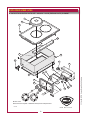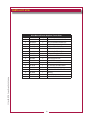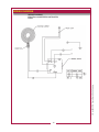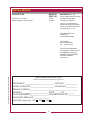
1
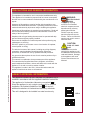
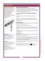
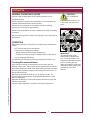
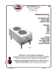
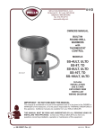
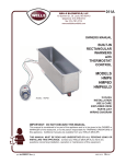
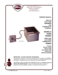
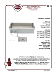
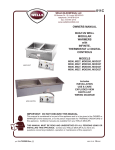
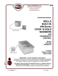
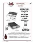
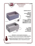
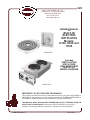
222
WELLS BLOOMFIELD, LLC
10 Sunnen Dr., St. Louis, MO 63143
telephone: 888-356-5362
fax: 314-781-2714
www.wells-mfg.com
OWNERS MANUAL
for
BUILT-IN
ELECTRIC
HOTPLATES
Models:
H336, H636 and
H706
Model H336
Includes
INSTALLATION
USE & CARE
EXPLODED VIEW
PARTS LIST
WIRING DIAGRAM
Model H706
IMPORTANT: DO NOT DISCARD THIS MANUAL
This manual is considered to be part of the appliance and is to be given to the OWNER or
MANAGER of the restaurant, or to the person responsible for TRAINING OPERATORS of
this appliance. Additional manuals are available from your WELLS DEALER.
THIS MANUAL MUST BE READ AND UNDERSTOOD BY ALL PERSONS USING OR
INSTALLING THIS APPLIANCE. Contact your WELLS DEALER if you have any
questions concerning installation, operation or maintenance of this equipment.
p/n 2M-303734 Rev. D
M222
110121
LIMITED WARRANTY STATEMENT
Unless otherwise specified, all commercial cooking
equipment manufactured by WELLS BLOOMFIELD, LLC is
warranted against defects in materials and workmanship
for a period of one year from the date of original installation
or 18 months from the date of shipment from our factory,
whichever comes first, and is for the benefit of the original
purchaser only.
personnel. The prices charged by Wells Bloomfield for its
products are based upon the limitations in this warranty.
Seller’s obligation under this warranty is limited to the
repair of defects without charge by a Wells Bloomfield
factory authorized service agency or one of its sub-service
agencies. This service will be provided on customer’s
premises for non-portable models. Portable models (a
device with a cord and plug) must be taken or shipped
to the closest authorized service agency, transportation
charges prepaid, for service. In addition to restrictions
contained in this warranty, specific limitations are shown in
the Service Policy and Procedure Guide. Wells Bloomfield
authorized service agencies are located in principal cities.
This warranty is valid in the United States and Canada and
void elsewhere. Please consult your classified telephone
directory, your foodservice equipment dealer or contact:
Wells Bloomfield, LLC
10 Sunnen Dr., St. Louis MO 63143 USA
phone (888) 356-5362 or fax (314) 781-2714
THIS WARRANTY IS THE COMPLETE AND ONLY
WARRANTY, EXPRESSED OR IMPLIED IN LAW
OR IN FACT, INCLUDING BUT NOT LIMITED TO,
WARRANTIES OF MERCHANTABILITY OR FITNESS
FOR ANY PARTICULAR PURPOSE, AND/OR FOR
DIRECT, INDIRECT OR CONSEQUENTIAL DAMAGES IN
CONNECTION WITH WELLS BLOOMFIELD PRODUCTS.
This warranty is void if it is determined that, upon inspection
by an authorized service agency, the equipment has
been modified, misused, misapplied, improperly installed,
or damaged in transit or by fire, flood or act of God. It
also does not apply if the serial nameplate has been
removed, or if service is performed by unauthorized
for information and other details concerning warranty.
SERVICE POLICY AND PROCEDURE GUIDE and ADDITIONAL WARRANTY EXCLUSIONS
2.
3.
4.
5.
6.
Resetting of safety thermostats, circuit breakers, over
load protectors, and/or fuse replacements are not
covered by this warranty unless warranted conditions are the cause.
All problems due to operation at voltages or phase other than specified on equipment nameplates are not covered by this warranty.
Conversion to correct voltage and/or phase must be the customer’s responsibility.
All problems due to electrical connections not made in accordance with electrical code requirements and wiring diagrams supplied with the equipment are not covered by this warranty.
Replacement of items subject to normal wear, to
include such items as knobs, light bulbs; and, normal maintenance functions including adjustments of
thermostats, adjustment of micro switches and
replacement of fuses and indicating lights are not
covered by warranty.
Damage to electrical cords and/or plug due to exposure
to excessive heat are not covered by this warranty.
Full use, care, and maintenance instructions supplied
with each machine. Noted maintenance and
preventative maintenance items, such as servicing and cleaning schedules, are customer responsibility. Those
miscellaneous adjustments noted are customer
responsibility. Proper attention to preventative
maintenance and scheduled maintenance procedures will prolong the life of the appliance.
7. Travel mileage is limited to sixty (60) miles from an Authorized Service Agency or one of its sub-service agencies.
8. All labor shall be performed during regular working
hours. Overtime premium will be charged to the buyer.
9. All genuine Wells replacement parts are warranted
for ninety (90) days from date of purchase on nonwarranty equipment. This parts warranty is limited only
to replacement of the defective part(s). Any use of
non-genuine Wells parts completely voids any
warranty.
10. Installation, labor, and job check-outs are not
considered warranty and are thus not covered by this warranty.
11. Charges incurred by delays, waiting time or operating restrictions that hinder the service technician’s ability to perform service are not covered by warranty. This includes institutional and correctional facilities.
SHIPPING DAMAGE CLAIM PROCEDURE
3.
NOTE: For your protection, please note that equipment
in this shipment was carefully inspected and packaged
by skilled personnel before leaving the factory. Upon
acceptance of this shipment, the transportation company
assumes full responsibility for its safe delivery.
IF SHIPMENT ARRIVES DAMAGED:
1. VISIBLE LOSS OR DAMAGE: Be certain that any
visible loss or damage is noted on the freight bill or
express receipt, and that the note of loss or damage is
signed by the delivery person.
2. FILE CLAIM FOR DAMAGE IMMEDIATELY:
Regardless of the extent of the damage.
CONCEALED LOSS OR DAMAGE: if damage is
unnoticed until the merchandise is unpacked, notify the transportation company or carrier immediately, and file “CONCEALED DAMAGE” claim with them. This should be done within fifteen (15) days from the date the delivery was made to you. Be sure to retain the container for inspection.
Wells Bloomfield cannot assume liability for damage or loss
incurred in transit. We will, however, at your request, supply
you with the necessary documents to support your claim.
xi
222 p/n 2M-303734 Owners Manual Built-In Hotplates
1.
TABLE OF CONTENTS
WARRANTY
SPECIFICATIONS
FEATURES & OPERATING CONTROLS
PRECAUTIONS & GENERAL INFORMATION
AGENCY APPROVAL INFORMATION
INSTALLATION
OPERATION
CLEANING INSTRUCTIONS
TROUBLESHOOTING
EXPLODED VIEW & PARTS LIST
PARTS & SERVICE
WIRING DIAGRAM
CUSTOMER SERVICE DATA
xi
1
2
3
3
4
5
6
7
8
12 - 17
18 - 19
19
INTRODUCTION
Thank You for purchasing this Wells Bloomfield appliance.
Proper installation, professional operation and consistent maintenance of this equipment will ensure that it
gives you the very best performance and a long, economical service life.
222 p/n 2M-303734 Owners Manual Built-In Hotplates
This manual contains the information needed to properly install this equipment, and to use and care for
the equipment in a manner which will ensure its optimum performance.
SPECIFICATIONS
MODEL
ELEMENT
H336
Single 8” Coil
H636
Dual 8” Coils
H706
Dual 9” french plates
VOLTS
AMPS
kW
208 V 1ø
9.4 A
2.0 kW
240 V 1ø
10.8A
2.6 kW
208 V 1ø
18.8 A
3.9 kW
240 V 1ø
21.7 A
5.2 kW
208 V 1ø
14.4 A
3.0 kW
240 V 1ø
16.7 A
4.0 kW
Refer to Installation Instructions for cutout dimensions.
1
*DIMENSIONS
10” outside diameter
14-3/4” W x 23-1/2” D
14-3/4” W x 23-1/2” D
FEATURES & OPERATING CONTROLS
Element Support
Heating
Element
Drip Pan
Heating Element
(Lifted)
Name Plate
Wellslok
Indicator
Light
Hotplate Unit
Temperature
Control IL2187
Control Unit
WELLSLOKS
Heating Element
HOTPLATE UNIT:
Provides heat for food preparation
Coil-type elements rotate for access to drip pan
Note: Solid (french plate) elements on model H-706 do not lift
Element Support*
Drip Pan*
Wellslok
Holds coil-type element in proper position
Collects drippings and holds element support.
Also deflects heat from element for more efficient cooking
Mounts hotplate unit to counter
CONTROL UNIT:
Infinite switch to control temperature of heating element
Temperature Control
Indicator Light
Clows any time temperature control is on
Name Plate
List manufacturer, model number and serial number, also lists voltage and wattage rating.
* = not used on model H706
2
222 p/n 2M-303734 Owners Manual Built-In Hotplates
IL2188
PRECAUTIONS AND GENERAL INFORMATION
This appliance is intended for use in commercial establishments only.
This appliance is intended to prepare food for human consumption.
No other use is recommended or authorized by the manufacturer or its
agents.
Operators of this appliance must be familiar with the appliance use,
limitations and associated restrictions. Operating instructions must be
read and understood by all persons using or installing this appliance.
Cleanliness of this appliance is essential to good sanitation. Read and
follow all included cleaning instructions and schedules to ensure the
safety of the food product.
Hotplates with coil-type heating elements must be operated with drip
pan and element support properly installed.
Disconnect the hotplate from electrical power before performing any
maintenance or servicing.
DO NOT splash or pour water over or into interior of hotplate,
control panel or wiring.
The technical content of this manual, including any wiring diagrams,
schematics, parts breakdown illustrations and/or adjustment
procedures, is intended for use by qualified technical personnel.
Any procedure that requires the use of tools must be performed by a
qualified technician.
This manual is considered to be a permanent part of the appliance.
This manual and all supplied instructions, diagrams, schematics,
parts breakdown illustrations, notices and labels must remain with the
appliance if it is sold or moved to another location.
WARNING:
ELECTRIC SHOCK
HAZARD
All servicing requiring
access to non-insulated
electrical components must
beperformed by a factory
authorized technician.
DO NOT open any access
panel that requires the use
of tools. Failure to follow this
warning can result in severe
electrical shock.
CAUTION:
RISK OF DAMAGE
DO NOT connect and/or
energize this appliance until
all installation instructions are
read and followed. Damage
to the appliance will result
if these instructions are not
followed.
222 p/n 2M-303734 Owners Manual Built-In Hotplates
This appliance is made in the USA. Unless otherwise noted, this
appliance has American sizes on all hardware.
AGENCY APPROVAL INFORMATION
This appliance conforms to NSF Standard 4 for sanitation only if
installed in accordance with the supplied Installation Instructions.
This appliance is Underwriters Laboratory recognized (
).
Since this appliance is only a single component of a complete
installation, the finished installation of this
unit requires
additional evaluations to Underwriters Laboratory standards.
This unit is designed to be installed in a metal counter only.
STD 4
3
INSTALLATION
UNPACKING & INSPECTION
Carefully remove the hotplate from the carton. Remove all
protective plastic film, packing materials and accessories from the
hotplate before connecting the hotplate to electrical power or otherwise performing any installation procedure.
Carefully read all instructions in this manual and the Installation
Instruction Sheet packed with the hotplate before starting any
installation.
Read and understand all labels and diagrams attached to the
hotplate.
Carefully account for all components and accessories before
discarding packing materials. Store all accessories in a convenient
place for later use.
BO
TT
OM
OF
CO
UN
TE
R
NOTE: DO NOT discard
the carton or other packing
materials until you have
inspected the appliance for
hidden damage and tested it
for proper operation.
Refer to SHIPPING
DAMAGE CLAIM
PROCEDURE on the inside
front cover of this
manual.
PREPARATION
Carefully the Installation Instruction Sheet packed with the hotplate for
cutout dimensions and restrictions.
Hotplate must be installed in a metal counter only.
IL2189
Supplied gasket must be installed under the mounting flange, and
the Wellsloks turned out to seal the hotplate and control unit to the
counter.
Apply a thin bead of food-grade silicone sealant where the flange
meets the counter.
IMPORTANT:
Contact a licensed electrician
to install and connect electrical
power to the hotplate.
ELECTRICAL
Hotplate must be installed by a licensed electrician in accordance with
all applicable codes and ordinances.
Refer to the nameplate. Verify the electrical service power. Voltage
and phase must match the nameplate specifications. Connecting the
hotplate to the wrong voltage can severely damage the equipment or
cause noticeably decreased performance.
The ground lug of the hotplate and control unit must be connected to
a suitable building ground.
INSTALLATION NOTE: The installation of
units requires
additional evaluations to Underwriters Laboratory standards.
IMPORTANT:
Damage due to being
connected to the wrong voltage
or phase is NOT covered by
Warranty.
4
222 p/n 2M-303734 Owners Manual Built-In Hotplates
IMPORTANT:
Water damage caused by
failure to seat Wellsloks or
failure to install gasket or to
seal flange to counter is NOT
covered by warranty
OPERATION
GENERAL OPERATIONAL NOTES
CAUTION:
Carefully read the description of the hotplate operation on the
HOT SURFACES
specification sheet.
DO NOT attempt to perform any maintenance or service unless the
hotplate is disconnected from electrical power.
DO turn the circuit breaker for the hotplate off before cleaning,
Exposed surfaces can be hot
to the touch and may cause
burns.
servicing or performing any maintenance.
DO NOT use sharp objects or metal implements to clean the heating
element(s).
DO use a plastic spatula or plastic scouring pad to remove burned-on
food product.
OPERATION
Each heating element is controlled by an infinite switch temperature
control:
OFF removes power from the element
LOW thru 8 are temperature settings
Higher numbers indicate higher temperatures
There is a continuous range of settings between LOW and HI
HI is a continuous ON setting
The indicator light will glow any time the temperature control is on.
222 p/n 2M-303734 Owners Manual Built-In Hotplates
Cooking Recommendations:
Save energy by turning the temperature control off any time the
hotplate is not in use. The coil-type heating elements will provide full
heat within 30 seconds, while french plate heating elements will reach
full heat within 2 minutes, making it unnecessary to leave the unit on
during intermittent use.
Each heating element can hold up to a 16 quart pot or pan. For
efficient heating of food product, pots and pans should be no more
than 10” in diameter.
Maximize the efficiency of solid (french plate) elements by using flatbottom pots and pans.
Stir thick liquids frequently to maintain a consistent temperature.
5
IMPORTANT:
The dial markings are an
INDICATION of temperature
only. The temperature of the
food product depends on many
factors, including the size,
shape and material of the food
container, and the quantity and
consistency of the food
product.
CLEANING INSTRUCTIONS
ELECTRIC SHOCK
HAZARD
Disconnect hotplate from
electric power before
cleaning.
PREPARATION
Unplug or disconnect hotplate from electrical power before cleaning.
Allow hotplate to cool completely before cleaning.
FREQUENCY
Daily
CAUTION:
TOOLS
BURN HAZARD
Plastic Spatula and Plastic Scouring Pad
Clean Cloth or Sponge
Mild Detergent or Cleaner Formulated for Stainless Steel
Warm Water
Allow hotplate element and
cabinet to cool completely
before cleaning.
CAUTION:
ELECTRIC SHOCK
HAZARD
Do not submerge hotplate in
water.
CLEANING
Disconnect hotplate from electrical power and allow heating elements
to cool completely before cleaning.
COILED HEATING ELEMENTS:
IMPORTANT: DO NOT spill
or pour water into interior of
hotplate.
Lift coiled heating elements and remove drip pans. Clean drip pans
with a plastic spatula or plastic scouring pad, mild detergent and warm
water. DO NOT use metal implements, steel wool or metal scouring
pads to clean drip pans. Rinse drip pans by wiping with a clean cloth
or sponge dampened with clean water.
IMPORTANT: DO NOT spill
or pour water into controls,
control panel or wiring.
Clean heating elements with a plastic spatula or plastic scouring pad,
mild detergent and warm water. DO NOT use metal implements, steel
wool or metal scouring pads to clean elements. Rinse by wiping with a
clean cloth or sponge dampened with clean water.
DO NOT submerge
hotplate in water. Damage
to internal components will
occur. Damage to internal
components from water
damage is NOT covered by
warranty.
Reinstall drip pans and gently lower heating element.
DO NOT use metal
implements, steel wool or
metal scouring pads to clean
heating elements.
FRENCH PLATE HEATING ELEMENTS:
French plate elements do not lift. Clean heating elements with a
plastic spatula or plastic scouring pad, mild detergent and warm water.
DO NOT use metal implements, steel wool or metal scouring pads to
clean elements. Rinse by wiping with a clean cloth or sponge
dampened with clean water.
Dry exposed portions of hotplate unit and control unit by wiping with a
clean soft dry cloth.
6
222 p/n 2M-303734 Owners Manual Built-In Hotplates
CAUTION:
TROUBLESHOOTING
SYMPTOM
Hotplate won’t heat
One or more sections
won’t heat
Hotplate not hot
enough
POSSIBLE CAUSE
SUGGESTED REMEDY
Disconnect OFF or circuit breaker tripped
Turn disconnect ON Check / reset
circuit breaker
Temperature control not on
Turn temperature control to desired
setting
Damaged temperature control, element or
other internal component
Contact Authorized Wells Service
Agency for repairs
Temperature control not set
Adjust for desired temperature
Operating 208/240V unit at 120V
Be sure supply voltage matches
nameplate voltage
Damaged temperature control, element or
other internal component
Contact Authorized Wells Service
Agency for repairs
222 p/n 2M-303734 Owners Manual Built-In Hotplates
NOTE: There are no user serviceable components in this
appliance. In all cases of damage or component malfunction,
contact your Authorized Wells Service Agency for repairs.
7
EXPLODED VIEW: H336
H336 BUILT-IN ELECTRIC HOTPLATE - 208/240V - SPIRAL ELEMENT
2.1
2.2
2
1
2.3
3
6
7
8
10
5
11
Model: H336
Built-In Electric Hotplate - 208/240V Spiral Element
PL222
IL1799 Rev. A 6/24/09
8
222 p/n 2M-303734 Owners Manual Built-In Hotplates
4
9
PARTS LIST: H336
H336 Built-n Electric Hotplate, Spiral Element
Fig No
Part No
Qty
Description
2C-33977
2
SCREW, 8-32X3/8-PHBNDHD
2
WS-50293
1
ELEMENT ASSY KIT, 240V @ 2600W
2.1
2N-30293ELUL
1
ELEMENT 240V 2600W
2.2
2P-6468
1
RING-ELEMENT ADAPTOR
2.3
2D-30293DT
1
DRIP TRAY
3
P2-31033
1
BOX CONTROL
4
2K-31040
1
BUSHING HEYCO 7/8” OD
5
2E-30562
1
SWITCH INFINITE 240V
6
P2-40843
1
BRKT MTG THERMO/INFINITE
7
2C-33935
1
SCREW 6ABX5/16 PH PAN SMS
8
WS-50385
1
LIGHT SIGNAL RED PUSH ON TERM
9
2C-31697
2
SCREW 8-32 X 3/16 PH RD HD
10
I7-Z12221
1
PANEL, FRONT/CONTROL
11
2R-30371
1
KNOB ASSY WARMERS
222 p/n 2M-303734 Owners Manual Built-In Hotplates
1
9
EXPLODED VIEW: H636
H-636 BUILT-IN ELECTRIC HOTPLATE - 208/240V - SPIRAL ELEMENT
3
4
2
5
1
6
7
8
13
7
14
15
16
9
10
11
17
6
18
Nameplate
Model: H636
Built-In Electric Hotplate - 208/240V Spiral Element
PL222
IL1800 Rev. B 1/21/11
10
222 p/n 2M-303734 Owners Manual Built-In Hotplates
12
PARTS LIST: H636
H636 Built-n Electric Hotplate, Spiral Element
Fig No
Part No
Qty
Description
2C-33977
4
SCREW, 8-32X3/8-PHBNDHD
2
WS-50293
2
ELEMENT ASSY KIT, 240V @ 2600W
3
2N-30293ELUL
2
ELEMENT 240V 2600W
4
2P-6468
2
RING-ELEMENT ADAPTOR
5
2D-30293DT
2
DRIP TRAY
6
2C-31697
4
SCREW, 8-32X3/16 PH RD HD
7
2K-37748X
2
FTG CONDUIT STRAIGHT 3/8
8
E7-49046
1
BOX OUTLET
9
WS-50131
1
TERM BLK KIT-3 POLE, 85AMP
10
2C-35736
2
NUT 8-32 HEX
11
2C-41974
2
NUT 8-32 HEX 7/8 LONG ALU
12
2E-30562
2
SWITCH INFINITE 240V
13
2C-33935
4
SCREW 6ABX1/16 PH PAN
14
WS-50385
2
LIGHT SIGNAL RED PUSH ON
15
2C-31053
8
NUT 8-32 KEPS MS NICKEL
16
P2-Z12288
1
PNL,CNTRL
17
2R-30584
1
KNOB RR
18
2R-30583
1
KNOB FR
222 p/n 2M-303734 Owners Manual Built-In Hotplates
1
11
EXPLODED VIEW: H706
H-706 BUILT-IN ELECTRIC HOTPLATE - 208/240V - SOLID (FRENCH PLATE) ELEMENT
1
2
3
17
4
5
6
6
10
9
8
3
16
5
11
5
15
13
12
14
Model: H706
Built-In Electric Hotplate - 208/240V Solid (French Plate) Element
PL222
IL1801 Rev. B 1/21/11
12
222 p/n 2M-303734 Owners Manual Built-In Hotplates
7
PARTS LIST: H706
H706 Built-In Electric Hotplate, French Plate
222 p/n 2M-303734 Owners Manual Built-In Hotplates
Fig No
Part No
Qty
Description
1
WS-503973
2
ELEM HPLATE UPGRADE FUSED
2
WS-503972
2
HPLATE UPGRADE CRACKED CE
3
2C-33935
8
SCREW 6AB X 5/16 PH PAN SMS
4
2C-31053
2
NUT 8-32 KEPS MS NICKEL
5
2C-31697
4
SCREW 8-32X3/16 PH RD HD
6
2K-37748X
2
FTG CONDUIT STRAIGHT 3/8
7
2C-31053
6
NUT 8-32 KEPS MS NICKEL
8
WS-50385
2
LIGHT SIGNAL RED PUSH ON
9
2E-30562
2
SWITCH INFINITE 240V
10
E7-49046
1
BOX OUTLET
11
WS-50131
1
TERM BLOCK KIT RETRO
12
2C-35736
1
NUT 8-32 HEX KEPS MS GREEN
13
2C-41974
2
NUT 8-32 HEX 7/8 LONG ALU
14
2R-30583
1
KNOB ASSY FRONT HOTPLATE
15
2R-30584
1
KNOB RR
16
P2-Z12288
1
PNL, CNTRL
17
I7-37930
1
CHANNEL ELEM MOUNT H706
13
WIRING DIAGRAM
222 p/n 2M-303734 Owners Manual Built-In Hotplates
WIRING DIAGRAM
ELECTRIC COUNTERTOP HOTPLATES
H-336
14
WIRING DIAGRAM
222 p/n 2M-303734 Owners Manual Built-In Hotplates
WIRING DIAGRAM
ELECTRIC COUNTERTOP HOTPLATES
H-636, H-656 and H-706
15
222 p/n 2M-303734 Owners Manual Built-In Hotplates
NOTES
16
PARTS & SERVICE
DESCRIPTION
SERVICE
PART NO.
Drip Tray, 8” for H-636
Element Support, H-636, H-656
21705
500039
IMPORTANT: Use only
factory authorized service parts
and replacement filters.
For factory authorized
service, or to order factory
authorized replacement parts,
contact your Wells authorized
service agency, or call:
Wells Bloomfield, LLC
10 Sunnen Dr.,
St. Louis MO 63143 USA
Service Dept.
phone: (888) 356-5362
fax:
(314) 781-2714
222 p/n 2M-303734 Owners Manual Built-In Hotplates
Service Parts Department
can supply you with the name
and telephone number of
the WELLS authorized
service agency
nearest you.
CUSTOMER SERVICE DATA
please have this information available if calling for service
RESTAURANT _____________________________ LOCATION _____________
INSTALLATION DATE ________________________ TECHNICIAN ___________
SERVICE COMPANY ________________________________________________
ADDRESS ___________________________ STATE ______ ZIP__________
TELEPHONE NUMBER (_____)_____-_________ EQUIPMENT MODEL NO. _______________
EQUIPMENT SERIAL NO. _______________
VOLTAGE: (check one) 120
208
240
17
WELLS BLOOMFIELD, LLC
10 Sunnen Dr., St. Louis, MO 63143
telephone: 888-356-5362
fax: 314-781-2714
www.wells-mfg.com