1
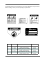
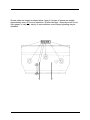
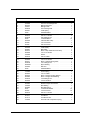
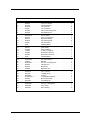
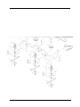
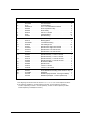
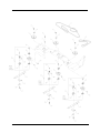
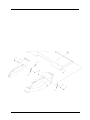
OWNER/OPERATOR S
MANUAL & PARTS
LIST
Tough-Cut Mower
Model HQ680
Revised 08-10-05
09.10014
Orrville, OH
www.ventrac.com
TO THE OWNER
Congratulations on the purchase of a new VENTRAC HQ680 Tough Cut Mower! The
purpose of this manual is to assist you in its safe and effective operation and
maintenance.
With proper usage and care, the Tough Cut Mower will provide many years of service.
Please read and understand this manual entirely before using the Tough Cut Mower.
Keep this manual on file for future reference.
Always give Model and Serial # when ordering service parts.
Please fill in the following information for future reference:
Date of Purchase: Month _________________ Day __________ Year ____________
Model Number: _______________________________________________________
Serial Number: ________________________________________________________
Dealer: ______________________________________________________________
Dealer Address: _______________________________________________________
_______________________________________________________
Dealer Phone Number: _________________________________________________
Dealer FAX Number: ___________________________________________________
Venture Products Inc. reserves the right to make changes in design or
specifications without incurring obligation to make like changes on
previously manufactured products.
ii
TABLE OF CONTENTS
INTRODUCTION
Section A
Description . . . . . . . . . . . . . . . . . . . . . . . . . . . . . . . . . . . . A-1
Specifications . . . . . . . . . . . . . . . . . . . . . . . . . . . . . . . . . . . A-2
SAFETY
Safety Symbols . . . . . . . .
Decals . . . . . . . . . . . . .
General Safety Procedures . .
Safety Operation & Techniques
Section B
.
.
.
.
.
.
.
.
.
.
.
.
.
.
.
.
.
.
.
.
.
.
.
.
.
.
.
.
.
.
.
.
.
.
.
.
.
.
.
.
.
.
.
.
.
.
.
.
.
.
.
.
.
.
.
.
.
.
.
.
.
.
.
.
.
.
.
.
.
.
.
.
.
.
.
.
.
.
.
.
.
.
.
.
.
.
.
.
.
.
.
.
OPERATION
.
.
.
.
.
.
.
.
B-1
B-2
B-3
B-4
Section C
Initial Jack Stand Installation . . . . .
Attaching . . . . . . . . . . . . . . .
Detaching . . . . . . . . . . . . . . .
Initial Setting of Hitch Pins . . . . . .
General Operating Techniques & Tips
Duals . . . . . . . . . . . . . . . . .
.
.
.
.
.
.
.
.
.
.
.
.
.
.
.
.
.
.
.
.
.
.
.
.
.
.
.
.
.
.
.
.
.
.
.
.
.
.
.
.
.
.
.
.
.
.
.
.
.
.
.
.
.
.
.
.
.
.
.
.
.
.
.
.
.
.
.
.
.
.
.
.
.
.
.
.
.
.
.
.
.
.
.
.
.
.
.
.
.
.
.
.
.
.
.
.
.
.
.
.
.
.
.
.
.
.
.
.
.
.
.
.
.
.
MAINTENANCE
Lubrication . . . . . . . . . . . .
Removal & Reinstallation of Blades
Sharpening Blades . . . . . . . .
Storage . . . . . . . . . . . . . .
Belt Replacement . . . . . . . . .
Main Deck Belt Replacement . . .
Right Belt Replacement . . . . . .
Drive Belt Replacement . . . . . .
.
.
.
.
.
.
.
.
.
.
. . C-1
. . C-2
. . C-2
. . C-2
C-3 & 4
. . C-5
Section D
.
.
.
.
.
.
.
.
.
.
.
.
.
.
.
.
.
.
.
.
.
.
.
.
.
.
.
.
.
.
.
.
.
.
.
.
.
.
.
.
PARTS & ILLUSTRATED DRAWINGS
Figure 1 Main Deck . . . . . . . . . . . .
Figure 2 — Hitch Arms . . . . . . . . . . .
Figure 3 — Spindles (Serial # AA1007-AA1275) .
Figure 3b - Spindles (Serial # AB1276--) . . . . .
Figure 4 — Cover Shield . . . . . . . . . .
WARRANTY
iii
.
.
.
.
.
.
.
.
.
.
.
.
.
.
.
.
.
.
.
.
.
.
.
.
.
.
.
.
.
.
.
.
.
.
.
.
.
.
.
.
.
.
.
.
.
.
.
.
.
.
.
.
.
.
.
.
.
.
.
.
.
.
.
.
.
.
.
.
.
.
.
.
.
.
.
.
.
.
.
.
.
.
.
.
.
.
.
.
.
.
.
.
.
.
.
.
.
.
.
.
.
.
.
.
.
.
.
.
.
.
.
.
.
.
.
.
.
.
.
.
.
.
.
.
.
.
.
.
.
.
.
.
.
.
.
.
.
.
.
.
.
.
.
.
.
.
.
.
.
.
.
.
D-1
D-2
D-2
D-2
D-3
D-3
D-3
D-3
Section E
. . . . . . . . . . . . . . . . . E-1 & 2
. . . . . . . . . . . . . . . . . E-3 & 4
. . . . . . . . . . . . . . . . . E-5 & 6
. . . . . . . . . . . . . . . . . . . E-5b & 6b
. . . . . . . . . . . . . . . . . E-7 & 8
INTRODUCTION
Product Description
The new VENTRAC Model HQ680 “Tough-Cut” rotary mower features an enclosed
deck designed for field and brush mowing. The broad, belted, high intake front creates
an “attack” on tall grasses and brush before it is leveled. The straight front deck design
provides structural strength and a uniform performance in tall vegetation.
Two cast-iron gauge wheels with 5/8th inch rubber coating, roller bearings and grease
zerks help to gauge the mowing depth and reduce scalping. They can be adjusted to
three cut heights.
The VENTRAC “Quick Attach” makes the “Tough-Cut” a quick option among the
VENTRAC’s (4000 series) many attachments. Variables in tractor hitch heights can be
accommodated by properly positioning the hitch pins in the deck frame. Easy servicing
is provided by the hinged and removable cover and deck tilt to access the underside
and blades.
Power consumption is always relative to numerous factors but generally the
“Tough-Cut” operates easily and does not necessarily require full engine rpms.
Proper service, maintenance and safe operation of the HQ680 “Tough-Cut” will provide
great results for field and brush mowing.
A-1
INTRODUCTION
Ventrac HQ680 Specifications
Overall Width . . . . . . . . . . . . . . . . . . . . . . . . . . . 68 inches
Length . . . . . . . . . . . . . . . . . . . . . . . . . . . . . . . 46 inches
Height . . . . . . . . . . . . . . . . . . . . . . . . . . . . . . . 18 inches
Weight . . . . . . . . . . . . . . . . . . . . . . . . . . . . . . 325 pounds
Blades . . . . . . . . . . . . . . . . . . . . . . . . . . . . . . . . . . . . 3
6 gauge wheels . . . . . . . . . . . . . . . . . . . . . . . . . . . . . . 2
Cutting height adjustments . . . . . . . . . . . . . . . . 3 , 3-5/8 , 4-1/4
These specifications are subject to change without notice.
A-2
SAFETY
ATTENTION:
This symbol identifies potential health and
safety hazards. It marks safety
precautions. Your safety and the safety of
others is involved.
SIGNAL WORD DEFINITIONS
Indicates an imminently hazardous
situation which, if not avoided, will result in
death or serious injury. This signal word is
limited to the most extreme cases.
Indicates a potentially hazardous situation
which, if not avoided, could result in death
or serious injury.
Indicates a potentially hazardous situation
which, if not avoided, may result in minor
or moderate injury and/or property
damage. It may also be used to alert
against unsafe practices.
B-1
SAFETY
The following decals must be maintained on your Ventrac Attachment. If any decals are
faded or missing, contact your dealer promptly for replacements.
B
A
C
E
D
Decal
Page &
Location
Description
Part Number
A
E-1, #28
Danger Shield Missing
00.0062
B
E-1, #20
Warning Moving Part Hazard
00.0101
C
E-1, #27
Danger Pinching Hazard
00.0102
D
E-1, #15 (2)
Keep Hands and Feet Away
00.0123
Ventrac Serial No. Plate
00.0128
E
B-2
SAFETY
General Safety Procedures
for Ventrac Tractors, Attachments, & Accessories
Read and understand the operator’s manual before operating this equipment.
Observe and follow all safety decals.
DO NOT let children or any untrained person operate the tractor or attachment.
Make sure that all operators of this equipment are thoroughly trained in using it
safely.
Never allow additional riders on the tractor or attachments.
DO NOT operate tractor or attachments if you are under the influence of alcohol,
drugs, medication that may impair judgment or cause drowsiness, or if you are not
feeling well.
Operate all controls from the operators seat only.
Before operating equipment, make sure all shields are in place and fastened.
Ensure the attachment or accessory is locked or fastened securely to the tractor
(power unit) before operating. See tractor manual for locking procedure.
Ensure that all bystanders are clear of the tractor and attachment before operating.
Be especially careful and observant if other people are present. Never assume that
bystanders will remain where you last saw them.
Always look in the direction the tractor is moving.
Never direct the discharge of any attachment in the direction of people, animals,
buildings, vehicles, or objects of value.
Immediately stop at any sign of equipment failure and correct the problem before
continuing to operate. An unusual noise can be a warning of equipment failure.
Before adjusting, cleaning, lubricating, or changing parts on the tractor or attachment,
engage the parking brake, lower the attachment to the ground, stop the engine, and
remove the ignition key.
To prevent the risk of uncontrolled equipment movement on tractors equipped with 2
speed axles, always shift the transaxle range with the power unit stationary on level
ground and with the parking brake engaged.
If equipment is to be left unattended, engage the parking brake, lower the attachment
to the ground, stop the engine, and remove the ignition key.
B-3
SAFETY
HQ680 Safety Procedures
Before making any repairs or adjustments, lower
attachment to the ground, set parking brake, shut
the engine off, and remove the key.
Read and understand the operator’s manual before
operating this equipment.
• Do not mow in areas that contain stones, sticks or other foreign objects that may be
thrown from the mower.
• Rotating Blades Are Dangerous
• Stop the machine if a person enters the mowing area.
• Be alert at all times; drive carefully because people and especially CHILDREN can
move quickly into the mowing area.
• Shut off PTO when you are not mowing.
• Use extra care when you come to shrubs, trees, or objects that may block your vision.
• Never mow toward a person or object of value.
B-4
OPERATION
Setup Instructions for the HQ680 Tough Cut Mower
Jack Stand Installation:
To install the jack stand into the mounting tube as shown below, raise the back of the
mower far enough to insert the stand in the tube. This can be accomplished be setting
the mower crosswise on the crate or using a lifting device. Remember, whatever
method is used keep safety in mind and use common safety procedures such as using
stands, blocking, or a restraining device.
Remove the tyton tie which holds the latch handle to the mounting tube. Insert the jack
stand into the mounting tube as shown in fig.1. Ensure that the bolt hole in the top of
the jack stand faces to the right side of the deck. (Refer to the parts drawing on pg. E-1
for further reference). Remove the outer nut from the latch handle, insert the bolt
through the jack stand and replace the nut. Adjust spring tension as tight as possible,
while still allowing the jack stand latch to operate freely in and out of the notch when
raising or lowering the jack stand.
When mowing or transporting, the jack stand should always be in the very top setting.
(Refer to pg. C-2). For tilting the deck up, move the jack stand to the middle setting
(refer to pg. C-4). This will allow for ground clearance as well as to ensure the jack
stand does not hit the front of the tractor. To disconnect the deck from the tractor, lower
the stand to the lowest setting prior to removing the mower from the tractor. (Refer to
pg. C-2).
REF
PART #
DESCRIPTION
7
90.0612
3/8-16 X 1-1/2 BOLT
1
8
99.SF06
3/8-16 FLANGE NUT
2
38
62.1011
JACK STAND
1
39
64.1114
JACK STAND LATCH
1
40
41.0039
9/16 OD X 5/8 COMPRESSION SPRING
1
C-1
QTY
OPERATION
OPERATING INSTRUCTIONS
Attaching:
1. Drive the tractor slowly forward into the mating arms on the mower. Align the hitch
arms to complete the engagement.
2. Once completely engaged, close the front hitch latch.
3. Stop the tractor engine.
4. Place attachment belt over the outside groove of the PTO drive pulley on the tractor.
5. Engage the PTO spring tension lever.
6. Lift up jack stand.
7. If your VENTRAC 4000 series has a traction transfer system, engage according to
instructions in tractor owner’s manual.
8. Make sure the tractor has enough counterweight installed to keep the rear tires on
the ground at all times. The amount of counterweight needed will depend on the
terrain, slopes, and the manner in which the tractor is operated.
Detaching:
Park the tractor on a level surface and set the parking brake.
1. Raise the deck all the way up.
2. Stop the tractor engine.
3. Release the PTO lever slowly.
4. Dismount and remove the PTO belt from the tractor drive pulley.
5. Lower jack stand.
6. Disengage the hitch latch.
7. Slowly back tractor away from the mower or carefully pull the mower from the tractor
by hand. NOTE: If traction transfer system is engaged, lower the hitch enough to
relieve the lift pressure on the attachment.
Initial Setting of Hitch Pins:
Four Hitch pins control the fore-to-aft level of the deck. On a hard surface, the deck
should be level or slightly higher (1/4”) at the back.
Position the pins in the hitch area so that the deck retains this position at all times. If the
cut height is changed, the pin locations may need to be altered.
C-2
OPERATION
Operating Techniques and Tips:
With a little practice, operation of the mower will become very easy and simple. Always
keep SAFETY as the First Priority. Remember to keep the size of the task appropriate
to the size of the equipment.
Always shut off engine and remove key to clean or make adjustments on the mower.
Travel to and from the area to be mowed should be done with the mower raised in
transport position by the tractor hydraulics. This saves the wear-and-tear on the mower
and needless scuffing and rolling over the various surfaces between mowing jobs.
Moderate speed should be used in transport in order to maintain control and reduce the
shock load from uneven terrain. Disengage the PTO to prevent air turbulence over
dusty surfaces and/or when traveling over rough terrain.
Operator must be sitting on the tractor seat and seat belt fastened before the PTO can
be engaged. Have the engine rpms between 2,000 and 3,000 before engaging the PTO
switch. Near full engine rpms (3,600) is recommended for most mowing. If a good cut
can be maintained and there is sufficient power, reducing the rpms by 200 or 300 will
result in a little better fuel economy and reduction in the wear-and-tear on the
equipment.
When mowing, place the front hitch hydraulic control lever in the FLOAT position by
moving it outward until the detent engages. The lever will stay in this position after
engagement.
Be very cautious when mowing slopes. It is recommended that both traction transfer
springs be engaged. See C-5 for Dual Wheel option.
C-3
OPERATION
Operating Techniques and Tips (cont.)
Wet or lush grass has some tendency to build up under the deck. Clean deck
periodically and particularly if and when mowing performance seems to be
reduced.
Cleaning Procedure
1. Raise the deck all the way up.
2. Turn the tractor off.
3. Remove the 2 ball pins from on top of the Hitch Arms.
4. Move the jack stand to the middle notch.
5. Lift the front of the deck up, placing the ball pins in the front locking holes.
Blades should be kept in good condition. Sharp blades will increase efficiency
and improve the quality of cut.
When mowing grass on level to gently rolling terrain, the tractor can be
operated in HIGH range in most conditions. If the grass is tall or mowing
conditions are difficult, use LOW range. When mowing slopes, always use
LOW range with the engine at full throttle.
CAUTION: Always shift transaxle range with the tractor parked on LEVEL
ground. Never shift on a slope since all hydraulic braking capacity will
be lost during the shifting process.
Many different circumstances and situations can occur for which the operator
must determine a safe way to operate the tractor and mower. Always follow
safety procedures and always use common sense.
Approach every task with an underlying consideration for your safety as
well as for the safety of anyone who happens to be near your work area.
Make sure that all operators of this equipment are thoroughly trained in
using it safely.
Never mow with the front of the mower directed toward people or
anything that could be damaged by a thrown object!
C-4
OPERATION
Use of Duals for Mowing
On level to modest inclines, single tires will suffice. Single tires should be inflated to 7
psi and outside dual tires to 3-4 psi. Lower inflation pressure reduces grass and soil
compaction.
On significant inclines, even if only a small portion of the total mowing to be done, the
tractor should be equipped with dual tires for increased stability. If you are uncertain
about the need for duals, you should favor using them for your own SAFETY.
When using the mower deck, both traction boosters should be engaged to increase
stability and provide safer operation.
Note: Factory recommends heavy axle kit to be used with all dual installations.
C-5
MAINTENANCE
Lubrication
Grease zerks are located as shown below. Apply 2-3 pumps of grease per spindle
approximately every 50 hours of operation. All other bearings—one pump max! Do not
over grease. In very dirty, sandy, or wet conditions, more frequent greasing may be
advisable.
D-1
MAINTENANCE
Belt Replacement:
If belts become excessively worn or cracked, install a new belt. This is done most
easily with the deck removed from the tractor.
Main Deck Belt Replacement:
1. Remove old belt. Note that one belt loop must surround the left hitch arm.
Remove left hitch arm for access.
2. Install the replacement belt as shown in the diagram below. Begin by placing one
belt loop around the left hitch arm. Place belt into the idler pulley and then the drive
pulley. Take the belt to the right double groove pulley rotating the belt 1/4 turn into
the pulley groove.
3. Once around the pulley, follow the diagram to the other pulleys. Note: The
“V” shape of the belt should fit nicely into each pulley groove. Belt twist
should never exceed 1/4 turn.
4. Tension the belt by tightening the idler adjustment rod. The spring loops should
have approximately .05 inches between them.
Note: a rule of thumb is to slip a paper clip between them.
Right Belt Replacement:
Remove main deck belt. Install replacement belt as shown. Reinstall the main deck
belt.
Drive Belt Replacement:
Remove mower from tractor. Remove pulley cover, replace belt over pulley and left
hitch arm. Reinstall cover.
D-3
PARTS & DRAWINGS
FIGURE 1
ILLUSTRATED DRAWING
MAIN DECK
E-1
PARTS & DRAWINGS
FIGURE 1
MAIN DECK
REF.
1
2
3
4
5
6
PART NO.
DESCRIPTION
QTY.
.
.
.
.
.
.
.
.
.
.
.
.
.
.
.
.
.
.
.
.
.
.
.
.
.
.
.
.
.
.
.
.
.
.
.
.
97.0506.
60.0793.
44.0191.
99.SF05
83.0031.
94.06 . .
.
.
.
.
.
.
.
.
.
.
.
.
.
.
.
.
.
.
.
.
.
.
.
.
.
.
.
.
.
.
.
.
.
.
.
.
.
.
.
.
.
.
.
.
.
.
.
.
.
.
.
.
.
.
5/16-18 x 3/4 Carriage Bolt
Belting Clamp Bar . . . . .
Belting Curtain . . . . . . .
5/16-18 Flange Nut . . . .
V-Idler pulley . . . . . . . .
3/8 USS Washer . . . . . .
.
.
.
.
.
.
.
.
.
.
.
.
7 .
8 .
9 .
10
11
12
.
.
.
.
.
.
.
.
.
.
.
.
.
.
.
.
.
.
.
.
.
.
.
.
.
.
.
.
.
.
90.0612.
99.SF06
95.08 . .
83.0039.
99.A08 .
99.A06 .
.
.
.
.
.
.
.
.
.
.
.
.
.
.
.
.
.
.
.
.
.
.
.
.
.
.
.
.
.
.
.
.
.
.
.
.
.
.
.
.
.
.
.
.
.
.
.
.
.
.
.
.
.
.
3/8-16 x 1-1/2 Bolt . . . . . . . . . . . . . . . . . 2
3/8-16 Flange Nut . . . . . . . . . . . . . . . . . 5
1/2 SAE Washer. . . . . . . . . . . . . . . . . . 10
2 Groove Idler Pulley. . . . . . . . . . . . . . . . 1
1/2-13 Lock Nut . . . . . . . . . . . . . . . . . . 3
3/8-16 Lock Nut . . . . . . . . . . . . . . . . . . 2
13
14
15
16
17
18
.
.
.
.
.
.
.
.
.
.
.
.
.
.
.
.
.
.
.
.
.
.
.
.
.
.
.
.
.
.
83.0038.
62.0897.
00.0123.
90.0828.
53.0098.
90.0616.
.
.
.
.
.
.
.
.
.
.
.
.
.
.
.
.
.
.
.
.
.
.
.
.
.
.
.
.
.
.
.
.
.
.
.
.
.
.
.
.
.
.
.
.
.
.
.
.
.
.
.
.
.
.
V-Idler Pulley . . . . . . . . . . . . .
Main Deck . . . . . . . . . . . . . .
Decal - Keep Hands and Feet Away .
1/2-13 x 3-1/2 Bolt . . . . . . . . . .
Wheel . . . . . . . . . . . . . . . .
3/8-16 x 2 Bolt . . . . . . . . . . . .
.
.
.
.
.
.
.
.
.
.
.
.
.
.
.
.
.
.
.
.
.
.
.
.
.
.
.
.
.
.
.
.
.
.
.
.
.
.
.
.
.
.
2
1
2
2
2
1
19
20
21
22
23
24
.
.
.
.
.
.
.
.
.
.
.
.
.
.
.
.
.
.
.
.
.
.
.
.
.
.
.
.
.
.
90.0826. .
00.0101. .
99.SF08 .
85.B0027 .
40.0292. .
95.06 . . .
.
.
.
.
.
.
.
.
.
.
.
.
.
.
.
.
.
.
.
.
.
.
.
.
.
.
.
.
.
.
.
.
.
.
.
.
.
.
.
.
.
.
.
.
.
.
.
.
1/2-13 x 3-1/4 Bolt . . . . . .
Decal - Hazard, Moving Parts
1/2-13 Flange Nut . . . . . .
Nylon Bushing . . . . . . . .
Idler Arm . . . . . . . . . . .
3/8 SAE Washer . . . . . . .
.
.
.
.
.
.
.
.
.
.
.
.
.
.
.
.
.
.
.
.
.
.
.
.
.
.
.
.
.
.
.
.
.
.
.
.
.
.
.
.
.
.
1
1
2
2
1
7
25
26
27
28
29
30
.
.
.
.
.
.
.
.
.
.
.
.
.
.
.
.
.
.
.
.
.
.
.
.
.
.
.
.
.
.
41.0066.
90.0832.
00.0102.
00.0062.
99.SF04
90.0406.
.
.
.
.
.
.
.
.
.
.
.
.
.
.
.
.
.
.
.
.
.
.
.
.
.
.
.
.
.
.
.
.
.
.
.
.
.
.
.
.
.
.
.
.
.
.
.
.
.
.
.
.
.
.
Torsion Spring . . . . . . . . . . . . . . . . . . . 1
1/2-13 x 4 Bolt . . . . . . . . . . . . . . . . . . . 1
Decal - Danger, Pinching Hazard . . . . . . . . . 1
Decal - Danger, Shield Missing . . . . . . . . . . 1
1/4-20 Flange Nut . . . . . . . . . . . . . . . . . 2
1/4-20 x 3/4 Bolt . . . . . . . . . . . . . . . . . . 12
31
32
33
34
35
36
.
.
.
.
.
.
.
.
.
.
.
.
.
.
.
.
.
.
.
.
.
.
.
.
.
.
.
.
.
.
05.0095.
44.0209.
60.0882.
95.04 . .
99.A04 .
90.0610.
.
.
.
.
.
.
.
.
.
.
.
.
.
.
.
.
.
.
.
.
.
.
.
.
.
.
.
.
.
.
.
.
.
.
.
.
.
.
.
.
.
.
.
.
.
.
.
.
.
.
.
.
.
.
Rubber Bumper with Washer . . . . . . . . . . . 2
Rear Belting . . . . . . . . . . . . . . . . . . . . 1
Rear Belt Clamp . . . . . . . . . . . . . . . . . . 1
1/4 SAE Flat Washer . . . . . . . . . . . . . . . 10
1/4-20 Lock Nut . . . . . . . . . . . . . . . . . . 10
3/8-16 x 1-1/4 Bolt . . . . . . . . . . . . . . . . . 1
.
.
.
.
.
.
.
.
.
.
.
.
.
.
.
.
.
.
.
.
.
.
.
.
.
.
.
.
.
.
.
.
.
.
.
.
.
.
.
.
.
.
.
.
.
.
.
.
.
.
.
.
.
.
.
.
.
.
.
.
.
.
.
.
.
.
.
.
.
.
.
.
.
.
.
.
.
.
.
.
.
.
.
.
7
1
1
7
1
5
37 . . . . . 62.1011 . . . . . . . . . . Jack Stand . . . . . . . . . . . . . . . . . . . . . 1
38 . . . . . 64.1114 . . . . . . . . . . Jack Stand Latch. . . . . . . . . . . . . . . . . . 1
39 . . . . . 41.0039. . . . . . . . . . 9/16 OD x 5/8 Compression Spring . . . . . . . . 1
E-2
PARTS & DRAWINGS
FIGURE 2
ILLUSTRATED DRAWING
HITCH ARMS
E-3
PARTS & DRAWINGS
FIGURE 2
HITCH ARMS
REF.
1
2
3
4
5
6
PART NO.
DESCRIPTION
QTY.
.
.
.
.
.
.
.
.
.
.
.
.
.
.
.
.
.
.
.
.
.
.
.
.
.
.
.
.
.
.
.
.
.
.
.
.
90.0812.
60.0792.
85.SC08
99.A08 .
97.0606.
99.SF06
.
.
.
.
.
.
.
.
.
.
.
.
.
.
.
.
.
.
.
.
.
.
.
.
.
.
.
.
.
.
.
.
.
.
.
.
.
.
.
.
.
.
.
.
.
.
.
.
.
.
.
.
.
.
1/2-13 x 1-1/2 Bolt . . . .
Left Deck Bracket . . . .
1/2” Set Collar . . . . . .
1/2-13 Lock Nut . . . . .
3/8-16 x 3/4 Carriage Bolt
3/8-16 Flange Nut . . . .
.
.
.
.
.
.
.
.
.
.
.
.
.
.
.
.
.
.
.
.
.
.
.
.
.
.
.
.
.
.
.
.
.
.
.
.
.
.
.
.
.
.
.
.
.
.
.
.
.
.
.
.
.
.
.
.
.
.
.
.
.
.
.
.
.
.
.
.
.
.
.
.
.
.
.
.
.
.
4
1
2
4
8
8
7 .
8 .
9 .
10
11
12
.
.
.
.
.
.
.
.
.
.
.
.
.
.
.
.
.
.
.
.
.
.
.
.
.
.
.
.
.
.
02.HP0416
03.0810. .
60.0791. .
99.SF05 .
99.A06 . .
95.06 . . .
.
.
.
.
.
.
.
.
.
.
.
.
.
.
.
.
.
.
.
.
.
.
.
.
.
.
.
.
.
.
.
.
.
.
.
.
.
.
.
.
.
.
.
.
.
.
.
.
1/8 x 2 Hairpin . . . .
1/2 x 1-1/4 Clevis Pin
Right Deck Bracket .
5/16-18 Flange Nut .
3/8-16 Lock Nut . . .
3/8 SAE Washer . . .
.
.
.
.
.
.
.
.
.
.
.
.
.
.
.
.
.
.
.
.
.
.
.
.
.
.
.
.
.
.
.
.
.
.
.
.
.
.
.
.
.
.
.
.
.
.
.
.
.
.
.
.
.
.
.
.
.
.
.
.
.
.
.
.
.
.
.
.
.
.
.
.
.
.
.
.
.
.
.
.
.
.
.
.
.
.
.
.
.
.
4
4
1
8
1
1
13
14
15
16
17
18
.
.
.
.
.
.
.
.
.
.
.
.
.
.
.
.
.
.
.
.
.
.
.
.
.
.
.
.
.
.
83.0031.
42.0385.
41.0048.
40.0293.
40.0291.
95.08 . .
.
.
.
.
.
.
.
.
.
.
.
.
.
.
.
.
.
.
.
.
.
.
.
.
.
.
.
.
.
.
.
.
.
.
.
.
.
.
.
.
.
.
.
.
.
.
.
.
.
.
.
.
.
.
V-Idler Pulley . . . . . .
Spring Tensioner . . . .
1” OD x 6-1/2 Spring . .
Hitch Mount Idler Arm .
Hitch Mount Idler Pivot .
1/2 SAE Washer . . . .
.
.
.
.
.
.
.
.
.
.
.
.
.
.
.
.
.
.
.
.
.
.
.
.
.
.
.
.
.
.
.
.
.
.
.
.
.
.
.
.
.
.
.
.
.
.
.
.
.
.
.
.
.
.
.
.
.
.
.
.
.
.
.
.
.
.
.
.
.
.
.
.
.
.
.
.
.
.
.
.
.
.
.
.
1
1
1
1
1
2
19
20
21
22
23
24
.
.
.
.
.
.
.
.
.
.
.
.
.
.
.
.
.
.
.
.
.
.
.
.
.
.
.
.
.
.
02.CP0406
81.B045 .
99.SF0506
62.0899. .
80.0312. .
62.0898. .
.
.
.
.
.
.
.
.
.
.
.
.
.
.
.
.
.
.
.
.
.
.
.
.
.
.
.
.
.
.
.
.
.
.
.
.
.
.
.
.
.
.
.
.
.
.
.
.
1/8 x 3/4 Cotter Pin . . .
B45 Belt . . . . . . . . .
5/16-18 x 3/4 Flange Bolt
Left Hitch Arm . . . . . .
Drive Shaft . . . . . . . .
Right Hitch Arm . . . . .
.
.
.
.
.
.
.
.
.
.
.
.
.
.
.
.
.
.
.
.
.
.
.
.
.
.
.
.
.
.
.
.
.
.
.
.
.
.
.
.
.
.
.
.
.
.
.
.
.
.
.
.
.
.
.
.
.
.
.
.
.
.
.
.
.
.
.
.
.
.
.
.
.
.
.
.
.
.
1
1
2
1
1
1
25
26
27
28
29
30
.
.
.
.
.
.
.
.
.
.
.
.
.
.
.
.
.
.
.
.
.
.
.
.
.
.
.
.
.
.
85.K0410 . . .
83.H16S . . .
83.BK50H . .
55.FB16016-1
60.0665. . . .
99.E0004 . . .
.
.
.
.
.
.
.
.
.
.
.
.
.
.
.
.
.
.
.
.
.
.
.
.
.
.
.
.
.
.
.
.
.
.
.
.
1/4 x 1-1/4 Key . . . . .
1” Split Bushing . . . .
5” Pulley . . . . . . . .
1” Flange Block Bearing
Drive Pulley Shield . . .
1/4-20 Wing Nut . . . .
.
.
.
.
.
.
.
.
.
.
.
.
.
.
.
.
.
.
.
.
.
.
.
.
.
.
.
.
.
.
.
.
.
.
.
.
.
.
.
.
.
.
.
.
.
.
.
.
.
.
.
.
.
.
.
.
.
.
.
.
.
.
.
.
.
.
.
.
.
.
.
.
.
.
.
.
.
.
2
2
1
2
1
1
.
.
.
.
.
.
31 . . . . . 99.SF0508 . . . . . . . . 5/16-18 x 1 Flange Bolt . . . . . . . . . . . . . . 4
32 . . . . . 83.BK55H . . . . . . . . 5-1/2” Pulley . . . . . . . . . . . . . . . . . . . . 1
33 . . . . . 85.B0027 . . . . . . . . . Nylon Bushing . . . . . . . . . . . . . . . . . . . 2
E-4
PARTS & DRAWINGS
FIGURE 3
ILLUSTRATED DRAWING
SPINDLES (Serial # AA1007-AA1275)
E-5
PARTS & DRAWINGS
FIGURE 3
SPINDLES (Serial # AA1007-AA1275)
REF.
PART NO.
DESCRIPTION
QTY.
1 .
2*.
. .
3*.
. .
4 .
5 .
6 .
.
.
.
.
.
.
.
.
.
.
.
.
.
.
.
.
.
.
.
.
.
.
.
.
.
.
.
.
.
.
.
.
.
.
.
.
.
.
.
.
99.A12NF .
95.12 . . . .
99.B0057-2 .
83.0036. . .
83.0048. . .
90.0610. . .
95.06 . . . .
55.0035. . .
.
.
.
.
.
.
.
.
.
.
.
.
.
.
.
.
.
.
.
.
.
.
.
.
.
.
.
.
.
.
.
.
.
.
.
.
.
.
.
.
.
.
.
.
.
.
.
.
.
.
.
.
.
.
.
.
3/4-16 Lock Nut . . . . . . . . . . . . . . . . . . 3
3/4 SAE Washer . . . . . . . . . . . . . . . . . . 3
3/4 x 1-1/4 10GA Machine Washer . . . . . . . . 3
D-Hex Top Mount Pulley . . . . . . . . . . . . . . 2
D-Hex Pulley . . . . . . . . . . . . . . . . . . . . 3
3/8-16 x 1-1/4 Bolt. . . . . . . . . . . . . . . . . 24
3/8 SAE Washer. . . . . . . . . . . . . . . . . . 24
Spindle Bearing . . . . . . . . . . . . . . . . . . 6
7 .
8 .
9 .
10
11*
. .
12*
. .
.
.
.
.
.
.
.
.
.
.
.
.
.
.
.
.
.
.
.
.
.
.
.
.
.
.
.
.
.
.
.
.
.
.
.
.
.
.
.
.
87.0178. .
87.0179. .
29.GF0001
99.SF06 .
87.0181. .
87.0206-1
87.0184-1
87.0205-1
.
.
.
.
.
.
.
.
.
.
.
.
.
.
.
.
.
.
.
.
.
.
.
.
.
.
.
.
.
.
.
.
.
.
.
.
.
.
.
.
.
.
.
.
.
.
.
.
.
.
.
.
.
.
.
.
.
.
.
.
.
.
.
.
Spindle Housing . . . . . . . . . . . . . . . . . . 3
Bearing Spacer. . . . . . . . . . . . . . . . . . . 3
1/4-28 Grease Fitting . . . . . . . . . . . . . . . 3
3/8-16 Flange Nut . . . . . . . . . . . . . . . . . 24
Spindle Shaft - Right Hand Thread . . . . . . . . 2
Spindle Shaft - Right Hand Thread . . . . . . . . 2
Spindle Shaft - Left Hand Thread . . . . . . . . . 1
Spindle Shaft - Left Hand Thread . . . . . . . . . 1
13*
. .
14*
. .
15
16
17
18
.
.
.
.
.
.
.
.
.
.
.
.
.
.
.
.
.
.
.
.
.
.
.
.
.
.
.
.
.
.
.
.
.
.
.
.
.
.
.
.
87.0184.
87.0205.
87.0176.
87.0206.
79.0048.
64.0688.
91.0810.
91.0810L
.
.
.
.
.
.
.
.
.
.
.
.
.
.
.
.
.
.
.
.
.
.
.
.
.
.
.
.
.
.
.
.
.
.
.
.
.
.
.
.
.
.
.
.
.
.
.
.
.
.
.
.
.
.
.
.
.
.
.
.
.
.
.
.
.
.
.
.
.
.
.
.
Spindle Assembly - 1/2-20 LH Thread .
Spindle Assembly - 1/2-20 LH Thread .
Spindle Assembly - 1/2-20 RH Thread.
Spindle Assembly - 1/2-20 RH Thread.
Bi-directional Blade . . . . . . . . . .
Spindle Guard . . . . . . . . . . . . .
1/2-20 x 1-1/4 Bolt . . . . . . . . . . .
1/2-20 x 1-1/4 LH Bolt . . . . . . . . .
.
.
.
.
.
.
.
.
1
1
2
1
3
3
2
1
19*
20
21
. .
.
.
.
.
.
.
.
.
.
.
.
.
.
.
.
.
.
.
.
.
83.0043. .
81.AA060 .
81.B158 .
81.B162 .
.
.
.
.
.
.
.
.
.
.
.
.
.
.
.
.
.
.
.
.
.
.
.
.
.
.
.
.
.
.
.
.
D-Hex Bottom Mount Pulley (same as item 3 now)
AA60 Belt . . . . . . . . . . . . . . . . . . . . .
B158 Belt (Dayco/Carlisle - No longer available) .
B162 Belt (Goodyear - Current replacement) . . .
0
1
1
1
.
.
.
.
.
.
.
.
.
.
.
.
.
.
.
.
.
.
.
.
.
.
.
.
.
.
.
.
.
.
.
.
.
.
.
.
.
.
.
.
* Note: Beginning with serial number AA1150, item 2, 3, 11, 12, 13, 14, & 19 were replaced as follows:
95.12 replaced by 99.B0057-2. 83.0036 replaced by 83.0048. 87.0181 replaced by 87.0206-1.
87.0184-1 replaced by 87.0205-1. 87.0184 replaced by 87.0205. 87.0176 replaced by 87.0206.
83.0043 replaced by 83.0048(same as item 3) .
E-6
PARTS & DRAWINGS
FIGURE 3b
ILLUSTRATED DRAWING
SPINDLES (Serial # AB1276--)
E-5b
PARTS & DRAWINGS
FIGURE 3b
SPINDLES (Serial # AB1276--)
REF.
1
2
3
4
5
6
PART NO.
DESCRIPTION
QTY.
.
.
.
.
.
.
.
.
.
.
.
.
.
.
.
.
.
.
.
.
.
.
.
.
.
.
.
.
.
.
.
.
.
.
.
.
81.B162 . .
81.AA060 . .
99.A12NF .
99.B0057-2 .
83.0052. . .
90.0610. . .
.
.
.
.
.
.
.
.
.
.
.
.
.
.
.
.
.
.
.
.
.
.
.
.
.
.
.
.
.
.
.
.
.
.
.
.
.
.
.
.
.
.
B162 Belt. . . . . . . . . . . . . . . . . . . . . . 1
AA60 Belt . . . . . . . . . . . . . . . . . . . . . 1
3/4-16 Lock Nut . . . . . . . . . . . . . . . . . . 3
10 ga. x 3/4 x 1-1/4 Machine Washer . . . . . . . 3
7-13/16 Spindle Pulley . . . . . . . . . . . . . . . 3
3/8-16 x 1-1/4 Bolt. . . . . . . . . . . . . . . . . 24
7 .
8 .
9 .
10
11
12
.
.
.
.
.
.
.
.
.
.
.
.
.
.
.
.
.
.
.
.
.
.
.
.
.
.
.
.
.
.
95.06 . . .
85.B0080 .
55.0057. .
29.GF0001
87.0209-1
99.SF06 .
.
.
.
.
.
.
.
.
.
.
.
.
.
.
.
.
.
.
.
.
.
.
.
.
.
.
.
.
.
.
.
.
.
.
.
.
.
.
.
.
.
.
.
.
.
.
.
.
3/8 SAE Flat Washer . . . . . . . . . . . . . . . 24
Pulley Spacer . . . . . . . . . . . . . . . . . . . 3
Ball Bearing, 2-sided Shield/Seal . . . . . . . . . 3
1/4-28 Grease Fitting . . . . . . . . . . . . . . . 3
Spindle Housing . . . . . . . . . . . . . . . . . . 3
3/8-16 Flange Nut . . . . . . . . . . . . . . . . . 24
13
14
15
16
17
18
.
.
.
.
.
.
.
.
.
.
.
.
.
.
.
.
.
.
.
.
.
.
.
.
.
.
.
.
.
.
29.GF0017
55.0035. .
79.0048. .
64.0688. .
91.0814. .
91.0814L .
.
.
.
.
.
.
.
.
.
.
.
.
.
.
.
.
.
.
.
.
.
.
.
.
.
.
.
.
.
.
.
.
.
.
.
.
.
.
.
.
.
.
.
.
.
.
.
.
Relief Fitting . . . . . . . . . .
Ball Bearing, 1-side Shield/Seal
Bi-Directional Blade . . . . . .
Spindle Guard . . . . . . . . .
1/2-20 x 1-3/4 Bolt . . . . . . .
1/2-20 x 1-3/4 LH Bolt . . . . .
.
.
.
.
.
.
.
.
.
.
.
.
.
.
.
.
.
.
.
.
.
.
.
.
.
.
.
.
.
.
.
.
.
.
.
.
.
.
.
.
.
.
3
3
3
3
2
1
19
20
21
22
23
24
.
.
.
.
.
.
.
.
.
.
.
.
.
.
.
.
.
.
.
.
.
.
.
.
.
.
.
.
.
.
87.0210. .
85.W0406
87.0208. .
87.0208-2
87.0209-2
87.0209. .
.
.
.
.
.
.
.
.
.
.
.
.
.
.
.
.
.
.
.
.
.
.
.
.
.
.
.
.
.
.
.
.
.
.
.
.
.
.
.
.
.
.
.
.
.
.
.
.
Spindle Flange Shield . . . . . . . . .
1/4 x 3/4 Woodruff Key. . . . . . . . .
Spindle Assembly, Left Hand Thread .
Spindle Shaft, Left Hand Thread . . . .
Spindle Assembly, Right Hand Thread.
Spindle Shaft, Right Hand Thread . . .
.
.
.
.
.
.
.
.
.
.
.
.
.
.
.
.
.
.
.
.
.
.
.
.
.
.
.
.
.
.
.
.
.
.
.
.
3
3
1
1
2
2
.
.
.
.
.
.
.
.
.
.
.
.
.
.
.
.
.
.
25 . . . . . 99.B0091 . . . . . . . . . Blade Washer . . . . . . . . . . . . . . . . . . . 3
E-6b
PARTS & DRAWINGS
FIGURE 4
ILLUSTRATED DRAWING
COVER SHIELD
E-7
PARTS & DRAWINGS
FIGURE 4
COVER SHIELD
REF.
1
2
3
4
5
6
PART NO.
DESCRIPTION
QTY.
.
.
.
.
.
.
.
.
.
.
.
.
.
.
.
.
.
.
.
.
.
.
.
.
.
.
.
.
.
.
.
.
.
.
.
.
00.0189.
00.0192.
60.0790.
05.0062.
90.0506.
95.05 . .
.
.
.
.
.
.
.
.
.
.
.
.
.
.
.
.
.
.
.
.
.
.
.
.
.
.
.
.
.
.
.
.
.
.
.
.
.
.
.
.
.
.
.
.
.
.
.
.
.
.
.
.
.
.
Decal - Ventrac Logo.
Decal - V-Logo . . . .
Top Cover Shield. . .
Rubber Bumper . . .
5/16-18 x 3/4 Bolt . .
5/16 SAE Washer . .
.
.
.
.
.
.
.
.
.
.
.
.
.
.
.
.
.
.
.
.
.
.
.
.
.
.
.
.
.
.
.
.
.
.
.
.
.
.
.
.
.
.
.
.
.
.
.
.
.
.
.
.
.
.
.
.
.
.
.
.
.
.
.
.
.
.
.
.
.
.
.
.
.
.
.
.
.
.
.
.
.
.
.
.
.
.
.
.
.
.
1
1
1
2
4
4
7 .
8 .
9 .
10
11
12
.
.
.
.
.
.
.
.
.
.
.
.
.
.
.
.
.
.
.
.
.
.
.
.
.
.
.
.
.
.
64.0909. .
99.SF05 .
02.HP0313
64.0910. .
00.0100. .
00.0166. .
.
.
.
.
.
.
.
.
.
.
.
.
.
.
.
.
.
.
.
.
.
.
.
.
.
.
.
.
.
.
.
.
.
.
.
.
.
.
.
.
.
.
.
.
.
.
.
.
Right Hinge Bracket .
5/16-18 Flange Nut .
3/32 x 1-5/8 Hairpin .
Left Hinge Bracket . .
Decal - Made in USA.
Decal - Belt Diagram .
.
.
.
.
.
.
.
.
.
.
.
.
.
.
.
.
.
.
.
.
.
.
.
.
.
.
.
.
.
.
.
.
.
.
.
.
.
.
.
.
.
.
.
.
.
.
.
.
.
.
.
.
.
.
.
.
.
.
.
.
.
.
.
.
.
.
.
.
.
.
.
.
.
.
.
.
.
.
.
.
.
.
.
.
.
.
.
.
.
.
1
4
1
1
1
1
E-8
LIMITED WARRANTY – VENTRAC TURF EQUIPMENT
Venture Products, Inc. (shall be referred to as V.P.I.) warrants on the terms and conditions herein, that it
will repair, replace, or adjust any part manufactured by Venture Products Inc. and found by Venture
Products Inc to be defective in material and / or workmanship.
Effective September 1st 2004, Ventrac warranty on Tractors & Attachments for Residential use only is
limited to Three (3) years from original purchase date. Ventrac Tractors & Attachments used
Commercially or for any income producing purpose is limited to Two (2) years from original purchase
date. Ventrac ET200 turbine blower (turbine only) is limited to Two (2) years from original purchase date.
Ventrac HG150 generator is limited to One (1) year from original purchase date. Ventrac Tractors &
Attachments used for Rental is limited to 180 days from original purchase date. (NOTE: All accessories
such as: 3-point hitch, foot pedal, dual wheel kit, etc. will be covered under the above warranty periods as
they would apply provided they are installed by an Authorized Ventrac Dealer.) This warranty may be
transferred and will carry the remainder of the warranty starting from the Original Purchase/Registration
date with the dealership and/or V.P.I. In the event that product/s originally registered as (3) year
Residential use are to be transferred to a commercial user the warranty would change to the remainder of
(2) year Commercial use starting from the Original Purchase/Registration date with the dealership and/or
V.P.I.
If this warranty covers a consumer product as defined by the Magnusson-Moss warranty act, no warranties,
express or implied, (including, but not limited to, the warranty of merchantability or fitness for a particular
purpose) shall extend beyond the applicable time period stated in bold face type above.
If this warranty covers a product used commercially or for any income producing purpose, the foregoing
warranties are in lieu of all other warranties and no representations, guarantees or warranties, express or
implied, (including, but not limited to, a warranty of merchantability or fitness for a particular purpose), are
made by V.P.I. in connection with the manufacture or sale of its products.
The engine warranty is covered by its respective engine manufacturer. Please refer to the engine
manufacturer’s warranty statement that is included in the owner’s manual. V.P.I. does not handle warranty
adjustments on engines. Engine warranties should be referred to the nearest authorized service outlet of the
engine manufacturer.
The Ventrac turf equipment, including any defective parts, must be returned to an Authorized Ventrac
Dealer within the warranty period. The warranty shall extend to the cost to repair or replace (as determined
by V.P.I.) the defective part. The expense of pickup and delivery of equipment, service call drive time
or any transportation expense incurred for warranty repair is the sole responsibility of the owner
and is not covered under warranty by Ventrac and/or V.P.I. V.P.I.’s responsibility in respect to claims
is limited to making the required repairs or replacements, and no claim of breach of warranty shall be cause
for cancellation or rescission of the contract of sale of any Ventrac equipment. Proof of purchase may be
required by the dealer to substantiate any warranty claim. Only warranty work performed and submitted by
an Authorized Ventrac Dealer may be eligible for warranty credit.
This warranty extends only to Ventrac turf equipment operated under normal conditions and properly
serviced and maintained. The warranty expressly does NOT cover: (a) any defects, damage or
deterioration due to normal use, wear and tear, or exposure; (b) normal maintenance services, such as
cleaning, lubrication, oil change; (c) replacement of service items, such as oil, lubricants, spark plugs, belts,
rubber hoses or other items subject to normal service replacement; (d) damage or defects arising out of, or
relating to abuse, misuse, neglect, alteration, negligence or accident; (e) repair or replacement arising from
9-2
LIMITED WARRANTY – VENTRAC TURF EQUIPMENT
operation of, or use of the turf equipment which is not in accordance with operating instructions
as specified in the operator’s manual or other operational instructions provided by V.P.I.; (f)
repair or replacement arising as a result of any operation from Ventrac turf equipment that has been altered
or modified so as to, in the determination of V.P.I., adversely affect the operation, performance or
durability of the equipment or that has altered, modified or affected the turf equipment so as to change the
intended use of the product; (g) repair or replacement necessitated by the use of parts, accessories or
supplies, including gasoline, oil or lubricants, incompatible with the turf equipment or other than as
recommended in the operator’s manual or other operational instructions provided by V.P.I.; (h) repairs or
replacements resulting from parts or accessories which have adversely affected the operation, performance
or durability of the turf equipment; or (i) damage or defects due to or arising out of repair of Ventrac turf
equipment by person or persons other than an authorized Ventrac service dealer or the installation of parts
other than genuine Ventrac parts or Ventrac recommended parts.
The sole liability of V.P.I. with respect to this warranty shall be repair and replacement as set forth herein.
V.P.I. shall have no liability for any other cost, loss, or damage. In particular V.P.I shall have no liability or
responsibility for: (i) expenses relating to gasoline, oil, lubricants; (ii) loss, cost or expense relating to
transportation or delivery of turf equipment from the location of owner or location where used by owner to
or from any Authorized Ventrac Dealer; (iii) travel time, overtime, after hours time or other extraordinary
repair charges or charge relating to repairs or replacements outside of normal business hours at the place of
business of an Authorized Ventrac Dealer; (iv) rental of like or similar replacement equipment during the
period of any warranty repair or replacement work; (v) any telephone or telegram charges; (vi) loss or
damage to person or property other than that covered by the terms of this warranty; (vii) any claims for lost
revenue, lost profit or additional cost or expense incurred as a result of a claim of breach of warranty; or
(viii) attorney’s fees.
The remedies of buyer set forth herein are exclusive and are in lieu of all other remedies. The liability of
V.P.I., whether in contract, tort, under any warranty, or otherwise, shall not extend beyond its obligation as
set forth herein. V.P.I. shall not be liable for cost of removal or installation nor shall V.P.I. be responsible
for any direct, indirect, special or consequential damages of any nature. In no event shall V.P.I. be liable
for any sum in excess of the price received for the goods for which liability is claimed.
There are no representations or warranties which have been authorized to the buyer of the turf equipment
other than set forth in this warranty. Any and all statements or representations made by any seller of this
equipment, including those set forth in any sales literature or made orally by any sales representative, are
superceded by the terms of this warranty. Any affirmation of fact or promise made by V.P.I. or any of its
representatives to the buyer which relates to the goods that are the subject to this warranty shall not be
regarded as part of the basis of the bargain and shall not be deemed to create any express warranty that such
goods shall conform to the affirmation or promise.
No employee, distributor, or representative is authorized to change the foregoing warranties in any way or
grant any other warranty on behalf of V.P.I.
Some states do not allow limitations on how long an implied warranty lasts or allow the exclusion on
limitation of incidental or consequential damages, so the above limitation or exclusion may not apply to
you.
This warranty gives you specific legal rights, and you may also have other rights which vary from state to
state.
This warranty applies to all Ventrac turf equipment sold in the United States and Canada.
9-3
Ventrac Engine & Component Warranties
VENDOR
VENTRAC
PRODUCT
VENDOR
WARRANTY
WARRANTY
PROCEDURE
Kawasaki
(Engines)
3000 Series
4200, 4100 Series
Two (2) years
Vanguard
(Engines)
4200, 4100 Series
Two (2) years
3rd year on major parts only
(See engine owner’s manual)
Peerless Gear & Machine
Division of Tecumseh
(Transaxles)
4200, 4100 Series
Sauer-Danfoss
(Hydraulic pumps & motors)
4200, 4100 Series
Sauer-Danfoss
(Steering & Control Valves)
3000 Series
4200, 4100 Series
Hydro-Gear
(Transaxles)
3000 Series
Titan Tire
3000 Series
4200, 4100 Series
Two (2) years for consumer
application
One (1) year for commercial
application
Three (3) years for consumer
*3rd year prorated
Two (2) year for commercial
*2nd year prorated
Three (3) years for consumer
*3rd year prorated
Two (2) year for commercial
*2nd year prorated
Two (2) years for consumer
application
One (1) year for commercial
application
Three (3) years; prorated after first
year for original owner only
Claim processed by a
Kawasaki authorized
servicing dealer to
Kawasaki
Claim processed by a
Vanguard authorized
servicing dealer to local
distributor
Claim processed by an
authorized Tecumseh
servicing dealer to
Tecumseh
Venture Products
processes warranty
claim
Carlisle Tire
4200, 4100 Series
Two (2) years for original owner
*3rd year prorated for consumer application – 50% of parts & labor
*2nd year prorated for commercial application – 50% of parts & labor
Venture Products
processes warranty
claim
Venture Products
processes warranty
claim
Claims processed by
Titan Tire authorized
dealer
Claim processed by
Carlisle Tire authorized
dealer
Contacts for locating local authorized dealer for the following:
Briggs & Stratton Corp.
PO Box 702
Milwaukee, WI 53201
800-444-7774
Kawasaki Motors Corp.
Grand Rapids, MI 49512
(800) 433-5640
Tecumseh/Peerless Products Corp
Engine and Gear Service Division
Grafton, WI 53024
800-558-5402
Carlisle Tire Corp.
23 Windham Boulevard
Aiken, SC 29805
800-260-7959 Warranty
Titan Tire Corp
2345 E. Market St.
Des Moines, IA 50317
800-872-2327 Warranty