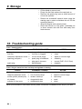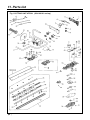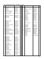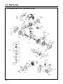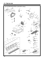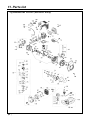
1
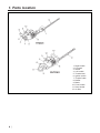
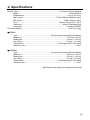
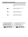
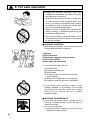
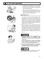
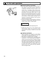
T1146-93110 (202)
OWNER / OPERATOR MANUAL
HEDGE-TRIMMERS
HT2301
CHT2301
WARNING
The engine exhaust from this product
contains chemicals known to the State
of California to cause cancer, birth
defects or other reproductive harm.
Thank you for purchasing a RedMax
product.
Before using our hedge-trimmers,
please read this manual carefully to
understand the proper use of your unit.
APPLICABLE SERIAL NUMBERS : 100101 and up
SAFETY FIRST
Instructions contained in warnings within this
manual marked with a
symbol concern
critical points which must be taken into
consideration to prevent possible serious
bodily injury, and for this reason you are
requested to read all such instructions
carefully and follow them without fail.
■ WARNINGS IN THE MANUAL
WARNING
This mark indicates instructions which must be
followed in order to prevent accidents which could
lead to serious bodily injury or death.
IMPORTANT
This mark indicates instructions which must be
followed, or it leads to mechanical failure,
breakdown, or damage.
NOTE
This mark indicates hints or directions useful in the
use of the product.
1.
2.
3.
4.
5.
6.
7.
8.
9.
10.
11.
CONTENTS
Parts location …………………………………4
Specifications …………………………………5
Warning labels on the machine ……………6
Symbols on the machine ……………………7
For safe operation ……………………………8
Fuel……………………………………………14
Operation ……………………………………16
Maintenance …………………………………20
Storage ………………………………………24
Troubleshooting guide ………………………24
Parts list ………………………………………25
1. Parts location
1.
2.
3.
4.
5.
6.
7.
8.
9.
10.
11.
12.
❲4 ❳
Right handle
Fuel tank
Starter
Left handle
Throttle lever
Ignition switch
Throttle Cable
Muffler
Blade
Front handle
Rear handle
Air filter
2. Specifications
Engine Type······················································································ Air-cooled 2-stroke gasoline
Model ········································································································ Zenoah G23LH
Displacement ······················································································· 1.4cu-in (22.5cm3)
Max. output ··································································· 0.7Hp (0.5kW)at 6500/min-1(rpm)
Idle speed························································································3200 ± 200/min-1(rpm)
Fuel ······················································································ Mixture (Gasoline 50 : Oil 1)
Carburetor ··················································································· Walbro Diaphragm type
Spark plug ···························································································· Champion RCJ6Y
Fuel tank capacity································································································ 20.3 fl.oz (0.6 )
■ HT2301
Type····································································· Reciprocating single-sided dual blades
Blade size ····························································································· 750 (mm) / 30 (in)
Blade pitch ··························································································· 41 (mm) / 1.62 (in)
Dry weight ··························································································· 5.4 (kg) / 11.4 (lbs)
Transmission ····································································· Centrifugal clutch, Cam-crank
Reduction ratio ········································································································· 4.417
■ CHT2301
Type ····································································· Reciprocating duble-sided dual blades
Blade size ····························································································· 600 (mm) / 24 (in)
Blade pitch ··························································································· 41 (mm) / 1.62 (in)
Dry weight ··························································································· 5.3 (kg) / 11.6 (lbs)
Transmission ····································································· Centrifugal clutch, Cam-crank
Reduction ratio ········································································································· 4.417
Specifications are subject to change without notice.
❲5 ❳
3. Warning labels on the machine
(1) Read owner's manual before operating this machine.
(2) Wear head, eye and ear protection.
IMPORTANT
If warning label peel off or become soiled and impossible to read, you should contact the dealer
from which you purchased the product to order new labels and affix them in the required
location(s).
WARNING
Never modify your machine.
We won't warrant the machine, if you use the remodeled hedge-trimmer or you don't
observe the proper usage written in the manual.
❲6 ❳
4. Symbols on the machine
For safe operation and maintenance, symbols are
carved in relief on the machine. According to these
indications, please be careful not to make a
mistake.
(a) The port to refuel the "MIX GASOLINE"
Position: FUEL TANK CAP
(b) The direction to close the choke
Position: AIR CLEANER COVER
(c) The direction to open the choke
Position: AIR CLEANER COVER
IMPORTANT ENGINE INFORMATION
THIS ENGINE CONFORMS TO U.S. EPA
PH1 FOR SMALL OFF-ROAD ENGINES.
ENGINE FAMILY : 1KZXS. 0254CD ; EM
ENGINE DISPLACEMENT : 22.5cc
REFER TO OWNER’S MANUMAL FOR MAINTENANCE SPECIFICATIONS AND ADJUSTMENTS.
RedMax
Made in Japan
INFORMATION IMPORTANTE CONCERNANT LE MOTEUR
Ce moteur conformc aux normcs U.S. EPA PH1 pour
les petits moteurs tout-terrain.
Type de moteur : 1KZXS. 0254CD ; EM
Cylindrée du moteur : 22.5 cc
Se référer au Manuel de l’utilisateur pour
les spécifications d’entretien et les réglages.
RedMax
Made in Japan
❲7 ❳
5. For safe operation
1. Read this manual carefully until you
completely understand and follow all safety
and operating instructions.
2. Keep this manual handy so that you may refer
to it later whenever any questions arise. Also
note, if you have any questions which cannot
be answered herein, contact the dealer from
whom you purchased the product.
3. Always be sure to include this manual when
selling, lending, or otherwise transferring the
ownership of this product.
4. Never allow children or anyone unable to fully
understand the directions given in the manual
to use the machine.
■ WORKING CONDITION
1. When using the product, you should wear proper
clothing and protective equipment.
(1) Helmet
(2) Ear protectors
(3) Protection goggles or face protector
(4) Thick work gloves
(5) Non-slip-sole work boots
2. And you should carry with you.
(1) Attached tools
(2) Properly reserved fuel
(3) Spare blade
(4) Things to notify your working area (rope,
warning signs)
(5) Whistle (for collaboration or emergency)
(6) Hatchet or saw (for removal of obstacles)
3. Do not wear loose clothing, jewelry, short
trousers, sandals, or go barefoot. Do not wear
anything which might be caught by a moving
part of the unit. Secure hair so it is above
shoulder length.
■ WORKING CIRCUMSTANCE
1. Never start the engine inside a closed room or
building. Exhaust gases contain dangerous
carbon monoxide.
2. Never use the product,
a. when the ground is slippery or when you can’t
maintain a steady posture.
❲8 ❳
5. For safe operation
b. At night, at times of heavy fog, or at any other
times when your field of vision might be
limited and it would be difficult to gain a clear
view of the working area.
c. During rain storms, during lightning storms, at
times of strong or gale-force winds, or at any
other times when weather conditions might
make it unsafe to use the product.
■ WORKING PLAN
1. You should never use the product when under
the influence of alcohol, when suffering from
exhaustion or lack of sleep, when suffering from
drowsiness as a result of having taken cold
medicine or at any other time when a possibility
exists that your judgment might be impaired or
that you might not be able to operate the product
properly and in a safe manner.
2. When planning your work schedule, allow plenty
of time to rest. Limit the amount of time over
which the product is to be used continuously to
somewhere around 30~40 minutes per session,
and take 10~20 minutes of rest between work
sessions. Also try to keep the total amount of
work performed in a single day under 2 hours or
less.
WARNING
1. If you don’t observe the working time, or
working manner (See ■ USING THE
PRODUCT), Repetitive Stress Injury(RSI)
could occur.
If you feel discomfort, redness and swelling
of your fingers or any other part of your
body, see a doctor before getting worse.
2. To avoid noise complaints, in general,
operate product between 8a.m. and 5p.m. on
weekdays and 9a.m. to 5p.m. weekends.
NOTE
Check and follow the local regulations as to sound
level and hours of operations for the product.
❲9 ❳
5. For safe operation
■ BEFORE STARTING THE ENGINE
1. The area within a perimeter of 50 feet (15m) of
the person using the product should be
considered a hazardous area into which no one
should enter. If necessary yellow warning rope,
warning signs should be placed around the
perimeter of the area. When work is to be
performed simultaneously by two or more
persons, care should also be taken to constantly
look around or otherwise check for the presence
and locations of other people working so as to
maintain a distance between each person
sufficient to ensure safety.
2. Check the condition of working area to avoid any
accident by hitting hidden obstacles such as
stumps, stones, cans, or broken grass.
IMPORTANT
Remove any obstacle before beginning work.
3. Inspect the entire unit for loose fasteners and
fuel leakage. Make sure that the cutting
attachment is properly installed and securely
fastened.
■ STARTING THE ENGINE
1. Keep bystanders and animals at least 50feet
(15m) away from the operating point. If you are
approached, immediately stop the engine.
2. The product is equipped with a centrifugal clutch
mechanism, so the cutting attachment begins to
rotate as soon as the engine is started by putting
the throttle into the start position. When starting
the engine, place the product onto the ground in
a flat clear area and hold it firmly in place so as
to ensure that neither the cutting part nor the
throttle come into contact with any obstacle
when the engine starts.
❲ 10 ❳
5. For safe operation
WARNING
Never place the throttle into the high speed
position when starting the engine.
3. After starting the engine, check to make sure
that the cutting attachment stops rotating when
the throttle is moved fully back to its original
position. If it continues to rotate even after the
throttle has been moved fully back, turn off the
engine and take the unit to your authorized Red
Max servicing dealer for repair.
■ USING THE PRODUCT
IMPORTANT
Cut only materials recommended by the
manufacturer. And use only for tasks explained
in the manual.
1. Grip the handles firmly with both hands using
your whole hand. Place your feet slightly apart
(slightly further apart than the width of your
shoulders) so that your weight is distributed
evenly across both legs, and always be sure to
maintain a steady, even posture while working.
2. Maintain the speed of the engine at the level
required to perform cutting work, and never raise
the speed of the engine above the level
necessary.
3. If the unit start to shake or vibrate, turn off the
engine and check the whole unit. Do not use it
until the trouble has been properly corrected.
4. Keep all parts of your body away from rotating
cutting attachment and hot surfaces.
5. Never touch the muffler, spark plug, or other
metallic parts of the engine while the engine is in
operation or immediately after shutting down the
engine. Doing so could result in serious burns or
electrical shock.
❲ 11 ❳
5. For safe operation
• IF SOMEONE COMES
1. Guard against hazardous situations at all times.
Warn adults to keep pets and children away
from the area. Be careful if you are approached.
Injury may result from flying debris.
2. If someone calls out or otherwise interrupts you
while working, always be sure to turn off the
engine before turning around.
■ MAINTENANCE
1. In order to maintain your product in proper
working order, perform the maintenance and
checking operations described in the manual at
regular intervals.
2. Always be sure to turn off the engine before
performing any maintenance or checking
procedures.
WARNING
The metallic parts reach high temperatures
immediately after stopping the engine.
3. When replacing the cutting attachment or any
other part, or when replacing the oil or any
lubricant, always be sure to use only RedMax
products or products which have been
certified by RedMax for use with the RedMax
product.
4. In the event that any part must be replaced or
any maintenance or repair work not described in
this manual must be performed, please contact a
representative from the store nearest RedMax
authorized servicing dealer for assistance.
5. Do not use any accessory or attachment other
than those bearing the RedMax mark and
recommended for the unit.
6. Under no circumstances should you ever take
apart the product or alter it in any way. Doing so
might result in the product becoming damaged
during operation or the product becoming unable
to operate properly.
❲ 12 ❳
5. For safe operation
■ HANDLING FUEL
1. The engine of the RedMax product is designed
to run on a mixed fuel which contains highly
flammable gasoline. Never store cans of fuel or
refill the tank of the unit in any place where there
is a boiler, stove, wood fire, electrical sparks,
welding sparks, or any other source of heat or
fire which might ignite the fuel.
2. Never smoke while operating the unit or refilling
its fuel tank.
3. When refilling the tank, always turn off the
engine and allow it to cool down. Take a careful
look around to make sure that there are no
sparks or open flames anywhere nearby before
refueling.
4. Wipe spilled fuel completely using a dry rag if
any fuel spillage occurs during refueling.
5. After refueling, screw the fuel cap back tightly
onto the fuel tank and then carry the unit to a
spot 10feet (3m) or more away from where it
was refueled before turning on the engine.
■ TRANSPORTATION
1. When hand-carrying the product, cover over the
cutting part if necessary, lift up the product and
carry it paying attention to the blade.
2. Never transport the product over rough roads
over long distances by vehicle without removing
all fuel from the fuel tank. If doing so, fuel might
leak from the tank during transport.
❲ 13 ❳
6. Fuel
WARNING
• Gasoline is very flammable. Avoid smoking
or bringing any flame or sparks near fuel.
Make sure to stop the engine and allow it
cool before refueling the unit. Select outdoor
bare ground for fueling and move at least
3m(10ft) away from the fueling point before
starting the engine.
• The RedMax engines are lubricated by oil
specially formulated for air-cooled 2-cycle
gasoline engine use. If RedMax oil is not
available, use an anti-oxidant added quality oil
expressly labeled for air-cooled 2-cycle engine
use. (JASO FC GRADE OIL or ISO EGC
GRADE)
RECOMMENDED MIXING RATIO
GASOLINE 50:OIL 1
50:1 MIXING CHART
GASOLINE gal. 1
2
3
4
5
2-CYCLE OIL fl.oz 2.6 5.2 7.8 10.4 13
GASOLINE liter
2-CYCLE OIL ml
1
20
2
40
3
60
4
80
5
100
• Exhaust emission are controlled by the
fundamental engine parameters and
components(eq., carburation, ignition timing
and port timing) without addition of any
major hardware or the introduction of an
inert material during combustion.
• These engines are certified to operate on
unleaded gasoline.
• Make sure to use gasoline with a minimum
octane number of 90 ROZ(USA/Canada : pump
octane min.87)
• Unleaded gasoline is recommended to reduce
the contamination of the air for the sake of your
health and the environment.
• Poor quality gasolines or oils may damage
sealing rings, fuel lines or fuel tank of the
engine.
■ HOW TO MIX FUEL
1. Measure out the quantities of gasoline and oil to
be mixed.
2. Put some of the gasoline into a clean, approved
fuel container.
3. Pour in all of the oil and agitate well.
4. Pour in the rest of gasoline and agitate again for
at least one minute.
5. Put a clear indication on the outside of the
❲ 14 ❳
6. Fuel
container to avoid mixing up with gasoline or
other containers.
6. Indicate the contents on outside of container for
easy identification.
■ FUELING THE UNIT
1. Untwist and remove the fuel cap. Rest the cap
on a dustless place.
2. Put fuel into the fuel tank to 80% of the full
capacity.
3. Fasten the fuel cap securely and wipe up any
fuel spillage around the unit.
WARNING
1. Select bare ground for fueling.
2. Move at least 10 feet (3 meters) away from the
fueling point before starting the engine.
3. Stop the engine before refueling the unit.
FOR YOUR ENGINE LIFE, AVOID;
1. FUEL WITH NO OIL(RAW GASOLINE) – It will
cause severe damage to the internal engine
parts very quickly.
2. GASOHOL – It can cause deterioration of rubber
and/or plastic parts and disruption of engine
lubrication.
3. OIL FOR 4-CYCLE ENGINE USE or WATER
COOLED 2-CYCLE ENGINE USE – It can
cause spark plug fouling, exhaust port blocking,
or piston ring sticking.
4. Mixed fuels which have been left unused for
a period of one month or more may clog the
carburetor and result in the engine failing to
operate properly.
❲ 15 ❳
7. Operation
■ STARTING ENGINE
WARNING
The cutting head will start rotating upon the
engine starts.
OP1
OP2
1. Rest the unit on a flat, firm place. Keep the
cutting head off the ground and clear of
surrounding objects as it will start rotating upon
starting of the engine.
2. Push the primer pump several times until
overflown fuel flows out in the clear tube.
3. Move the choke lever to the closed position.
(OP1)
4. Set the ignition switch to the “START” position.
(OP2)
(2)
(1) choke lever
(2) ignition switch
(3) throttle lever
(3)
OP3
[HT2301]
5. Holding the hedge-trimmer down, pull the
starting rope slowly until you meet resistance
(OP3). Then operatel hard several times, and
when the engine starts, wait for about 10
seconds and then pull the throttle lever (OP2(3)),
the choke lever (OP1(1)) will return automatically
to the original “OPEN” position.
WARNING
Use the semi-acceleration device only in the
phase of starting the engine.
[CHT2301]
IMPORTANT
• Avoid pulling the rope to its end or returning it by
releasing the knob. Such actions can cause
starter failures.
❲ 16 ❳
7. Operation
NOTE
1. When restarting the engine immediately after
stopping it, leave the choke open.
2. Overchoking can make the engine hard to start
due to excess fuel. When the engine failed to
start after several attempts, open the choke and
repeat pulling the rope, or remove the spark plug
and dry it.
■ STOPPING ENGINE (OP2)
1. Release the throttle lever and run the engine for
a half minute.
2. Shift the ignition switch to the “STOP” position.
IMPORTANT
• Except for an emergency, avoid stopping the
engine while pulling the throttle lever.
IMPORTANT
RUNNING IN THE ENGINE
• During the first 20 working hours, do not use the
hedge-trimmer at maximum power for long
periods.
OP4
■ ADJUSTING IDLING SPEED
• Before adjusting the carburetor, clean the air
filter and warm up the engine. (OP4)
(1) air filter
• Idle screw is adjusted in order to ensure a good
safety margin between idle running and clutch
engagement. (OP5)
OP5
(1) Idle screw
WARNING
With the engine idling (3200 rpm), the blade
should not rotate. We recommend that you
have the dealer or an authorised mechanic
carry out any carburetor adjustments.
❲ 17 ❳
7. Operation
WARNING
• Weather conditions and altitude may effect
carburation.
• Do not allow anyone to stay close to the
hedge-trimmer while working or while
adjusting the carburetor.
■ HOW TO USE
HANDLE (CHT2301 only)
To reduce fatigue when trimming hedges, the
handle can be swivelled through 90° to the left or
right. (OP6, OP7).
Do not press the throttle during this operation!
OP6
(2)
90°
(1)
90°
OP7
Proceed as follows:
1. Free the handle by pressing the locking lever;
(OP6)
2. Turn the handle until the locking lever clicks into
place;
3. When the handle is locked in its new position,
you can apply the throttle again.
(1) handle
(2) locking lever
You can swivel the handle even with the engine
idling because the hedge-trimmer is equipped with
a blade brake that maintains the blades at a
standstill.
❲ 18 ❳
7. Operation
OP8
HEDGE TRIMMING TECHNIQUES
Trim sides of a hedge first, and then the top.
Vertical cut:
• With the single-sided blade hedge-trimmer,
model HT2301 always cut from the bottom up
(OP8). With the 2-sided blade model CHT2301
use an arcing cut from the bottom upwards, then
downwards to use both sides of the blades
(OP9).
OP9
Horizontal cut:
• In order to get the best cutting results, slightly tilt
the blade (5÷10°) towards the cutting direction
(OP10, OP11).
Cut slowly, specially with thick hedges.
WARNING
OP10
Always follow the safety precautions.
The hedge-trimmer must only be used to trim
hedges or small bushes. It is forbidden to cut
other types of material. Do not use the hedgetrimmer as a lever to lift, move or break objects,
nor lock it on fixed supports. It is forbidden to
apply tools or applications that are not the
ones indicated by the manufacturer onto the
hedge-trimmer’s power take-off. Do not use it
for pruning trees or cutting grass.
OP11
❲ 19 ❳
8. Maintenance
ENGINE
■ MAINTENANCE CHART
every every every
25
50
100
before hours hours hours note
use after after after
system/compornent
procedure
fuel leaks, fuel spillage
wipe out
✔
fuel tank, air filter, fuel filter
inspect/clean
✔
idle adjusting screw
spark plug
see ■ADJUSTING
IDLING SPEED (p.17)
✔
replace carburetor
✔
if necessary
clean and readjust
plug gap
SHAFT
cutting parts
replace if
something's wrong
✔
✔
✔
✔
gear case
grease
screws/nuts/bolts
tighten/replace
✔
blade guard
make sure to attach
✔
❲ 20 ❳
replace, if necessary
✔
muffler, spark arrester, cylinder exhaust port clean
check operation
GAP: .025in(0.6~0.7mm)
✔
cylinder fins, intake air cooling vent clean
throttle lever, ignition switch
replace, if necessary
✔
not adjusting screws
8. Maintenance
WARNING
• Make sure that the engine has stopped and is
cool before performing any service to the
machine. Contact with moving cutting head
or hot muffler may result in a personal injury.
MA1
■ AIR FILTER
• The air filter, if clogged, will reduce the engine
performance. Check and clean the filter element
in warm, soapy water as required. Dry
completely before installing. If the element is
broken or shrunk, replace with a new one. (MA1)
(1) air filter
■ FUEL FILTER
• When the engine runs short of fuel supply, check
the fuel cap and the fuel filter for blockage.
(MA2)
MA2
(1) fuel filter
(1)
■ SPARK PLUG
• Starting failure and mis-firing are often caused
by a fouled spark plug. Clean the spark plug and
check that the plug gap is in the correct range.
For a replacement plug, use the correct type
specified by RedMax. (MA3)
MA3
• REPLACEMENT PLUG IS A CHAMPION
RCJ6Y OR THE EQUIVALENT, SUCH AS
BOSCH WR8E OR NGK BR6S.
.025 in
0.655mm
IMPORTANT
• Note that using any spark plug other than those
designated may result in the engine failing to
operate properly or in the engine becoming
overheated and damaged.
• To install the spark plug, first turn the plug until it
is finger tight, then tighten it a quarter turn more
with a socket wrench.
TIGHTENING TORQUE:
87~104 in-lbs
(9.8~11.8 N.m.)
❲ 21 ❳
8. Maintenance
■ MUFFLER
WARNING
• Inspect periodically, the muffler for loose
fasteners, any damage or corrosion. If any sign
of exhaust leakage is found, stop using the
machine and have it repaired immediately.
• Note that failing to do so may result in the
engine catching on fire.
■ INTAKE AIR COOLING VENT
WARNING
MA4
• Never touch the cylinder, muffler, or spark
plugs with your bare hands immediately after
stopping the engine. The engine can
become very hot when in operation, and
doing so could result in severe burns.
• Clean the cylinder fins with compressed air or a
brush. (MA4)
(1) cylinder fin
(2) intake air cooling vent (back)
IMPORTANT
• If waste gets stuck and causes blockage around
the intake air cooling vent or between the
cylinder fins, it may cause the engine to
overheat, and that in turn may cause mechanical
failure on the part of the hedge-trimmer.
❲ 22 ❳
8. Maintenance
MA5
■ BLADES
Oil blades each gas tank filling (MA5).
WARNING
• Make sure that the blade bolts are well
tightened.
• The blade assembly is designed to
automatically compensate for any play
between the blades.
MA6
■ SHARPENING (MA6)
Always keep the file or sharpener at an angle of
45° to the blade, and:
• Always grind in the direction of the cutting edge;
• Note: files cut only in one direction; lift the file
from the blade when returning to start a new
pass;
• Remove all burr from the edge of the blade with
a slip stone;
• Remove as little material as possible;
• Before refitting the sharpened blades, remove
filings and then apply grease.
Do not try to sharpen a damaged blade: change it
or take it to a Service dealer.
MA7
■ REDUCTION GEARBOX
Refill gear housing every 20 working hours (MA7).
Use greese pump. Feed greese until it comes out
of the base of blades.
■ PROCEDURES TO BE PERFORMED AFTER
EVERY 100 HOURS OF USE
1. Tighten all screws, bolts, and fittings.
2. Check to see if any oil or grease has worked its
way in between the clutch lining and drum, and if
it has wipe it away using oil-free, lead-free
gasoline.
❲ 23 ❳
9. Storage
• Oil the blade to prevent rust.
• Empty the fuel tank and put the cap back on.
• Remove the spark plug, pour a small amount of
oil into the cylinder.
• Rotate the crankshaft several times using the
starting rope in order to distribute the oil. Put the
spark plug back in.
• Wrap the engine with a plastic sheet.
• Store the trimmer in a dry place, preferably not
in direct contact with the floor and away from
heat sources.
10. Troubleshooting guide
Case 1. Starting failure
CHECK
fuel tank
fuel filter
carburetor adjustment screw
sparking (no spark)
spark plug
➞
➞
➞
➞
➞
➞
PROBABLE CAUSES
incorrect fuel
fuel filter is clogged
out of normal range
spark plug is fouled/wet
plug gap is incorrect
disconnected
➞
➞
➞
➞
➞
➞
ACTION
drain it and with correct fuel
clean
adjust to normal range
clean/dry
correct (GAP: 0.6~0.7mm)
retighten
Case 2. Engine starts but does not keep running/Hard re-starting.
CHECK
fuel tank
carburetor adjustment screw
muffler,cylinder (exhaust port)
air cleaner
cylinder fin, fan cover
➞
➞
➞
➞
➞
PROBABLE CAUSES
incorrect fuel or staled fuel
out of normal range
carbon is built-up
clogged with dust
clogged with dust
➞
➞
➞
➞
➞
ACTION
drain it and with correct fuel
adjust to normal range
wipe away
wash
clean
When your unit seems to need further service, please consult with our RedMax service shop in your area.
❲ 24 ❳
11. Parts list
HEDGE-TRIMMERS
HT2301
CHT2301
NOTE :
1. Use KOMATSU ZENOAH genuine parts as specified in the parts list for repair and/or
replacement.
2. KOMATSU ZENOAH does not warrant the machines, which have been damaged by the
use of any parts other than those specified by the company.
3. When placing parts orders for repair and/or replacement, check if the model name and the
serial number are applicable to those specified in the parts list, then use parts number
described in the parts list.
4. The contents described in the parts list may change due to improvement.
5. The parts for the machine shall be supplied seven (7) years after the machine is
discontinued. [It is possible that some specific parts may be subject to change of their
delivery term and list price within the limit of ten (7) years after the machine is
discontinued. It is also possible that some parts may be available even after the limit of
seven (7) years.]
May 2001
APPLICABLE SERIAL NUMBERS : 100101 and up
❲ 25 ❳
11. Parts list
Fig.1 CUTTING UNIT HT2301 (S/N 100101 and up)
❲ 26 ❳
Fig.1 CUTTING UNIT HT2301 (S/N 100101 and up)
Key#
1
2
3
4
5
6
7
Description
Part Number
Q'ty
Key#
Description
47
48
49
50
51
52
53
54
55
56
57
58
59
60
BAND LEVER
PIN
THROTTLE CABLE
COLLAR
SPRING
SNAP RING
RE GEAR BODY
COLLAR
COLLAR
SCREW
WASHER
WASHER
BUSHING
BUSHING
58040070
3033019
58040235
58040111
58040091
3025022
58042021A
58040203
58040114
3960069
3918003
3918010
61070015
61040020
1
1
1
2
1
1
1
1
4
4
4
4
4
1
62
GEAR COVER
58040189
1
64
65
66
67
68
69
70
71
72
73
74
SUPPORT
BEARING
BEARING
UPPER BLADE
LOWER BLADE
SPACER
GREASE NIPPLE
SCREW
LEVER
COVER
SCREW
58040199
58040176
58040180
58040046A
58040047A
61070015
58040180
3801057
58040074
T1146-92110
T1146-92120
1
1
1
1
1
4
1
2
1
1
1
SCREW
HANDLE
NUT
PLATE
SWITCH GUARD
CLUTCH DRUM
DRIVE GEAR
3960067
58040143
3980014
58040057
2317013
58040238
58040239
5
1
4
2
1
1
1
9
10
11
THROTTLE LEVER
SPRING
SCREW
58040084
58040136
3960082B
1
1
16
14
15
16
17
18
19
20
21
22
23
24
25
26
27
REAR HANDLE
LEVER
SWITCH
CABLE
THROTTLE CABLE
COLLAR
GASKET
SCREW
REAR HANDLE
DEFLECTOR (OPTIONAL)
SCREW
COVER
UPPER SUPPORT
LOWER SUPPORT
58040201
58040085
2317021
58040207
58040116
58040204
58040177
3960067
58040200
58040150
012000028
58040196A
58040049
58040050
1
1
1
1
1
2
1
2
1
1
2
1
1
1
29
30
31
32
33
34
35
36
37
38
39
40
41
42
43
44
45
46
SCREW
BEARING
GASKET
SUPPORT
DRIVEN GEAR
COVER
ROLLER
CON-ROD
BLADE GUARD
LEVER
SCREW
HANDLE
GUARD
BLADES ASSY
SPACER
BRAKE CAM
LEVER
BRAKE BAND
3979021
3035019
58040106
58040202
58040230
58040188
58040072
58040227
58040122
58040161
3960073
58040197
58040198
58040094A
58040051
58040073
58040095
58040017
4
1
1
1
1
1
1
2
1
1
13
2
2
1
7
1
1
1
Part Number
Q'ty
❲ 27 ❳
11. Parts list
Fig.2 ENGINE UNIT HT2301 (S/N 100101 and up)
❲ 28 ❳
Fig.2 ENGINE UNIT HT2301 (S/N 100101 and up)
Key#
Description
Part Number Q'ty
1
2
3
4
5
6
7
8
Cylinder
Gasket, base
Bolt, M5x22
Insulator
Gasket, insulator
Gasket, carb
Screw, M5x20
Muffler ass'y
5602-12110
5500-12213
1850-12130
5500-13163
5500-13121
5500-13131
0263-90520
T1146-15110
1
1
2
1
1
1
2
1
11
12
13
14
15
16
17
18
19
20
21
Bolt, M5x50
Gasket, muffler
Plate, muffler
Screw, M4x16
Crancase comp.
Gasket, case
Bearing
Oil seal
Oil seal
Snap ring
Bolt, M5x30
01252-30550
5910-15211
5600-15220
0263-90416
T1146-21100
5500-21141
06030-06001
2169-21210
1850-21220
04065-02812
01252-30530
2
1
1
1
1
1
2
1
1
1
4
24
25
26
27
28
29
30
31
32
33
34
35
36
Piston
Ring, piston
Pin, piston
Snap ring
Bearing
Washer
Crankshaft comp.
Nut
Key
Shoe-c
• Shoe
• Boss
• Spring
5600-41111
1100-41210
1101-41310
1260-41320
5500-41410
1101-41340
5500-42001
1650-43230
1000-43240
T1146-51100
T1501-51110
T1146-51120
T1501-51220
1
2
1
2
1
2
1
1
1
1
2
1
2
42
43
44
45
46
47
48
49
50
51
52
53
54
55
56
57
58
59
60
61
62
Rotor
Coil ass'y
• Cord
• Cap
Cap, spark plug
Spring
Grommet
Spacer
Bolt, M4x25
Recoil ass'y
• Case, recoil
• Spring, Spiral
• Reel
• Ratchet
• Spring
• Screw
• Retainer
• Washer
• Rope
• Knob
Screw
5601-71110
5600-71200
5600-71220
2616-71320
5500-72110
1900-72120
5500-72130
1260-71261
3310-72150
5990-75101
5990-75110
5990-75120
5990-75130
5990-75140
5990-75151
5990-75270
5990-75160
5990-75170
1861-75180
1490-75181
0263-90412
1
1
1
1
1
1
1
2
2
1
1
1
1
1
1
1
1
1
1
1
4
Note
Key#
Description
Part Number Q'ty
63
64
65
66
67
68
69
70
71
72
73
74
75
76
77
78
79
80
81
82
83
84
85
86
87
88
89
90
91
92
93
94
95
96
97
98
99
100
101
102
103
104
105
Bracket
Gasket, carburetor
Carburetor ass'y
• Screw
• Ring
• Swivel
• Valve ass'y
• O-ring
• Jet #37
• Rebuilt Kit
• • Body ass’y
• • • Screen
• • Gasket Kit
• • • Diaphragm, pump
• • • Gasket, pump
• • • Diaphragm
• • • Gasket, diaphragm
• Body, purge
• Pump, priming
• Cover, pump
• Screw
Screw
Label, recoil
Cap
Screw, M5x60
Clip
Body ass'y
• Sleeve
• Plate, choke
• Lever, choke
• Screw
Element
Cover ass'y
• Knob
Cover, fan
Screw, M5x20
Cover, engine
Screw, M5x12
Screw
Spark plug
Grommet
Cord comp.
Clamp
5628-83221
5500-13131
5602-81001
5850-81110
1751-81130
1881-81140
–––––––––
1751-81240
5628-81250
5602-06030
1850-81450
–––––––––
5602-06020
–––––––––
–––––––––
–––––––––
–––––––––
1850-81490
1751-81510
1850-81520
1850-81530
T1146-85510
T1146-91120
1601-81810
0263-90560
1950-86120
T1600-82100
1970-82190
T1600-82130
T1600-82140
2630-33610
5500-82171
5600-82203
5500-82221
5600-31110
0263-90520
T1146-32100
1850-32160
1900-31410
5602-73110
1852-72121
T1146-73200
1140-72231
1
1
1
2
1
1
1
1
1
1
1
–
1
–
–
–
–
1
1
1
4
3
1
1
2
1
1
2
1
1
1
1
1
1
1
4
1
1
1
1
1
1
1
107
108
109
110
111
112
113
114
115
116
117
Tank ass'y
• Cap ass'y
• • Packing
• • Holder
• • Filter
• • Stopper
• Pipe comp.
• Filter ass'y
• Clip
Clip
Screw
T1146-85000
T1015-85202
4500-85220
4500-85300
5601-85260
4820-85260
4810-85300
5500-85400
1260-85460
1950-86120
T1501-11120
1
1
1
1
1
1
1
1
1
1
4
Note
WYL-55
RCJ6Y
❲ 29 ❳
11. Parts list
Fig.3 CUTTING UNIT CHT2301 (S/N 100101 and up)
❲ 30 ❳
Fig.3 CUTTING UNIT CHT2301 (S/N 100101 and up)
Key#
Description
1
2
3
4
5
6
7
8
9
10
11
12
13
14
15
16
17
18
SCREW
FRONT HANDLE
NUT
PLATE
SWITCH GUARD
CLUTCH DRUM
DRIVE GEAR
SPRING
THROTTLE LEVER
SPRING
SCREW
SCREW
CAP
HANDLE
LEVER
SWITCH
SWITCH CABLE
THROTTLE CABLE
20
21
22
23
24
25
26
27
29
30
31
32
33
34
35
36
37
38
39
40
41
42
43
44
45
46
Part Number
Q'ty
Key#
Description
3960067
58040185A
3980014
58040057
2317013
58040238
58040239
58040080
58040084
58040136
3960057
3960073
61040071
58040181
58040085
2317021
58040175
58040087
7
1
4
2
1
1
1
2
1
1
2
5
1
1
1
1
1
1
47
48
49
50
51
52
53
54
55
56
57
58
59
60
61
62
63
64
BAND LEVER
PIN
THROTTLE CABLE
LEVER
SPRING
SNAP RING
GEAR BODY
GEAR COVER
SCREW
BEARING
BEARING
BLADE
SCREW
WASHER
GREASE NIPPLE
SPACER
SCREW
LEVER
GASKET
SCREW
REAR HANDLE
DEFLECTOR
BLADE SUPPORT
COVER
ROD
BLADE GUIDE
58040177
3960067
58040183
58040184
58040191
58040196A
58040090
58040045
1
2
1
1
1
1
1
1
SCREW
BEARING
GASKET
SUPPORT
DRIVEN GEAR
COVER
ROLLER
ROD
BLADE GUARD
LEVER
SCREW
WASHER
SPRING
BLADES ASSY
SPACER
BRAKE CAM
LEVER
BRAKE BAND
3979021
3035019
58040077
58040187
58040230
58040188
58040072
58040227
58040092
58040088
58040074
3918003
58040091
58040205A
58040051
58040073
58040095
58040017
4
1
1
1
1
1
1
2
1
1
11
2
1
1
6
1
1
1
Part Number
58040070
3033019
58040235
58040089
58040079
3025022
58042021A
58040189
3960082B
58040176
58040182
58040043A
3960069
3918003
58040180
3027015
3960070
58040074
Q'ty
1
1
1
1
2
1
1
1
16
1
1
2
1
1
1
1
2
1
❲ 31 ❳
11. Parts list
Fig.4 ENGINE UNIT CHT2301 (S/N 100101 and up)
❲ 32 ❳
Fig.4 ENGINE UNIT CHT2301 (S/N 100101 and up)
Key#
Description
Part Number Q'ty
1
2
3
4
5
6
7
8
Cylinder
Gasket, base
Bolt, M5x22
Insulator
Gasket, insulator
Gasket, carb
Screw, M5x20
Muffler ass'y
5602-12110
5500-12213
1850-12130
5500-13163
5500-13121
5500-13131
0263-90520
T1155-15110
1
1
2
1
1
1
2
1
11
12
13
14
15
16
17
18
19
20
21
Bolt, M5x50
Gasket, muffler
Plate, muffler
Screw, M4x16
Crancase comp.
Gasket, case
Bearing
Oil seal
Oil seal
Snap ring
Bolt, M5x30
01252-30550
5910-15211
5600-15220
0263-90416
T1146-21100
5500-21141
06030-06001
2169-21210
1850-21220
04065-02812
01252-30530
2
1
1
1
1
1
2
1
1
1
4
24
25
26
27
28
29
30
31
32
33
34
35
36
Piston
Ring, piston
Pin, piston
Snap ring
Bearing
Washer
Crankshaft comp.
Nut
Key
Shoe-c
• Shoe
• Boss
• Spring
5600-41111
1100-41210
1101-41310
1260-41320
5500-41410
1101-41340
5500-42001
1650-43230
1000-43240
T1146-51100
T1501-51110
T1146-51120
T1501-51220
1
2
1
2
1
2
1
1
1
1
2
1
2
42
43
44
45
46
47
48
49
50
51
52
53
54
55
56
57
58
59
60
61
62
Rotor
Coil ass'y
• Cord
• Cap
Cap, spark plug
Spring
Grommet
Spacer
Bolt, M4x25
Recoil ass'y
• Case, recoil
• Spring, Spiral
• Reel
• Ratchet
• Spring
• Screw
• Retainer
• Washer
• Rope
• Knob
Screw
5601-71110
5600-71200
5600-71220
2616-71320
5500-72110
1900-72120
5500-72130
1260-71261
3310-72150
5990-75101
5990-75110
5990-75120
5990-75130
5990-75140
5990-75151
5990-75270
5990-75160
5990-75170
1861-75180
1490-75181
0263-90412
1
1
1
1
1
1
1
2
2
1
1
1
1
1
1
1
1
1
1
1
4
Note
Key#
Description
Part Number Q'ty
63
64
65
66
67
68
69
70
71
72
73
74
75
76
77
78
79
80
81
82
83
84
85
86
87
88
89
90
91
92
93
94
95
96
97
98
99
100
101
102
103
104
105
Bracket
Gasket, carburetor
Carburetor ass'y
• Screw
• Ring
• Swivel
• Valve ass'y
• O-ring
• Jet #37
• Rebuilt Kit
• • Body ass’y
• • • Screen
• • Gasket Kit
• • • Diaphragm, pump
• • • Gasket, pump
• • • Diaphragm
• • • Gasket, diaphragm
• Body, purge
• Pump, priming
• Cover, pump
• Screw
Screw
Label, recoil
Cap
Screw, M5x60
Clip
Body ass'y
• Sleeve
• Plate,choke
• Lever, choke
• Screw
Element
Cover ass'y
• Knob
Cover, fan
Screw, M5x20
Cover, engine
Screw, M5x12
Screw
Spark plug
Grommet
Cord comp.
Clamp
5628-83221
5500-13131
5602-81001
5850-81110
1751-81130
1881-81140
–––––––––
1751-81240
5628-81250
5602-06030
1850-81450
–––––––––
5602-06020
–––––––––
–––––––––
–––––––––
–––––––––
1850-81490
1751-81510
1850-81520
1850-81530
T1146-85510
T1155-91120
1601-81810
0263-90560
1950-86120
T1600-82100
1970-82190
T1600-82130
T1600-82140
2630-33610
5500-82171
5600-82203
5500-82221
5600-31110
0263-90520
T1146-32100
1850-32160
1900-31410
5602-73110
1852-72121
T1146-73200
1140-72231
1
1
1
2
1
1
1
1
1
1
1
–
1
–
–
–
–
1
1
1
4
3
1
1
2
1
1
2
1
1
1
1
1
1
1
4
1
1
1
1
1
1
1
108
109
110
111
112
113
114
115
116
117
118
Tank ass'y
• Cap ass'y
• • Packing
• • Holder
• • Filter
• • Stopper
• Pipe comp.
• Filter ass'y
• Clip
Clip
Screw
T1146-85000
T1015-85202
4500-85220
4500-85300
5601-85260
4820-85260
4810-85300
5500-85400
1260-85460
1950-86120
T1501-11120
1
1
1
1
1
1
1
1
1
1
4
Note
WYL-55
RCJ6Y
❲ 33 ❳
CALIFORNIA EMISSION CONTROL WARRANTY STATEMENT
YOUR WARRANTY RIGHTS AND OBLIGATIONS
The California Air Resources Board and KOMATSU ZENOAH are pleased to explain the
emission control system warranty on your 1995 and later small off-road engine. In California,
new small off-road engines must be designed, built and equipped to meet the state’s stringent
anti-smog standards. KOMATSU ZENOAH must warrant the emission control system on your
small off-road engine for the periods of time listed below provided there has been no abuse,
neglect or improper maintenance of your small off-road engine.
Your emission control system may include parts such as the carburetor and the ignition system.
Where a warrantable condition exists, KOMATSU ZENOAH will repair your small off-road engine
at no cost to you including diagnosis, parts and labor.
Manufacturer’s warranty coverage:
The 1995 and later small off-road engines are warranted for two years. If any emissionrelated part on your engine is defective, the part will be repaired or replaced by
KOMATSU ZENOAH.
Owner’s warranty responsibilities:
– As the small off-road engine owner, you are responsible for the performance of the
required maintenance listed in your owner’s manual. KOMATSU ZENOAH
recommends that you retain all receipts covering maintenance on your small off-road
engine, but KOMATSU ZENOAH can not deny warranty solely for the lack of receipts or
for your failure to ensure the performance of all scheduled maintenance.
– As the small off-road engine owner, you should be aware, however, that KOMATSU
ZENOAH may deny you warranty coverage if your small off-road engine or a part has
failed due to abuse, neglect, improper maintenance or unapproved modification.
– You are responsible for presenting your small off-road engine to a KOMATSU ZENOAH
distribution center as soon as a problem exists. The warranty repairs should be
completed in e reasonable amount of time, not to exceed 30 days.
If you have any questions regarding your warranty rights and responsibilities, you should
contact KOMATSU ZENOAH AMERICA INC. at (770)-381-5147 or you can write to
KOMATSU ZENOAH AMERICA INC.
4344 Shackleford Road Suite 500
Norcross, Georgia 30093
RedMax 2-YEAR LIMITED WARRANTY
EMISSION-RELATED PARTS, FOR TWO (2) YEARS FROM THE DATE OF ORIGINAL DELIVERY, KOMATSU ZENOAH
AMERICA INC. (THE COMPANY), THROUGH ANY RedMax DEALER, WILL REPAIR OR REPLACE, FREE OF CHARGE,
FOR THE ORIGINAL AND EACH SUBSEQUENT PURCHASER, ANY PART OR PARTS FOUND TO BE DEFECTIVE IN
MATERIAL AND/OR WORKMANSHIP. EMISSION-RELATED PARTS ARE:
THE CARBURETOR ASSY, COIL ASSY, ROTOR, SPARKPLUG,
AIR FILTER, FUEL FILTER, INTAKE MANIFOLD, AND THE GASKETS
ALL OTHER PARTS EXCEPT ABOVE PARTS, FOR TWO (2) YEARS OF HOME USE [ ONE (1) YEAR FOR ANY OTHER
USE ] FROM THE DATE OF ORIGINAL ANY DELIVERY, THE COMPANY. THROUGH ANY RedMax DEALER, WILL REPAIR
OR REPLACE, FREE OF CHARGE, FOR THE ORIGINAL PURCHASER, ANY PART OF PARTS FOUND TO BE DEFECTIVE
IN MATERIAL AND/OR WORKMANSHIP. THIS IS THE EXCLUSIVE REMEDY.
THE PURCHASER SHALL BEAR COSTS OF TRANSPORTING THE UNIT TO AND FROM THE RedMax DEALER.
THE PURCHASER SHALL NOT BE CHARGED FOR DIAGNOSTIC LABOR WHICH LEADS TO THE DETERMINATION
THAT A WARRANTED PART IS DEFECTIVE, IF THE DIAGNOSTIC WORK IS PERFORMED AT THE RedMax DEALER.
THE PURCHASER OR OWNER IS RESPONSIBLE FOR THE PERFORMANCE OF THE REQUIRED MAINTENANCE AS
DEFINED BY THE MANUFACTURER IN THE OWNER/OPERATOR MANUAL.
ANY WARRANTED PART WHICH IS NOT SCHEDULED FOR REPLACEMENT AS REQUIRED MAINTENANCE, OR
WHICH IS SCHEDULED ONLY FOR REGULAR INSPECTION TO THE EFFECT OF "REPAIR OR REPLACE AS
NECESSARY" SHALL BE WARRANTED FOR THE WARRANTY PERIOD.ANY WARRANTED PART WHICH IS
SCHEDULED FOR REPLACEMENT AS REQUIRED MAINTENANCE SHALL BE WARRANTED FOR THE PERIOD OF
TIME UP TO THE FIRST SCHEDULED REPLACEMNET POINT FOR THE PART.
ANY REPLACEMENT PART THAT IS EQUIVALENT IN PERFORMANCE AND DULABILITY MAY BE USED IN NONWARRANTY MAINTENANCE OR REPAIRS, AND SHALL NOT REDUCE THE WARRANTY OBLIGATION OF THE
COMPANY.
THE COMPANY IS LIABLE FOR DAMAGES TO OTHER ENGINE COMPONENTS CAUSED BY THE FAIRURE OF A
WARRANTED PARTS STILL UNDER WARRANTY.
THE WARRANTY DOES NOT APPLY TO THOSE UNITS WHICH HAVE BEEN DAMAGED BY NEGLIGENCE OF
INSTRUCTION LISTED IN THE OWNER/OPERATOR MANUAL FOR PROPER USE AND MAINTENANCE OF THE UNITS,
ACCIDENT MISHANDLING, ALTERATION, ABUSE, IMPROPER LUBULICATION, USE OF ANY PARTS OR ACCESSARIES
OTHER THAN THOSE SPECIFIED BY THE COMPANY, OR OTHER CAUSES BEYOND THE CONPANY'S CONTROL.
THIS WARRANTY DOES NOT COVER THOSE PARTS REPLACED BY NORMAL WEAR OR HARMLESS CHANGES IN
THEIR APPEARANCE.
THERE ARE NO OTHER EXPRESS WARRANTIES.
IMPLIED WARRANTIES INCLUDING THOSE OF MERCHANTABILITY AND FITNESS FOR A PARTICULAR PURPOSE
ARE LIMITED TO TWO (2) YEARS OF HOME USE [ ONE (1) YEAR FOR ANY OTHER USE ] FROM THE ORIGINAL
DELIVERY DATE.
LIABILITIES FOR INCIDENTAL OR CONSEQUENTIAL DAMAGE UNDER ANY AND ALL WARRANTIES
ARE EXCLUDED.
SOME STATES DO NOT ALLOW LIMITATION ON HOW LONG AN IMPLIED WARRANTY LASTS OR EXCLUSION OR
LIMITATION OF INCIDENTAL OR CONSEQUENTIAL DAMAGES, SO THE ABOVE LIMINATION OR EXCLUSION MAY
NOT APPLY TO YOU.
THIS WARRANTY GIVES YOU SPECIFIC LEGAL RIGHTS, AND YOU MAY ALSO HAVE OTHER RIGHTS WHICH VARY
FROM STATE TO STATE.
IF YOU NEED TO OBTAIN INFORMATION ABOUT THE NEAREST SERVICE CENTER, PLEASE CALL KOMATSU
ZENOAH AMERICA INC. AT (770)-381-5147.
IMPORTANT: YOU WILL RECEIVE A WARRANTY REGISTRATION CARD AT TIME OF PURCHASE.PLEASE FILL
OUT THE CARD AND SEND IT TO RedMax / KOMATSU ZENOA AMERICA WITHIN SEVEN (7) DAYS.BE SURE TO KEEP
A COPY FOR YOUR RECORDS.
KOMATSU ZENOAH AMERICA INC.
4344 Shackleford Road Suite 500
Norcross, Georgia 30093
RedMax Garantie limitée à 2 ans
Pièces en rapport avec les émissions de gaz d'échappement : KOMATSU ZENOAH AMERICA INC., par
l'intermédiaire de n'importe quel revendeur RedMax, réparera gratuitement ou remplacera gratuitement pour
l'acheteur initial et chaque acheteur successif toute(s) pièce(s) se révélant de constitution et/ou de montage
défectueux pendant deux (2) ans à compter de la date initiale de livraison d’une unité. Les pièces en rapport avec les
émissions de gaz d'échappement sont:
l'assemblage carburateur, l'assemblage bobine, le rotor, la bougie,
le filtre à air, le filtre à carburant, la tubulure d'admission et les joints
Toutes autres pièces exceptées celles mentionnées ci-dessus : La société, par l'intermédiaire de n'importe quel
revendeur RedMax, réparera gratuitement ou remplacera gratuitement pour l'acheteur initial toute(s) pièce (s) se
révélant de constitution et/ou de montage défectueux pendant deux (2) ans en cas d’utilisation privée [un (1) an pour
toute autre utilisation] à compter de la date de livraison initiale d’une unité. Telles sont les limites de la garantie.
Le coût du transport de l'unité jusqu'au revendeur RedMax et depuis celui-ci sera à la charge de l'acheteur.
L'acheteur ne supportera pas le coût de main d'oeuvre du diagnostic qui amène à la conclusion qu'une pièce
garantie est défectueuse, si ce diagnostic est effectué chez le revendeur RedMax.
L’acheteur ou propriétaire a pour responsabilité d’effectuer l’entretien obligatoire tel que défini par le fabricant dans le
manuel du propriétaire/de l'utilisateur.
Toute pièce garantie dont le remplacement n'est pas prévu dans le cadre de l’entretien obligatoire, ou pour laquelle
est seulement prévue une inspection périodique pour "remplacement ou réparation si nécessaire" sera garantie pour
la période de garantie. Toute pièce garantie arrivée à l’échéance de son premier remplacement prévu sera garantie
jusqu’à celui-ci.
Toute pièce de rechange équivalente en performance ou en durabilité peut être utilisée pour l’entretien hors-garantie
ou les réparations hors-garantie, et ce sans réduire l’obligation de garantie incombant à la société.
La société sera tenue responsable des dommages aux autres composants du moteur causés par la défaillance de
pièce(s) garantie(s) en période de garantie.
La garantie ne s'applique pas aux unités endommagées par suite de: négligence dans la mise en oeuvre des
instructions spécifiées dans le manuel du propriétaire/de l'utilisateur en vue d’une utilisation et d’un entretien correct,
fausse manœuvre accidentelle, modification, utilisation abusive, lubrification incorrecte, utilisation de pièces ou
d’accessoires autres que ceux spécifiés par la société, ou autres causes hors du contrôle de la société.
Cette garantie ne couvre pas les pièces remplacées en raison de leur usure normale ou de changements
d’apparence sans effets.
Il n'existe aucune autre garantie explicite.
Les garanties implicites, celles de négociabilité du produit et de son adaptabilité à un usage défini incluses, sont
limitées à deux (2) ans pour un usage privé [un (1) an pour toute autre utilisation] à compter de la date initiale de
livraison.
Les responsabilités pour les dommage conséquents ou incidents sont exclues de toutes les garanties.
Certaines provinces n'autorisant pas les limitations à la durée des garanties implicites, ou les exclusions ou
limitations relatives aux dommages incidents ou conséquents, la limitation indiquée ci-dessus peut ne pas vous être
applicable.
Cette garantie vous donne des droits juridiques spécifiques, et vous pouvez également jouir d’autres droits variant
d'une province à l'autre.
Si vous désirez obtenir des informations sur le centre de service le plus proche, veuillez appeler KOMATSU
ZENOAH AMERICA INC. au (770)-381-5147
Note importante: vous recevrez une carte d'enregistrement de garantie au moment de l'achat. Veuillez la remplir et
l'adresser à RedMax / KOMATSU ZENOAH AMERICA sous sept (7) jours en prenant soin de conserver une copie
pour vous.
KOMATSU ZENOAH AMERICA INC.
4344 Shackleford Road Suite 500
Norcross, Georgia 30093
© Printed in Japan