1
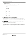
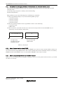
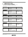
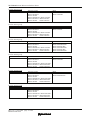
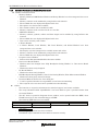
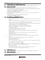
M3T-PD32R V.5.01 Release 00 Release Notes
Be sure to read this note.
M3T-PD32R V.5.01 Release 00
Release Notes
1st Edition
Renesas Solutions Corporation
October 1, 2006
Abstract
Welcome to M3T-PD32R V.5.01 Release 00 (hereafter referred to as PD32R).
This material explains the contents of the software, installation procedure, and supplements to the manual and help.
When using this software, take a look at the release note as well as the user’s manual.
Also, this document contains a License Agreement in the last. Read it before using. By using the software, you are
accepting and agreeing to such terms.
* You can get the latest version of this document from our homepage: (http://www.renesas.com/en/tools)
Contents
Components of the Product................................................................................................................................ 3
Operating Environment ..................................................................................................................................... 4
Installation........................................................................................................................................................... 5
3.1.
INSTALLING OF PD32R ................................................................................................................................ 5
3.2.
USER REGISTRATION .................................................................................................................................... 5
3.3.
INSTALLING OF ACROBAT READER .............................................................................................................. 5
3.4.
INSTALLING OF HTML HELP UPDATE COMPONENT .................................................................................. 5
4. Technical Support ............................................................................................................................................... 6
4.1.
TECHNICAL SUPPORT BY E-MAIL.................................................................................................................. 6
4.2.
TECHNICAL SUPPORT BY HOMEPAGE........................................................................................................... 6
5. Notes..................................................................................................................................................................... 7
5.1.
ANALYSIS OF REAL TIME TRACE RESULTS .................................................................................................... 7
5.2.
ZONE TIME MEASUREMENT ERROR .............................................................................................................. 7
5.3.
ZONE TIME MEASUREMENT EVENT ............................................................................................................ 10
5.4.
EVENT SETUP .............................................................................................................................................. 10
5.5.
PRECAUTIONS ON DOWNLOAD (1)............................................................................................................... 11
5.6.
PRECAUTIONS ON DEBUGGING .................................................................................................................. 12
5.7.
PRECAUTIONS WHEN USING TW32R (V.1.00 RELEASE 1 TO V.3.00 RELEASE 1) ................................... 13
5.8.
CHANGING MEMORY CONTENTS OF AN EXTERNAL FLASH ROM AREA ..................................................... 14
5.9.
ABOUT THE SCOPE ...................................................................................................................................... 14
5.10.
ABOUT WATCHING THE LOCAL C VARIABLES ............................................................................................. 14
5.11.
PRECAUTIONS ON DEBUGGING FUNCTIONS IN THE EXTERNAL AND EXTENDED EXTERNAL AREAS ......... 15
5.12.
ABOUT CUSTOM FUNCTION USING CB32R................................................................................................ 15
5.13.
ABOUT USING CAST OPERATORS FOR THE MEMBER VARIABLE ................................................................. 15
1.
2.
3.
Rev.1.00 10.01.2006 page 1 of 34
REJ10J1495-0100
M3T-PD32R V.5.01 Release 00 Release Notes
5.14.
ON THE BREAK FUNCTION USING THE PRE-EXECUTION PC BREAK .......................................................... 16
5.15.
ABOUT USING THE LPT PARALLEL INTERFACE ON THE HOST PC RUNNING WINDOWS XP.................... 17
6. Supplements of User’s Manual........................................................................................................................ 18
6.1.
MCU FILE LIST PROVIDED WITH THE PD32R PRODUCT ........................................................................... 18
6.2.
LIST OF FLASH DEVICE DEFINITION FILES (FDD FILES) PROVIDED WITH THE PD32R PACKAGE ........... 21
6.3.
SECURITY CODE CHECK FUNCTION ............................................................................................................ 23
6.4.
SETTING A BREAKPOINT IN THE PROGRAM/SOURCE WINDOW ................................................................. 23
6.5.
DISPLAY VALUE OF BREAKPOINT DISPLAY/SETTING AREA IN THE PROGRAM/SOURCE WINDOW ............ 23
7. Version Report................................................................................................................................................... 24
7.1.
PD32R V.5.01 RELEASE 00 ....................................................................................................................... 24
7.2.
PD32R V.5.00 RELEASE 00 ....................................................................................................................... 24
7.3.
PD32R V.4.10 RELEASE 1.......................................................................................................................... 25
7.4.
PD32R V.4.00 RELEASE 1.......................................................................................................................... 25
7.5.
PD32R V.3.00 RELEASE 1, PD32R V.3.00 RELEASE 1A ......................................................................... 27
7.6.
PD32R V.2.10 RELEASE 1.......................................................................................................................... 27
7.7.
PD32R V.2.00 RELEASE 2.......................................................................................................................... 28
7.8.
PD32R V.2.00 RELEASE 1.......................................................................................................................... 29
8. License Agreement ........................................................................................................................................... 31
Active X, Microsoft, MS-DOS, Visual Basic, Visual C++, Windows and Windows NT are either registered trademarks or trademarks of
Microsoft Corporation in the United States and other countries.
IBM and AT are registered trademarks of International Business Machines Corporation.
Intel and Pentium are registered trademarks of Intel Corporation.
Adobe and Acrobat are registered trademarks of Adobe Systems Incorporated.
All other brand and product names are trademarks, registered trademarks or service marks of their respective holders.
Rev.1.00 10.01.2006 page 2 of 34
REJ10J1495-0100
M3T-PD32R V.5.01 Release 00 Release Notes
1.
Components of the Product
PD32R V.5.01 Release 00 comprises the following:
!
Contents of the CD-ROM
1. PD32R installer files
The following files are installed after running the PD32R installer.
(1) Programs and files
" PD32R.EXE
" PD_LITE.EXE V. 8.50.01
" xxxxxx.dll
P32REDLL.DLL
V. 1.40.01
P32RRTOSWIN.DLL
V. 1.40.01
COMMUNI.DLL
V. 2.01.05
P32REMUWIN.DLL
V. 1.40.01
P32REGUI.DLL
V. 1.40.01
P32RRRAMWIN.DLL
V. 1.40.01
P32RCBENGINE.DLL
V. 1.40.01
MFC42.DLL
P32REVENTSETTING.DLL
V. 1.40.01
ATL.DLL
P32RRESOURCE.DLL
V. 1.40.01
MSVCRT.DLL
P32RGUIIOWIN.DLL
V. 1.40.01
MSVCP60.DLL
" M32RSDI0.S (Firmware file) V 2.01.36
" PDHELP.CHM
" PD32RDLL.DEF
" PD32R.FEF
" R.RDF, RF.RDF, RV.RDF, RX.RDF
" DEFAULT.SCK
" LOAD.SCR (The sample download script file for M32121)
" SETIP.EXE (The configuration program for the LAN interface)
" LPTFIX.EXE (The registry setup utilities for the LPT driver)
* For details, please refer to “5.15 About using the LPT parallel interface on the host PC
running Windows XP”.
" PD_LITE.TLB
The following files are stored in the ‘drivers’ directory under the directory that has PD32R installed
(eg: c:¥renesas¥pd32r¥drivers).
(a) The device drivers for the LPT interface.
(b) The device drivers for the USB interface.
File names
(a)
MLptDrv2.sys
(b)
MUsbDrv.sys
MUsbDrv.inf
Windows Me/98/95
Copied*
Windows XP/2000/NT
Installed**
Copied *
** The installer installs the files to the system.
* The installer copies the files under the target directory. And you need to install them when you use the USB interface.
- The installer does not copy the files.
Rev.1.00 10.01.2006 page 3 of 34
REJ10J1495-0100
M3T-PD32R V.5.01 Release 00 Release Notes
2. HTML Help Update Component
You may need HTML Help Update Component (provided by Microsoft Co. Ltd.) to browse HTML
Help Files (.CHM). If you can’t open the help file for PD32R, install and update this component in
your system (NOTE: You need to restart your system after installing).
!
Release Note for PD32R V.5.01 Release 00 (“Software User License Agreement” included).
"
"
"
2.
If any of the above is missing, contact either Renesas Technology Corporation's office or
its distributor from which you purchased the product.
Please read a License Agreement before using. By using the software, you are accepting
and agreeing to such terms.
The S/W Tool User Registration Sheet is used for maintenance service for you.
Operating Environment
PD32R runs on the operating environments given below.
Table 1: The Host Machine Requirements
Host Machine
Operating System
CPU
Memory
Rev.1.00 10.01.2006 page 4 of 34
REJ10J1495-0100
IBM PC/AT and its compatibles
Windows Me
Windows 98
Windows XP
Windows 2000
Windows NT 4.0
Pentium 3 500MHz or higher CPU is recommended.
192MB or more system memory is recommended.
M3T-PD32R V.5.01 Release 00 Release Notes
3.
Installation
[Notes for Windows XP/2000/NT 4.0]
When using Windows XP/2000/NT4.0 as an operating system, make sure that the installer is executed by
an authorized user as an Administrator. No one but the user with Administrator rights can install the
PD32R.
3.1.
Installing of PD32R
Register the PD32R to the Windows Me/98/95/XP/2000/NT4.0 by installing it to the hard disk using
the installer.
1.
Start of the installer
Use the Windows Explorer to view the CD-ROM. Navigate to the “setup.exe” file in the
¥PD32R¥W95E folder, and open the file to start the PD32R installer.
2.
Entering user information
In “Customer Information” dialog box, enter customer information (License User, Belong To, Your
Addresses, and PC types). Entered information becomes a format of a customer support by mail.
3.
Selection of component
In the "Select Components" dialog box, select the component to be installed. In the dialog box,
installation folder can be changed.
4.
End of the installer
The installation of PD32R is completed, when the “Setup is complete” dialog box appears.
3.2.
User Registration
The text file for the user registration is created to the start menu. Enter the necessary information to the
text file and send it to our registration desk ([email protected]). To open the text file for the user
registration, select the following menu:
Windows Menu [Start]->[Program]->[Renesas]->[PD32R V.5.01 Release 00]->[User Registration Sheet]
3.3.
Installing of Acrobat Reader
The manual of PD32R is provided as an electronic file. Acrobat Reader is necessary to browse the
electronic file. Acrobat Reader is stored in the Acrobat folder of the PD32R product disk. Install
Acrobat Reader if necessary. The latest version of Acrobat Reader can be downloaded from the home
page of the Adobe Systems.
URL for Adobe Systems: http://www.adobe.com/
3.4.
Installing of HTML Help Update Component
The Help for PD32R is provided as HTML Help file. Internet Explorer 4.0 or later is necessary to browse
HTML Help files.
If you can’t browse HTML Help files, you need install Internet Explorer 4.0 or later, HTML Help Update
Component, or both of them.
HTML Help Update Component (HHUPD.EXE) is stored in the “Utility” folder, which is created within
the folder that PD32R is installed (eg:c:¥renesas¥pd32r¥Utility¥Hhupd.exe). Install it if necessary. The
latest version of this component can be downloaded from the home page of Microsoft Co. Ltd.
URL for MSDN: http://msdn.microsoft.com/
Rev.1.00 10.01.2006 page 5 of 34
REJ10J1495-0100
M3T-PD32R V.5.01 Release 00 Release Notes
4.
Technical Support
4.1.
Technical support by E-mail
The text file for the technical support is created based on the information provided at installation. Write
your inquiry in it and send it to our technical support ([email protected]). To open the text file for
technical support, select the following menu:
Windows Menu [Start]->[Program]->[Renesas]->[PD32R V.5.01 Release 00]->[Technical Support Sheet]
[Notes on technical support]
We designate the types of host machines (IBM PC/AT and compatibles, for example) as an operation
environment for using our software tools. This does not guarantee operation of the host machines of any
kind or in any environment (such as device drivers, peripheral units, etc.), but merely for indicating an
operation environment we assume (to be put to our support). If a trouble should occur in using the
software tools in the operation environment we designate, we offer a technical support to solve the trouble
(defective correction and information for avoiding the trouble, and so forth).
If a trouble that occurred in your environment cannot be reproduced in our operation environment, we
may ask your cooperation (we may borrow your equipment with your approval). We would like your prior
approval.
4.2.
Technical support by Homepage
Our homepage in the following URL provides datasheets, toolnews, FAQ and the other various
information of our products.
Home Page: http://www.renesas.com/en/tools
Another access is:
Windows Menu [Start]->[Program]->[Renesas]
-> [(Link Page for) RENESAS Tools HomePage]
Rev.1.00 10.01.2006 page 6 of 34
REJ10J1495-0100
M3T-PD32R V.5.01 Release 00 Release Notes
5.
Notes
5.1.
Analysis of real time trace results
When the trace type is Branch, observe the following restriction on the result of real time trace,
depending on the setup condition or the occurred breakpoint setting.
"
When tracing up to the time point when the breakpoint occurs
When the real time trace result is displayed in the bus mode, the trace data at occurrence of the
breakpoint is listed as below. The trace data at Address: FFFF9000 indicates that a break
function has occurred. It does not indicate an occurrence of branch caused by the user program.
Trace data indicating break occurrence
The trace data at Address: FFFF9000 indicates that a break function
has occurred.
For the bus mode display, Address, ST and other fields, see the PD32R Help.
5.2.
Zone time measurement error
The zone time measurement function is implemented based on the trace data output from the MCU.
To output a unit of trace data information, the MCU operation clock frequency count shown below is
required. Thus, the zone time measurement result generates a measurement error from the actual
MCU execution time.
A unit of trace data refers to the following information:
(a) Single branch information arising during program execution
(b) Single data access information
According to the trace mode setting, the trace data output from the MCU are described below:
Trace Mode Setting
Trace Data Output from MCU
Branch
(a) Only branch information
Data
(b) Only data access information
Mix(Branch Priority)
(a)Branch information and (b) Data access information
Mix(Data Priority)
(b)Branch information and (b) Data access information
Rev.1.00 10.01.2006 page 7 of 34
REJ10J1495-0100
M3T-PD32R V.5.01 Release 00 Release Notes
"
Clock count required to output a unit of information
Emulator model, Patterns of connection
MCU
group
MCU operation
frequency
A unit of
information
outputted (a) Branch
information
(b) Data access
information
32102
-
M32Rx/D
-
32121
-
3217x
-
3218x
MCU clock
<= 66MHz
MCU clock
> 66MHz
MCU clock
<= 66MHz
66MHz <
MCU clock
<= 108MHz
108MHz <
MCU clock
<= 132MHz
MCU clock
> 132MHz
MCU clock
<= 66MHz
66MHz <
MCU clock
<= 108MHz
108MHz <
MCU clock
<= 132MHz
MCU clock
> 132MHz
(a)
(b)
(a)
(b)
(a)
(b)
(a)
(b)
(a)
(b)
(a)
(b)
(a)
(b)
(a)
32104
3219x
Rev.1.00 10.01.2006 page 8 of 34
REJ10J1495-0100
(b)
M32100T-SDI-E
or
M32170T-SDI
Number of
trace output
clocks
M32100T2-SDI-E
When
M32xxxT2-PTC
is not used
Number of
trace output
clocks
12
18
12
18
6
9
6
9
6
9
12
18
6
9
6
9
12
6
18
9
(a)
12
(b)
18
(a)
(b)
(a)
(b)
(a)
(b)
When
M32xxxT2-PTC
is used
Number of
trace output
clocks
24
36
12
18
6 (max)
9 (max)
12 (max)
6 (max)
18 (max)
9 (max)
(a)
12 (max)
(b)
18 (max)
(a)
(b)
24 (max)
36 (max)
12 (max)
18 (max)
M3T-PD32R V.5.01 Release 00 Release Notes
The zone time measurement error shown below is generated when Branch, Data or Trigger is
specified for the event setup function -- one of the zone time measurement functions. If Chip Event is
specified for the event setup function, no measurement error occurs.
"
Time measurement error (clock count required to output a unit of information x 2)
Emulator model, Patterns of connection
MCU
group
MCU operation
frequency
A unit of
information
outputted (a) Branch
information
(b) Data access
information
32102
-
M32Rx/D
-
32121
-
3217x
-
3218x
MCU clock
<= 66MHz
MCU clock
> 66MHz
MCU clock
<= 66MHz
66MHz <
MCU clock
<= 108MHz
108MHz <
MCU clock
<= 132MHz
MCU clock
> 132MHz
MCU clock
<= 66MHz
66MHz <
MCU clock
<= 108MHz
108MHz <
MCU clock
<= 132MHz
MCU clock
> 132MHz
(a)
(b)
(a)
(b)
(a)
(b)
(a)
(b)
(a)
(b)
(a)
(b)
(a)
(b)
(a)
32104
3219x
Rev.1.00 10.01.2006 page 9 of 34
REJ10J1495-0100
(b)
M32100T-SDI-E
or
M32170T-SDI
Number of time
measurement
error clocks
M32100T2-SDI-E
When
M32xxxT2-PTC
is not used
Number of time
measurement
error clocks
24
36
24
36
12
18
12
18
12
18
24
36
12
18
12
18
24
12
36
18
(a)
24
(b)
36
(a)
(b)
(a)
(b)
(a)
(b)
When
M32xxxT2-PTC
is used
Number of time
measurement
error clocks
48
72
24
36
12 (max)
18 (max)
24 (max)
12 (max)
36 (max)
18 (max)
(a)
24 (max)
(b)
36 (max)
(a)
(b)
48 (max)
72 (max)
24 (max)
36 (max)
M3T-PD32R V.5.01 Release 00 Release Notes
5.3.
Zone time measurement event
Setup of zone time measurement events has the following restrictions:
" When the same event is set for the start and end events, 1/2 of the event occurrence count will
be a measurement result.
" Set the start event and end event at interval of more than 200 ns in-between.
5.4.
Event setup
When setting an event in the state transition chart in the H/W Break Point Setting Window or Trace
Point Setting Window, observe the following restriction:
" If you specify a chip event and another event under other condition within the event assignment
button, the relation of occurrence time may be inverted, which will cause the system to fail to
correctly recognize the event to be specified in the state transition chart. To mix designation of
these events, occurrence of each event requires interval longer than the time measurement error
given in "5.2 Zone time measurement error".
Rev.1.00 10.01.2006 page 10 of 34
REJ10J1495-0100
M3T-PD32R V.5.01 Release 00 Release Notes
5.5.
Precautions on download (1)
When one of the following applies, the target microcomputer is reset, and the registers which sets
the memory wait count and clock frequency are initialized.
(1) Immediately after the PD32R gets started
(2) When pressing the RESET button on the PD32R (or when executing the Reset instruction)
(3) When downloading is completed (when the reset operation is enabled after downloading)
You can select the reset operation after downloading by using the "Download Behavior tab" in
the Init dialog box. For details, see the "Setup" section in the PD32R Help.
If you try to download the target program in such a state, the download speed may drastically
become slow. It is highly recommended that you should download the target program after setting
the memory wait count and clock frequency.
The following shows an example to download the program to the flash memory built in the target
microcomputer M32121.
When using a target microcomputer of other model, set the parameters referring to the given
example.
(Example: When using M32121)
Set the parameters to the register using the PD32R memory rewrite function.
Register
Address
Access size
Setting value
Setting data
Built-in ROM wait
H'FFFFC023
Byte
H'00
Built-in ROM wait
control register
count 0
Clock mode register
H'00F74000
Word
BCLKSEL=B'0000
System clock f (XIN)
The PD32R script instruction executes the following:
MB FFFC023, 0
MW 00F74000, 0
A script file LOAD.SCR in which the above data is described is attached.
Immediately after starting PD32R, it is automatically executed by specifying "Init File" on "Resume
tab" in "Init" dialog.
Download speed to the built-in flash memory is influenced by the setting data in the register above
(built-in ROM wait control register/clock mode register).
To download a target program to an external device, be sure to set the parameters of the built-in
chip select controller before starting downloading.
And, if you use microcomputer with a data caching function, you have to disable the function before
downloading a program.
Rev.1.00 10.01.2006 page 11 of 34
REJ10J1495-0100
M3T-PD32R V.5.01 Release 00 Release Notes
5.6.
5.6.1.
5.6.2.
5.6.3.
Precautions on Debugging
When using CC32R
" If the target program contains multiple object files with the same file name, debug
information on those objects cannot be handled correctly.
" Variables that are named “bool” can be referred neither with C Watch Window nor with print
command in Script Window.
When using D-CC
" If the target program has typedef declarations internally used, pay attention to the following:
(1) When displaying type definition names, respective tag names are displayed.
(2) When using type definition names to write C language expressions, be sure to use
respective tag names.
Common precautions
" In the first line of a function, the stack frame for the function is not fully formed. When
referencing function parameters or auto variables, execute as many lines in the function as
can be executed.
" If a variable is declared with the same name as the type definition name declared by typedef,
you cannot reference that variable.
Rev.1.00 10.01.2006 page 12 of 34
REJ10J1495-0100
M3T-PD32R V.5.01 Release 00 Release Notes
5.7.
Precautions when using TW32R (V.1.00 Release 1 to V.3.00 Release 1)
When you are using TW32R version from V.1.00 Release 1 to V.3.00 Release 1, the program header
information of the load module created by the linker may not be correctly generated. This may cause
a problem that a part of the section cannot be correctly downloaded by the emulator debugger.
[Condition which triggers this problem]
It has been proved that the problem occurs when a linker script is described where the
relationship between the section execution address (VMA) and the load address (LMA) meets the
two conditions given below. In the following example, section .secB is not downloaded correctly.
(1) Any three sections are allocated to the continuous load addresses (LMA) (Figure A).
(2) Only the execution address (VMA) of the section allocated in the middle (.secB) is allocated to
the low address (Figure B).
LMA
VMA
Low address
.secB
.secA
.secB
.secC
.secA
Figure A
Figure B
.secC
High address
[Corrective action]
Try one of the following methods:
(1) Changing the section allocation sequence
When allocating the load address (LMA) of each section, change the linker script description so
that a section whose execution address (VMA) is allocated to low address (.secB) will not be
placed between the sections whose execution address is the same as the load address
(.secA, .secC).
For example, change the section allocation sequence as shown in Figure C and Figure D.
LMA
VMA
Low address
.secB
.secA
.secC
.secB
.secA
.secC
Figure C
Figure D
High address
(2) Creating a program header using the PHDRS instruction
As shown in the following example, change the linker script.
Then, the system will create the program header for each section.
[1] In each section definition, define the name to be referenced in the PHDRS instruction. Be
sure to select the different name for each section. The defined name is used to be identified in
the PHDRS instruction. You can specify any name. (It could be the same as the symbol name,
Rev.1.00 10.01.2006 page 13 of 34
REJ10J1495-0100
M3T-PD32R V.5.01 Release 00 Release Notes
file name or section name.) However, you cannot specify an instruction name (NETRY,
STARTUP) for the name.
[2] Use the name defined in [1] to define the program header using the PHDRS instruction so
that all the sections will be used as individual segments.
---------------------------------------------------------/* [2] */
PHDRS
{
secA PT_LOAD;
secB PT_LOAD;
secC PT_LOAD;
}
.secA Execution address : Load address
{
...
} :secA
/* [1] */
.secB Execution address : Load address
{
...
} :secB
/* [1] */
.secC Execution address : Load address
{
...
} :secC
/* [1] */
----------------------------------------------------------
5.8.
Changing memory contents of an external flash ROM area
Memory contents of an external flash ROM area can only be changed during download processing.
The memory contents of this area cannot be changed by operating directly on memory. Here, the
external flash ROM area refers to one that was registered from the "Init" dialog box using its Target
Dependence Memory setup page.
5.9.
About the scope
The scope setting function is available only when the compiler CC32R is used. When D-CC or
TW32R is used, the scope setting function is unavailable.
5.10. About watching the local C variables
For the sake of optimization, the C compiler may place different variables at the same address. In
this case, values of the C variable may not be displayed correctly on the c watch window or other
function.
Rev.1.00 10.01.2006 page 14 of 34
REJ10J1495-0100
M3T-PD32R V.5.01 Release 00 Release Notes
5.11. Precautions on debugging functions in the external and extended external areas
The following debugging functions may not properly be performed in the external and extended
external areas:
(a) Storing target program to memory after downloading
(b) Rewriting memory
This problem occurs if the following three conditions are satisfied:
(1) The target MCU belongs to any of the following MCU groups:
* the 3212x groups
* the 3217x groups
* the 3218x groups
* the 3219x group
(2) The chip operation mode of the target MCU is either of the following:
* processor mode
* MPU mode
(3) The external or extended external area concerned overlaps with the internal ROM area, as
denoted by A in the memory map below.
Internal ROM Area
In single-chip,
extended external,
and MCU modes
A
In processor and
MPU modes
Memory map figure
5.12. About Custom function using CB32R
PD32R V.4.00 and later versions does not include CB32R. If you want to create custom windows, please use
the custom function using COM interface. The custom windows and custom commands, which are created by
CB32R attached with PD32R V.3.00, are executable in PD32R V.4.00 or newer version.
5.13. About using cast operators for the member variable
When you use cast operators for the member variable to refer to it as the pointer of the structure, you would
not refer to it correctly.
Rev.1.00 10.01.2006 page 15 of 34
REJ10J1495-0100
M3T-PD32R V.5.01 Release 00 Release Notes
5.14. On the break function using the pre-execution PC break
[Description]
When the pre-execution PC break is used as an event of a breakpoint, the break function may not be
performed properly.
[Conditions]
This problem occurs if the following four conditions are satisfied:
(1) The target MCU belongs to any of the following groups:
32170, 32171, 32172, 32173, 32174, and 32176
(2) The pre-execution PC break is used as an event of a breakpoint.
(3) The pre-execution PC break is used as an event of a chip event.
(4) The breakpoint and the chip event in (2) and (3) above are set at the same address.
[Example]
If the target program is started with a breakpoint being set in the procedure shown below, no
program break occurs when the instruction at the specified address (1000H, for example) is
executed:
(1) Open the Program window and double-click the mouse's left button in the area for setting a
breakpoint at address 1000H. A breakpoint is set at that address. In Single Chip and External
Expansion Modes of the M3217x group, address 1000H is within the internal ROM area, so the
pre-execution PC break is used as a breakpoint and "b"s are displayed in the breakpoint display
area.
(2) Follow these steps in the Trace-point setting window:
1. Click the CE0 button in the Set Chip Event area. The CE0-Set Chip Event dialog box appears.
2. Perform the following in the CE0-Set Chip Event dialog box:
2.1 Check the Enable check box.
2.2 Select "Preexe-PC 0" in the Event Type combo box.
2.3 Type H'1000 in the Address text box.
2.4 Click the OK button.
3. Click the Set button.
[Workaround]
Don't set a breakpoint and a chip event that use the pre-execution PC break as their events at the
same address.
Rev.1.00 10.01.2006 page 16 of 34
REJ10J1495-0100
M3T-PD32R V.5.01 Release 00 Release Notes
5.15. About using the LPT parallel interface on the host PC running Windows XP
When you debug programs using the LPT parallel interface on the host PC running Windows XP, the
following symptoms may appear:
1. The debugger becomes frozen.
2. The debugger's operation gets extraordinarily slower.
3. Communication errors arise and the emulator debugger stops operating.
4. Various types of errors other than communication errors also take place successively. In this case,
the emulator debugger continues operating however.
The cause of this problem is that if the debugger is invoked while the standard driver Parport.sys of
Windows XP is communicating with the LPT port, the debugger is unable to communicate with the
emulator.
Then, this problem can be circumvented in either of the following methods; however, you need to take no
measures if you have not experienced it in your PC under the above-mentioned conditions:
(a) Execute the problem-fixing LptFix.exe file as follows (NOTICE 1):
(1) The LptFix.exe file is stored in a location below the directory where the PD32R is installed (e.g.,
c:¥renesas¥PD32R¥utility).
(2) Invoke the command prompt of Windows XP by selecting the Start -> Program -> Accessory ->
Command Prompt command and move to the folder where the LptFix.exe file resides.
(3) Enter the following command on the command line:
>LptFix
Here > denotes a command prompt.
(4) Restart the PC.
NOTICES:
1. Executing the LptFix.exe disables the Parport.sys driver. Then, if any device other than the emulator
is connected to the LPT port after LptFix.exe is executed, the device may not operate properly. In
such a case you are encouraged to adopt method (b) shown later.
2. If LptFix.exe is executed, be sure to make it ineffective to enable the Parport.sys driver as explained
below, every time after ending debugging operations and disconnecting the emulator.
To make LptFix.exe ineffective to enable Parport.sys, go through the following steps:
(1) Invoke the command prompt and move to the folder where the LptFix.exe file resides.
(2) Enter the following command on the command line:
>LptFix /U
(3) Restart the PC.
(b) If you launch the emulator for the first time after starting the PC, invoke the debugger one or more
minutes after the emulator starts operating. Otherwise, you can invoke the debugger immediately after
the emulator has started.
Rev.1.00 10.01.2006 page 17 of 34
REJ10J1495-0100
M3T-PD32R V.5.01 Release 00 Release Notes
6.
Supplements of User’s Manual
6.1.
MCU file list provided with the PD32R product
MCU files provided with PD32R V.5.01 Release 00 are listed below.
Use the MCU file corresponding to your emulator system.
For the 32102 group
MCU file name
32102.mcu
Emulator model
M32100T2-SDI-E
M32100T-SDI-E
M32170T-SDI
MCU
M32102S6FP
Emulator model
M32100T2-SDI-E
M32100T-SDI-E
M32170T-SDI
M32100T2-SDI-E + M32104T2-PTC
M32100T-SDI-E + M32104T2-PTC
M32170T-SDI + M32104T2-PTC
MCU
M32104S6FP
M32104S6WG
Emulator model
M32100T2-SDI-E
M32100T-SDI-E
M32170T-SDI
MCU
M32121FCWG
Emulator model
M32100T2-SDI-E
M32100T-SDI-E
M32170T-SDI
M32100T2-SDI-E + M32170T-PTC
M32100T-SDI-E + M32170T-PTC
M32170T-SDI + M32170T-PTC
MCU
M32170F3VFP
M32170F4VFP
M32170F6VFP
Emulator model
M32100T2-SDI-E
M32100T-SDI-E
M32170T-SDI
M32100T2-SDI-E + M32171T-PTC
M32100T-SDI-E + M32171T-PTC
M32170T-SDI + M32171T-PTC
MCU
M32171F2VFP
M32171F3VFP
M32171F4VFP
Emulator model
M32100T2-SDI-E
M32100T-SDI-E
M32170T-SDI
M32100T2-SDI-E + M32173T-PTC
M32100T-SDI-E + M32173T-PTC
M32170T-SDI + M32173T-PTC
MCU
M32172F2VFP
For the 32104 group
MCU file name
32104.mcu
For the 32121 group
MCU file name
32121.mcu
For the 32170 group
MCU file name
32170.mcu
For the 32171 group
MCU file name
32171.mcu
For the 32172 group
MCU file name
32172.mcu
Rev.1.00 10.01.2006 page 18 of 34
REJ10J1495-0100
M3T-PD32R V.5.01 Release 00 Release Notes
For the 32173 group
MCU file name
32173.mcu
Emulator model
M32100T2-SDI-E
M32100T-SDI-E
M32170T-SDI
M32100T2-SDI-E + M32173T-PTC
M32100T-SDI-E + M32173T-PTC
M32170T-SDI + M32173T-PTC
MCU
M32173F2VFP
M32173F2VWG
Emulator model
M32100T2-SDI-E
M32100T-SDI-E
M32170T-SDI
M32100T2-SDI-E + M32170T-PTC
M32100T-SDI-E + M32170T-PTC
M32170T-SDI + M32170T-PTC
MCU
M32174F3VFP
M32174F4VFP
Emulator model
M32100T2-SDI-E
M32100T-SDI-E
M32170T-SDI
M32100T2-SDI-E + M32170T-PTC
M32100T-SDI-E + M32170T-PTC
M32170T-SDI + M32170T-PTC
MCU
M32176F2VFP/TFP
M32176F2VWG/TWG
M32176F3VFP/TFP
M32176F3VWG/TWG
M32176F4VFP/TFP
M32176F4VWG/TWG
Emulator model
M32100T2-SDI-E
M32100T-SDI-E
M32170T-SDI
M32100T2-SDI-E + M32180T2-PTC
M32100T-SDI-E + M32180T2-PTC
M32170T-SDI + M32180T2-PTC
MCU
M32180F8TFP/VFP
M32180F8VWG
Emulator model
M32100T2-SDI-E
M32100T-SDI-E
M32170T-SDI
M32100T2-SDI-E + M32182T2-PTC
M32100T-SDI-E + M32182T2-PTC
M32170T-SDI + M32182T2-PTC
MCU
M32182F3TFP/VFP
M32182F8TFP/VFP
Emulator model
M32100T2-SDI-E
M32100T-SDI-E
M32170T-SDI
M32100T2-SDI-E + M32186T2-PTC
M32100T-SDI-E + M32186T2-PTC
M32170T-SDI + M32186T2-PTC
MCU
M32185F4VFP
For the 32174 group
MCU file name
32174.mcu
For the 32176 group
MCU file name
32176.mcu
For the 32180 group
MCU file name
32180.mcu
For the 32182 group
MCU file name
32182.mcu
For the 32185 group
MCU file name
32185.mcu
Rev.1.00 10.01.2006 page 19 of 34
REJ10J1495-0100
M3T-PD32R V.5.01 Release 00 Release Notes
For the 32186 group
MCU file name
32186.mcu
Emulator model
M32100T2-SDI-E
M32100T-SDI-E
M32170T-SDI
M32100T2-SDI-E + M32186T2-PTC
M32100T-SDI-E + M32186T2-PTC
M32170T-SDI + M32186T2-PTC
MCU
M32186F8VFP
Emulator model
M32100T2-SDI-E
M32100T-SDI-E
M32170T-SDI
M32100T2-SDI-E + M32192T2-PTC
M32100T-SDI-E + M32192T2-PTC
M32170T-SDI + M32192T2-PTC
MCU
M32192F8TFP/UFP/VFP
M32192F8VWG/UWG/TWG
Emulator model
M32100T2-SDI-E
M32100T-SDI-E
M32170T-SDI
M32100T2-SDI-E + M32192T2-PTC
M32100T-SDI-E + M32192T2-PTC
M32170T-SDI + M32192T2-PTC
MCU
M32195F4VFP/UFP/TFP
Emulator model
M32100T2-SDI-E
M32100T-SDI-E
M32170T-SDI
M32100T2-SDI-E + M32192T2-PTC
M32100T-SDI-E + M32192T2-PTC
M32170T-SDI + M32192T2-PTC
MCU
M32196F8VFP/UFP/TFP
Emulator model
M32310T-SDI-E
MCU
M32310D5XX
For the 32192 group
MCU file name
32192.mcu
For the 32195 group
MCU file name
32195.mcu
For the 32196 group
MCU file name
32196.mcu
For the 32310 group
MCU file name
32310.mcu
32310_MPU.mcu
(Note) Usually, use 32310.mcu.
For the 32910 group
MCU file name
32910.mcu
Emulator model
M32120T-SDI for M32920
MCU
M32920
(Note)
When PD32R is installed, these MCU files are stored under "MCUfiles" folder, which is created
within the folder that contains PD32R.EXE.
Rev.1.00 10.01.2006 page 20 of 34
REJ10J1495-0100
M3T-PD32R V.5.01 Release 00 Release Notes
6.2.
List of flash device definition files (FDD files) provided with the PD32R package
Before the target program can be downloaded into an external flash area, a flash target definition file
(FTD file) must be registered from the "Init" dialog box using its Target Dependence Memory tab.
This FTD file can be created using the FDD files provided with the PD32R package. To create an FTD file,
select Flash ROM for Type: on the "Init" dialog box’s Target Dependence Memory tab and click the Create
button to open the "External Flash ROM Define" dialog box. Use this dialog box to create an FTD file. When
working on this dialog box, be sure to use the FDD file that suits the flash device used.
The table below lists the currently supported flash device type names and the flash device definition files
(FDD files) provided with PD32R V.5.01 Release 00.
(Notes)
1. To download the target program into an external flash area, check to be sure that it can be
read from and written into the flash memory. After that, download the target program into an
external flash area.
2. The operations of some flash memory are not verified due to patterns of connection.
FDD files for Atmel flash devices
FDD file name
AT49BV1614.FDD
Flash device type name (not
including the package shape)
AT49BV1614
Remarks
FDD files for Fujitsu flash devices
FDD file name
MBM29BL160D.FDD
MBM29BL161D.FDD
MBM29BL162D.FDD
MBM29DL16XBE.FDD
MBM29DL16XTE.FDD
MBM29DL32XBE.FDD
MBM29DL32XTE.FDD
MBM29DL640E.FDD
MBM29F400BC.FDD
MBM29F400TC.FDD
MBM29F800BA.FDD
MBM29F800TA.FDD
MBM29LV160BE.FDD
MBM29LV160TE.FDD
MBM29PL160BD.FDD
MBM29PL160TD.FDD
MBM29PL3200BE.FDD
Flash device type name (not
including the package shape)
MBM29BL160D
MBM29BL161D
MBM29BL162D
MBM29DL16XBx
MBM29DL16XTx
MBM29DL32XBx
MBM29DL32XTx
MBM29DL640x
MBM29F400Bx
MBM29F400Tx
MBM29F800Bx
MBM29F800Tx
MBM29LV160Bx
MBM29LV160Tx
MBM29PL160Bx
MBM29PL160Tx
MBM29PL3200Bx
MBM29PL32TE.FDD
MBM29PL32BE.FDD
MBM29PL65LM.FDD
MBM29LV800BA.FDD
MBM29LV800TA.FDD
MBM29LV320BE.FDD
MBM29LV320TE.FDD
MBM29LV640UE.FDD
MBM29PL32Tx
MBM29PL32Bx
MBM29PL65LM
MBM29LV800Bx
MBM29LV800Tx
MBM29LV320Bx
MBM29LV320Tx
MBM29LV640Ux
Rev.1.00 10.01.2006 page 21 of 34
REJ10J1495-0100
Remarks
x : 1, 2, 3, 4
x : 1, 2, 3, 4
x : 1, 2, 3, 4
x : 1, 2, 3, 4
------
available only when DW/W#
pin’s logic level is low
M3T-PD32R V.5.01 Release 00 Release Notes
FDD files for Intel flash devices
FDD file name
E28F016SV.FDD
E28F320J5.FDD
E28F640J5.FDD
Flash device type name (not
including the package shape)
E28F016SV
E28F320J5
E28F640J5
Remarks
FDD files for Renesas flash devices
FDD file name
M5M29FB160.FDD
M5M29FT160.FDD
M5M29GB320.FDD
M5M29GT320.FDD
M5M29KB331.FDD
M5M29KT331.FDD
M5M29KB331_WP.FDD
M5M29KT331_WP.FDD
M5M29KB641AVP.FDD
M5M29KT641AVP.FDD
Flash device type name (not
including the package shape)
M5M29FB160
M5M29FT160
M5M29GB320
M5M29GT320
M5M29KB331
M5M29KT331
M5M29KB331
M5M29KT331
M5M29KB64
M5M29KT641
Remarks
available only when WP#
pin’s logic level is high
available only when WP#
pin’s logic level is low
available only when WP#
pin’s logic level is high
FDD files for Toshiba flash devices
FDD file name
TC58FVB160.FDD
Flash device type name (not
including the package shape)
TC58FVB160
Remarks
FDD files for Macronix flash devices
FDD file name
MX29LV160B.FDD
MX29LV160T.FDD
MX29LV320B.FDD
MX29LV320T.FDD
MX29LV800T.FDD
MX29LV800B.FDD
MX26L6420.FDD
Flash device type name (not
including the package shape)
MX29LV160B
MX29LV160T
MX29LV320B
MX29LV320T
MX29LV800T
MX29LV800B
MX26L6420
Remarks
FDD files for SPANSION flash devices
FDD file name
S29GL128N.FDD
S29GL256N.FDD
S29PL032J.FDD
S29PL064J.FDD
Flash device type name (not
including the package shape)
S29GL128N
S29GL256N
S29PL032J
S29PL064J
Remarks
(Note)
When PD32R is installed, these FDD files are stored under "FddFiles" folder, which is created
within the folder that contains PD32R.EXE.
Rev.1.00 10.01.2006 page 22 of 34
REJ10J1495-0100
M3T-PD32R V.5.01 Release 00 Release Notes
6.3.
Security code check function
When starting PD32R in which a security code is stored, the following dialog appears. Enter the
security code here. If the entered security code does not match the stored one, PD32R will not get
started until the data in the built-in flash memory is deleted.
Enter the security code in the edit box.
Select the security code format by using a radio button in the Format group.
When checking the Save check box, the entered security code is saved.
When you try to start PD32R at next time, the system uses the saved security code to verify
conformance to the stored security code.
6.4.
Setting a breakpoint in the Program/Source Window
When you try to set a breakpoint in the Program/Source Window at an write-protected area, a
pre-execution PC breakpoint is set.
6.5.
Display value of breakpoint display/setting area in the Program/Source Window
In the breakpoint display/setting area in the Program/Source Window, "b" is displayed when a
pre-execution PC breakpoint has been set, and "p" is displayed when a post-execution PC breakpoint
has been set.
If a software breakpoint, hardware breakpoint (instruction branch), a pre-execution PC breakpoint
and a post-execution PC breakpoint are set at the same address, "ALL" is displayed in the
breakpoint display/setting area in the Program/Source Window.
Rev.1.00 10.01.2006 page 23 of 34
REJ10J1495-0100
M3T-PD32R V.5.01 Release 00 Release Notes
7.
Version Report
This section describes the changes in the specification.
7.1.
PD32R V.5.01 Release 00
In this version, the following changes have been made to the previous version PD32R V.5.00 Release 00.
7.1.1. Revisions of Restrictions
" A limitation has been corrected: If a mixed representation of source and disassembled code is saved on a text
file, a part of the disassembled code may not be saved on the file.
(for details, refer the RENESAS TOOL NEWS, June 16, 2006 (RSO-M3T-PD32RM-060616D))
A limitation has been corrected: When structure member variables, union member variables, or class member
"
variables are displayed in such a window as the C Watch window, which is capable of referencing variables, a
message may appear saying "not active", resulting in no variables being referenced.
7.1.2.
"
"
-
(for details, refer the RENESAS TOOL NEWS, January 16, 2006 (RSO-M3T-PD32RM-060116D))
Extended Functions and Modified Specifications
Window-related Functions
Debugging Information tab of Init Dialog Box
# Unsupported compiler Green Hills M32R has been unavailable on the Compiler's list box.
Others
The following MCU-files have been added.
32185.mcu
32186.mcu
32195.mcu
32196.mcu
7.2.
PD32R V.5.00 Release 00
In this version, the following changes have been made to the previous version PD32R V.4.10 Release 1.
7.2.1. Revisions of Restrictions
" A limitation has been corrected: In the C Watch window, expanding a global variable in a structure,
a union, or an array of structures or unions may cause the emulator debugger to terminate
unsuccessfully.
(for details, refer the RENESAS TOOL NEWS, September 1, 2004 (RSO-M3T-PD32RM-040901D))
" A limitation has been corrected: If structures, unions, classes, arrays, and pointers are expanded,
the emulator debugger may hang up.
(for details, refer the RENESAS TOOL NEWS, August 1, 2004 (RSO-M3T-PD32RM_1-040801D))
" A limitation has been corrected: Using the SetIp.exe file included with the product may not set an
IP address and others in the emulator.
(for details, refer the RENESAS TOOL NEWS, June 1, 2004 (RSO-M3T-PD308F-040601D))
7.2.2. Extended Functions and Modified Specifications
" Renesas C/C++ Compiler for M32R Family Support
PD32R newly supports ELF/DWARF2 format from M3T-CC32R, the Renesas C/C++ Compiler for
M32R Family, V.5.00 Release 00 and the later versions. It makes source level debugging of C++
programs available.
To debug a target program in ELF/DWARF2 format from M3T-CC32R, operate that as follows.
(1) Init Dialog Box
Select “CC32R(M32R)” or “CC32R(M32Rx) for “Compiler”, and ELF/DWARF2.0 for Object
Format in the Debugging Information Tag.
(2) Specifying file when loading
Select an object file with “elf” extension.
" Renesas uITRON-specification V.4.0 real-time OS Support
PD32R newly supports M3T-MR32R/4, the Renesas real-time OS for M32R Family, V.4.00 Release
00 and the later versions. It makes debugging of programs using M3T-MR32R/4 available.
Rev.1.00 10.01.2006 page 24 of 34
REJ10J1495-0100
M3T-PD32R V.5.01 Release 00 Release Notes
"
Others
- The following FDD-files have been added.
MBM29DL640E.FDD
MBM29PL65LM.FDD
M5M29KT331.FDD
M5M29KB641AVP.FDD
S29GL128N.FDD
-
MBM29PL3200BE.FDD
MBM29F800BA.FDD
M5M29KB331_WP.FDD
M5M29KT641AVP.FDD
S29PL032J.FDD
MBM29PL32TE.FDD
MBM29F800TA.FDD
M5M29KT331_WP.FDD
MX29LV800T.FDD
S29PL064J.FDD
MBM29PL32BE.FDD
M5M29KB331.FDD
M5M29KB641AVP.FDD
MX29LV800B.FDD
The following MCU-file has been added.
32192.mcu
7.3.
PD32R V.4.10 Release 1
In this version, the following changes have been made to the previous version PD32R V.4.00 Release 1.
7.3.1. Revisions of Restrictions
" A limitation has been corrected: A member of a struct or union may not correctly be referenced. If
you try referencing it, the debugger will unsuccessfully terminate in some cases.
(for details, refer the RENESAS TOOL NEWS, November 1, 2003
(RSO-M3T-PD32RSIM-031101D))
" A limitation has been corrected: If the Memory window remains minimized immediately after
launching the debugger, restoring or maximizing it causes the debugger to terminate
unsuccessfully.
(for details, refer the RENESAS TOOL NEWS, December 1, 2003 (RSO-M3T-PD32RM-031201D))
7.3.2. Extended Functions and Modified Specifications
" Window-related Functions
−
Trace Window
# A function has been added which displays the trace measurement results in mixed
format with two or more display modes.
# A function has been added which displays the trace measurement results distinguished
by using different colors.
−
MR Window
# A function has been added which allows the state of the following objects to be displayed
in the MR window.
Message buffers, Rendezvous ports, Mail-boxes with priority
# A function has been added which allows the state of the objects to be displayed in the MR
window during the target program running.
−
Script Window
# ADDPATH command is added. This command adds the search path.
7.4.
PD32R V.4.00 Release 1
In this version, the following changes have been made to the previous version PD32R V.3.10 Release 1 and
PD32R V.3.10 Release 1A.
7.4.1. Revisions of Restrictions
" A limitation has been corrected: When SYSROF-formatted files are downloaded, the program may
go into an infinite loop, causing the products concerned not to respond.
(for details, refer the MAEC TOOL NEWS, December 16, 2002
(MAECT-M3T-PD32RSIM_1-021216D))
" A limitation has been corrected: If the downloading of target programs described in ELF/DWARF
format is canceled in progress, the debugger may be terminated forcefully.
(for details, refer the MAEC TOOL NEWS, July 16, 2002 (MAECT-M3T-PD32RSIM-020716D))
Rev.1.00 10.01.2006 page 25 of 34
REJ10J1495-0100
M3T-PD32R V.5.01 Release 00 Release Notes
7.4.2. Extended Functions and Modified Specifications
" Window-related Functions
−
Memory Window
# Memory Window, RAM Monitor Window and Dump Window have been integrated into a new
Window.
# Memory contents can be modified by using In-Place edit function.
# The modified data are displayed hi-lighted with color.
# The splitter view has become available.
# The column numbers can be modified (1-256).
# Memory contents can be saved in the file as a text file.
−
ASM Watch Window
# Memory contents, symbols, radixes and data length can be modified by using In-Place edit
function.
# The modified data are displayed hi-lighted with color.
# Data can be sorted by each column.
−
C Watch Window
# C Watch Window, Local Window, File Local Window, and Global Window have been
integrated into a new window.
# The display style has changed to list variable names and values.
# Memory contents can be modified by using In-Place edit function.
# The modified data are displayed hi-lighted with color.
−
Program / Source Window
# Back scroll in Dis-Assemble Mode has become available.
−
Data Access Break Window
# Window name has changed form “Chip Breakpoint Setting Window” to “Data Access Break
Window”.
# Window has been newly designed.
−
PC Break Window
# Window has been newly designed.
−
H/W Breakpoint Setting Window, Trace Point Setting Window, Time Measurement Window
# Window has been partly altered in design.
−
Download Behavior Tab on the “Init” dialog box
# It can be specified whether the target MCU is reset before downloading.
# The script file to be executed can be specified before downloading.
" Others
−
The function, to output the information for technical support, has become available.
−
The script command called “OpenWindow” has been added to open a specified window from
the Script Window.
−
The file, which is opened in Program/ Source window, can be opened within the HEW, when
PD32R started up as the external debugger of HEW.
−
The following FDD-files have been added.
MBM29LV320BE.FDD
MBM29LV800TA.FDD
MX29LV320B.FDD
MBM29LV320TE.FDD
MX26L6420.FDD
MX29LV320T.FDD
MBM29LV640UE.FDD
MX29LV160B.FDD
−
The following MCU-file has been added.
−
−
C++ debugging functions have been available.
ResetMask script command has been made to function correctly.
32176.mcu
Rev.1.00 10.01.2006 page 26 of 34
REJ10J1495-0100
MBM29LV800BA.FDD
MX29LV160T.FDD
M3T-PD32R V.5.01 Release 00 Release Notes
7.5.
PD32R V.3.00 Release 1, PD32R V.3.00 Release 1A
In this version, the following changes have been made to the previous version PD32R V.2.10 Release 1.
7.5.1. Revisions of Restrictions
" A limitation has been corrected: If a Windows application is launched or any of the other
already-opened Windows applications is made active while you are downloading a target program (a
load module), the debugger may freeze suddenly.
(for details, refer the MAEC TOOL NEWS, December 16, 2001
(MAECT-M3T-PD32RSIM-011216D))
" A limitation has been corrected: The Source window may not be opened or not display materials
normally if opened.
(for details, refer the MAEC TOOL NEWS, December 16, 2001
(MAECT-M3T-PD32RSIM-011216D))
7.5.2. Extended Functions and Modified Specifications
"
Window-related Functions
−
The user interfaces for event setting of the H/W Break Point and Trace Point has been
reformed.
# The previous H/W Break Point Setting Dialog Box and the previous State Transition Break
Window has been unified to a new H/W Break Point Setting Window.
# The previous Trace Point Setting Dialog Box and the previous State Transition Trace Window
has been unified to a new Trace Point Setting Window.
# The drag-and-drop has become available to make usability better.
# The windows and dialog boxes of PD32R have been resized smaller.
−
Program/Source Windows
# It facilitates editing the source file on the window.
# The MIX mode display can be stored to text files.
# The way to specify the source file name in the Source Dialog Box has been improved.
−
Memory Window
# The display start position can be automatically changed as the stack pointer moves.
−
ASM Watch Window
# Watch points can be also displayed in signed decimal
# The Refresh Button has been added. You can update the display of the memory contents.
"
Others
−
This software has become compatible with the 32104 Group, 3218x Group.
−
The MCU files have been renewed.
−
The Drag-and-drop function
With the drag-and-drop operations, you can load files, set events, set the display start position,
add watch points, set or move data, and so on.
−
Auto Completion for the Address Setting.
When you enter some characters for the label string in the address setting combo-boxes, the
characters are completed to a label string that corresponds.
−
Buttons on the Toolbars
# The buttons on the toolbars has been resized smaller and changed to the icons.
# You can select styles (Flat style/Text labels/ etc.) of buttons.
7.6.
PD32R V.2.10 Release 1
In this version, the following changes have been made to the former version PD32R V.2.00 Release 2.
7.6.1. Revisions for Restrictions
" The following problem has been fixed:
Rev.1.00 10.01.2006 page 27 of 34
REJ10J1495-0100
M3T-PD32R V.5.01 Release 00 Release Notes
"
"
"
7.6.2.
"
"
(1) Time in real-time tracing may be displayed as 00"00'00:000.000.
Time information can be viewed in the following window and commands:
- the Trace window
- the TraceData command
- the TraceList command
(2) Measurement results in the Time Measurement Window may also be displayed as
00"00'00:000.000.
(for detail, refer the MAEC TOOL NEWS, April 1, 2001 (MAECT-PD32R-010401D))
The FDD-files (M5M29FB160.FDD, MBM29FT160.FDD) have been modified.
(for detail, refer the MAEC TOOL NEWS, April 1, 2001 (MAECT-PD32R-010401D))
The FDD-files (MBM29DL32XTE.FDD, MBM29DL32XBE.FDD) have been modified.
(for detail, refer the MAEC TOOL NEWS, April 16, 2001 (MAECT-PD32R-010416D))
The following problem has been fixed: When you watch the C variables in C watch window with the
following all conditions, PD32R will be terminated forcibly.
(1) the variable is local or file local variable.
(2) you cast it to the typedefed type.
(3) the variable is not in the current scope.
(for detail, refer the MAEC TOOL NEWS, August 1, 2001 (MAECT-PD32RSIM-010801D))
Extended Function
M32100T2-SDI-E has been available
The following FDD-files have been added.
AT49BV1614.FDD
MBM29DL16XBE.FDD
E28F320J5.FDD
"
MBM29BL160D.FDD
MBM29DL16XTE.FDD
E28F640J5.FDD
MBM29BL161D.FDD
MBM29LV160BE.FDD
TC58FVB160.FDD
MBM29BL162D.FDD
MBM29LV160TE.FDD
The following MCU-files have been added.
M32171F2VFP_MCU.mcu
M32171F2VFP_MPU.mcu
M32171F2PTC_MCU.mcu
M32171F2PTC_MPU.mcu
M32174F3VFP_MCU.mcu
M32174F3VFP_MPU.mcu
M32174F3PTC_MCU.mcu
M32174F3PTC_MPU.mcu
M32174F4VFP_MCU.mcu
M32174F4VFP_MPU.mcu
M32174F4PTC_MCU.mcu
M32174F4PTC_MPU.mcu
7.7.
PD32R V.2.00 Release 2
In this version, the following changes have been made to the former version PD32R V.1.00 Release 1.
7.7.1. Revisions of Restrictions
" A limitation has been corrected: When a program is downloaded to the internal or external flash
memory with LPT selected as the communication interface, download may not terminate correctly.
(for details, refer to the MAEC TOOL NEWS (MESCT-PD32R-010116D))
" The following problem has been fixed: When a software breakpoint is set at the built-in flash
memory area with the target board and the emulator (M32120T-SDI) connected through in-circuit
connection, the software breakpoint may not be cleared.
" The following problem has been fixed: COME command fails to be executed in ROM area.
" The following problem has been fixed: Values of the BPC register is not displayed in the execution
results of Register command.
" The following problem has been fixed: When a chip breakpoint is set with the target board in
operation, the chip breakpoint does not function correctly.
7.7.2. Modified Specification
" The method for accessing memory when acquiring object code from memory during disassemble
processing has been changed.
(Previous version) Fixed to bytewise access
(New version) Any access method--bytewise, halfwordwise, or wordwise--can be selected that is
supported for the target memory area.
Rev.1.00 10.01.2006 page 28 of 34
REJ10J1495-0100
M3T-PD32R V.5.01 Release 00 Release Notes
7.8.
PD32R V.2.00 Release 1
7.8.1. Revisions of Restrictions
" A limitation has been corrected: If any structure whose member names exceed 1,024 characters in
total is displayed on the C Watch, Global, File Local, or Local window, the debugger may be forcibly
terminated.
(for detail, refer the MESC TOOL NEWS, October 16, 2000 (MESCT-PD32RSIM-001016D))
7.8.2. Extended Function
"
Window-related Functions
−
GUI Input Window
GUI Input Window has been added. You can make a virtual key input panel on this window. This
window works as virtual input port.
−
GUI Output Window
GUI Output Window has been added. You can make a virtual output panel on this window.
−
Call Stack Window
Call Stack Window has been added. This window displays function call information of C language.
−
Dump Window, RAM Monitor Window and Memory Window
• You can specify display start address, when you open a Dump Window, RAM Monitor
Window or Memory Window.
• The display start address of the Dump Window, RAM Monitor Window or Memory Window is
displayed on the title bar.
−
ASM watch window
• It has been made possible to specify a data length when registering watch points by bit
specification.
−
C Watch Window and ASM Watch Window
• You can specify where C and ASM watch point file is saved.
• You can save C and ASM watch points by each project.
−
Script Window
• Command history can be saved. When you type up-arrow or down-arrow key on the input
field in focus, commands in the history can appear in order.
• RELOAD command has been added. This command reloads your last target program.
−
PD Window
• You can switch the display of the toolbar on or off.
−
PC Break Window
• A PC break window has been added, from which pre-execution PC or post-execution PC
breakpoints can be set and inspected.
−
Hardware breakpoint setup dialog box, trace point setup dialog box, state transition break
window, state transition trace window, and time measurement window
• It has been made possible to set a data information output address range during data trace.
" Others
−
Customizing User Interfaces
Shortcut key assignment and toolbar customizing functions have been added.
−
Shortcut menu
Right click on each window displays its own option menu as a shortcut.
−
Supplemental Download Function for Binary Data
After downloading an absolute module file, you can download supplemental binary data (MOT
files) with keeping symbol debugging information.
−
Saving window information and Resuming
Size, location and the other information of each window resume at opening each window. This
Rev.1.00 10.01.2006 page 29 of 34
REJ10J1495-0100
M3T-PD32R V.5.01 Release 00 Release Notes
resuming function has been made possible to work not only at starting PD32R but also while the
PD32R in operation.
−
Listing of All Labels in Address Setting Field
All labels are listed in each address setting fields. When you set a label for an address, you can
select it from the list.
−
Online Help
Online help has been changed to HTML Help.
−
Downloading into an external flash ROM area
It has been made possible to download the target program into an external flash ROM area.
Information on this external flash ROM must be registered from the Init dialog box using its
Target Dependence Memory setup page.
−
Changing trace point or breakpoint settings during target execution
It has been made possible to change trace point or breakpoint settings while executing the target.
−
Changing memory contents of an internal flash ROM area
It has been made possible to change memory contents of an internal flash ROM area by other
means as well as download processing.
−
C compiler CC32R V.3.00
The debugger now supports enhanced #pragma of the C compiler CC32R V.3.00.
7.8.3. Modified Specification
" Window-related Functions
−
Source Window
• Up to 30 Source Windows can be opened.
−
Dump Window and Memory Window
• Up to 30 Dump/Memory windows can be opened.
−
Script Window
• Script files can be nested to 10 levels.
• Up to 256 macro variables can be defined in a script file.
−
Customize Dialog Box
• Customize Dialog Box has changed to Property sheet. Settings for customizing (settings of
shortcut keys, download, fonts, path, tools and the others) are unified into one dialog box.
" The Others
−
Download History Function
• You can specify the number of histories, which have been downloaded, from 1 to 16.
−
Changes of Appearances
• Appearances of the buttons on the toolbar of PD Window have been changed.
• Configurations of the menu has been partly changed.
• Appearances of Upload dialog box and Save Disasm Dialog box have been changed.
−
CB
• The menu item for downloading a file is added.
• Some functions added to PD have become available.
−
Analyzing realtime trace results
• A limitation has been corrected: When displaying realtime trace results in bus mode,
meaningless data are displayed for portions of trace data where a break occurred.
• A limitation has been corrected: If the program is made to break at other than a
post-execution PC breakpoint, unexecuted instructions are displayed.
Rev.1.00 10.01.2006 page 30 of 34
REJ10J1495-0100
M3T-PD32R V.5.01 Release 00 Release Notes
8.
License Agreement
IMPORTANT
This contract is a legally valid agreement concluded regarding our software products between the
purchaser (limited to corporations) and Renesas Solutions Corporation. This contract is assumed to
have been effected upon installation of the software product by the purchaser, an act by which the
purchaser is assumed to have accepted the conditions set forth herein.
Software User License Agreement
The purchaser (hereafter called the "Purchaser") and Renesas Solutions Corporation (hereafter
referred to as "Licensor") do hereby agree to the terms and conditions as specified in this Software User
License Agreement (hereafter referred to as "Agreement") concerning the enclosed software and its
explanatory manuals.
ARTICLE 1. Definition of Terms
1. The terms used in this contract shall be construed as defined below.
(1) The "Software Product" refers to the software product provided by Licensor (product name:
M3T-PD32R as called by Licensor) that is comprised of the following:
(a) The "Program" refers to the program that has the functions to control the Licensor's emulator
system.
(b) The "Manual" refers to technical data (including user's manuals, etc.) associated with the
program, which are provided by means of electronic documents or printed material.
(2) The "Emulator" refers to the Licensor's emulator systems whose type numbers are given below.
• M32100T2-SDI-E, M32120T-SDI, M32100T-SDI-E, M32170T-SDI, M32310T-SDI-E,
M32310T-SDI
(3) The "Designated System" refers to the computer system managed and owned by the Purchaser, in
which the Software Product is installed and run.
Article 2. Granting of License
1. Licensor grants the Purchaser the following non-transferable, non-exclusive rights free of charge:
(1) To install the Software Product in the Designated System for the purpose of controlling the
Emulator. However, no limitations are imposed on the quantity of the Software Product that the
Purchaser can use at the same time.
(2) To print the electronic documents included with the Manual to a printing device for the purpose
of using the Software Product in conformity with paragraphs (1) above.
(3) The Purchaser can duplicate the Software Product to produce one and only one copy of it for
backup purposes.
2. When the Purchaser has installed or duplicated the Software Product in accordance with the
foregoing, the Purchaser shall keep an appropriate record describing the number of duplicates of all
of the Software Product owned, the location where they are stored, and the Designated System in
which the Software Product was installed. When requested by Licensor, the Purchaser must
promptly disclose said record to Licensor.
3. For only the rights explicitly stipulated under this contract, Licensor grants use of the Software
Product to the Purchaser. Except the rights for the Software Product that are expressly granted
Rev.1.00 10.01.2006 page 31 of 34
REJ10J1495-0100
M3T-PD32R V.5.01 Release 00 Release Notes
under this contract, Licensor does not grant the Purchaser the license or the right of using or
utilizing anything based on Licensor's patent rights, utility models, design rights, trademark rights,
copyrights, semiconductor circuit arrangement utilization rights, and trace secrets.
Article 3. Limitations
1. Unless granted under this contract, the Purchaser cannot transfer the right of using the Software
Product under this contract, nor can the Purchaser use, duplicate, transfer, rent or otherwise dispose
the Software Product or grant sublicenses to any third parties. However, if handling of the Software
Product in ways other than granted under this contract is wished by the Purchaser and Licensor
recognizes it as necessary, such handling may be determined separately from this contract by
consultation between the two parties.
2. The Purchaser cannot remove copyright indications from the Software Product and its duplicates.
3. The Purchaser cannot reverse-engineer, decompile, or disassemble the Software Product.
4. The Purchaser cannot print the electronic documents included with the Software Product to a
printing device in an attempt to use printout for commercial purposes.
5. The provisions set forth in this article remain effective even after this contract terminates.
Article 4. Rights to the Software Product
1. All copyrights to the Software Product belong to Licensor. No articles and clauses in this contract
convey the whole or part of said copyrights to the Purchaser.
2. The provisions set forth in this article remain effective even after this contract terminates.
Article 5. Support
1. Regarding the Software Product, Licensor provides technical support to the Purchaser in the manner
deemed appropriate by Licensor.
2. When the Purchaser wishes to upgrade the Software Product, the Purchaser will be notified of
upgrading procedures separately from this contract through Licensor's home page or by other means
deemed appropriate by Licensor. Licensor may claim payment for the cost needed for upgrading
from the Purchaser.
Article 6. Exemption Clause for Licensor
1. What is stipulated in Article 5 of this contract is the only responsibility Licensor shall assume under
this contract. Article 5 only explicitly stipulates the responsibility of Licensor under this contract, so
that whatever damages the Purchaser may suffer from the Software Product or use of it by the
Purchaser, Licensor will not provide the Purchaser with any guarantee or any warrant at all. It is
expected that the Purchaser assumes responsibility and bears the cost for problems that may occur
with respect to the Software Product.
2. The provisions set forth in this article remain effective even after this contract terminates.
Article 7. Secrecy
1. Regarding the Software Product and this contract, the Purchaser shall keep in secret the
information that has been disclosed to the Purchaser by Licensor after designating it to be secret
(which includes the Software Product, hereafter called the "Secret Information") and shall not
disclose or leak the whole or part of it to any third parties. It can only be used to control the
Licensor's emulator system, and not for any other purpose.
2. The forgoing obligation does not apply to the following:
(1) The information that the Purchaser already owned when it received the Secret Information
(2) The information that was already known when the Purchaser received the Secret Information
Rev.1.00 10.01.2006 page 32 of 34
REJ10J1495-0100
M3T-PD32R V.5.01 Release 00 Release Notes
(3) The information that became known for reasons for which the Purchaser is not responsible after
the Purchaser received the Secret Information
(4) The information that the Purchaser originally developed without any references to the Secret
Information
(5) The information that the Purchaser is requested to disclose by administrative agencies or courts
of law. In this case, however, the Purchaser shall, prior to disclosure, inform Licensor in writing
in order to provide Licensor with opportunities to make a compliant against the said disclosure.
3. The provisions set forth in this article remain effective for three years after this contract terminates.
Article 8. Contract Period and Termination
1. This contract becomes effective at the time the Purchaser has installed the Software Product and
remains effective until it terminates for reasons stipulated below.
2. When the Purchaser terminated the right of use under this contract by notifying Licensor of it in
writing one month earlier.
3. When the Purchaser violates one of the clauses in this contract, and said violation remains
uncorrected more than 30 days after the Purchaser received a written notice from Licensor
requesting that said violation be corrected.
4. When the Purchaser or Licensor falls under the application of any one of the following:
(a) When the Purchaser or Licensor received a petition for attachment, provisional attachment,
provisional disposition, compulsory execution, or public auction, or a petition for the
commencement of bankruptcy, special liquidation, civil resuscitation, corporate liquidation, or
company reorganization and rehabilitation procedures, or Purchaser or Licensor themselves
plead for the above.
(b) When the Purchaser or Licensor received an administrative disposition from the competent
authorities to the effect that its business be closed or its business license or business
registration be canceled.
(c) When the Purchaser or Licensor adopted a resolution to discontinue or change business or
dissolve the company.
(d) When the Purchaser or Licensor received a disposition from a relevant clearinghouse to the
effect that its transactions of bills in that clearinghouse be stopped.
(e) When the Purchaser or Licensor committed a breach of faith, has had its financial situation
worsened, or had a good reason to justify the doubt about that.
5. Notwithstanding the above provisions, even when this contract has terminated, if any different
period is stipulated in one of the clauses of this contract, it shall have priority.
Article 9. Obligations after Termination of This Contract
1. When this contract has terminated, the Purchaser must discard the Software Product, the duplicates
of the Software Product created based on this contract, and all instances of the Software Product
installed in the Designated System within 15 days from the date of termination. When requested by
Licensor, the Purchaser shall supply a document attesting to that effect to Licensor within one
month after the request.
Article 10. Other
1. Matters not stipulated in this contract and doubts arising between the Purchaser and Licensor shall
be settled by consultation between the two parties.
2. If an attempt to solve the foregoing by mutual consultation fails, giving rise to a dispute between the
Purchaser and Licensor, it shall be solved through a legal procedure before a court that is designated
as the competent court by Licensor.
Rev.1.00 10.01.2006 page 33 of 34
REJ10J1495-0100
M3T-PD32R V.5.01 Release 00 Release Notes
3. The provisions set forth in this article remain effective even after this contract terminates.
LICENSEE ACKNOWLEDGES THAT LICENSEE HAS READ THIS AGREEMENT
AND AGREES TO ALL TERMS AND CONDITIONS STATED HEREIN.
Rev.1.00 10.01.2006 page 34 of 34
REJ10J1495-0100