1
Release Note
Software Version 2.7.5
For AT-8800, Rapier i, AT-8700XL, AT-8600,
AT-9900, AT-8900 and AT-9800 Series Switches and
AR400 and AR700 Series Routers
Introduction .......................................................................................................2
Upgrading to Software Version 2.7.5 .................................................................3
Overview of New Features .................................................................................4
MSS Clamping ................................................................................................... 5
Overview .................................................................................................... 5
Example ..................................................................................................... 6
Command Reference Updates .................................................................... 7
Reflecting TOS onto L2TP-tunnelled Packets .....................................................13
Command Reference Updates .................................................................. 14
New Speed and Duplex Mode Options ............................................................. 18
Fixed Speed and Autonegotiated Duplex Mode ........................................ 18
Fixed 1000 Mbps Full Duplex Mode .......................................................... 18
Command Reference Updates .................................................................. 19
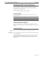
Disabling IP ARP Cache Refreshing ...................................................................20
Command Reference Updates .................................................................. 20
DHCP Option 82 Relay ..................................................................................... 22
Command Reference Updates .................................................................. 23
IGMP Enhancements ........................................................................................ 28
Fast Leave ................................................................................................ 28
Filtering and Throttling ............................................................................. 29
Command Reference Updates .................................................................. 32
OSPF Network Types ........................................................................................ 41
Command Reference Updates .................................................................. 43
BGP Enhancements .......................................................................................... 46
Changes to Algorithm for Determining the Best Route ............................. 46
Automatic Summarising: Advertising as Few Routes as Possible ................ 48
Importing and Advertising the Default Route ............................................ 51
Command Reference Updates .................................................................. 52
Classifying According to the Layer 5 Byte ......................................................... 57
Command Reference Updates .................................................................. 58
Firewall Enhancements ..................................................................................... 63
Increased Number of Firewall Policy Rules ................................................. 63
SIP Application Layer Gateway Diagnostic Tools ........................................ 63
UDP Port Timeout .................................................................................... 65
Command Reference Updates .................................................................. 66
WAN Load Balancing .......................................................................................74
VRRP Preemption Delay ....................................................................................75
Command Reference Updates .................................................................. 76
2
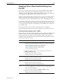
Introduction
Release Note
Introduction
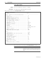
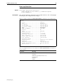
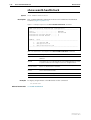
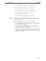
Allied Telesyn announces the release of Software Version 2.7.5 on the products
shown in Table 1. This Release Note describes all new features in Software
Version 2.7.5. The product series that each feature and enhancement applies to
are shown in “Overview of New Features” on page 4.
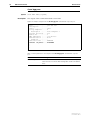
Table 1: Products supported by Software Version 2.7.5
Product series
Models
AT-9900
AT-9924T, AT-9924SP, AT-9924T/4SP
AT-8900
AT-8948
AT-9800
AT-9812T, AT-9816GB
Rapier i
Rapier 24i, Rapier 48i, Rapier 16fi
AT-8800
AT-8824, AT-8848
AT-8700XL
AT-8724XL, AT-8748XL
AT-8600
AT-8624T/2M, AT-8624PoE
AR700
AR725, AR745, AR750S
AR400
AR440S, AR441S, AR450S
This Release Note should be read in conjunction with the Installation and
Safety Guide or Quick Install Guide, Hardware Reference, and Software
Reference for your switch or router. These documents can be found on the
Documentation and Tools CD-ROM packaged with your switch or router, or:
www.alliedtelesyn.com/support/software
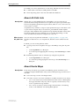
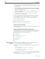
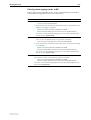
This Release Note has the following sections:
1.
Upgrading to Software Version 2.7.5
This section lists the file names that may be downloaded from the web site.
2.
Description of New Features in Software Version 2.7.5
This section lists the features that are new for Software Version 2.7.5 and
describes how to configure them.
3.
WAN Load Balancing
This section contains a copy of the complete WAN Load Balancing chapter.
WAN load balancing is newly supported on AR400 series routers, and the
balancing methods have been substantially extended.
4.
Filtering IP Routes
This section contains a copy of the new Filtering IP Routes chapter. This
chapter collects all existing information about filtering IP routes together
into one place. It describes when and how to filter routes, and how the
different routing protocols work together.
Caution: Information in this document is subject to change without notice and
does not represent a commitment on the part of Allied Telesyn Inc. While every
effort has been made to ensure that the information contained within this
document and the features and changes described are accurate, Allied Telesyn
Inc. can not accept any type of liability for errors in, or omissions arising from,
the use of this information.
Software Version 2.7.5
C613-10454-00 REV A
Software Version 2.7.5
3
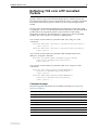
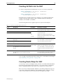
Upgrading to Software Version 2.7.5
Software Version 2.7.5 is available as a flash release that can be downloaded
directly from the Software/Documentation area of the Allied Telesyn website:
www.alliedtelesyn.com/support/software
Software versions must be licenced and require a password to activate. If you
upgrade to Software Version 2.7.5 from any 2.7.x version, your existing licence
is valid for 2.7.5. Otherwise, to obtain a licence and password, contact your
authorised Allied Telesyn distributor or reseller.
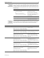
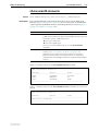
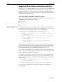
Table 2: File names for Software Version 2.7.5
Product name
Release file
GUI resource file
CLI help file
AT-9924T
89-275.rez
d9924e24.rsc
99-275a.hlp
AT-9924SP
89-275.rez
d9924e24.rsc
99-275a.hlp
AT-9924T/4SP
89-275.rez
d9924e24.rsc
99-275a.hlp
AT-8948
89-275.rez
—
89-275a.hlp
AT-9812T
sb-275.rez
d9812e24.rsc
98-275a.hlp
AT-9816GB
sb-275.rez
d9816e24.rsc
98-275a.hlp
Rapier 24i
86s-275.rez
dr24ie24.rsc
rp-275a.hlp
Rapier 48i
86s-275.rez
dr48ie24.rsc
rp-275a.hlp
Rapier16fi
86s-275.rez
dr16ie24.rsc
rp-275a.hlp
AT-8824
86s-275.rez
d8824e24.rsc
88-275a.hlp
AT-8848
86s-275.rez
d8848e24.rsc
88-275a.hlp
AT-8724XL
87-275.rez
d8724e24.rsc
87-275a.hlp
AT-8748XL
87-275.rez
d8748e24.rsc
87-275a.hlp
AT-8624PoE
sr-275.rez
—
86-275a.hlp
AT-8624T/2M
sr-275.rez
dsr24e24.rsc
86-275a.hlp
AR750S
55-275.rez
d750se24.rsc
700-275a.hlp
AR725
52-275.rez
d_725e24.rsc
700-275a.hlp
AR745
52-275.rez
d_745e24.rsc
700-275a.hlp
AR440S
54-275.rez
d440se24.rsc
400-275a.hlp
AR441S
54-275.rez
d441se24.rsc
400-275a.hlp
AR450S
54-275.rez
d450se24.rsc
400-275a.hlp
Software Version 2.7.5
C613-10454-00 REV A
4
Overview of New Features
Release Note
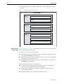
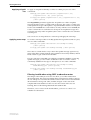
Overview of New Features
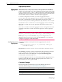
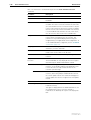
This section lists the new features and enhancements by product series. For
supported models, see Table 1 on page 2.
AT-9900
AT-8900
AT-9800
AT-8600
AT-8700XL
AT-8800
Rapier
AR750S
AR7x5
AR400
Table 3: New features and enhancements in Software Version 2.7.5
MSS Clamping
! ! ! ! !
! ! !
Reflecting TOS onto L2TP-tunnelled Packets
! ! ! ! !
! ! !
Switch Ports: Fixed Speed and Autonegotiated Duplex Mode
!
! ! ! ! ! ! ! !
!a
Switch Ports: Fixed 1000Mbps Full Duplex Mode
!a
!a !a !
Disabling IP ARP Cache Refreshing
! ! ! ! ! ! ! ! ! !
DHCP Option 82 Relay
! ! ! ! ! ! ! ! ! !
IGMP: Fast Leave
! ! ! ! ! ! ! ! ! !
IGMP: Filtering and Throttling
! ! ! ! ! ! ! ! ! !
OSPF Network Types
! ! ! ! ! ! ! ! ! !
BGP: Changes to Algorithm for Determining the Best Route
! ! ! ! !
! ! !
BGP: Automatic Summarising: Advertising as Few Routes as
Possible
! ! ! ! !
! ! !
BGP: Importing and Advertising the Default Route
! ! ! ! !
! ! !
! !
Classifying According to the Layer 5 Byte
Firewall: Increased Number of Firewall Policy Rules
! ! ! ! !
! !
Firewall: SIP Application Layer Gateway Diagnostic Tools
! ! ! ! !
! !
Firewall: UDP Port Timeout
! ! ! ! !
! !
Support for WAN Load Balancing
!
!a
New Balancing Methods for WAN Load Balancing
!
!
VRRP Preemption Delay
! ! ! ! ! ! ! ! ! !
a. Also supported by earlier releases on some or all models in this series
Software Version 2.7.5
C613-10454-00 REV A
Software Version 2.7.5
5
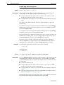
MSS Clamping
Maximum Segment Size (MSS) clamping functionality has been introduced to
Point-to-Point Protocol (PPP) to allow the following:
■
User configuration of the MSS clamping value via the command line
interface.
■
A clamping range of 40 - 200 bytes.
Previously, MSS clamping occurred at a fixed value of 120 bytes.
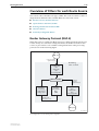
Overview
MSS clamping reserves a set amount of space within a TCP packet for the
header, which in turn limits the amount of space that may be consumed by the
data (payload). Setting the header space value to an appropriate level prevents
packet fragmentation from occurring.
Maximum
Transmission Unit and
Maximum Segment
Size
The Maximum Transmission Unit (MTU) is the maximum number of bytes per
packet that may be transmitted by the network interface. If a single packet
exceeds the MTU, it is divided into smaller packets before being transmitted.
For a TCP packet, the MTU can be illustrated by the following equation:
MTU = Header Size + Maximum Segment Size
where:
■
Header Size is the size of the packet header
■
Maximum Segment Size is the largest amount of TCP data, in bytes, that
the router or switch can transmit or receive in one single data packet.
MTU is set with the set interface mtu command. For more information, see the
Interfaces chapter of the Software Reference.
Data Transmission and
MSS clamping
As packets are sent across various protocols, each protocol adds its own header
and encapsulates the information. This can increase the size of the packet being
transmitted, potentially exceeding the MTU of devices on the TCP/IP link.
When the packet exceeds the defined MTU for an interface, fragmentation
occurs. Packet fragmentation can be costly for the following reasons:
■
decreased throughput, the amount of data transferred or processed in a
specified amount of time
■
networks that are explicitly set to drop fragmented packets suffer
communication loss.
Each TCP device uses its MSS value to communicate the highest allowable
amount of data it can receive. Although devices in a TCP/IP connection
calculate the amount of data to send in a packet based on variables, such as the
current window size and various algorithms, the amount of actual data can
never exceed the MSS of the device the packet is being sent to.
Setting the MSS clamping value at an appropriate limit prevents fragmentation
by reserving a set amount of space within a TCP packet for the header, so that
the packet nver needs to be fragmented at any point in its journey. Allowing
header space, in turn, limits the amount of space that may be consumed by the
data payload.
Software Version 2.7.5
C613-10454-00 REV A
6
MSS Clamping
Release Note
Example
If the MTU of a PPP interface is 1000 bytes, and you wish to limit the MSS to
850 bytes, use the command:
set ppp=0 mssheader=150
By setting the mssheader parameter to 150 bytes, this amount of space is
reserved for the header. If the MTU is 1000, then this leaves 850 bytes of
available space in the packet for data.
Command changes
The following table summarises the modified commands (see Command
Reference Updates).
Command
Change
create ppp
New mssheader parameter
set ppp
New mssheader parameter
create ppp template
New mssheader parameter
set ppp template
New mssheader parameter
show ppp template
New Maximum Segment Size field
show ppp pppoe
New Clamped MSS Header Size (bytes) field
Software Version 2.7.5
C613-10454-00 REV A
Software Version 2.7.5
7
Command Reference Updates
This section describes the changed portions of modified commands and output
screens. For modified commands and output, new parameters and fields are
shown in bold.
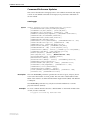
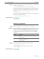
create ppp
Syntax
CREate PPP=ppp-interface OVER=physical-interface
[AUTHENTICATION={CHAP|EITHER|PAP|NONE}]
[AUTHMODE={IN|OUT|INOUT}] [BAP={ON|OFF}]
[BAPMODE={CALL|CALLBACK}] [CBDELAY=1..100]
[CBMODE={ACCEPT|OFF|REQUEST}] [CBNUMBER=e164number]
[CBOPERATION={E164NUMBER|USERAUTH}]
[COMPALGORITHM={PREDICTOR|STACLZS}]
[COMPRESSION={ON|OFF|LINK}]
[CONFIGURE={value|CONTINUOUS}] [DEBUGMAXBYTES=16..256]
[DESCRIPTION=description] [DOWNRATE=0..100]
[DOWNTIME=time] [ECHO={ON|OFF|period}]
[ENCRYPTION={ON|OFF}] [FRAGMENT={ON|OFF}]
[FRAGOVERHEAD=0..100] [IDLE={ON|OFF|time}]
[INDATALIMIT={NONE|1..65535}] [IPPOOL={pool-name|NONE}]
[IPREQUEST={ON|OFF}] [LQR={ON|OFF|period}]
[MAGIC={ON|OFF}] [MODEM={ON|OFF}]
[MRU={ON|OFF|256..1656}] [MSSheader=40..200]
[NULLFRAGTIMER=time] [NUMBER=number]
[ONLINELIMIT={NONE|1..65535}]
[OUTDATALIMIT={NONE|1..65535}] [PASSWORD=password]
[PREDCHECK={CRC16|CRCCCITT}]
[RECHALLENGE={ON=|OFF|360..3600}] [RESTART=time]
[STACCHECK={LCB|SEQUENCE}] [STARENTITY=1..255]
[TERMINATE={value|CONTINUOUS}]
[TOTALDATALIMIT={NONE|1..65535}]
[TYPE={DEMAND|PRIMARY|SECONDARY}] [UPRATE=0..100]
[UPTIME=time] [USERNAME=username]
Description
The new mssheader parameter specifies the amount of space, in bytes, that is
reserved for the header of a TCP packet. This amount is subtracted from the
MTU of the interface to define the Maximum Segment Size (MSS). The default
is 120 bytes.
The mssheader parameter may only be used with an Ethernet or VLAN
physical interface (PPPoE).
Examples
To create a PPPoE interface that has a default MTU of 1492 with an MSS value
of 1292, use the command:
cre ppp=0 over=eth0-any mssheader=200
Software Version 2.7.5
C613-10454-00 REV A
8
MSS Clamping
Release Note
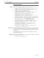
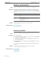
create ppp template
Syntax
CREate PPP TEMPlate=template [COPY=template]
[AUTHENTICATION={CHAP|EITHER|PAP|NONE}] [BAP={ON|OFF}]
[BAPMODE={CALL|CALLBACK}] [CBDELAY=1..100]
[CBMODE={ACCEPT|OFF|REQUEST}] [CBNUMBER=e164number]
[CBOPERATION={E164NUMBER|USERAUTH}]
[COMPALGORITHM={PREDICTOR|STACLZS}]
[COMPRESSION={ON|OFF|LINK}] [DEBUGMAXBYTES=16..256]
[DESCRIPTION=description] [DOWNRATE=0..100]
[DOWNTIME=time] [ECHO={ON|OFF|period}]
[ENCRYPTION={ON|OFF}] [FRAGMENT={ON|OFF}]
[FRAGOVERHEAD=0..100] [IDLE={ON|OFF|time}]
[INDATALIMIT={NONE|1..65535}] [IPPOOL={pool-name|NONE}]
[IPREQUEST={ON|OFF}] [LOGIN={ALL|RADIUS|TACACS|USER}]
[LQR={ON|OFF|period}] [MAGIC={ON|OFF}] [MAXLINKS=1..64]
[MRU={ON|OFF|256..1656}] [MSSheader=40..200]
[MTU=256..1500|256..1492] [MULTILINK={ON|OFF}]
[NULLFRAGTIMER=time] [ONLINELIMIT={NONE|1..65535}]
[OUTDATALIMIT={NONE|1..65535}] [PASSWORD=password]
[PREDCHECK={CRC16|CRCCCITT}]
[RECHALLENGE={ON|OFF|360..3600}] [RESTART=time]
[STACCHECK={LCB|SEQUENCE}] [STARENTITY=1..255]
[TERMINATE={value|CONTINUOUS}]
[TOTALDATALIMIT={NONE|1..65535}] [UPRATE=0..100]
[UPTIME=time] [USERNAME=username]
Description
The new mssheader parameter specifies the amount of space, in bytes, that is
reserved for the header of a TCP packet. This amount is subtracted from the
MTU of the interface to define the Maximum Segment Size (MSS). The default
is 120 bytes.
The mssheader parameter may only be used with an Ethernet or VLAN
physical interface (PPPoE).
Examples
To create a PPPoE template that uses the default MTU of 1000 and has an MSS
value of 800, use the command:
cre ppp temp=1 mssheader=200
Software Version 2.7.5
C613-10454-00 REV A
Software Version 2.7.5
9
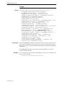
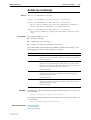
set ppp
Syntax
SET PPP==ppp-interface [OVER=physical-interface]
[AUTHENTICATION={CHAP|EITHER|PAP|NONE}]
[AUTHMODE={IN|OUT|INOUT}] [BAP={ON|OFF}]
[BAPMODE={CALL|CALLBACK}] [CBDELAY=1..100]
[CBMODE={ACCEPT|OFF|REQUEST}] [CBNUMBER=e164number]
[CBOPERATION={E164NUMBER|USERAUTH}]
[COMPALGORITHM={PREDICTOR|STACLZS}]
[COMPRESSION={ON|OFF|LINK}]
[CONFIGURE={value|CONTINUOUS}] [DEBUGMAXBYTES=16..256]
[DESCRIPTION=description] [DOWNRATE=0..100]
[DOWNTIME=time] [ECHO={ON|OFF|period}]
[ENCRYPTION={ON|OFF}] [FRAGMENT={ON|OFF}]
[FRAGOVERHEAD=0.100] [IDLE={ON|OFF|time}]
[INDATALIMIT={NONE|1..65535}] [IPPOOL={pool-name|NONE}]
[IPREQUEST={ON|OFF}] [LQR={ON|OFF|period}]
[MAGIC={ON|OFF}] [MAXLINKS=1..64] [MODEM={ON|OFF}]
[MRU={ON|OFF|256..1656}] [MSSheader=40..200]
[NULLFRAGTIMER=time] [ONLINELIMIT={NONE|1..65535}]
[OUTDATALIMIT={NONE|1..65535}] [PASSWORD=password]
[PREDCHECK={CRC16|CRCCCITT}]
[RECHALLENGE={ON|OFF|360..3600}] [RESTART=time]
[STACCHECK={LCB|SEQUENCE}] [STARENTITY=1..255]
[TERMINATE={value|CONTINUOUS}]
[TOTALDATALIMIT={NONE|1..65535}]
[TYPE={DEMAND|PRIMARY|SECONDARY}] [UPRATE=0..100]
[UPTIME=time] [USERNAME=username]
Description
The new mssheader parameter specifies the amount of space, in bytes, that is
reserved for the header of a TCP packet. This amount is subtracted from the
MTU of the interface to define the Maximum Segment Size (MSS). The default
is 120 bytes.
The mssheader parameter may only be used with an Ethernet or VLAN
physical interface (PPPoE).
Examples
To set a PPPoE interface that has a default MTU of 1492 to use an MSS value of
1292, use the command:
set ppp=0 over=eth0-any mssheader=200
Software Version 2.7.5
C613-10454-00 REV A
10
MSS Clamping
Release Note
set ppp template
Syntax
SET PPP TEMPlate=template
[AUTHENTICATION={CHAP|EITHER|PAP|NONE}] [BAP={ON|OFF}]
[BAPMODE={CALL|CALLBACK}] [CBDELAY=1..100]
[CBMODE={ACCEPT|OFF|REQUEST}] [CBNUMBER=e164number]
[CBOPERATION={E164NUMBER|USERAUTH}]
[COMPALGORITHM={PREDICTOR|STACLZS}]
[COMPRESSION={ON|OFF|LINK}] [DEBUGMAXBYTES=16..256]
[DESCRIPTION=description] [ECHO={ON|OFF|period}]
[ENCRYPTION={ON|OFF}] [FRAGMENT={ON|OFF}]
[FRAGOVERHEAD=0..100] [IDLE={ON|OFF|time}]
[INDATALIMIT={NONE|1..65535}] [IPPOOL={pool-name|NONE}]
[IPREQUEST={ON|OFF}] [LOGIN={ALL|RADIUS|TACACS|USER}]
[LQR={ON|OFF|period}] [MAGIC={ON|OFF}] [MAXLINKS=1..64]
[MRU={ON|OFF|256..1656}] [MSSheader=40..200]
[MTU=256..1500|256..1492] [MULTILINK={ON|OFF}]
[NULLFRAGTIMER=time] [ONLINELIMIT={NONE|1..65535}]
[OUTDATALIMIT={NONE|1..65535}] [PASSWORD=password]
[PREDCHECK={CRC16|CRCCCITT}]
[RECHALLENGE={ON|OFF|360..3600}] [RESTART=time]
[STACCHECK={LCB|SEQUENCE}] [STARENTITY=1..255]
[TOTALDATALIMIT={NONE|1..65535}] [USERNAME=username]
Description
The new mssheader parameter specifies the amount of space, in bytes, that is
reserved for the header of a TCP packet. This amount is subtracted from the
MTU of the interface to define the Maximum Segment Size (MSS). The default
is 120 bytes.
The mssheader parameter may only be used with an Ethernet or VLAN
physical interface (PPPoE).
Examples
To set a PPPoE template that has an MSS value of 800, use the command:
set ppp temp=1 mssheader=200
Software Version 2.7.5
C613-10454-00 REV A
Software Version 2.7.5
11
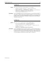
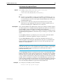
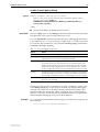
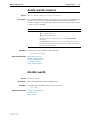
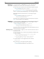
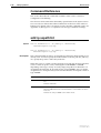
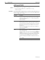
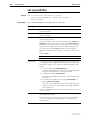
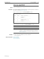
show ppp pppoe
Syntax
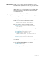
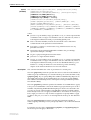
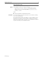
Description
SHow PPP PPPoe
The output of this command includes a new field.
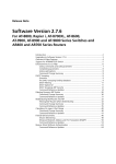
Figure 1: Example output from the show ppp pppoe command
PPPOE
-----------------------------------------------------------PPP1:
Service Name ................. bob
Peer Mac Address ............. 00-00-cd-00-ab-a3
Session ID ................... a1a3
Maximum Segment Size ......... 1292
Access Concentrator Mode ..... Enabled
Services:
bob
Max sessions ................
Current Sessions ............
Template ....................
MAC RADIUS Authentication ...
carol
Max sessions ................
Current Sessions ............
Template ....................
MAC RADIUS Authentication ...
2
1
1
YES
5
0
1
YES
PPPOE Counters:
Rejected PADI packets ...... 0
Rejected PADO packets ...... 0
Rejected PADR packets ...... 0
Rejected PADS packets ...... 0
Rejected PADT packets ...... 0
-----------------------------------------------------------
Table 4: New parameters in the output of the show ppp pppoe command
Software Version 2.7.5
C613-10454-00 REV A
Parameter
Meaning
Maximum Segment Size
The maximum number of bytes that the data payload may
occupy in a TCP packet. This figure is derived by subtracting
the clamped MSS header size from the MTU of the interface
12
MSS Clamping
Release Note
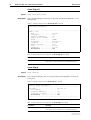
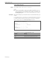
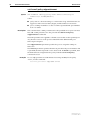
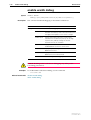
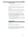
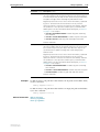
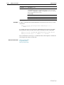
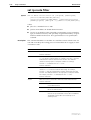
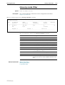
show ppp template
Syntax
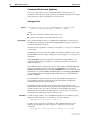
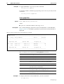
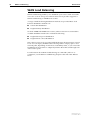
Description
SHow PPP TEMPLATE[=template] [DEBUG]
The output of this command includes a new field.
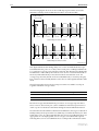
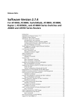
Figure 2: Example output from the show ppp template command
Template - Description
Parameter
Value
------------------------------------------------------------------------------pppt0 - Template for calls from Head Office
Multilink ......................................... ON
Maximum links ..................................... 4
Bandwidth Allocation Protocol ..................... ON
Bandwidth Allocation Call Mode .................... CALL
Multilink fragmentation ........................... OFF
Acceptable Fragment Overhead (%)................... 5
Null Fragment Timer (seconds)...................... 3
Idle Timer (seconds)............................... OFF
Compression ....................................... ON
Compression Algorithm ............................. STACLZS
Compression Checkmode ............................. LCB
Encryption ........................................ OFF
Username ......................................... NOT SET
Password .......................................... NOT SET
Login Servers ..................................... RADIUS,TACACS,USER
IP Pool ........................................... NOT SET
Request IP Address ................................ NO
VJC ............................................... OFF
Clamped MSS Header Size (bytes) ................... 200
Link
Authentication .................................... NONE
CHAP Rechallenge (max. period seconds)............. 900
Callback Mode ..................................... OFF
Callback Operation ................................ USER
Callback Number ................................... Callback Delay (seconds)........................... 5
Echo Timer (seconds)............................... 10
LQR Timer (seconds)................................ 60
Magic Number ...................................... ON
Maximum Receive Unit .............................. OFF
Restart Timer (seconds) ........................... 3
Debug
Maximum packet bytes to display ................... 32
-------------------------------------------------------------------------------
Table 5: New parameters in the output of the show ppp template command
Parameter
Meaning
Clamped MSS Header Size
The amount of space, in bytes, that is reserved for the
header of a TCP packet. This amount is subtracted from the
MTU of the interface to define the Maximum Segment Size
(MSS).
Software Version 2.7.5
C613-10454-00 REV A
Software Version 2.7.5
13
Reflecting TOS onto L2TP-tunnelled
Packets
Quality of Service (QoS) for L2TP-tunnelled packets on VPN networks has
been enhanced. Software Version 2.7.5 enables the router or switch to reflect the
TOS/DSCP field of the IP packet’s header onto the encapsulating L2TP IP
header.
The IP packet’s TOS/DSCP field indicates the desired QoS for the IP packet.
Copying this onto the encapsulating L2TP IP header means that the tunnelled
packet reflects the original IP packet’s QoS information. Networking
equipment can then use this information to apply QoS to the encapsulated
packet in the same way they would to the original packet.
You can turn on this feature for particular L2TP calls, using one of the
commands:
ADD L2TP CALL=name [TOSreflect={ON|OFF|Yes|No|True|False}]
[other-options...]
SET L2TP CALL=name [TOSreflect={ON|OFF|Yes|No|True|False}]
[other-options...]
You can turn on this feature for particular L2TP tunnel destination IP
addresses, using the command:
ADD L2TP IP=ipadd[-ipadd] PPPTemplate=ppp-template
[TOSreflect={ON|OFF|Yes|No|True|False}]
[other-options...]
You can turn on this feature for particular L2TP users, using one of the
commands:
ADD L2TP USer={mapping|ALL|LOCAL|NONE|REMote}
[TOSreflect={ON|OFF|Yes|No|True|False}]
[other-options...]
SET L2TP USER={mapping|ALL|LOCAL|NONE|REMote}
[TOSreflect={ON|OFF|Yes|No|True|False}]
[other-options...]
Command changes
The following table summarises the modified commands (see Command
Reference Updates).
Software Version 2.7.5
C613-10454-00 REV A
Command
Change
add l2tp call
New tosreflect parameter
set l2tp call
New tosreflect parameter
show l2tp call
New tosreflect field
add l2tp ip
New tosreflect parameter
show l2tp ip
New tosreflect field
add l2tp user
New tosreflect parameter
set l2tp user
New tosreflect parameter
show l2tp user
New tosreflect field
14
Reflecting TOS onto L2TP-tunnelled Packets
Release Note
Command Reference Updates
This section describes the changed portions of modified commands and output
screens. For modified commands and output, new parameters and fields are
shown in bold.
add l2tp call
Syntax
ADD L2TP CALL=name TYpe={ASYNc|ISDN|VIrtual} IP=ipadd
REMotecall=name [DIAL=number] [NUMber={ON|OFF|STARTup}]
[PASSword=password] [PRE13={ON|OFF}]
[PRECedence={IN|OUT}] [SPeed=speed]
[SUBAddress=subaddress]
[TOSreflect={ON|OFF|Yes|No|True|False}]
Description
The new tosreflect parameter specifies whether or not the TOS/DSCP field of a
data packet within the L2TP tunnel should be reflected onto the encapsulated
packet. This means that the tunnelled packet reflects the original packet’s QoS
information. The values on, yes, and true are equivalent. The values off, no,
and false are equivalent.
add l2tp ip
Syntax
Description
ADD L2TP IP=ipadd[-ipadd] PPPTemplate=ppp-template
[NUMber={ON|OFF|STARTup}] [PRE13={ON|OFF}]
[TOSreflect={ON|OFF|Yes|No|True|False}]
The new tosreflect parameter specifies whether or not the TOS/DSCP field of a
data packet within the L2TP tunnel should be reflected onto the encapsulated
packet. This means that the tunnelled packet reflects the original packet’s QoS
information. The values on, yes, and true are equivalent. The values off, no,
and false are equivalent.
add l2tp user
Syntax
Description
ADD L2TP USer={mapping|ALL|LOCAL|NONE|REMote}
ACtion={DATABase|DNSLookup|IGNore|RADius}
[IP=ipadd [POrt=port]] [NUMber={ON|OFF}]
[PASSword=password] [PRE13={ON|OFF}] [PREFix=prefix]
[TIMEOut=timeout]
[TOSreflect={ON|OFF|Yes|No|True|False}]
The new tosreflect parameter specifies whether or not the TOS/DSCP field of a
data packet within the L2TP tunnel should be reflected onto the encapsulated
packet. This means that the tunnelled packet reflects the original packet’s QoS
information. The values on, yes, and true are equivalent. The values off, no,
and false are equivalent.
Software Version 2.7.5
C613-10454-00 REV A
Software Version 2.7.5
15
set l2tp call
Syntax
SET L2TP CALL=name [DIAL=number] [IP=ipadd]
[NUMber={ON|OFF|STARTup}] [PASSword=password]
[PRE13={ON|OFF}] [PRECedence={IN|OUT}]
[REMotecall=name] [SPeed=speed] [SUBAddress=subaddress]
[TOSreflect={ON|OFF|Yes|No|True|False}]
[TYpe={ASYNc|ISDN|VIrtual}]
Description
The new tosreflect parameter specifies whether or not the TOS/DSCP field of a
data packet within the L2TP tunnel should be reflected onto the encapsulated
packet. This means that the tunnelled packet reflects the original packet’s QoS
information. The values on, yes, and true are equivalent. The values off, no,
and false are equivalent.
set l2tp user
Syntax
Description
Software Version 2.7.5
C613-10454-00 REV A
SET L2TP USer={mapping|ALL|LOCAL|NONE|REMote}
[ACtion={DATABase|DNSLookup|IGNore|RADius}]
[IP=ipadd [POrt=port]] [NUMber={ON|OFF}]
[PASSword=password] [PRE13={ON|OFF}] [PREFix=prefix]
[TIMEOut=timeout]
[TOSreflect={ON|OFF|Yes|No|True|False}]
The new tosreflect parameter specifies whether or not the TOS/DSCP field of a
data packet within the L2TP tunnel should be reflected onto the encapsulated
packet. This means that the tunnelled packet reflects the original packet’s QoS
information. If you specify on, yes or true, the TOS/DSCP field is reflected. If
you specify off, no or false the TOS/DSCP field is not reflected.
16
Reflecting TOS onto L2TP-tunnelled Packets
Release Note
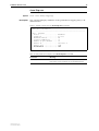
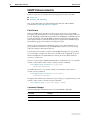
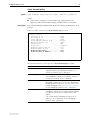
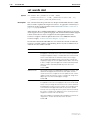
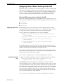
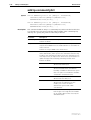
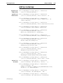
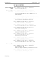
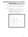
show l2tp call
Syntax
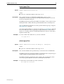
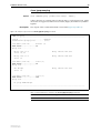
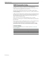
Description
SHow L2TP CALL[=name]
This command displays information about the specified call definition or all
defined calls.
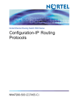
Figure 3: Example output from the show l2tp call command
L2TP Call Information
-----------------------------------------------------------Name : test
Type .................... virtual
Precedence .............. out
Sequence numbering ...... off
Remote is pre draft13 ... on
Speed ................... 64000
IP address .............. 192.168.1.2
Password ................ not set
Remote callname ......... test
Dial .................... not set
Subaddress .............. not set
ToS Reflect ............. off
Table 6: New parameter in the output of the show l2tp call command
Parameter
Meaning
ToS Reflect
Whether the TOS/DSCP field of data packets within the
L2TP tunnel is reflected onto the encapsulated packet.
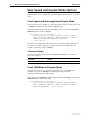
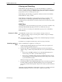
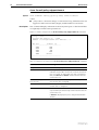
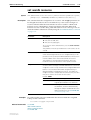
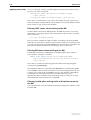
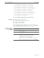
show l2tp ip
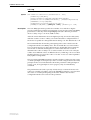
Syntax
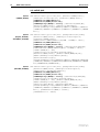
Description
SHow L2TP IP
This command displays the associations between PPP templates and remote
L2TP peers.
Figure 4: Example output from the show l2tp ip command
L2TP IP Range Information
-----------------------------------------------------------IP Range ........................ 192.168.1.2
PPP template .................. 1
Sequence numbering ............ off
Pre-draft 13 support .......... off
ToS Reflect ................... off
------------------------------------------------------------
Table 7: New parameter in the output of the show l2tp ip command
Parameter
Meaning
ToS Reflect
Whether the TOS/DSCP field of data packets within the
L2TP tunnel is reflected onto the encapsulated packet.
Software Version 2.7.5
C613-10454-00 REV A
Software Version 2.7.5
17
show l2tp user
Syntax
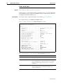
Description
SHow L2TP USER[=mapping]
This command displays attributes of the specified user mapping entry or all
defined entries.
Figure 5: Example output from the show l2tp user command
L2TP User Information
-----------------------------------------------------------User : dataman
Action ................... database
Password ................. not set
Maximum timeout .......... 20
Sequence Numbering ....... on
Remote is pre draft13 .... on
Remote IP ................ 192.168.1.2
Remote Port .............. 1701
ToS Reflect .............. off
Table 8: New parameter in output of the show l2tp user command
Software Version 2.7.5
C613-10454-00 REV A
Parameter
Meaning
ToS Reflect
Whether the TOS/DSCP field of data packets within the
L2TP tunnel is reflected onto the encapsulated packet.
18
New Speed and Duplex Mode Options
Release Note
New Speed and Duplex Mode Options
Software Version 2.7.5 extends the speed and duplex mode options for switch
ports.
Fixed Speed and Autonegotiated Duplex Mode
Software Version 2.7.5 enables you to fix the speed of copper switch ports to 10
or 100Mbps and still autonegotiate the duplex mode.
To fix the speed and autonegotiate the duplex mode, use the new 10mauto or
100mauto options in the command:
set switch port={port-list|all}
speed={autonegotiate|10mauto|10mhauto|10mhalf|10mfauto|
10mfull|100mauto|100mhauto|100mhalf|100mfauto|100mfull|
1000mhauto|1000mhalf|1000mfauto|1000mfull}
[other-options...]
The options that apply depend on the router or switch model and the type of
port. The new options apply to all copper switch ports and SFPs that are
capable of operating at 10 or 100Mbps.
Command Changes
The following table summarises the modified command (see Command
Reference Updates)
Command
Change
set switch port
New 10mauto and 100mauto options
Fixed 1000Mbps Full Duplex Mode
Software Version 2.7.5 also enables you to force ports on AT-9900 series
switches to operate at 1000Mbps in full duplex mode, instead of
autonegotiating with their link partners.
To fix the speed at 1000 Mbps and the duplex mode at full duplex, use the new
1000mfull option in the command:
set switch port={port-list|all}
speed={autonegotiate|10mauto|10mhauto|10mhalf|10mfauto|
10mfull|100mauto|100mhauto|100mhalf|100mfauto|100mfull|
1000mfull|1000mfauto} [other-options...]
Software Version 2.7.5
C613-10454-00 REV A
Software Version 2.7.5
19
For different types of port on AT-9900 series switches, the valid speed options
are shown in the following table.
Port type
RJ-45 copper ports
Speed parameter options
autonegotiate
10mauto, 10mhauto, 10mhalf, 10mfauto, 10mfull
100mauto, 100mhauto, 100mhalf, 100mfauto, 100mfull
1000mfull, 1000mfauto
copper SFPs
autonegotiate
10mauto, 10mhauto, 10mhalf, 10mfauto, 10mfull
100mauto, 100mhauto, 100mhalf, 100mfauto, 100mfull
1000mfull, 1000mfauto
fibre SFPs
autonegotiate
1000mfull, 1000mfauto
Command Changes
The following table summarises the modified command (see Command
Reference Updates)
Command
Change
set switch port
New 1000mfull option
Command Reference Updates
This section describes the modified command. The new options are shown in
bold.
set switch port
Syntax
Description
SET SWItch POrt={port-list|ALL}
[SPeed={AUTOnegotiate|10MAUTo|10MHAUto|10MHALf|
10MFAuto|10MFUll|100MAUto|100MHAUto|100MHALf|100MFAuto|
100MFUll|1000MHAUto|1000MHALf|1000MFAUto|1000MFUll}]
[other-options...]
On the speed parameter:
■
The new 10mauto option sets the port speed to 10Mbps. The port
autonegotiates the duplex mode.
■
The new 100mauto option sets the port speed to 100Mbps. The port
autonegotiates the duplex mode.
■
The new 1000mfull option sets the port speed to 1000Mbps and the duplex
mode to full duplex. The port uses this speed and duplex mode instead of
autonegotiating.
The speed and duplex mode options that apply depend on the router or switch
model and the type of port.
Software Version 2.7.5
C613-10454-00 REV A
20
Disabling IP ARP Cache Refreshing
Release Note
Disabling IP ARP Cache Refreshing
Software Release 2.7.5 enables you to disable IP ARP cache refreshing.
Previously, whenever an IP ARP entry was used (hit), the cache entry was
refreshed and the ageing timer reset.
To disable automatic refreshing, use the command
set ip arp refresharp={off|no|false}
Command Changes
The following table summarises the modified commands (see Command
Reference Updates)
Command
Change
set ip arp refresharp
New command
show ip
New field in output
Command Reference Updates
This section describes the new command and the changed portion of the
modified command output screen. For modified output, the new field is shown
in bold.
set ip arp refresharp
Syntax
Description
SET IP ARP REFresharp={ON|YES|True|OFF|NO|False}
This command specifies whether IP ARP entries are refreshed in the ARP cache
as they are used (hit).
The refresharp parameter specifies whether to refresh IP ARP entries in the
cache and restart the aging timer when an entry is used. The values on, yes
and true are equivalent. The values off, no and false are equivalent. The
default is on.
Software Version 2.7.5
C613-10454-00 REV A
Software Version 2.7.5
21
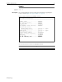
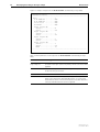
show ip
Syntax
Description
SHow IP
This command displays general configuration information regarding the
router or switch (Figure 6 on page 21, Table 9 on page 21).
Figure 6: Example output from the show ip command
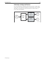
IP Module Configuration
-----------------------------------------------------------Module Status ..................
IP Packet Forwarding ...........
IP Echo Reply ..................
Debugging ......................
IP Fragment Offset Filtering ...
Default Name Servers
Primary Name Server ..........
Secondary Name Server ........
Name Server ....................
Secondary Name Server ..........
Source-Routed Packets ..........
Remote IP address assignment ...
DNS Relay ......................
IP ARP LOG .....................
IP ARP refresh by hit ..........
.
.
.
ENABLED
ENABLED
ENABLED
DISABLED
ENABLED
192.168.1.1 (ppp0)
Not Set
192.168.1.1 (ppp0)
Not Set
Discarded
DISABLED
DISABLED
ENABLED
ENABLED
Table 9: New parameter in output of the show ip command
Software Version 2.7.5
C613-10454-00 REV A
Parameter
Meaning
IP ARP refresh by hit
Whether ARP entry refreshing is enabled.
22
DHCP Option 82 Relay
Release Note
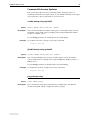
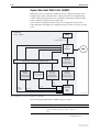
DHCP Option 82 Relay
The existing DHCP and BOOTP functionality has been enhanced to include the
addition, removal and monitoring of DHCP Option 82. Option 82 is also called
the Relay Agent Information option.
Option 82 is inserted by the DHCP relay agent into the DHCP options field
when forwarding client-originated BOOTP/DHCP packets to a DHCP server.
DHCP servers that are configured to recognise Option 82 may use the
information to implement IP addresses, or other parameter assignment
policies, based on the network location of the client device.
For more information about Option 82, see RFC 3046.
The BOOTP relay function has been enhanced. Option 82 can now be:
■
added to packets relayed from the DHCP client to DHCP server
■
removed from packets relayed from DHCP server to DHCP client
■
checked from sources closer to the client.
Additional commands have also been added to enable and disable Option 82.
Command changes
The following table summarises the new and modified commands (see
Command Reference Updates).
Command
Change
purge bootp relay
New result on entry of command.
show bootp relay
New DHCP Option 82 fields Insertion status,
Check, Reforwarding policy and
Debugging
enable bootp relay option82
New command
disable bootp relay option82
New command
set bootp relay option82
New command
set bootp relay option82 port
New command
show bootp relay port
New command
Software Version 2.7.5
C613-10454-00 REV A
Software Version 2.7.5
23
Command Reference Updates
This section describes each new command and the changed portions of
modified commands and output screens. For modified commands and output,
new parameters, options and fields are shown in bold.
enable bootp relay option82
Syntax
Description
ENAble BOOTp RELAy OPTion82 [DEBug]
This command enables the DHCP relay agent to insert DHCP Option 82 into
the DHCP options field when forwarding client-originated BOOTP/DHCP
packets to a DHCP server.
Use the debug parameter to enable Option 82 related debug.
Example
To enable the insertion of Option 82, use the command:
ena boot rela opt
disable bootp relay option82
Syntax
Description
DISable BOOTp RELAy OPTion82 [DEBug]
This command disables the insertion of DHCP Option 82 into the DHCP
options field when forwarding client-originated BOOTP/DHCP packets to a
DHCP server.
Use the debug parameter to disable Option 82 related debug.
Example
To disable the insertion of Option 82, use the command:
dis boot rela opt
purge bootp relay
Syntax
Description
Software Version 2.7.5
C613-10454-00 REV A
PURge BOOTp RELAy
This command now purges the BOOTP relay configuration. The BOOTP
module is disabled and all configuration data is purged.
24
DHCP Option 82 Relay
Release Note
set bootp relay option82
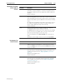
Syntax
Description
SET BOOTp RELAy OPTion82
[CHEck={YES|NO|ON|OFF|True|False}]
[POLIcy={DROP|KEEP|REPLACE}]
This command defines the checking and re-forwarding settings used by DHCP
Option 82. When Option 82 is enabled, the DHCP relay agent inserts Option 82
information into the DHCP options field when forwarding client-originated
BOOTP/DHCP packets to a DHCP server. Option 82 must be enabled with the
enable bootprelay option 82 command for the settings you specify to take
effect.
Use the check parameter to specify whether the Option 82 information that is
returned from the DHCP server is to be checked or not. When checking is
enabled, server DHCP packets that contain valid Option 82 information are
forwarded to the client, and packets that do not contain valid Option 82
information are dropped. If yes is specified, checking is enabled. The values
yes, on, and true are equivalent. If no is specified, Option 82 information
returned from the DHCP server is not checked. The values no, off, and false
are equivalent. The default is yes.
Use the policy parameter to specify the re-forwarding policy of client DHCP
packets that contain Option 82 information. If drop is specified, client DHCP
packets that contain Option 82 information are dropped. If keep is specified,
the packet keeps its existing Option 82 information. If replace is specified, the
existing Option 82 information is replaced with that of the local device. The
default is replace.
Example
To set the re-forwarding policy to drop client DHCP packets with Option 82
information, use the command:
set boot rela opt poli=drop
Software Version 2.7.5
C613-10454-00 REV A
Software Version 2.7.5
25
set bootp relay option82 port
Syntax
SET BOOTp RELAy OPTion82 POrt={port-list|ALL}
[SUBScriberid=subscriber-id]
[TRusted={YES|NO|ON|OFF|True|False}]
where:
Description
■
port-list is a port number, a range of port numbers (specified as n-m), or a
comma-separated list of port numbers and/or ranges. Port numbers start
at 1 and end at m, where m is the highest numbered Ethernet switch port,
including uplink ports.
■
subscriber-id is a character string from 0 to 50 characters long. Valid
characters are any alphanumeric characters. If string contains spaces, it
must be in double quotes. Wildcards are not allowed.
This command defines the DHCP Relay Agent port settings for DHCP Option
82. When Option 82 is enabled, the Relay Agent inserts Option 82 information
into the DHCP options field when forwarding client-originated
BOOTP/DHCP packets to a DHCP server. Option 82 must be enabled with the
enable bootprelay option 82 command for the port settings you specify to take
effect.
Use the port parameter to specify the port to use for this command. If all is
specified, this command is applied to all ports on the device.
Use the subscriberid parameter to specify the subscriber-ID for the port
defined in port=. If specified, the subscriber-ID sub-option is included in the
Option 82 field of client DHCP packets received on the specified port. The
default is no subscriber-ID.
NOTE If you specify an empty string in the subscriberid parameter, then the
subscriber-ID sub-option is not included in the Option 82 field of client DHCP
packets forwarded from the specified port. Use this method to delete a
subscriber-ID from a port.
Use the trusted parameter to specify how the router or switch handles client
DHCP packets that contain Option 82 information, but which have the giaddr
field set to 0. If you specify yes, the defined port is considered to be a trusted
source of Option 82 information, and packets with Option 82 information and a
giaddr of 0 are forwarded according to normal BOOTP Relay operation. The
values yes, on, and true are equivalent. If you specify no, packets are dropped
that contain DHCP Option 82 information and with the giaddr field set to 0.
The values no, off, and false are equivalent. The default is no.
Example
To set all ports as trusted, use the command:
set boot rela opt po=all tr=yes
Software Version 2.7.5
C613-10454-00 REV A
26
DHCP Option 82 Relay
Release Note
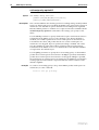
show bootp relay
Syntax
Description
SHow BOOTp RELAy
This command displays the current configuration of the BOOTP Relay Agent.
Figure 7: Example output from the show bootp relay command
BOOTP Relaying Agent Configuration.
Status ...................... Disabled
Maximum hops ................ 4
DHCP Option 82:
Insertion status ..........
Check .....................
Reforwarding policy .......
Debugging .................
Enabled
Yes
Replace
Disabled
BOOTP Relay Destinations
-----------------------------------------------------------No relay destinations configured...
-----------------------------------------------------------BOOTP Counters
InPackets ...............
InRejects ...............
InRequests ..............
InReplies ...............
0
0
0
0
OutPackets ................ 0
Table 10: New parameters in the output of the show bootp relay command
Parameter
Meaning
Insertion Status
The status of DHCP Option 82 insertion, either Enabled or
Disabled.
Check
Whether DHCP Option 82 information returned from the
DHCP server is being checked, either Yes or No.
Reforwarding policy
The re-forwarding policy of client DHCP packets, either
Replace, Keep, or Drop.
Debugging
The status of DHCP Option 82 debugging, either Enabled or
Disabled.
Software Version 2.7.5
C613-10454-00 REV A
Software Version 2.7.5
27
show bootp relay port
Syntax
SHow BOOTp RELAy POrt[={port-list|ALL}]
where:
■
Description
port-list is a port number, a range of port numbers (specified as n-m), or a
comma-separated list of port numbers and/or ranges. Port numbers start
at 1 and end at m, where m is the highest numbered Ethernet switch port,
including uplink ports.
This command displays port-related information about the BOOTP Relay port
settings.
Use the port parameter to specify the port to display BOOTP Relay information
for. If all is specified, information about all ports on the device is displayed.
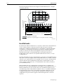
Figure 8: Example output from the show bootp relay port command
BOOTP Relay Port Information:
---------------------------------------Port .................... 1
Trusted .................... No
Subscriber-ID .............. user12332
Port .................... 2
Trusted ....................Yes
Subscriber-ID ..............
----------------------------------------
Table 11: Parameters in output of the show bootp relay command
Software Version 2.7.5
C613-10454-00 REV A
Parameter
Meaning
Port
The number of the switch port
Trusted
Whether the port is trusted, either Yes or No.
Subscriber-ID
The subscriber-ID assigned to the port.
28
IGMP Enhancements
Release Note
IGMP Enhancements
Software Version 2.7.5 includes the following enhancements for IGMP:
■
Fast Leave
■
Filtering and Throttling
This section describes each enhancement, then the new and modified
commands in Command Reference Updates.
Fast Leave
When an IGMP group-specific leave message is received on a port, IGMP
Snooping stops the transmission of the group multicast stream after a timeout
period. The lmqi (Last Member Query Interval) and lmqc (Last Member Query
Count) parameters of the set ip igmp command set the timeout period. This
timeout period allows other hosts on the port to register their membership of
the multicast group and continue receiving the stream.
The Fast Leave feature allows IGMP Snooping to stop the transmission of a
group multicast stream from a port immediately it receives a leave message,
without waiting for the timeout period.
Use the Fast Leave feature to improve bandwidth management on ports that
are connected to a single host. Fast Leave should not be configured on a port
that has multiple hosts attached because it may adversely affect multicast
services to some hosts.
Fast Leave processing is disabled by default. To enable Fast Leave on a specific
VLAN, or all VLANs on the router or switch, use the command:
set igmpsnooping fastleave={on|yes|true}
[interface=interface]
To disable Fast Leave on a specific VLAN, or all VLANs on the router or
switch, use the command:
set igmpsnooping fastleave={off|no|false}
[interface=interface]
To display the current state of Fast Leave processing on a specific VLAN, or all
VLANs on the router or switch, use the command:
show igmpsnooping [vlan={vlan-name|1..4094}]
Command Changes
The following table summarises the new and modified commands:
Command
Change
set igmpsnooping fastleave
New command
show igmpsnooping
New Fast Leave field
Software Version 2.7.5
C613-10454-00 REV A
Software Version 2.7.5
29
Filtering and Throttling
IGMP filtering and throttling let you control the distribution of multicast
services on each switch port. IGMP filtering controls which multicast groups a
host on a switch port can join. IGMP throttling limits the number of multicast
groups that a host on a switch port can join.
IGMP filtering and throttling are applied to multicast streams forwarded by
IGMP, IGMP Snooping, or MVR.
IGMP filtering and throttling can be applied separately, or together, on the
same switch port. Filtering is applied first, and any multicast group
memberships passed by the filter are further subjected to the limits imposed by
throttling.
IGMP Filters
An IGMP filter controls the multicast groups that a port can be a member of by
filtering IGMP Membership Reports from hosts attached to the port.
Static associations of switch ports and multicast groups are not affected by
IGMP filtering.
Format of a filter
An IGMP filter consists of zero or more entries. An entry consists of:
■
A multicast address range to match against. Address ranges in multiple
entries can overlap.
■
An action to take (include or exclude) when a Membership Report matches
the multicast address range.
Each filter has an implicit exclude entry as the last entry in the filter.
Matching against a
filter
When an IGMP filter is applied to a switch port:
1.
IGMP matches Membership Reports from the switch port against each
entry in the filter applied to the port.
2.
If the group address in the Membership Report matches the multicast
address range of a filter entry, IGMP takes the action specified by the filter
entry:
•
If the action is include, IGMP processes the Membership Report as
normal. The port is able to join the multicast group.
•
If the action is exclude, IGMP excludes the Membership Report from
normal IGMP processing and discards the packet. The port is not able
to join the multicast group.
Filter processing stops when a match is found.
3.
If the group address in the Membership Report does not match any entry in
the filter, IGMP excludes the Membership Report from normal IGMP
processing and discards the packet. The port is not able to join the multicast
group.
Applying an empty IGMP filter (a filter with no entries) to a switch port blocks
all Membership Reports because of the filter’s implicit exclude entry.
Software Version 2.7.5
C613-10454-00 REV A
30
IGMP Enhancements
Order of entries
Release Note
The order of entries in a filter is important. When IGMP tries to match a
Membership Report to a filter, it performs a linear search of the filter to find a
matching entry. Each entry is tried in turn, and processing stops at the first
match found.
Address ranges can overlap. If the address range of an entry falls entirely
within the address range of another entry, the entry with the smaller address
range should appear first in the filter. Otherwise it will never be matched
against a Membership Report.
Performance can be improved by arranging the entries in a filter to achieve the
earliest possible match.
Configuring IGMP
filters
To configure an IGMP filter, you must create the filter and then apply it to one
or more switch ports.
To do this, first create the filter, using the command:
create igmp filter=filter-id
Then add one or more entries to the filter, using the command:
add igmp filter=filter-id groupaddress=ipadd[-ipadd]
[action={include|exclude}] [entry=1..65535]
Finally, apply the filter to a switch port, using the command:
set switch port={port-list|all} igmpfilter=filter-id
[other-options...]
You can apply an IGMP filter to more than one switch port, but a single switch
port can have only one IGMP filter assigned to it.
To delete or modify an entry in a filter, use the commands:
delete igmp filter=filter-id entry=1..65535
set igmp filter=filter-id entry=1..65535
groupaddress=ipadd[-ipadd] action={include|exclude}
To remove a filter from a switch port, use the command:
set switch port={port-list|all} igmpfilter=none
[other-options...]
To destroy a filter, first remove the filter from all ports that it is applied to, then
use the command:
destroy igmp filter=filter-id
To display information about IGMP filters, use the command:
show igmp filter=filter-id
To display the IGMP filter assigned to a switch port, use the command:
show switch port[={port-list|all}]
Software Version 2.7.5
C613-10454-00 REV A
Software Version 2.7.5
31
IGMP Throttling
IGMP throttling controls the maximum number of multicast groups that a port
can join. When the number of multicast group memberships associated with a
switch port reaches the limit set, further Membership Reports are subject to a
throttling action—deny or replace.
If you configure a throttling action of deny, when the multicast group
membership associated with the port reaches the set limit, additional
Membership Reports from that switch port are denied until old membership
entries are aged out.
If you configure a throttling action of replace, when the multicast group
membership associated with the port reaches the set limit, additional
Membership Reports from that switch port replace existing membership
entries.
Static associations of switch ports and multicast groups are counted in the
number of multicast group memberships, but they are not affected by the
throttling action.
Configuring IGMP
throttling
To enable IGMP throttling on a switch port, set the maximum number of group
memberships and the throttling action to take, by using the command:
set switch port={port-list|all} igmpmaxgroup=1..65535
igmpaction={deny|replace} [other-options...]
To disable IGMP throttling on a switch port, set the maximum number of
group memberships to none, by using the command:
set switch port={port-list|all} igmpmaxgroup=none
[other-options...]
To display the IGMP throttling settings for a switch port, use the command:
show switch port[={port-list|all}]
Command Changes
The following table summarises the new and modified commands:
Command
Change
IGMP Filtering
add igmp filter
New command
create igmp filter
New command
delete igmp filter
New command
destroy igmp filter
New command
set igmp filter
New command
show igmp filter
New command
set switch port
New igmpfilter parameter
show switch port
New IGMP Filter field
IGMP Throttling
set switch port
New igmpmaxgroup parameter
New igmpaction parameter
show switch port
New Max-groups/Joined field
New IGMP Max-groups Action field
Software Version 2.7.5
C613-10454-00 REV A
32
IGMP Enhancements
Release Note
Command Reference Updates
This section describes each new command and the changed portions of
modified commands and output screens. For modified commands and output,
new parameters, options and fields are shown in bold.
add igmp filter
Syntax
ADD IGMP FILter=filter-id GROupaddress=ipadd[-ipadd]
[ACtion={INCLude|EXCLude}] [ENTry=1..65535]
where:
Description
■
filter-id is a decimal number in the range 1 to 99.
■
ipadd is an IP address in dotted decimal notation.
This command adds an entry to an IGMP filter. IGMP filters control a port’s
membership of multicast groups by filtering Membership Reports received
from hosts attached to the port.
The filter must be applied to a switch port using the set switch port command
to take effect.
The filter parameter specifies the number of the filter to add the entry to. The
specified filter must have been created previously using the create igmp filter
command.
The groupaddress parameter specifies an IP multicast group address, or a
range of IP multicast group addresses to match. The IP addresses must be
multicast addresses.
The action parameter specifies the action to take when an IGMP Membership
Report group address matches the value of groupaddress. If you specify
include, Membership Reports matching groupaddress are processed as normal
by IGMP. If you specify exclude, Membership Reports matching groupaddress
are excluding from processing by IGMP, and the packets are discarded. The
default is include.
If an IGMP filter contains at least one entry, then Membership Reports for
group addresses that do not match any entries in the filter are implicitly
excluded and the packets are discarded.
The entry parameter specifies the position of the entry in the filter, and
identifies the entry in the filter. The specified entry number must not already be
used by another entry. If you do not specify an entry number, the entry is
added after the last entry in the filter if there is a free position, or in the last
unused position if the last position is already in use.
Examples
To add an entry to filter 6 to accept Membership Reports for multicast group
addresses in the range 229.1.1.2 to 230.1.2.3, use the command:
add igmp fil=6 gro=229.1.1.2-230.1.2.3
To add an entry at position 16 in filter 3 to deny Membership Reports for
multicast group addresses in the range 231.1.1.20 to 231.1.5.3, use the
command:
add igmp fil=3 ent=16 gro=231.1.1.20-231.1.5.3 ac=excl
Software Version 2.7.5
C613-10454-00 REV A
Software Version 2.7.5
33
create igmp filter
Syntax
CREate IGMP FILter=filter-id
where:
■
Description
filter-id is a decimal number in the range 1 to 99.
This command creates an IGMP filter. IGMP filters control a port’s
membership of multicast groups by filtering Membership Reports received
from hosts attached to the port.
The filter parameter specifies the number of the filter to create, and is used to
identify the filter. A filter with the specified number must not already exist.
You can add entries to the filter to match specific multicast groups, using the
add igmp filter command.
You must apply the filter to a switch port using the set switch port command,
before the filter takes effect. Applying an empty IGMP filter (a filter with no
entries) to a switch port blocks all Membership Reports because of the filter’s
implicit exclude entry.
Examples
To create a filter with a filter ID of 6, use the command:
cre igmp fil=6
delete igmp filter
Syntax
DELete IGMP FILter=filter-id ENTry={1..65535|ALL}
where:
■
Description
filter-id is a decimal number in the range 1 to 99.
This command deletes the specified entry or all entries from an IGMP filter.
The filter parameter specifies the number of the filter that the entry belongs to.
A filter with the specified number must already exist.
The entry parameter specifies the entry to delete. The specified entry must
exist. If you specify all, then all entries are deleted from the filter.
Examples
To delete entry 21 from filter 5, use the command:
del igmp fil=5 entry=21
Software Version 2.7.5
C613-10454-00 REV A
34
IGMP Enhancements
Release Note
destroy igmp filter
Syntax
DESTroy IGMP FILter=filter-id
where:
■
Description
filter-id is a decimal number in the range 1 to 99.
This command destroys an IGMP filter and all entries in the filter. IGMP filters
control a port’s membership of multicast groups by filtering Membership
Reports received from hosts attached to the port.
The filter parameter specifies the number of the filter to destroy. A filter with
the specified number must already exist.
You should remove the filter from any ports before you destroy the filter. Use
the show switch port command to see which ports the filter is applied to, and
the set igmp filter command to remove the filter from any ports.
Examples
To destroy filter 6, use the command:
des igmp fil=6
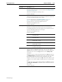
set igmp filter
Syntax
SET IGMP FILter=filter-id ENTry=1..65535
[GROupaddress=ipadd[-ipadd]] [ACtion={INCLude|EXCLude}]
where:
Description
■
filter-id is a decimal number in the range 1 to 99.
■
ipadd is an IP address in dotted decimal notation.
This command modifies an entry in an IGMP filter. IGMP filters control a
port’s membership of multicast groups by filtering Membership Reports
received from hosts attached to the port.
The filter parameter specifies the number of the filter that the entry belongs to.
A filter with the specified number must already exist.
The entry parameter specifies the entry to modify. An entry with the specified
number must already exist.
The groupaddress parameter specifies an IP multicast group address, or a
range of IP multicast group addresses to match. The IP addresses must be
multicast addresses.
The action parameter specifies the action to take when an IGMP Membership
Report group address matches the value of groupaddress. If you specify
include, Membership Reports matching groupaddress are processed as normal
by IGMP. If you specify exclude, Membership Reports matching groupaddress
are excluding from processing by IGMP, and the packets are discarded. The
default is include.
Software Version 2.7.5
C613-10454-00 REV A
Software Version 2.7.5
35
If an IGMP filter contains at least one entry, then Membership Reports for
group addresses that do not match any entries in the filter are implicitly
excluded and the packets are discarded.
Examples
To change the group address for entry 12 in filter 6 to the range 229.1.1.2 to
230.1.2.3, use the command:
set igmp fil=6 ent=12 gro=229.1.1.2-230.1.2.3
To change entry 1 in filter 2 to accept Membership Reports for multicast group
addresses matching the entry’s group address range, use the command:
set igmp fil=2 ent=1 ac=incl
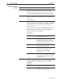
set igmpsnooping fastleave
Syntax
SET IGMPSNooping Fastleave={ON|OFF|YES|NO|True|False}
[INTerface=interface]
where interface is an interface name formed by concatenating a Layer 2
interface type (‘vlan’) and an interface instance.
Description
This command enables or disables Fast Leave processing for IGMP Snooping.
Fast Leave should not be configured on a port that has multiple hosts attached
because it may adversely affect multicast services to some hosts.
The fastleave parameter specifies whether Fast Leave processing is enabled or
disabled. If you specify on, yes or true then Fast Leave processing is enabled on
the specified VLAN or all VLANs. If you specify off, no or false then Fast
Leave processing is disabled on the specified VLAN or all VLANs. The default
is off.
The interface parameter specifies the VLAN on which Fast Leave processing is
to be enabled or disabled. If you do not specify an interface then the setting
applies to all VLANs.
Examples
To enable IGMP Snooping Fast Leave processing on VLAN ‘vlan2’, use the
command:
set igmpsn f=on int=vlan2
To enable IGMP Snooping Fast Leave processing on all VLANs, use the
command:
set igmpsn f=on
Software Version 2.7.5
C613-10454-00 REV A
36
IGMP Enhancements
Release Note
set switch port
Syntax
(AR400, AR700)
SET SWItch POrt={port-list|ALL} [BCLimit={NONE|limit}]
[DESCription=description] [DLFLimit={NONE|limit}]
[IGMPACtion={DENY|REPlace}]
[IGMPFIlter={NONE|filter-id}]
[IGMPMAxgroup={NONE|1..65535}] [INFILTering=OFF|ON]
[MCLimit={NONE|limit}] [POLarity={MDI|MDIX}]
[SPeed={AUTOnegotiate|10MHALf|10MFUll|10MHAUto|10MFAuto
|100MHALf|100MFUll|100MHAuto|100MFAuto|1000MFull|1000MF
Auto}]
Syntax
(Rapier, AT-8600,
AT-8700XL, AT-8800)
SET SWItch POrt={port-list|ALL} [ACCeptable={ALL|VLAN}]
[BCLimit={NONE|limit}] [DESCription=description]
[DLFLimit={NONE|limit}]
[EGResslimit={NONE|DEFault|0|1000..127000|8..1016}]
[IGMPACtion={DENY|REPlace}]
[IGMPFIlter={NONE|filter-id}]
[IGMPMAxgroup={NONE|1..65535}] [INFILTering={OFF|ON}]
[INGresslimit={NONE|DEFAULT|0|64..127000|8..1016}]
[LEARn={NONE|0|1..256]
[INTRusionaction={DISable|DIScard|TRap}]
[MCLimit={NONE|limit}] [MIRRor={BOTH|NONE|RX|TX}]
[MODe={AUTOnegotiate|MASTer|SLAve}]
[MULTicastmode={A|B|C}]
[SPeed={AUTOnegotiate|10MHALF|10MFULL|10MHAUTO|10MFAUTO
|100MHALF|100MFULL|100MHAUTO|100MFAUTO|1000MHALF|1000MF
ULL|1000MHAUTO|1000MFAUTO}]
Syntax
(AT-8900, AT-9900)
SET SWItch POrt={port-list|ALL} [ACCeptable={ALL|VLAN}]
[BCLimit={NONE|limit] [DESCription=description]
[EGResslimit={bandwidth|DEFault}]
[IGMPACtion={DENY|REPlace}]
[IGMPFIlter={NONE|filter-id}]
[IGMPMAxgroup={NONE|1..65535}] [INFILTering={OFF|ON}]
[INTRusionaction={DISable|DIScard|TRap}]
[LEARn={NONE|0|1..256] [MIRRor={BOTH|NONE|RX|TX}]
[MODe={AUTOnegotiate|MASTer|SLAve}]
[POLarity={MDI|MDIX}] [RELearn={OFF|ON}]
[SPeed={AUTOnegotiate|10MHALf|10MFUll|10MHAUto|10MFAuto
|100MHALf|100MFUll|100MHAUto|100MFAuto|1000MFUll|1000MF
AUto}] [THRASHLimit={NONE|1..65536}]
[THRASHRefill=1..65536]
Software Version 2.7.5
C613-10454-00 REV A
Software Version 2.7.5
Syntax
(AT-9800)
37
SET SWItch POrt={port-list|ALL} [ACCeptable={ALL|VLAN}]
[DESCription=description]
[EGResslimit={bandwidth|DEFault}] [FClength=length]
[IGMPACtion={DENY|REPlace}]
[IGMPFIlter={NONE|filter-id}]
[IGMPMAxgroup={NONE|1..65535}]
[INTRusionaction={DISable|DIScard|TRap}]
[JUmbo={ON|OFF|packetsize] [LEARn={NONE|0|1..256]
[MIRRor={BOTH|NONE|RX|TX}]
[MODe={AUTOnegotiate|MASTer|SLAve}] [RELearn={OFF|ON}]
[SPeed={AUTOnegotiate|10MHALf|10MFUll|10MHAUto|10MFAuto
|100MHALf|100MFUll|100MHAUto|100MFAuto|1000MHALf|1000MF
Ull|1000MHAUto|1000MFAUto}]
where:
Description
■
port-list is a port number, range (specified as n-m), or comma-separated list
of numbers and/or ranges. Port numbers start at 1 and end at m, where m
is the highest numbered switch port, including uplink ports.
■
limit is a decimal number, from 0 to the maximum value of the limit
variable based on the particular switch hardware.
■
description is a string 1 to 47 characters long. Valid characters are any
printable characters.
■
bandwidth is the maximum bandwidth available to the port in kbps,
specified in multiples of 64 kbps.
■
length is a physical length measured in metres.
■
packetsize is a single decimal number.
■
port-list is a port number, range (specified as n-m), or comma-separated list
of numbers and/or ranges. Port numbers start at 1 and end at m, where m
is the highest numbered switch port. Ports are identified either by a port
number or a card.port number. See Port Numbering in the Switching
chapter of the Software Reference for more information.
This command modifies the value of parameters for switch ports.
The new igmpaction parameter specifies the action to take when the number of
multicast group memberships associated with the port reaches the limit set by
igmpmaxgroup. If you specify deny, then additional Membership Reports are
discarded until existing group memberships age out. If you specify replace,
then additional membership entries will replace existing membership entries.
The default is deny.
The new igmpfilter parameter specifies the number of an IGMP filter to apply
to the port. An IGMP filter controls the multicast groups that the port can be a
member of by filtering IGMP Membership Reports from hosts attached to the
port. If you specify a filter number, an IGMP filter with the specified number
must already exist. You can apply an IGMP filter to more than one switch port,
but a single port can have only one filter assigned to it. Specify none to apply
no filter to the port, or to remove an existing filter from the port. The default is
none.
The new igmpmaxgroup parameter specifies the maximum number of
multicast groups that the port can join. Specify none to set no limit. The default
is none.
For trunk ports, the value of igmpaction, igmpfilter, and igmpmaxgroup for
the master port will apply to the trunk.
Software Version 2.7.5
C613-10454-00 REV A
38
IGMP Enhancements
Example
Release Note
To apply IGMP filter 1 to port 12, use the command:
set swi po=12 igmpfi=1
To limit the number of multicast groups that ports 12–23 can join to 50, use the
command:
set swi po=12-23 igmpma=50
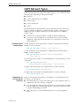
show igmp filter
Syntax
SHow IGMP FILter[=filter-id]
where:
■
Description
filter-id is a decimal number in the range 1 to 99.
This command displays information about an IGMP filter or all IGMP filters
(Figure 9, Table 12). If a filter is specified, only information about that filter is
displayed.
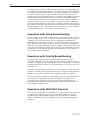
Figure 9: Example output from the show igmpfilter command
IGMP Filters
-----------------------------------------------------------------No. Entry Group Address
Action
Matches
-----------------------------------------------------------------1
Received: 230
Passed: 200
Dropped: 30
-----------------------------------------------------------------99
224
224.1.2.3
224.1.2.3
Exclude
10
229
229.1.1.1
229.2.2.2
Include
8
Received: 80
Passed: 70
Dropped: 10
------------------------------------------------------------------
Table 12: Parameters in the output of the show igmp filter command
Examples
Parameter
Meaning
No.
The filter number.
Entry
The entry number of an entry in this filter.
Group Address
The multicast group address range for this entry.
Action
The action to take when the group address of an IGMP
Membership Report matches this entry’s group address.
Matches
The number of IGMP Membership Reports matched by this entry.
Received
The number of IGMP Membership Reports received on the switch
port that this filter is attached to.
Passed
The number of IGMP Membership Reports included and
forwarded to IGMP for processing by this filter.
Dropped
The number of IGMP Membership Reports excluded and
discarded by this filter.
To display information about IGMP filter 3, use the command:
sh igmp fil=3
Software Version 2.7.5
C613-10454-00 REV A
Software Version 2.7.5
39
show igmpsnooping
Syntax
SHow IGMPSNooping [VLAN={vlan-name|1..4094}]
where vlan-name is a unique name for the VLAN 1 to 32 characters long. Valid
characters are uppercase and lowercase letters, digits, the underscore, and the
hyphen.
Description
The output of this command includes a new field (Figure 10, Table 13).
Figure 10: Example output from the show igmpsnooping command
IGMP Snooping
-------------------------------------------------------------------------------Status ........................... Enabled
Disabled All-groups ports ........ (list)
Vlan Name (vlan id) ..... default (1)
Fast Leave .............. On
Group List ..............
Group. 225.1.2.3
Ports 16,19
Entry timeout 268 secs
Group. 239.1.2.3
Ports 21
Entry timeout 180 secs
Vlan Name (vlan id) ..... vlan2 (2)
Fast Leave .............. On
Group List ..............
All Groups
Ports 13
Entry timeout 255 secs
Vlan Name (vlan id) ..... vlan3 (3)
Fast Leave .............. Off
Group List ..............
No group memberships.
--------------------------------------------------------------------------------
Table 13: New parameter in output of the show igmpsnooping command
Software Version 2.7.5
C613-10454-00 REV A
Parameter
Meaning
Fast Leave
Whether Fast Leave processing is enabled on this VLAN.
40
IGMP Enhancements
Release Note
show switch port
Syntax
SHow SWItch POrt[={port-list|ALL}]
where port-list is a port number, range (specified as n-m), or comma-separated
list of numbers and/or ranges. Port numbers start at 1 and end at m, where m is
the highest numbered Ethernet port.
Description
The output of this command includes a new field (Figure 11, Table 14).
The output shown is for AR400 and AR700 routers.
Figure 11: Example output from the show switch port command
Switch Port Information
----------------------------------------------------------Port ............................. 1
Description .................... To intranet hub, port 4
Status ......................... ENABLED
Link State ..................... Up
UpTime ......................... 00:10:49
Configured speed/duplex ........ Autonegotiate
Actual speed/duplex ............ 100 Mbps, full duplex
Automatic MDI/MDI-X ............ Enabled
Configured MDI/MDI-X............ MDI-X
Actual MDI/MDI-X................ MDI
Broadcast rate limit ........... 128Kbps
Multicast rate limit ........... DLF rate limit ................. Flow control ................... Disabled
Send tagged pkts for VLAN(s) ... vlan2 (2)
vlan3 (3)
Port-based VLAN ................ accounting (4)
Ingress Filtering .............. OFF
IGMP Filter .................... None
Max-groups/Joined .............. Undefined/0
IGMP Max-groups Action ......... Deny
----------------------------------------------------------
Table 14: New parameters in the output of the show switch port command
Parameter
Meaning
IGMP Filter
The IGMP filter applied to the port, or “None” if an IGMP
filter has not been set.
Max-groups/Joined
The maximum number of multicast groups the port can
join, or “Undefined” if a limit has not been set, and the
number of multicast groups that the port is currently a
member of.
IGMP Max-groups Action
The action to take when the port attempts to join more
multicast groups than the maximum allowed; one of
“Deny” or “Replace”.
Software Version 2.7.5
C613-10454-00 REV A
Software Version 2.7.5
41
OSPF Network Types
OSPF treats the networks attached to OSPF interfaces as one of the following
network types, depending on the physical media:
■
broadcast
■
non-broadcast multi-access (NBMA)
■
point-to-point
■
point-to-multipoint
■
virtual
By default, Ethernet and VLAN networks are treated as broadcast networks.
You can configure an Ethernet or VLAN interface as either a broadcast or an
NBMA network. Configure an Ethernet or VLAN interface as an NBMA
interface when:
Configuring the
network type
■
some devices on the network do not support multicast addressing
■
you want to select which devices on the network are to become OSPF
neighbours, rather than allow all the devices on the network to become
OSPF neighbours
To add an Ethernet or VLAN interface to OSPF as a broadcast network (the
default), use the command:
add ospf interface=interface [other-options...]
To add an Ethernet or VLAN interface to OSPF and set the network type to
NBMA, use the command:
add ospf interface=interface network=non-broadcast
[other-options...]
To change the network type of an existing Ethernet or VLAN interface, use the
command:
set ospf interface=interface
network={broadcast|non-broadcast} [other-options...]
To display the network type of an OSPF interface, use the command:
show ospf interface=interface full
To display the network types of all OSPF interfaces, use the command:
show ospf interface full
Neighbours on
non-broadcast
networks
Software Version 2.7.5
C613-10454-00 REV A
When you change the network type of an Ethernet or VLAN interface from
broadcast to non-broadcast:
■
All OSPF packets are sent as unicast messages, not broadcast messages, so
neighbours need to be statically configured.
■
Any existing dynamically learned neighbours are automatically converted
to static neighbours, and will appear in any configuration script created by
using the create config command.
■
Hello messages are not transmitted until at least one static neighbour
exists.
42
OSPF Network Types
Release Note
You can add, delete or modify static neighbours by using the commands:
add ospf neighbour=ipadd priority=0..255
delete ospf neighbour=ipadd
set ospf neighbour=ipadd
You can display the list of currently configured static neighbours using the
command:
show ospf neighbour
You can configure the time interval between hello messages sent to neighbours
that are deemed to be inactive. To do this, use the pollinterval parameter on
the add ospf interface and set ospf interface commands.
Neighbours on
broadcast networks
When you change the network type of an Ethernet or VLAN interface from
non-broadcast to broadcast:
■
Any existing statically defined neighbours are cleared.
■
Hello messages are sent as broadcast messages, so neighbours are
dynamically learned.
You can display the list of current neighbours using the command:
show ospf neighbour
Command Changes
The following table summarises the new and modified commands (see
Command Reference Updates).
Command
Change
add ospf interface
New network parameter
set ospf interface
New network parameter
show ospf interface
Existing Type field displays the current setting of the new
network parameter
Software Version 2.7.5
C613-10454-00 REV A
Software Version 2.7.5
43
Command Reference Updates
This section describes each new command and the changed portions of
modified commands and output screens. For modified commands and output,
new parameters, options and fields are shown in bold.
add ospf interface
Syntax
Description
Software Version 2.7.5
C613-10454-00 REV A
ADD OSPF INTerface=interface AREa={BAckbone|area-number}
[AUthentication={AREadefault|NONE|PASSword|MD5}]
[BOOST1=0..1023] [DEadinterval=2..2147483647]
[DEMand={ON|OFF|YES|NO|True|False}]
[HEllointerval=1..65535]
[NETwork={BROadcast|NON-broadcast}]
[PASSIve={ON|OFF|YES|NO|True|False}]
[PASSword=password] [POLLInterval=1..2147483647]
[PRIOrity=0..255] [RXmtinterval=1..3600]
[TRansitdelay=1..3600] [VIrtuallink=router-id]
The new network parameter specifies the OSPF network type of the interface,
and is only valid for Ethernet or VLAN interfaces. Specify broadcast if you
want OSPF to treat the network as a broadcast network. Hello messages are
transmitted as broadcast messages, and neighbours are learned dynamically.
You can not configure static neighbours or use the pollinterval parameter to set
the time interval between hello messages to inactive neighbours. Specify
non-broadcast if you want OSPF to treat the network as an NBMA network.
All OSPF packets are transmitted as unicast messages, so neighbours must be
statically defined. You can use the pollinterval parameter to set the time
interval between hello messages to inactive neighbours. The default is
broadcast.
44
OSPF Network Types
Release Note
set ospf interface
Syntax
SET OSPF INTerface=interface [AREa={BAckbone|area-number}]
[AUthentication={AREadefault|NONE|PASSword|MD5}]
[BOOST1=0..1023] [DEadinterval=2..2147483647]
[DEMand={ON|OFF|YES|NO|True|False}]
[HEllointerval=1..65535]
[NETwork={BROadcast|NON-broadcast}]
[PASSIve={ON|OFF|YES|NO|True|False}]
[PASSword=password] [POLLInterval=1..2147483647]
[PRIOrity=0..255] [RXminterval=1..3600]
[TRansitdelay=1..3600] [VIrtuallink=router-id]
Description
The new network parameter specifies the OSPF network type of the interface,
and is only valid for Ethernet or VLAN interfaces. Specify broadcast if you
want OSPF to treat the network as a broadcast network. Hello messages are
transmitted as broadcast messages, and neighbours are learned dynamically.
You can not configure static neighbours or use the pollinterval parameter to set
the time interval between hello messages to inactive neighbours. Specify
non-broadcast if you want OSPF to treat the network as an NBMA network.
All OSPF packets are transmitted as unicast messages, so neighbours must be
statically defined. You can use the pollinterval parameter to set the time
interval between hello messages to inactive neighbours. The default is
broadcast.
When you change the network type of an Ethernet or VLAN interface from
broadcast to non-broadcast:
■
All OSPF packets are sent as unicast messages, not broadcast messages, so
neighbours need to be statically configured.
■
Any existing dynamically learned neighbours are automatically converted
to static neighbours.
■
Hello messages are not transmitted until at least one static neighbour
exists.
When you change the network type of an Ethernet or VLAN interface from
non-broadcast to broadcast:
■
Any existing statically defined neighbours are cleared.
■
Hello messages are sent as broadcast messages, so neighbours are
dynamically learned.
Software Version 2.7.5
C613-10454-00 REV A
Software Version 2.7.5
45
show ospf interface
Syntax
Description
SHow OSPF INTerface[=interface]
[AREa={BAckbone|area-number}] [IPaddress=ipadd]
[{FULl|SUMmary}]
This command displays information about OSPF interfaces. The existing Type
field displays the configured network type.
Figure 12: Example output from show ospf interface command for a specified interface
vlan1:
Status ........................
Area ..........................
IP address ....................
IP net mask ...................
IP network number .............
Type ..........................
OSPF on demand ................
Passive .......................
State .........................
Router priority ...............
Transit delay .................
Retransmit interval ...........
Hello interval ................
Router dead interval ..........
Poll interval .................
Interface events ..............
Authentication ................
Password ......................
Designated router .............
Backup designated router ......
Metric boost 1 ................
Enabled
Backbone
192.168.250.1
255.255.255.0
192.168.250.0
broadcast
ON (OFF)
No
otherDR
5
1 second
5 seconds
10 seconds
40 seconds
120 seconds
1
Password (area default)
Charlie1
192.168.250.254
192.168.250.253
0
Table 15: Changed parameter in the output of the show ospf interface command for a
specific interface
Parameter
Meaning
Type
Type of network associated with the interface:
Broadcast
NBMA (non-broadcast multi-access)
Point-to-Point
Unknown
Virtual
Software Version 2.7.5
C613-10454-00 REV A
46
BGP Enhancements
Release Note
BGP Enhancements
Software Version 2.7.5 includes the following enhancements for BGP:
■
Changes to Algorithm for Determining the Best Route
■
Automatic Summarising: Advertising as Few Routes as Possible
■
Importing and Advertising the Default Route
This section describes each enhancement, then the new and modified
commands in Command Reference Updates.
Changes to Algorithm for Determining the Best Route
When multiple routes to a destination exist, BGP now uses the rules in the
following table to determine which route is the best one. If a rule results in
selection of a single route, the router or switch uses that route. If multiple
routes still match, the router or switch goes to the next rule.
Rule For this...
the router or switch chooses the route that...
1
has the highest local preference. How the router or
switch determines the local preference depends on the
source of the route:
local_preference
• For routes that the router or switch learned via an
EBGP session, or for routes it learned from sources
such as an IGP or static configuration, the router or
switch calculates the value of the preference itself.
• For routes that the router or switch learned from an
IBGP peer, the router or switch uses the preference
supplied by the peer—the update message for that
route contains a local_preference attribute indicating
the degree of preference.
2
route type
came into the BGP routing table from a preferred source.
The order of preference is:
a. routes imported into the BGP routing table from the
router or switch’s RIB, using BGP import or network
entries
b. routes learned from an IBGP or confederation peer
c. routes learned from an EBGP peer
d. routes learned through a BGP aggregate entry
3
AS_path
has the shortest AS path.
4
origin
has the preferred origin. The order of preference is:
a. IGP
b. EGP
c. INCOMPLETE
5
Multi_Exit_Discriminator
value
has the lowest MED value. This rule applies if the local
system is configured to take into account the value of the
Multi_Exit_Discriminator (MED), and if the multiple
routes are learned from the same neighbouring AS.
Software Version 2.7.5
C613-10454-00 REV A
Software Version 2.7.5
47
Rule For this...
the router or switch chooses the route that...
6
has external AS numbers in its AS path, rather than a
route that has AS confederation sets or sequences in its
AS path. Routes with external AS numbers are
considered external paths; routes with AS confederation
sets or sequences are internal paths.
path type
Note that candidate routes’ AS paths only contain EBGP
and confederation AS numbers, because BGP drops
routes with the local AS path in their path list.
7
next_hop attribute
has the minimum cost to the next hop specified in the
next_hop attribute. Deciding the cost involves looking
into the IP route table.
8
router ID
it learned from the peer with the lowest router ID. The
peer’s router ID is determined by the following rules:
• If the peer has been configured with a router ID by
using the command set bgp routerid=ipadd, that
address is used as its router ID.
• Otherwise, if a local IP address has been set for the
peer, that address is used as its router ID.
• Otherwise, if neither has been set, the highest IP
address configured on any of the peer’s interfaces is
used as its router ID.
9
cluster list
has the shortest cluster list. The cluster list attribute only
exists within Autonomous Systems that use route
reflection, so if the router or switch’s AS does not use
route reflection, the cluster list is treated as having a
length of zero.
10
neighbour address
it learned from the peer with the lowest neighbour IP
address. The neighbour IP address is the address that the
peer uses for the TCP connection that supports the peer
session. For more information about the address routers
or switches use, see How to Set the IP Address that
Identifies the Switch in the BGP chapter of the Software
Reference.
Command Changes
There are no command changes for this enhancement.
Software Version 2.7.5
C613-10454-00 REV A
48
BGP Enhancements
Release Note
Automatic Summarising: Advertising as Few Routes
as Possible
Problem
Solution
When BGP learns routes, it imports and advertises every route, even if some
are routes to subnets of the same network. For example, if you used the subnets
192.168.1.64/26 and 192.168.1.128/26, BGP would advertise routes to both of
these. Depending on the router or switch’s role in your network, this may be
undesirable because it:
■
exposes network topology
■
creates more update messages than necessary
■
increases the size of the routing table
With Software Version 2.7.5, there are two available solutions:
■
The new automatic summarising feature, which enables BGP to
automatically summarise all locally-originated prefixes into their class A, B
or C networks. This option allows BGP to summarise prefixes when it
imports OSPF, RIP, interface and statically-configured routes.
Automatic Summarising describes this new feature.
■
The existing route aggregation feature, which is useful when you want to
summarise subnet routes that are within particular class A, B or C
networks. This option allows BGP to summarise subnets from any source,
including from BGP peers.
Route aggregation is an existing feature, but we have improved the
Software Reference’s description of it. Aggregating Routes contains the
new description.
Automatic Summarising
About automatic
summarising
When BGP imports routes from another routing source, such as OSPF, by
default it stores and advertises every route, no matter how specific. If your
LAN is divided into subnets, this means BGP advertises a route to each subnet.
You can avoid this by enabling automatic summarising. This feature
summarises prefixes into networks and only advertises a route to that network.
It is particularly useful on the external speaker for an AS—the router or switch
that links an internal network to a public network.
When you enable automatic summarising, the router or switch summarises
subnets into their Class A, B or C network. Instead of writing the route to the
subnet into the BGP routing table and advertising that subnet route, it writes a
single route to the summary network. For example, instead of storing and
advertising routes to 192.168.1.64/26 and 192.168.1.128/26, BGP would have
one route to 192.168.1.0/24.
Caution Only turn on automatic summarising if you own the whole classful
network for your locally-generated routes. Otherwise, you advertise yourself as
the next hop for subnets that you do not own.
For example, if you owned 202.202.202.0/24, you could use automatic
summarising. However, if you only owned 202.202.202.64/26, you must not use
automatic summarising.
Software Version 2.7.5
C613-10454-00 REV A
Software Version 2.7.5
Configuring
automatic
summarising
49
If you want to import routes from RIB into BGP and automatically summarise
them into networks, use the following procedure. Instead of importing routes
to subnets within each network, BGP then imports and advertises the route to
the summary network. It specifies this router or switch as the next hop for the
summary route.
Step Command
add bgp import={interface|ospf|rip|static}
[routemap=routemap]
Turn on importing for the required
routing source or network.
or
add bgp network=prefix[/0..32]
[mask=mask] [routemap=routemap]
Note that automatic summarising
applies to all routes that BGP imports. If
you configure multiple import or
network entries, BGP summarises routes
from all of them.
2
enable bgp autosummary
Enable automatic summarising.
3
show bgp route
Check that BGP has imported and
summarised the desired networks.
1
Examples of
automatic
summarising
Action
The following table uses the example of the static routes 192.168.1.64/26 and
192.168.1.128/26 to show what BGP advertises with different combinations of
import and network entries, with and without automatic summarising.
Automatic summarising?
Commands
BGP advertises
No
add bgp import=static
Routes to 192.168.1.64/26 and
192.168.1.128/26.
add ip route=192.168.1.64/26 nexthop=ipadd
add ip route=192.168.1.128/26 nexthop=ipadd
add bgp network=192.168.1.0/24
add ip route=192.168.1.64/26 nexthop=ipadd
add ip route=192.168.1.128/26 nexthop=ipadd
add bgp import=static
add bgp network=192.168.1.0/24
add ip route=192.168.1.64/26 nexthop=ipadd
add ip route=192.168.1.128/26 nexthop=ipadd
Yes
add bgp import=static
enable bgp autosummary
add ip route=192.168.1.64/26 nexthop=ipadd
add ip route=192.168.1.128/26 nexthop=ipadd
add bgp network=192.168.1.0/24
enable bgp autosummary
add ip route=192.168.1.64/26 nexthop=ipadd
add ip route=192.168.1.128/26 nexthop=ipadd
add bgp import=static
add bgp network=192.168.1.0/24
enable bgp autosummary
add ip route=192.168.1.64/26 nexthop=ipadd
add ip route=192.168.1.128/26 nexthop=ipadd
Software Version 2.7.5
C613-10454-00 REV A
Nothing. BGP does not advertise a route
to 192.168.1.0/24 unless it can find one
in the router or switch’s RIB.
Routes to 192.168.1.64/26 and
192.168.1.128/26. BGP does not
advertise a route to 192.168.1.0/24
unless it can find one in the router or
switch’s RIB.
A single route to 192.168.1.0/24 with
nexthop=0.0.0.0. Automatic
summarising replaces the two subnet
entries in the BGP routing table with this
one entry.
A single route to 192.168.1.0/24 with
nexthop=0.0.0.0. BGP advertises
192.168.1.0/24 because it finds a route
to that network in the router or switch’s
RIB.
A single route to 192.168.1.0/24 with
nexthop=0.0.0.0. You do not need to
specify both import and network
entries.
50
BGP Enhancements
Release Note
Aggregating Routes
About route
aggregation
When BGP receives routes from its peers or imports them from the RIB, by
default it advertises every route, no matter how specific. You can reduce the
number of routes BGP advertises, by configuring aggregate prefix entries. If the
router or switch receives a route to a subset of the entry’s prefix, BGP adds the
aggregate prefix to its database, as well as the route for the more specific prefix.
You can set the router or switch to advertise only the aggregate.
Consider a configuration in which you create an aggregate entry of
192.168.1.0/24 and set the aggregate entry to advertise only the aggregate. If
the router or switch receives routes to the prefixes 192.168.1.64/26 and
192.168.1.128/26, it stores all three prefixes but only advertises 192.168.1.0/24.
Note that the router or switch does not use the aggregate route for IP routing.
The router or switch only uses the aggregate to determine which routes to
advertise.
The router or switch advertises the aggregate route as coming from the router
or switch’s autonomous system, and sets the aggregate’s atomic_aggregate
attribute.
Caution Make sure that you own all the IP addresses in the aggregate entry.
Otherwise, you advertise yourself as the next hop to addresses that you do not
own.
For example, if you own 202.202.202.0/24, you can configure that as an
aggregate entry. However, if you only own 202.202.202.64/26, you must not
configure an aggregate of 202.202.202.0/24.
Configuring route
aggregation
To aggregate subnets and only advertise the aggregate prefix, use the
command:
add bgp aggregate=prefix[/0..32] [mask=mask] summary=yes
[routemap=routemap]
The aggregate parameter specifies the network that BGP aggregates subnets
into.
The summary parameter controls advertisement. If this parameter is yes, the
router or switch only advertises the route to the aggregate. Note that
unadvertised routes are still displayed in output of the show bgp route
command, but are marked with an “s”.
Creating an aggregate entry does not immediately add the aggregate prefix to
the BGP routing table. BGP adds the aggregate prefix when it receives an
advertisement of a more specific subnet.
Command Changes
The following table summarises the new and modified commands for
automatic summarising (see Command Reference Updates).
Command
Change
enable bgp autosummary
New command
disable bgp autosummary
New command
show bgp
New Auto summary field
Software Version 2.7.5
C613-10454-00 REV A
Software Version 2.7.5
51
Importing and Advertising the Default Route
Software Version 2.7.5 enables you to control whether:
■
BGP imports the default route (0.0.0.0/0) from the router or switch RIB into
the BGP routing table
To configure this feature, use the new commands:
enable bgp defaultoriginate
disable bgp defaultoriginate
■
BGP advertises the default route to its peers
To configure this feature, use the new defaultoriginate parameter in the
commands:
add bgp peer
set bgp peer
Command Changes
The following table summarises the new and modified commands (see
Command Reference Updates).
Command
Change
Importing the default route into BGP
enable bgp defaultoriginate
New command
disable bgp defaultoriginate
New command
show bgp
New Default route origination field
Advertising the default route to a BGP peer
Software Version 2.7.5
C613-10454-00 REV A
add bgp peer
New defaultoriginate parameter
set bgp peer
New defaultoriginate parameter
show bgp peer
New Default originate field
52
BGP Enhancements
Release Note
Command Reference Updates
This section describes each new command and the changed portions of
modified commands and output screens. For modified commands and output,
new parameters, options and fields are shown in bold.
add bgp peer
Syntax
Description
ADD BGP PEer=ipadd REMoteas=1 ..65534
[DEFaultoriginate={NO|YES}] [other-options...]
The new defaultoriginate parameter specifies whether to advertise the default
route (0.0.0.0/0) to this peer, when the router or switch’s BGP routing table
contains the default route. To advertise the default route, you need to do all of
the following:
■
set this parameter to yes
■
create the default route on the router or switch (or the router or switch
needs to learn it from another routing source)
■
configure BGP with an import or network entry that includes the default
route
■
import the default route into the BGP routing table, by using the enable
bgp defaultoriginate command on page 54
The default is no. Therefore, by default the router or switch does not propagate
the default route from its BGP routing table to the peer's RIB.
disable bgp autosummary
Syntax
Description
DISable BGP AUTOSUmmary
This command stops the router or switch from automatically summarising
locally originated or imported subnet routes into a single route.
Automatic summary is disabled by default.
Example
To disable automatic summary, use the command:
dis bgp autosu
Software Version 2.7.5
C613-10454-00 REV A
Software Version 2.7.5
53
disable bgp defaultoriginate
Syntax
Description
DISable BGP DEFaultoriginate
This command prevents BGP from importing the default route (0.0.0.0/0) into
its routing table. This command over-rides other import options, so BGP does
not import the default route even when it is configured with an import or
network entry that includes the default route.
This feature is disabled by default. Therefore, by default BGP excludes the
default route.
Example
To prevent BGP from importing the default route, use the command:
dis bgp def
enable bgp autosummary
Syntax
Description
Example
ENAble BGP AUTOSUmmary
This command enables the router or switch to automatically summarise locally
originated or imported subnet routes. When automatic summarising is
enabled, the router or switch summarises routes that are under the same
classful network to a single route of the classful network. The router or switch
imports and advertises the summary route instead. Automatic summary is
disabled by default.
To enable automatic summary, use the command:
ena bgp autosu
Software Version 2.7.5
C613-10454-00 REV A
54
BGP Enhancements
Release Note
enable bgp defaultoriginate
Syntax
Description
ENAble BGP DEFaultoriginate
This command enables BGP to import the default route (0.0.0.0/0) into its
routing table. You also need to do both of the following:
■
create the default route on the router or switch (or the router or switch
needs to learn it from another routing source)
■
configure BGP with an import or network entry that includes the default
route
This feature is disabled by default. Therefore, by default BGP excludes the
default route.
To configure an import entry that includes the default route, use the add bgp
import command and specify the default route type in the import parameter
(most often import=static).
To configure a network entry that includes the default route, use the add bgp
network command and specify network=0.0.0.0/0.
This command does not determine whether the router or switch advertises the
default route to its BGP peers. You can configure that for each peer, by using
the defaultoriginate parameter of the add bgp peer command.
Note that you do not need to enable this feature if you want to aggregate
subnets of 0.0.0.0 into a single network route of 0.0.0.0/0. Instead, create an
aggregate entry of 0.0.0.0/0 by using the add bgp aggregate command.
Example
To enable BGP to import the default route, use the command:
ena bgp def
set bgp peer
Syntax
Description
SET BGP PEer=ipadd [DEFaultoriginate={NO|YES}]
[other-options...]
The new defaultoriginate parameter specifies whether to advertise the default
route (0.0.0.0/0) to this peer when the router or switch’s BGP routing table
contains the default route. To advertise the default route, you need to do all of
the following:
■
set this parameter to yes
■
create the default route on the router or switch (or the router or switch
needs to learn it from another routing source)
■
configure BGP with an import or network entry that includes the default
route
■
import the default route into the BGP routing table, by using the enable
bgp defaultoriginate command on page 54
The default is no. Therefore, by default the router or switch does not propagate
the default route from its BGP routing table to the peer's RIB.
Software Version 2.7.5
C613-10454-00 REV A
Software Version 2.7.5
55
show bgp
Syntax
Description
SHow BGP
The output of this command includes a new field.
Figure 13: Example output from the show bgp command
BGP router ID .................
BGP Cluster ID ................
Local autonomous system .......
Confederation ID ..............
Local preference ..............
Multi Exit Discriminator ......
Route table route map .........
Auto soft reconfiguration .....
Default route origination .....
Auto summary ..................
Number of peers
Defined .....................
Established .................
BGP route table
Iteration ...................
Number of routes ............
Route table memory ..........
192.168.1.1
192.168.1.1
123
1234
100 (default)
Disabled
Disabled
Disabled
4
2
231
12654
431872
BGP route flap damping ........ Enabled
Table 16: New parameters in the output of the show bgp command
Parameter
Meaning
Default route origination
Whether BGP imports the default route (0.0.0.0/0) into its
routing table, when both of the following conditions occur:
• the default route is present in the router or switch’s RIB
• BGP is configured with an import or network entry that
includes the default route.
Auto summary
Software Version 2.7.5
C613-10454-00 REV A
Whether the router or switch automatically summarises locally
originated or imported subnet routes into a classful network
route; one of Enabled or Disabled.
56
BGP Enhancements
Release Note
show bgp peer
Syntax
Description
SHow BGP PEer[=ipadd]
The output of this command includes a new field.
Figure 14: Example output from the show bgp peer command for a specific peer
Peer ................
Description .........
State ...............
Policy Template .....
Description .......
Private AS filter ...
Remote AS ...........
BGP Identifier ......
Authentication ......
Password ..........
Fast Fall-Over ......
Default originate ...
.
.
.
192.168.10.1
Idle
4
Test Template 1
Yes
3
172.20.25.2
None
ENABLED
DISABLED
Table 17: New parameter in the output of the show bgp peer command for a specific
peer
Parameter
Meaning
Default originate
Whether BGP advertises the default route (0.0.0.0/0) to this peer,
when the router or switch’s BGP routing table contains the default
route.
Software Version 2.7.5
C613-10454-00 REV A
Software Version 2.7.5
57
Classifying According to the Layer 5 Byte
Software Version 2.7.5 enables you to create classifiers that match specific bytes
in the Layer 5 part of IP packets. Layer 5 is the Layer 4 payload, so the new
classifier parameters match parts of the TCP or UDP payload. The switch can
perform its full array of hardware filtering and Quality of Service actions on
matched traffic.
The flexibility of this classifier option means you can match the traffic you need
to, even new protocols. You are not limited to pre-defined protocol options.
This enables you to isolate new network attacks and peer-to-peer applications
for network protection, monitoring and access control.
To create the classifier, use the new l5byte parameters in the create classifier or
set classifier commands.
Command Changes
The following table summarises the modified commands (see Command
Reference Updates).
Command
Change
create classifier
16 new l5byte parameters
set classifier
16 new l5byte parameters
show classifier
16 new l5byte parameters
New Layer 5 Byte fields
Software Version 2.7.5
C613-10454-00 REV A
58
Classifying According to the Layer 5 Byte
Release Note
Command Reference Updates
This section describes each new command and the changed portions of
modified commands and output screens. For modified commands and output,
new parameters, options and fields are shown in bold.
create classifier
Syntax
CREate CLASSifier=rule-id
[MACSaddr={macadd|ANY}] [MACDaddr={macadd|ANY}]
[MACType={L2Ucast|L2Mcast|L2Bcast|ANY}] [TPID=tpid|ANY]
[VLANPriority=0..7|ANY] [VLAN={vlanname|1..4094|ANY}]
[INNERTpid=tpid|ANY] [INNERVLANPriority=0..7|ANY]
[INNERVLANId=VLAN=1..4094|ANY]
[ETHFormat={802.2-Tagged|802.2-Untagged|ETHII-Tagged|
ETHII-Untagged|NETWARERAW-Tagged|Netwareraw-untagged|
SNAP-Tagged|SNAP-Untagged|ANY}]
[PROTocol={protocoltype|IP|IPX|ANY}]
[IPDScp={dscplist|ANY}] [IPTOs={0..7|ANY}]
[IPSAddr={ipaddmask|ANY}] [IPDAddr={ipaddmask|ANY}]
[IPPRotocol={TCP|UDP|ICMp|IGMp|ipprotocolnum|ANY}]
[IPXDAddr={ipxadd|ANY}]
[IPXDSocket={NCP|SAP|RIP|NNB|DIAg|NLSp|IPXwan|
ipxsocketnum|ANY}]
[IPXSSocket={NCP|SAP|RIP|NNB|DIAg|NLSp|IPXwan|
ipxsocketnum|ANY}]
[TCPSport={portid|ANY}] [TCPDport={portid|ANY}]
[UDPSport={portid|ANY}] [UDPDport={portid|ANY}]
[L4SMask=mask|ANY] [L4DMask=mask|ANY]
[L5BYTE01=byteoffset,bytevalue[,bytemask]]
[L5BYTE02=byteoffset,bytevalue[,bytemask]]
[L5BYTE03=byteoffset,bytevalue[,bytemask]]
[L5BYTE04=byteoffset,bytevalue[,bytemask]]
[L5BYTE05=byteoffset,bytevalue[,bytemask]]
[L5BYTE06=byteoffset,bytevalue[,bytemask]]
[L5BYTE07=byteoffset,bytevalue[,bytemask]]
[L5BYTE08=byteoffset,bytevalue[,bytemask]]
[L5BYTE09=byteoffset,bytevalue[,bytemask]]
[L5BYTE10=byteoffset,bytevalue[,bytemask]]
[L5BYTE11=byteoffset,bytevalue[,bytemask]]
[L5BYTE12=byteoffset,bytevalue[,bytemask]]
[L5BYTE13=byteoffset,bytevalue[,bytemask]]
[L5BYTE14=byteoffset,bytevalue[,bytemask]]
[L5BYTE15=byteoffset,bytevalue[,bytemask]]
[L5BYTE16=byteoffset,bytevalue[,bytemask]]
Description
The new l5byte01 to l5byte16 parameters each specify the properties of a
single byte field to match in the Layer 5 part of IP packets, which is the TCP or
UDP payload. For each byte field you want to match, specify:
■
byteoffset, which is a decimal number in the range 0 to 37. This specifies the
location of the byte to match. It refers to the offset from the start of Layer 5,
after the UDP or TCP header
■
bytevalue, which is a 2-digit hexadecimal number. This specifies the value
of the byte at the position in the frame that is determined by byteoffset. The
classifier matches packets that have this value at this location
Software Version 2.7.5
C613-10454-00 REV A
Software Version 2.7.5
59
■
(optionally) bytemask, which is a 2-digit hexadecimal number. This specifies
an eight-bit binary mask to apply to the field. When a bit is set to 1 in the
mask, the value of the bit at the same position in the byte value is used to
determine a match. A 0 in the mask means that the corresponding bit is
ignored. The default is ff, which means the classifier matches against all
bits in the byte.
Caution The classifier matches only Layer 5 bytes that are within the first 80
bytes of the IP packet. The classifier does not match against bytes that are later
in the packet, even if they match the classifier’s settings.
When you consider packet length, remember that the location of Layer 5 in a
frame varies depending on the length of the lower-layer headers. This is because
header values such as the VLAN tag can be missing, and header values such as
the Ethernet format specification vary in length.
You must use l5byte01 as the first byte field and you must number additional
byte fields sequentially. Each field must have a greater offset than the fields
that precede it.
The l5byte parameters match frames with a valid TCP or UDP header, when
the network protocol is IP version 4. Therefore, protocol defaults to ip and does
not need to be specified. You also do not have to specify ipprotocol, but by
default the classifier applies to both TCP and UDP packets.
set classifier
Syntax
Software Version 2.7.5
C613-10454-00 REV A
SET CLASSifier=rule-id
[MACSaddr={macadd|ANY}] [MACDaddr={macadd|ANY}]
[MACType={L2Ucast|L2Mcast|L2Bcast|ANY}] [TPID=tpid|ANY]
[VLANPriority=0..7|ANY] [VLAN={vlanname|1..4094|ANY}]
[INNERTpid=tpid|ANY] [INNERVLANPriority=0..7|ANY]
[INNERVLANId=VLAN=1..4094|ANY]
[ETHFormat={802.2-Tagged|802.2-Untagged|ETHII-Tagged|
ETHII-Untagged|NETWARERAW-Tagged|Netwareraw-untagged|
SNAP-Tagged|SNAP-Untagged|ANY}]
[PROTocol={protocoltype|IP|IPX|ANY}]
[IPDScp={dscplist|ANY}] [IPTOs={0..7|ANY}]
[IPSAddr={ipaddmask|ANY}] [IPDAddr={ipaddmask|ANY}]
[IPPRotocol={TCP|UDP|ICMp|IGMp|ipprotocolnum|ANY}]
[IPXDAddr={ipxadd|ANY}]
[IPXDSocket={NCP|SAP|RIP|NNB|DIAg|NLSp|IPXwan|
ipxsocketnum|ANY}]
[IPXSSocket={NCP|SAP|RIP|NNB|DIAg|NLSp|IPXwan|
ipxsocketnum|ANY}]
[TCPSport={portid|ANY}] [TCPDport={portid|ANY}]
[UDPSport={portid|ANY}] [UDPDport={portid|ANY}]
[L4SMask=mask|ANY] [L4DMask=mask|ANY]
[L5BYTE01=byteoffset,bytevalue[,bytemask]]
[L5BYTE02=byteoffset,bytevalue[,bytemask]]
[L5BYTE03=byteoffset,bytevalue[,bytemask]]
[L5BYTE04=byteoffset,bytevalue[,bytemask]]
[L5BYTE05=byteoffset,bytevalue[,bytemask]]
[L5BYTE06=byteoffset,bytevalue[,bytemask]]
60
Classifying According to the Layer 5 Byte
Release Note
[L5BYTE07=byteoffset,bytevalue[,bytemask]]
[L5BYTE08=byteoffset,bytevalue[,bytemask]]
[L5BYTE09=byteoffset,bytevalue[,bytemask]]
[L5BYTE10=byteoffset,bytevalue[,bytemask]]
[L5BYTE11=byteoffset,bytevalue[,bytemask]]
[L5BYTE12=byteoffset,bytevalue[,bytemask]]
[L5BYTE13=byteoffset,bytevalue[,bytemask]]
[L5BYTE14=byteoffset,bytevalue[,bytemask]]
[L5BYTE15=byteoffset,bytevalue[,bytemask]]
[L5BYTE16=byteoffset,bytevalue[,bytemask]]
Description
The new l5byte01 to l5byte16 parameters each specify the properties of a
single byte field to match in the Layer 5 part of IP packets, which is the TCP or
UDP payload. For each byte field you want to match, specify:
■
byteoffset, which is a decimal number in the range 0 to 37. This specifies the
location of the byte to match. It refers to the offset from the start of Layer 5,
after the UDP or TCP header.
■
bytevalue, which is a 2-digit hexadecimal number. This specifies the value
of the byte at the position in the frame that is determined by byteoffset. The
classifier matches packets that have this value at this location
■
(optionally) bytemask, which is a 2-digit hexadecimal number. This specifies
an eight-bit binary mask to apply to the field. When a bit is set to 1 in the
mask, the value of the bit at the same position in the byte value is used to
determine a match. A 0 in the mask means that the corresponding bit is
ignored. The default is ff, which means the classifier matches against all
bits in the byte.
Caution The classifier matches only Layer 5 bytes that are within the first 80
bytes of the IP packet. The classifier does not match against bytes that are later
in the packet, even if they match the classifier’s settings.
When you consider packet length, remember that the location of Layer 5 in a
frame varies depending on the length of the lower-layer headers. This is because
header values such as the VLAN tag can be missing, and header values such as
the Ethernet format specification vary in length.
You must use l5byte01 as the first byte field and you must number additional
byte fields sequentially. Each field must have a greater offset than the fields
that precede it.
The l5byte parameters match frames with a valid TCP or UDP header, when
the network protocol is IP version 4. Therefore, protocol defaults to ip and does
not need to be specified. You also do not have to specify ipprotocol, but by
default the classifier applies to both TCP and UDP packets.
Software Version 2.7.5
C613-10454-00 REV A
Software Version 2.7.5
61
show classifier
Syntax
SHow CLASSifier[={rule-id|ALL}] [MACSaddr={macadd|ANY}]
[MACDaddr={macadd|ANY}]
[MACType={L2Ucast|L2Mcast|L2Bcast|ANY}] [TPID=tpid|ANY]
[VLANPriority=0..7|ANY] [VLAN={vlanname|1..4094|ANY}]
[INNERTpid=tpid|ANY] [INNERVLANPriority=0..7|ANY]
[INNERVLANId=VLAN=1..4094|ANY]
[ETHFormat={802.2-Tagged|802.2-Untagged|ETHII-Tagged|
ETHII-Untagged|NETWARERAW-Tagged|Netwareraw-untagged|
SNAP-Tagged|SNAP-Untagged|ANY}]
[PROTocol={protocoltype|IP|IPV6|IPX|ANY}]
[IPDScp={dscplist|ANY}] [IPTOs={0..7|ANY}]
[IPSAddr={ipaddmask|ipv6-add/prefix-length|ANY}]
[IPDAddr={ipaddmask|ipv6-add/prefix-length|ANY}]
[IPPRotocol={TCP|UDP|ICMp|IGMp|ipprotocolnum|ANY}]
[IPXDAddr={ipxadd|ANY}]
[IPXDSocket={NCP|SAP|RIP|NNB|DIAg|NLSp|IPXwan|
ipxsocketnum|ANY}]
[IPXSSocket={NCP|SAP|RIP|NNB|DIAg|NLSp|IPXwan|
ipxsocketnum|ANY}]
[TCPSport={portid|ANY}] [TCPDport={portid|ANY}]
[UDPSport={portid|ANY}] [UDPDport={portid|ANY}]
[L4SMask=mask|ANY] [L4DMask=mask|ANY]
[L5BYTE01=byteoffset,bytevalue[,bytemask]]
[L5BYTE02=byteoffset,bytevalue[,bytemask]]
[L5BYTE03=byteoffset,bytevalue[,bytemask]]
[L5BYTE04=byteoffset,bytevalue[,bytemask]]
[L5BYTE05=byteoffset,bytevalue[,bytemask]]
[L5BYTE06=byteoffset,bytevalue[,bytemask]]
[L5BYTE07=byteoffset,bytevalue[,bytemask]]
[L5BYTE08=byteoffset,bytevalue[,bytemask]]
[L5BYTE09=byteoffset,bytevalue[,bytemask]]
[L5BYTE10=byteoffset,bytevalue[,bytemask]]
[L5BYTE11=byteoffset,bytevalue[,bytemask]]
[L5BYTE12=byteoffset,bytevalue[,bytemask]]
[L5BYTE13=byteoffset,bytevalue[,bytemask]]
[L5BYTE14=byteoffset,bytevalue[,bytemask]]
[L5BYTE15=byteoffset,bytevalue[,bytemask]]
[L5BYTE16=byteoffset,bytevalue[,bytemask]]
Description
This command displays information about classifiers. If you specify any of the
new l5byte01 to l5byte16 parameters, the switch only displays classifiers that
match that parameter.
Software Version 2.7.5
C613-10454-00 REV A
62
Classifying According to the Layer 5 Byte
Release Note
Figure 15: Example output from the show classifier command (layer 5 byte data)
Classifier Rules
-----------------------------------------------------------Rule .................. 1
S-IP Address ......... ANY
D-IP Address ......... ANY
IP Protocol .......... ANY
TOS/DSCP ............. ANY
Layer 5 Byte 01:
Offset ............. 0
Value .............. 50
Layer 5 Byte 02:
Offset ............. 1
Value .............. 4f
Layer 5 Byte 03:
Offset ............. 2
Value .............. 53
Layer 5 Byte 04:
Offset ............. 3
Value .............. 54
Mask ............... fc
------------------------------------------------------------
Table 18: New parameters in the output of the show classifier command (layer 5 byte
data)
Parameter
Meaning
Layer 5 Byte 01 to
Layer 5 Byte 16
Each Layer 5 Byte field specifies the properties of a single byte field
to match in the Layer 5 part of IP packets, which is the TCP or UDP
payload.
Offset
The offset of a byte from the start of Layer 5. This specifies the
location of the byte to match.
Value
The hexadecimal value to match at the location specified by Offset
Mask
A hexadecimal number that specifies an eight-bit binary mask to
apply to the value before determining a match. A 1 in the mask
means that the value of the bit in that position is used to determine
a match, and a 0 means that the bit is ignored.
Software Version 2.7.5
C613-10454-00 REV A
Software Version 2.7.5
63
Firewall Enhancements
Software Version 2.7.5 includes the following enhancements to the firewall:
■
Increased Number of Firewall Policy Rules
■
SIP Application Layer Gateway Diagnostic Tools
■
UDP Port Timeout
This section describes each enhancement, then the new and modified
commands in Command Reference Updates.
Increased Number of Firewall Policy Rules
Software Version 2.7.5 enables you to associate up to 699 rules with each
interface in a firewall policy. To associate rules with a firewall policy, use the
existing command:
add firewall policy=policy-name rule=rule-id
action={allow|deny|nat|nonat} interface=interface
protocol={protocol|all|egp|gre|icmp|ospf|sa|tcp|udp}
[other-options...]
Command Changes
There are no command changes for this enhancement.
SIP Application Layer Gateway Diagnostic Tools
Debugging
With Software Version 2.7.5, the command syntax for specifying SIP
Application Layer Gateway (ALG) debugging has changed, and you can
debug traffic to and from particular IP addresses. To enable SIP ALG
debugging, use the command:
enable firewall policy[=policy-name] debug=sipalg
[debugmode={all|errorcode|message|parsing|trace}]
[ip=ipadd[-ipadd]]
To disable SIP ALG debugging, use the command:
disable firewall policy[=policy-name] debug=sipalg
[debugmode={all|errorcode|message|parsing|trace}]
[ip=ipadd[-ipadd]]
To see the debugging settings, use the command:
show firewall policy[=policy-name]
Logging
Software Version 2.7.5 enables the firewall to create SIP ALG log messages for a
wide variety of actions, ranging from normal operation to error conditions. To
collect log messages, first configure the logging module. Then enable the
firewall to create SIP ALG log messages, by using the command:
enable firewall policy[=policy-name] log=sipalg
[other-options...]
To disable SIP ALG logging, use the command:
disable firewall policy[=policy-name] log=sipalg
[other-options...]
Software Version 2.7.5
C613-10454-00 REV A
64
Firewall Enhancements
Release Note
To see the logging settings, use the command:
show firewall policy[=policy-name]
Displaying Sessions
Software Version 2.7.5 enables you to limit information displayed about
firewall sessions to only the sessions that are associated with a particular IP
address or range of addresses. To do this, use the command:
show firewall session[=session-number] ip=ipadd[-ipadd]
[other-options...]
Command Changes
The following table summarises the modified commands (see Command
Reference Updates).
Command
Change
Debugging
enable firewall policy debug
New sipalg option for debug parameter
New debugmode parameter
New ip parameter
disable firewall policy debug
New sipalg option for debug parameter
New debugmode parameter
show firewall policy
Existing Enabled Debug Options field
displays SIPALG when SIP ALG debugging is
enabled
New Enabled Debug Modes field
New Debug IP Address field
Logging
enable firewall policy
New sipalg option for log parameter
disable firewall policy
New sipalg option for log parameter
show firewall policy
Existing Enabled Logging Options field
displays SIPALG when SIPALG logging is
enabled
Displaying Sessions
show firewall session
New ip parameter
Software Version 2.7.5
C613-10454-00 REV A
Software Version 2.7.5
65
UDP Port Timeout
Existing software versions allow you to configure a specific amount of time,
per firewall policy, for which the firewall maintains inactive UDP sessions. This
amount of time is called the UDP timeout, and is configured with the
udptimeout parameter in the set firewall policy command.
As well as this firewall UDP timeout, you can now configure a UDP port
timeout value per server port. For configured UDP ports only, the UDP port
timeout value overrides the general UDP timeout configured for the firewall.
A list of UDP ports can be specified for each firewall policy, and each port can
have a different UDP timeout value.
To add a UDP timeout to a specific UDP port or group of ports, use the
command:
add firewall policy udpporttimeout=port-number
To modify a UDP timeout for a specific UDP port or group of ports, use the
command:
set firewall policy udpporttimeout=port-number
To delete a UDP timeout from a specific UDP port or group of ports, use the
command:
delete firewall policy udpporttimeout=port-number
To view the UDP port timeout settings that are configured for a firewall policy,
use the command:
show firewall policy udpporttimeout
Command changes
The following table summarises the new commands (see Command Reference
Updates).
Software Version 2.7.5
C613-10454-00 REV A
Command
Change
add firewall policy udpporttimeout
New command
delete firewall policy udpporttimeout
New command
set firewall policy udpporttimeout
New command
show firewall policy udpporttimeout
New command
66
Firewall Enhancements
Release Note
Command Reference Updates
This section describes each new command and the changed portions of
modified commands and output screens. For modified commands and output,
new parameters, options and fields are shown in bold.
add firewall policy udpporttimeout
Syntax
ADD FIREwall POLIcy=policy-name UDPPorttimeout=port
[TIMeout={0..43200|DEFault}]
where:
Description
■
policy-name is a character string 1 to 15 characters long. Valid characters are
uppercase and lowercase letters, digits, and the underscore character.
■
port is a UDP port number or a list of comma-separated UDP port numbers
from 1 to 65535.
This command assigns a UDP port timeout value to a UDP server port, or
group of ports, on the specified policy. For the specified port only, the UDP port
timeout value overrides the UDP timeout that is defined with the set firewall
policy command.
The UDP port timeout is applied to all UDP sessions that use the specified
server port. The switch ends any inactive sessions on the port when the defined
UDP port timeout period expires.
The udpporttimeout parameter specifies the port to assign the UDP port
timeout value to.
The timeout parameter specifies the timeout period for the port in minutes. If
you specify 0, the timeout period is set to 30 seconds. If you specify no value or
default, then the policy’s UDP timeout configured is used. To set the policy’s
UDP timeout, use the set firewall policy udptimeout command.
Example
To add a timeout of 25 minutes for all UDP sessions using UDP port 5060, to
the policy ‘zone1’, use the command:
add fire poli=zone1 udpp=5060 tim=25
Software Version 2.7.5
C613-10454-00 REV A
Software Version 2.7.5
67
delete firewall policy udpporttimeout
Syntax
DELete FIREwall POLIcy=policy-name UDPPorttimeout=port
where:
Description
■
policy-name is a character string 1 to 15 characters long. Valid characters are
uppercase and lowercase letters, digits, and the underscore character.
■
port is a UDP port number or a list of comma-separated UDP port numbers
from 1 to 65535.
This command deletes a previously defined UDP port timeout from the
specified port. The UDP timeout defined with the set firewall policy command
is once again used for the port.
The udpporttimeout parameter specifies the port to delete the previously
defined UDP port timeout from.
Example
To delete the UDP port timeout for port 5060 on the policy ‘zone 1’, use the
command:
del fire poli=zone1 udpp=5060
disable firewall policy
Syntax
DISable FIREwall POLIcy=name [ACCcouting]
[FRAgment={ICMP|UDP|OTHER}[,...]]
[ICMP_Forwarding={ALL|PARAmeter|PING|SOURcequench|TIMEE
xceeded|TIMEStamp|UNREachable}]
[LOG={ALLOw|DENY|DENYDump|EVERYDeny|INAIcmp|INALlow|INA
Other|INATcp|INAUdp|INDDIcmp|INDDOther|INDDTcp|INDDUdp|
INDDump|INDEny|INDIcmp|INDOther|INDTcp|INDUdp|OUTAIcmp|
OUTAllow|OUTAOther|OUTATcp|OUTAUdp|OUTDDIcmp|OUTDDOther
|OUTDDTcp|OUTDDUdp|OUTDDump|OUTDEny|OUTDIcmp|OUTDOther|
OUTDTcp|OUTDUdp|SIPAlg}]
[OPtions={ALL|RECord_route|SECUrity|SOURcerouting|TIMES
tamp}] [PING]
where policy-name is a string 1 to 15 characters long. Valid characters are
uppercase and lowercase letters, digits, and the underscore character.
Description
Software Version 2.7.5
C613-10454-00 REV A
The new sipalg option on the log parameter stops the firewall from producing
log messages when SIP ALG operations and errors occur.
68
Firewall Enhancements
Release Note
disable firewall policy debug
Syntax
Description
DISable FIREwall POLIcy[=policy-name]
DEBug={ALL|ARP|HTTP|PACKET|PKT|PROCESS|PROXY|SMTP|
RADius|TCP|UPNP|SIPAlg}
[DEBUGMode={ALL|ERRORcode|MESSage|PARSing|TRAce}]
The new sipalg option on the debug parameter specifies that SIP ALG
debugging is disabled.
The new debugmode parameter specifies one or more modes of SIP ALG
debugging to be disabled. You can specify a single mode or a comma-separated
list of modes. See Table 19 on page 69 for a description of each option. This
parameter is only valid when debug=sipalg. The default is all.
Examples
To stop displaying how the firewall modifies SIP messages processed by the
voip policy, use the command:
dis fire poli=voip deb=sipa debugm=pars
enable firewall policy
Syntax
ENAble FIREwall POLIcy=policy-name [ACCounting]
[FRAgment={ICMP|UDP|OTHER}[,...]]
[ICMP_Forwarding={ALL|PARAmeter|PING|SOURcequench|TIMEE
xceeded|TIMEStamp|UNREachable}]
[LOG={ALLOw|DENY|DENYDump|EVERYDeny|INAIcmp|INALlow|
INAOther|INATcp|INAUdp|INDDIcmp|INDDOther|INDDTcp|
INDDUdp|INDDump|INDEny|INDIcmp|INDOther|INDTcp|INDUdp|
OUTAIcmp|OUTAllow|OUTAOther|OUTATcp|OUTAUdp|OUTDDIcmp|
OUTDDOther|OUTDDTcp|OUTDDUdp|OUTDDump|OUTDEny|OUTDIcmp|
OUTDOther|OUTDTcp|OUTDUdp|SIPAlg}]
[OPtions={ALL|RECord_route|SECUrity|SOURcerouting|TIMES
tamp}] [PING]
where policy-name is a string 1 to 15 characters long. Valid characters are
uppercase and lowercase letters, digits and the underscore character.
Description
The new sipalg option on the log parameter enables the firewall to produce log
messages when SIP ALG operations and errors occur.
Software Version 2.7.5
C613-10454-00 REV A
Software Version 2.7.5
69
enable firewall policy debug
Syntax
ENAble FIREwall POLIcy[=policy-name]
DEBug={ALL|ARP|HTTP|PACKET|PKT|PROCESS|PROXY|SMTP|
RADius|TCP|UPNP|SIPAlg}
[DEBUGMode={ALL|ERRORcode|MESSage|PARSing|TRAce}]
[IP=ipadd[-ipadd]]
where:
■
Description
ipadd is an IP address in dotted decimal notation
The new sipalg option on the debug parameter displays information about the
SIP application layer gateway and packets it processes.
The new debugmode parameter specifies the types of debugging information
to be enabled (Table 19). You can specify a single mode or a comma-separated
list of modes. This parameter is only valid when debug=sipalg. The default is
errorcode + message + parsing.
Table 19: SIP ALG debugging mode options
Option
Result
ALL
Enables all SIP ALG debugging mode options.
ERRORcode
Translates internal SIP ALG error codes into meaningful messages,
displaying any errors encountered during processing.
MESSage
Translates each SIP message that is passed to the SIP ALG and displays
its contents line by line. The contents of a SIP message include a SIP
header and may include a Session Description Protocol (SDP) message
body. Each message is displayed first in its unmodified state as it arrives
for processing by the SIP ALG, then in its modified state after processing.
PARSing
Displays the steps the firewall takes during the parsing of a SIP message
(header and body) while they are occurring. This includes showing how
the message is modified to facilitate communication across the firewall.
TRAce
Displays the names of all the functions that the SIP ALG calls when it
processes a SIP message.
The ip parameter specifies an IP address or a range of addresses, and is valid
when debug=sipalg. If you specify ip, the firewall only displays debugging
messages for packets whose IP address matches the specified address. The
firewall matches the specified IP address against the source and destination
addresses of packets on both the private and public interfaces. By default, the
firewall displays debugging messages for all IP addresses.
Examples
To see how the firewall modifies SIP messages processed by the voip policy, use
the command:
ena fire poli=voip deb=sipa debugm=pars
Software Version 2.7.5
C613-10454-00 REV A
70
Firewall Enhancements
Release Note
set firewall policy udpporttimeout
Syntax
SET FIREwall POLIcy=policy-name UDPPorttimeout=port
TIMeout={0..43200|DEFault}
where:
Description
■
policy-name is a character string 1 to 15 characters long. Valid characters are
uppercase and lowercase letters, digits, and the underscore character.
■
port is a UDP port number or a list of comma-separated UDP port numbers
from 1 to 65535.
This command sets a UDP port timeout for the specified server port. You must
first add a UDP port timeout to the port with the add firewall policy
udpporttimeout command.
The UDP port timeout is applied to all UDP sessions that use the specified port.
Any inactive sessions on the port are ended when the defined UDP port
timeout period expires.
The udpporttimeout parameter specifies the port to assign the UDP port
timeout to.
The timeout parameter specifies the timeout period for the port in minutes. If 0
is specified, the timeout period is set to 30 seconds. If default is specified, then
the UDP timeout configured for the policy with the set firewall policy
command is used.
Example
To set a udp port timeout of 30 minutes for UDP port 5060, for the policy
‘zone1’, use the command:
set fire poli=zone1 udpp=5060 tim=30
Software Version 2.7.5
C613-10454-00 REV A
Software Version 2.7.5
71
show firewall policy
Syntax
SHow FIREwall POLIcy[=policy-name] [COUnter] [SUMmary]
where:
■
Description
policy-name is a string 1 to 15 characters long. Valid characters are
uppercase and lowercase letters, digits, and the underscore character.
This command displays detailed information about the specified policy or all
policies.
Figure 16: Example output from the show firewall policy command
Policy : Office
TCP Timeout (s) ...................
UDP Timeout (s) ...................
Other Timeout (s) .................
TCP Handshake Timeout Mode ........
MAC Cache Timeout (m) .............
RADIUS Limit ......................
Accounting ........................
Enabled Logging Options ...........
Enabled Debug Options .............
Enabled Debug Modes ...............
Enabled Debug IP Address ..........
.
.
.
3600
1200
1200
Normal
1440
100
disabled
none
none
none
none
Table 20: New parameters in the output of the show firewall policy command
Parameter
Meaning
Enabled Logging Options
The logging options that are currently enabled. If SIP ALG
logging is enabled, this field displays “SIPALG”. If no
options are enabled, “none” is displayed.
Enabled Debug Options
The debugging options that are currently enabled. If SIP
ALG debugging is enabled, this field displays “SIPALG”. If
no options are enabled, “none” is displayed.
Enabled Debug Modes
The debug modes that are currently enabled, if SIP ALG
debugging is enabled; one or more of ALL, ERRORCODE,
MESSAGE, PARSING and TRACE. For a description of the
available debugging options, see Table 19 on page 69. If
SIP ALG debugging is disabled, "none" is displayed.
Enabled Debug IP Address
A single IP address or IP address range. If SIP ALG
debugging is enabled, the firewall only displays debugging
messages for packets whose IP address matches this
address.
If the firewall displays debugging messages for all IP
addresses, “all” is displayed. If SIP ALG debugging is
disabled, "none" is displayed.
Software Version 2.7.5
C613-10454-00 REV A
72
Firewall Enhancements
Release Note
show firewall policy udpporttimeout
Syntax
SHow FIREwall POLIcy[=policy-name] UDPPorttimeout
where:
■
Description
policy-name is a character string 1 to 15 characters long. Valid characters are
uppercase and lowercase letters, digits, and the underscore character.
This command displays information about any UDP ports on the firewall that
are explicitly set with a UDP port timeout.
Figure 17: Example output from the show firewall policy udpporttimeout command
Policy : test
Default UDP Timeout (s) : 1200
Number of Configured UDP Port Timeouts : 5
UDP Port
Timeout (s)
-------------------------------5000
1800
5060
1800
6000
300
7000
2400
8000
default
--------------------------------
Table 21: Parameters in output of the show firewall policy udpporttimeout command
Parameter
Meaning
Policy
The name of a policy.
Default UDP Timeout (s)
The length of time, in seconds, for which the firewall policy
maintains inactive UDP sessions.This is also the amount of
time, in seconds, for which UDP ports with a configured
UDP port timeout of default remain inactive before the
session times out.
Number of Configured UDP
Port Timeouts
The number of ports in this policy that have a specific UDP
port timeout value configured.
UDP Port
The UDP port numbers for which a specific UDP port
timeout value is configured.
Timeout (s)
The amount of time, in seconds, for which UDP ports with
a specific UDP port timeout may remain inactive before the
session times out.
If default is displayed, the port is using the Default UDP
Timeout.
Software Version 2.7.5
C613-10454-00 REV A
Software Version 2.7.5
73
show firewall session
Syntax
SHow FIREwall SEssion[=session-number]
[POLIcy=policy-name] [COUnter] [IP=ipadd[-ipadd]]
[POrt={port[-port]|service-name}]
[PROTocol={protocol|ALL|EGP|GRE|ICmp|OSPF|TCP|UDP}]
[SUMmary] [UPNP]
where:
■
Description
ipadd is an IP address in dotted decimal notation
This command displays information about the sessions and flows currently
active for the specified policy.
The new ip parameter specifies an IP address or a range of addresses. If you
specify ip, sessions that involve that IP address are displayed. The firewall
matches the specified IP address against the source and destination addresses
of packets on both the private and public interfaces.
Software Version 2.7.5
C613-10454-00 REV A
74
WAN Load Balancing
Release Note
WAN Load Balancing
WAN load balancing enables you to distribute your router's wide area traffic
across two or more of its ports. Software Version 2.7.5 provides support for
WAN load balancing on AR400 series routers.
A range of traffic balancing distribution methods are provided. Basic load
balancer distribution methods are:
■
round robin distribution
■
weighted lottery distribution
On both AR400 and AR700 series routers, Software Version 2.7.5 extends the
available distribution methods to include the following:
■
weighted fast response distribution
■
weighted least connect distribution
This software version also provides healthcheck network monitoring to remote
hosts. You can employ healthcheck monitoring either to simply open or close
network paths, depending on their host's reachability status, or you can use the
healthcheck response times to adaptively balance the traffic sent through each
of the router's ports.
For information about WAN load balancing, its commands, and how to
configure it, see the WAN Load Balancing chapter at the end of this Release
Note.
Software Version 2.7.5
C613-10454-00 REV A
Software Version 2.7.5
75
VRRP Preemption Delay
Preemption delay support is an enhancement to the Virtual Router
Redundancy Protocol (VRRP) that lets you specify a time delay between one
router or switch assuming control from another one.
The effect of this enhancement is that it is now possible to specify a delay
between the time the higher-priority device becomes available, and the time it
assumes mastership.
VRRP specifies the method of how a backup assumes control when the master
fails. Each router or switch is assigned a priority within the redundancy group.
The preferred master is the router or switch that owns the virtual router
address and has the highest priority.
When a master becomes unavailable, the backup routers or switches
participate in an election process. The device with the highest priority becomes
the new master.
If the preemption feature is enabled, then whenever a device within the group
with a higher priority than the current master becomes available, it
automatically assumes the master role. If preemption is disabled, only the
preferred master takes control from the current master when it is available.
Command Changes
The following table summarises the modified commands (see Command
Reference Updates).
Software Version 2.7.5
C613-10454-00 REV A
Command
Change
create vrrp
new delay parameter
set vrrp
new delay parameter
show vrrp
new Preempt Mode Delay (seconds) field
76
VRRP Preemption Delay
Release Note
Command Reference Updates
This section describes each new command and the changed portions of
modified commands and output screens. For modified commands and output,
new parameters, options and fields are shown in bold.
create vrrp
Syntax
Description
CREate VRRP=vr-identifier OVER=physical-interface
IPaddress=ipadd [ADINTerval=1 ..255]
[ADOPTvrip={ON|OFF}]
[ADVertisements={ON|OFF|YES|NO|TRUE|FALSE}]
[AUTHentication={NONE|PLAINtext}] [PASSword=password]
[PORTMOnitoring={ON|OFF}
[STEPVALue={stepvalue|PRoportional}]]
[PREEmpt={ON|OFF}] [DELay=0 ..3600] [PRIOrity=1..254]
This command creates a VRRP virtual router with a specific identifier (VRID).
The new delay parameter specifies the number of seconds that a higher
priority device must wait before preempting a lower priority device. It allows a
delay of up to one hour (3600 seconds). This parameter is valid only when the
preempt parameter is on.
After a device determines it has the highest priority, it waits the delay time, and
then assumes control. A delay can ensure that there is adequate time for the
master to update its routing tables before taking over. The default is 0 or off.
We recommend that all devices participating in the same virtual router be
configured with the same delay value. This should be the case if all switches
have an equal amount of routing information to update before becoming the
new master. Command checking does not enforce this because it cannot
determine the values of delays set on other switches. In some cases it may be
valid to have different values on different devices; doing so does not affect the
delay function as long as the value covers the “worst case” time required to
fully update routing tables.
The existing preempt parameter specifies whether a higher priority router or
switch preempts a lower priority router or switch acting as the master. If on,
preempt mode is used. The default is on. If this parameter is off, preemption
cannot occur; any preemptions in progress are cancelled immediately.
The preferred master (with a priority of 255) always assumes the master role
when it is available, regardless of the setting of this parameter. Note that all
routers or switches in the same virtual router must be configured with the
same value for this parameter. The default is on.
Software Version 2.7.5
C613-10454-00 REV A
Software Version 2.7.5
77
set vrrp
Syntax
Description
SET VRRP=vr-identifier [ADINTerval=1 ..255]
[ADOPTvrip={ON|OFF}]
[ADVertisements={ON|OFF|YES|NO|TRUE|FALSE}]
[AUTHentication={NONE|PLAINtext}] [PASSword=password]
[PORTMOnitoring={ON|OFF}
[STEPVALue={stepvalue|PRoportional}]]
[PREEmpt={ON|OFF}] [DELay=0 ..3600] [PRIOrity=1..254]
The new delay parameter specifies the number of seconds that a higher
priority switch must wait before preempting a lower priority switch. The delay
parameter is valid only when the preempt parameter is on. The parameter
allows a delay of up to one hour (3600 seconds).
After the switch determines it has the highest priority, it waits the delay time,
and then assumes control. A delay can ensure that there is adequate time for
the master to update its routing tables before taking over. The default is 0 or off.
We recommend that all switches participating in the same virtual router be
configured with the same delay value. This should be the case if all switches
have an equal amount of routing information to update before becoming the
new master. Command checking does not enforce this because it cannot
determine the values of delays set on other switches. In some cases it may be
valid to have different values on different devices, and doing so does not affect
the delay function as long as the value covers the “worst case” time required to
fully update routing tables.
The pre-existing preempt parameter specifies whether a higher priority router
or switch preempts a lower priority router or switch acting as the master. If on,
preempt mode is used. The default is on. If this parameter is off, preemption
cannot occur; if any preemptions are in progress, they are immediately
cancelled.
The preferred master (with a priority of 255) always assumes the master role
when it is available, regardless of how the preempt parameter is set. Note that
all routers or switches participating in the same virtual router must be
configured with the same value for this parameter.
Software Version 2.7.5
C613-10454-00 REV A
78
VRRP Preemption Delay
Release Note
show vrrp
Syntax
Description
SHow VRRP[=vr-identifier]
This command displays information about the specified virtual router or all the
virtual routers in which the router or switch is participating.
Figure 18: Example output from the show vrrp command
Virtual Router Identifier ............. 1
Configuration:
VR MAC ADDRESS ....................
Interface .........................
Priority ..........................
State .............................
Authentication ....................
Password ..........................
IP Address(es) ....................
Advertisements ....................
Advertisement Interval ............
Preempt Mode ......................
Preempt Mode Delay (seconds).......
Port Monitoring ...................
Step value ........................
.
.
.
00-00-5E-00-01-01
ppp0
255
INITIAL
None
NOT SET
202.36.163.156
ON
1
ON
60
ON
40
Table 22: New parameters in output of the show vrrp command
Parameter
Meaning
Preempt Mode Delay
(seconds)
Period in seconds that the router or switch delays before
assuming the master role after it has determined that its
priority is greater than all other routers or switches. Valid
only when preempt mode is on.
Software Version 2.7.5
C613-10454-00 REV A
Chapter 1
WAN Load Balancing
Introduction ................................................................................................... 1-2
Operating Principles ....................................................................................... 1-2
Load Distribution Methods ............................................................................. 1-3
Round Robin Distribution ........................................................................ 1-3
Weighted Lottery Distribution .................................................................. 1-3
Weighted Least Connect Distribution ...................................................... 1-4
Weighted Fast Response Distribution ....................................................... 1-5
Assigning Weights ................................................................................... 1-7
Healthchecks ........................................................................................... 1-8
Operation with Other Software Features ........................................................ 1-9
Operation with Firewall ........................................................................... 1-9
Operation with Policy Based Routing ..................................................... 1-10
Operation with Priority Based Routing ................................................... 1-10
Operation with UPnP NAT Traversal ....................................................... 1-10
Configuring WAN Load Balancing ................................................................ 1-11
How to configure the WAN Load Balancer ............................................. 1-11
Configuration Examples ............................................................................... 1-13
Command Reference ................................................................................... 1-16
add wanlb healthcheck ......................................................................... 1-16
add wanlb resource ............................................................................... 1-17
delete wanlb healthcheck ...................................................................... 1-18
delete wanlb resource ........................................................................... 1-19
disable wanlb ........................................................................................ 1-19
disable wanlb debug ............................................................................. 1-20
disable wanlb healthcheck ..................................................................... 1-21
disable wanlb resource .......................................................................... 1-22
enable wanlb ........................................................................................ 1-23
enable wanlb debug .............................................................................. 1-24
enable wanlb healthcheck ..................................................................... 1-25
enable wanlb resource .......................................................................... 1-26
reset wanlb resource ............................................................................. 1-27
reset wanlb resource counter ................................................................. 1-28
set wanlb .............................................................................................. 1-29
set wanlb abd ....................................................................................... 1-30
set wanlb healthcheck ........................................................................... 1-32
set wanlb resource ................................................................................ 1-33
show wanlb .......................................................................................... 1-34
show wanlb debug ................................................................................ 1-35
show wanlb healthcheck ....................................................................... 1-36
show wanlb resource ............................................................................ 1-37
show wanlb sessions ............................................................................. 1-44
1-2
Release Note
Introduction
This chapter describes the WAN load balancing feature, how it is supported on
the router, and how you can configure its operation.
With the increasing use of the Internet to service core business functions comes
the need for reliable WAN connectivity. A specific aspect of this requirement is
the need for reliable connectivity to specific destinations. This requirement can
be simply and effectively met by providing alternative network connections
via different Internet service providers (ISPs). In this way an outage limited to
one ISP will not result in a loss of connectivity to remote destinations,
providing these are still accessible via the other ISP.
Tip For information about other methods of load balancing, see the Server
Load Balancing chapter of your router’s Software Reference.
Operating Principles
When a WAN load balancing router simultaneously connects to multiple WAN
networks, it will try to distribute its traffic equally across each network
interface. A typical example is a router that has two Internet connections, each
exchanging data to remote sites via different Internet service providers (ISPs).
In this case you can configure the load balancer to balance its traffic based
either on the traffic profile to each port’s ISP, or to specific remote destinations.
Although connectivity via multiple WAN interfaces can be achieved using
routing protocols such as RIP and OSPF; these protocols usually choose their
routing paths based on routing metrics rather than on dynamic load
conditions. For example, if a router has two WAN ports and each port connects
to a different ISP, the router will send most of its traffic via the port offering the
best metric. Although this method provides alternative connectivity in the
event of an ISP network failure, under normal operating conditions it wastes
the bandwidth available via the alternative port.
When a router receives a packet from one of its interfaces, it creates an IP
session (termed a flow) based on the following fields:
■
source and destination IP addresses
■
upper layer protocol used.
When WAN load balancing is enabled, the router creates each load balancer
session based the particular combination of values contained within these
fields. Each field combination is represented by a particular IP flow. The router
then creates a mapping between the particular IP flow and its load balancer
session. The IP flows and the load balancer sessions have a many-to-one
relationship. This means many IP flows can be mapped onto a single load
balancer session. Once the load balancer has applied its algorithm to determine
the best balanced route to use, it remembers this route for future traffic.
Therefore IP flows that share the same LB session will use the same route for
forwarding.
Software Version 2.7.5
C613-10454-00 REV A
WAN Load Balancing
1-3
When WAN load balancing is disabled, the router uses its existing routing
protocols and tables to determine the path for a particular IP flow and will also
remember this route for future packets that belong to the same flow.
In order to efficiently operate with applications that can simultaneously run
multiple applications, the WAN load balancer is able to create sessions without
the need to specify port information.
The load balancer manages its sessions (creating, deleting, etc.) by starting a
timer for each new session created. Each timer is refreshed when a packet for
its particular session passes through the load balancer. When a particular timer
reaches its orphantimeout value, its associated session is deemed to be orphan
and is deleted.
If the load balancer is unable to find a particular resource in its tables and
alternative non-load-balanced routes exist, the router will use the best
alternative route available. Note that it is not mandatory for a router’s WAN
links to operate via the load balancer.
Load Distribution Methods
The following load distribution methods can be configured:
■
Round Robin Distribution
■
Weighted Lottery Distribution
■
Weighted Least Connect Distribution
■
Weighted Fast Response Distribution
Round Robin Distribution
This distribution method assigns new load balancer sessions alternately to each
of the WAN ports available. This distribution method is simple to implement
and is light on processing resources. However, round robin takes no account of
factors such as the bandwidth of each WAN connection, as does the weighted
lottery distribution method, which is described next.
Weighted Lottery Distribution
This distribution method assigns load balancer sessions to WAN ports by using
a pseudo-random selection process. Each WAN port is assigned a weighting
factor that increases or decreases the chances of the pseudo-random selection
process selecting a particular port. Weighting factors can be set either manually
or automatically.
When configuring the WAN load balancer manually, we recommend setting
the weighting factor equal to the bandwidth of the link divided by a factor such
as 1000. Therefore, a 10 Mbps link would be assigned a weighting factor of
10000000 ÷ 1000 = 10000.
The higher the weighting factor that is applied to a port, the greater will be its
chances of being selected.
Software Version 2.7.5
C613-10454-00 REV A
1-4
Release Note
For example, if a router has two ports A and B, and:
•
port A is configured with a weighting factor of 1000
•
port B is configured with a weighting factor of 2000.
then the load balancer is twice as likely to select port B than port A. However, if
both ports are assigned the same weighting factor then the selection process
resorts to the round robin selection method.
Weighted Least Connect Distribution
This distribution method assigns new load balancer sessions to WAN ports
based on the current load (in sessions) on each WAN port. The load on a port is
determined by dividing the number of its current sessions, by its weighted
value. The WAN load balancer selects the WAN port with the smallest load, or
more precisely, the port with the least connections relative to its weighting. To
simplify configuration, weighted least connect uses the inverse of these values
then selects the port with the highest numeric value. This is explained in the
following example.
If a router has two ports A and B, and:
•
port A is configured with a weighting factor of 4000 and has 10 current
WAN load balancer sessions
•
port B is configured with a weighting factor of 2000 and has 4 current
WAN load balancer sessions
then the weighted least connect for port A will be, 4000 ÷ 10 = 400, and the
weighted least connect for port B will be 2000 ÷ 4 = 500.
In this case, the load balancer will select port B next because it has the higher
weighted least connect value.
Because the weighted least connect method is based on dynamic information,
it offers a slight advantage over the static ratio assignment method used by the
weighted lottery selection. In the weighted lottery configuration, distribution
of WAN load balancer sessions could become slightly unbalanced if some of
the WAN ports are unavailable for selection, or if some WAN load balancer
sessions persist for longer than others. By contrast, the weighted least connect
configuration would maintain an even session distribution.
Software Version 2.7.5
C613-10454-00 REV A
WAN Load Balancing
1-5
Weighted Fast Response Distribution
This distribution method assigns new load balancer sessions to WAN ports
based on the response times recorded for the transmission of WAN load
balancer healthcheck messages. These messages are transmitted from each of
the WAN load balancer ports and record response times between these ports
and selected distant hosts. WAN ports that have faster healthcheck response
times will be selected more frequently than those with slower response times.
This distribution method is useful when network latency is an important
factor.
Note that you must configure WAN load balancer healthchecks in order to
operate the weighted fast response distribution. Without healthchecks
configured, the selection process will apply the equivalent of the round robin
selection method.
Each WAN load balancer resource maintains a moving average that covers the
last four response times for each healthcheck host. From the averages received
for each healthcheck host, the WAN load balancer calculates an overall average
for each port.
The following figure shows a simple single host network configured for
weighted fast response distribution.
Remote Site A
ISP-1
Port 1
ISP-2
Port 2
Load Balancing Router
Healthcheck Message
WANLB_WFRes
The load balancer sends healthcheck messages from its ports 1 and 2, to remote
site A. Although the messages from each port have a common destination,
their network path and conditions are different.
Software Version 2.7.5
C613-10454-00 REV A
1-6
Release Note
The following figure shows how the round trip response times are used to
determine which port the load balancer will use for its data traffic.
Average
Response
Times
200 ms
Healthcheck
Distance to Host
Healthcheck Interval
(set to1second)
50 ms
1 second
Network Response Time (Running Average) = 100 ms
50 ms
50 ms
1 second
1 second
150 ms
150 ms
1 second
1 second
100 ms
Network Response Times for Port 1
Healthcheck
Distance to Host
200 ms
100 ms
1 second
200 ms
Network Response Time (Running Average) = 50 ms
55 ms
50 ms
1 second
1 second
50 ms
50 ms
45 ms
1 second
1 second
Network Response Times for Port 2
WANLB_WFR_Graph
This figure illustrates the timing delays for a series of healthcheck messages
transmitted from 2 ports on a router, where each port is sending healthchecks
to a common host via its own respective network. The distance travelled by the
healthchecks is indicated by the vertical arrow shown on the left-hand side of
the chart, whilst their delay is measured on the horizontal time scale. An
average response time, based on the last 4 healthchecks, is shown by the grey
bars, which are measured by the time scale shown on the right-hand side of the
chart.
The following table shows the last 4 response times recorded for each port
together with their average values.
Port
Last 4 response times
Average
1
50,50,150,150
100
2
55,50,50,45
50
Because messages transmitted from port 2 have an average response that is
twice as fast as those from port 1, the load balancer will select port 2 twice as
often as port 1 for the data it transmits during the next healthcheck interval.
Note that because the WAN load balancer healthcheck’s messages are based on
ICMP packets, the response times recorded may not reflect the latency for other
traffic types. Also, it is important that the sites chosen as healthcheck hosts are
appropriate. For example, public servers can get overloaded with requests.
Selecting these servers as healthcheck hosts could produce unrealistic results.
Software Version 2.7.5
C613-10454-00 REV A
WAN Load Balancing
1-7
Assigning Weights
For weighted least connect and weighted lottery, the WAN port's assigned
weight influences how often the WAN port will be selected. A good rule of
thumb is to base this weight on the link's bandwidth. For situations where the
underlying bandwidth of a WAN port is not known, or the bandwidth does not
reflect the actual achievable throughput, WAN load balancer provides two
alternatives; Automatic, and Perfect Automatic, weightings.
Automatic Weight
This method assigns a weight based on the port speed of your WAN interface.
The WAN port's weight is automatically set to the speed of the link (in bits per
second) divided by 1000. Therefore, a 10 Mbps link, has a weight of:
Port Speed (bps)
10000000
------------------------------------------- = ------------------------ = 10000
1000
1000
Where a port has autonegotiated its speed, the load balancer uses the
negotiated speed for its weight calculation.
Where several IP interfaces use the same physical interface, the automatic
weighting does not reflect the actual IP throughput that the interface is capable
of. For this reason, you should not use automatic weighting with PPP links
over Eth, VLAN, or L2TP interfaces.
Perfect Automatic Weight
This method assigns a weight based on throughput measurements taken by an
adaptive bandwidth detection (ABD) process. ABD calculates a WAN port’s
available bandwidth based on the average throughput of its IP interface
measured over small preset resolution periods. After a predefined update interval
has expired, the ABD process records the maximum value from the individual
averages observed during this interval, and uses this as the WAN port's weight
for the next update interval.
Software Version 2.7.5
C613-10454-00 REV A
1-8
Release Note
The following figure illustrates the adaptive bandwidth Detection - Weight
Calculation process
1500
1000
500
Ave BW
750 kbps
Ave BW
1000 kbps
1s
IP
Throughput
(kbps)
1s
Ave BW
1250 kbps
Ave BW
1000 kbps
1s
1s
Ave BW
750 kbps
1s
Resolution Period (set to 1second)
2000
Maximum average
throughput detected
1500
1000
50
5
10
15
20
25
30
35
40
45
50
55
60
Update Interval (set to 1 minute)
Instantaneous bandwidth
Maximum average throughput over the update interval = 1250 kbps
WANLB_ABW
Healthchecks
By default, the WAN load balancer is only able to detect network malfunctions
as far as the first remote connection from its wide area ports. To detect
malfunctions within the wider Internet you will need to configure the WAN
load balancer’s healthchecks facility. By periodically sending healthcheck
packets to remote hosts and monitoring their responses, the router can
determine the health of selected WAN links. The WAN load balancer
healthchecks can be sent from every WAN load balancer resource, to every
configured host.
It is important that you give some thought to your choice of a healthcheck host
and select a site that is highly reliable. The healthcheck host could be a website
critical to your organisation, however, public servers can get overloaded with
requests and may drop healthcheck packets.We recommend that you use
Servers within a VPN network, or an intermediate node within your ISP, as
your healthcheck hosts.
When healthchecks are configured, the operational state of a WAN load
balancer resource is determined by the reachability of its healthcheck hosts. A
WAN load balancer resource needs at least one reachable host before it can
start balancing traffic. If the WAN load balancer has no reachable healthcheck
hosts then the resource will no longer balance its traffic. Although you can
configure healthchecks to operate with any distribution method, only the
weighted fast response method applies load balancing based on network
response.
Software Version 2.7.5
C613-10454-00 REV A
WAN Load Balancing
1-9
To determine a host's reachability, the router sends it a series of healthcheck
packets. After it receives a set number of successful responses termed
successchecks, it considers the host to be reachable. If the router has received no
replies to a defined number of healthcheck requests called failchecks, it
considers the host to be unreachable.
You can configure the various healthcheck parameters by using the set wanlb
healthcheck command on page 1-32.
Operation with Other Software Features
This section describes how the load balancer can be used with other software
features within the router.
Operation with Firewall
It is not necessary to configure the router as a firewall in order to apply WAN
load balancing, although the two features have been designed to operate
together and the load balancing operation will operate more effectively when
used with a firewall running network address translation (NAT). The diagram
shown in Figure 1-1 shows the relationship between the load balancer and the
firewall functions within the router.
Figure 1-1: Example load balancer operation with firewall
WAN ISP2
WAN ISP1
NATx
NATy
WAN Load Balancer
IP Flow
IP Flow
IP Flow
Firewall
with
NAT
IP Module
Router
Private Side
WANLB-fw1.eps
Software Version 2.7.5
C613-10454-00 REV A
1-10
Release Note
The firewall shown has two public interfaces, WAN ISP1 and WAN ISP2, that
are configured for both network address translation (NAT) and for WAN load
balancing. Two translated IP addresses (i.e. NATx and NATy) are configured
for the two WAN connections ISP1 and ISP2. When the firewall receives a
packet from its private interface, it finds a route in its routing table based on the
WAN load-balancing algorithm. This route determines the public interface
from which it transmits the packet and which of the two addresses (NATx or
NATy) it attaches as the IP source address. An important aspect is that with
NAT applied, the returning packets are more likely to take the same path (via
the same ISP) as the data sent and therefore offer a degree of load balancing for
the return path. For more information on NAT, see Network Address Translation
in the Firewall chapter of your router’s Software Reference.
Operation with Policy Based Routing
Policy routing is an alternative mechanism for routing packets and is based on
policies or rules that you or your network manager have set. Because policy
routing provides dedicated routing, it does not participate in WAN load
balancing. When a packet is received via an interface with an assigned policy
filter, and the packet matches an entry in the policy filter, the routing process
will bypass the WAN load balancer and forward the packet using a route with
the same policy number specified in the matching policy filter entry. For more
information, see Policy Based Routing in the Internet Protocol (IP) chapter of
your router’s Software Reference.
Operation with Priority Based Routing
Priority based routing is used in situations where you want to route a
particular traffic type over paths other than those offering the best route. For
example, you might want to route high priority interactive traffic over the path
offering the best route, and low priority batch traffic over a path having a less
efficient route.
Before the router transmits a packet via one of its interfaces, it first checks the
packet for a match against the priority filter that is assigned to that particular
interface. If a match is found the router assigns the packet a new priority.
The IP module places packets for forwarding in a priority queue determined
by the packet’s assigned priority. Packets in higher priority queues are
forwarded ahead of packets in lower priority queues. Since WAN load
balancing is performed before packet priority assignment, both features can
work together simultaneously.
Operation with UPnP NAT Traversal
Since all UPnP related data is transmitted over a single interface, this data does
not take part in load balancing. However, the UPnP feature can operate
simultaneously with the WAN load balancer, although this data will add a
degree of imbalance to the data distribution across the WAN load balancer
interfaces.
Software Version 2.7.5
C613-10454-00 REV A
WAN Load Balancing
1-11
Configuring WAN Load Balancing
This section gives a step by step procedure and simple configuration examples
for configuring WAN load balancing on the router.
Before you
configure
Before you configure, you need the following:
■
the IP addresses of the healthcheck destination sites
■
the IP addresses of the ISPs that your data will be sent to
■
the network masks that you will apply for these addresses
■
PPP configured, if required
How to configure the WAN Load Balancer
Table 1-1: WAN load balancing configuration procedure
Step Commands
Description
1
enable ip
Enable the IP routing module (if it
has been disabled).
2
disable ip route multipath
Because multipath IP routing and
WAN load balancing have
overlapping functionality, you must
disable multipath routing before
running the WAN load balancer.
3
add ip interface=interface
ipaddress={ipadd|dhcp} [other-options...]
Add the logical interfaces to the IP
module.
4
add ip route=ipadd interface=interface
nexthop=ipadd[mask=ipadd]
[other-options...]
Add your static routes to the IP
route table. Static routes can be
used to define default routes to
external routers or networks.
5
add ip route=0.0.0.0 interface=interface
nexthop=ipadd [other-options...]
Add the default routes for each
interface. Default routes always
have the network address 0.0.0.0.
When the router receives data for
which it has no route, it sends this
data to the default route. To define
a default route, set the IP address to
0.0.0.0 and set the nexthop address
to be the network (router) that is to
receive the default packets.
6
enable firewall
If firewall operation is required,
enable the firewall function on the
router. A log message is generated
when this command is issued.
Note that although the WAN load
balancer will run without the
firewall, we recommend that
firewall NAT be used.If you are not
using a firewall go to step 12 and
set wanlb.
7
Software Version 2.7.5
C613-10454-00 REV A
create firewall policy=policy-nam e
Create (and name) a firewall policy
for the WAN load balancer.
1-12
Release Note
Table 1-1: WAN load balancing configuration procedure (Continued)
Step Commands
Description
8
add firewall policy=policy-name
interface=interface type={public|private}
Add the firewall policy to the
interfaces that the load balancer
will use.
9
add firewall policy=policy-name
nat={enhanced|standard} interface=interface
[ip=ipadd] gblinterface=interface
[gblip=ipadd[-ipadd]]
Add the firewall policy for NAT and
define the global IP addresses for
each interface. We recommend
using enhanced NAT when
configuring the WAN load balancer.
10
enable wanlb
Enable the WAN load balancer.
11
add wanlb resource
Add a WAN load balancer resource
to each port.
12
set wanlb [orphantimeout={off|1..65535}]
[select={roundrobin|
wleastconnect|wlottery|wfastresponse}]
Select the load balancing method
you require, or keep the default
settings.
13
add wanlb resource=interface
[weight={0..10000000|automatic|
perfectautomatic}]
If you have selected either
wleastconnect or wlottery, you
can select the weight options for
each of the WAN load balancer
interfaces.
Default weight: 10000
14
add wanlb healthcheck host=hostipadd
You can now add your remote
healthcheck sites.
15
enable wanlb healthcheck
You can now enable
healthchecking.
Software Version 2.7.5
C613-10454-00 REV A
WAN Load Balancing
1-13
Configuration Examples
The following examples illustrate the steps required to configure WAN load
balancing on the router.
This example shows a load balancer where data travels to remote destinations
via two Internet connections, each routed via a separate ISPs. A simple firewall
configuration is also included that provides for basic network address
translation (NAT). This configuration will load balance data from different
devices regardless of the session types that they are running, and data from the
same device on a session type basis. So a data packet for an HTTP session
followed by a data packet for a TFTP session transmitted from the same device
would be routed via alternate ports.
Figure 1-2: Example network configuration for WAN load balancer with a single destination
Remote
Healthcheck
Site
DNS Server
192.0.2.97/27
ISP-C
Network
192.0.2.96/27
Internet
ISP
Remote Site
ISP-A
ISP-B
Network
192.0.2.32/27
Network
192.0.2.64/27
192.0.2.34/27
192.0.2.66/27
192.0.2.33/27
192.0.2.65/27
ETH0(WAN0)
ETH1 (WAN1)
Firewall
Router-LB
(load balancing)
192.168.1.254/24
192.168.1.2
192.168.1.3
192.168.1.4
VLAN 1
WLB-1 (Bridge)
Software Version 2.7.5
C613-10454-00 REV A
1-14
Release Note
To configure the WAN Balancer.
1.
Enable IP
To enable the IP routing module, if it has been disabled, use the command:
enable ip
2.
Disable multipath IP route
To disable multipath IP routing use the command:
disable ip route multipath
3.
Add the IP interfaces
To add the logical interfaces to the IP module, use the command:
add ip interface=eth0 ip=192.0.2.32 mask=255.255.255.224
add ip interface=eth1 ip=192.0.2.65 mask=255.255.255.224
add ip interface=vlan1 ip=192.168.1.254 mask=255.255.255.0
4.
Add the static IP routes
None for this configuration
5.
Add the default IP routes
To add the IP routes and the next hop addresses use the command:
add ip route=0.0.0.0 int=eth0 next=192.0.2.33
add ip route=0.0.0.0 int=eth1 next=192.0.2.66
6.
Enable the firewall (where firewall operation is to be used)
enable firewall
7.
Create firewall policy
create firewall policy=wlb
8.
Add interfaces to the firewall policy
add firewall policy=wlb int=eth0 type=public
add firewall policy=wlb int=eth1 type=public
add firewall policy=wlb int=vlan1 type=private
9.
Configure nat
add firewall policy=wlb nat=enhanced interface=vlan1
gblint=eth0
add firewall policy=wlb nat=enhanced interface=vlan1
gblint=eth1
10. Enable the WAN load balancer
enable wanlb
11. Add the WAN load balancer resource to each global interface
add wanlb resource=eth0
add wanlb resource=eth1
12. Set the WAN load balancer selection method
For round robin selection
set wanlb select=roundrobin
Software Version 2.7.5
C613-10454-00 REV A
WAN Load Balancing
1-15
For weighted least connect selection
set wanlb select=wleastconnect
For weighted lottery selection
set wanlb select=wlottery
For weighted fast response selection
set wanlb select=wfastresponse
13. Set the WAN load balancer resource weight
This step is only required if you are using weighted lottery or weighted
least connect selection methods.
Using a weight value of 5000
set wanlb resource=eth0 weight=5000
For automatic weighting
set wanlb resource=eth0 weight=automatic
For perfect automatic weighting
set wanlb resource=eth0 weight=perfectautomatic
14. Add WAN load balancer healthchecks
Ignore this step if you are not using healthchecks. You will need to add
healthchecks in order to use the weighted fast response distribution. You
can also use healthchecks to check the connectivity between sites, and this
will operate with any selection method.
In this configuration healthchecks are used to monitor the response times
to a remote DNS server. These response times are used to indicate the delay
through each of the ISP networks. A DNS server was chosen in this
example, because DNS servers offer an always available service.
add wanlb healcheck host=192.0.2.97
Note that the IP address used in this example is shown for document
purposes only and should not be used in a practical network.
15. Enable WAN load balancer healthchecks
enable wanlb healthcheck
Software Version 2.7.5
C613-10454-00 REV A
1-16
add wanlb healthcheck
Release Note
Command Reference
This section describes the commands available on the router to enable,
configure, control and monitor the WAN load balancing module.
The shortest valid command is denoted by capital letters in the Syntax section.
add wanlb healthcheck
Syntax
Description
ADD WANLB HEALthcheck[=1..3] HOst=hostaddress
This command adds a healthcheck host to the WAN load balancer. Up to three
hosts can be added. The WAN load balancer will use these hosts for checking
the status of its resources.
You can display details of the healthcheck hosts by using the show wanlb
healthcheck command on page 1-36. To display the status of the healthcheck
hosts for each resource, use the show wanlb resource command on page 1-37
command. To delete a host, use the delete wanlb healthcheck command.
Parameter
Description
1..3
Specifies the index number assigned to a host.
HOst
The hostaddress that will receive the WAN load balancer
healthchecks. This can be either an IP address or domain name.
The healthcheck responses for a host can change the
operational state of the WAN load balancer resources. Also, in
the weighted fast response mode, the host is used for resource
selection. For this reason you should choose your host sites with
care.
For your healthcheck host, you could select a website critical to
your organisation. However, public servers can get overloaded
with requests and the response time may be less representative
of the WAN link. Servers in a remote private network, or an
intermediate node within your ISP, are recommended for use as
healthcheck hosts. You can enter the IP address or the domain
name (e.g.,www.critical-site.com) of your selected host.
Examples
To add two healthcheck hosts that have the IP address 202.36.8.8 and
www.vpn-site.com respectively, use the commands:
add wanlb heal ho=202.36.8.8
add wanlb heal ho=www.vpn-site.com
Related Commands
delete wanlb healthcheck
show wanlb healthcheck
show wanlb resource
Software Version 2.7.5
C613-10454-00 REV A
WAN Load Balancing
add wanlb resource
1-17
add wanlb resource
Syntax
Description
ADD WANLB RESource=interface [HEALthchecksipaddress=ipadd]
[WEIght={0..10000000|AUTOmatic|PERFectautomatic}]
This command adds a new resource to the WAN load balancer interface. By
default, a newly added resource is enabled. The state of a new resource is the
same as that of its associated IP interface. This means that the WAN load
balancer interface will be available whenever the interface is available. A
resource in the up state can participate in load balancing immediately.
Parameter
Description
RESource
An existing IP interface for the resource. Valid interfaces are:
● eth (such as eth0, eth1)
● PPP (such as ppp0, ppp1)
To see a list of current valid interfaces, use the show interface
command.
This parameter must be specified before a new resource can be
created.
HEALthchecksipaddress
The source IP address that the WAN load balancer resource uses
when transmitting healthchecks to a configured host(s). If this
parameter is not specified, the WAN load balancer will use the IP
interface address that it has associated with the resource.
This parameter is useful in VPN environments, where the
healthcheck host is located in the remote private network.
WEIght
Examples
The preference factor that the WAN load balancer will apply to
a resource when creating a new WAN load balancer session. The
weight of a resource is only used when the configured WAN load
balancer select method is WLOTTERY (weighted lottery) or
WLEASTCONNECT (weighted least connect). The higher the
weight of a resource compared to the other resources, the more
likely are its chances of selection for the session.
Default: 10000
0..10000000
The specified weight is used.
AUTOmatic
The weight is the specified (or autonegotiated) bandwidth of the WAN link.
PERFectautomatic
The weight is the estimated bandwidth of
the WAN link, as detected automatically
through the adaptive bandwidth detection
(ABD) mechanism.See the set wanlb abd
command on page 1-30.
To add a new resource using the IP interface of PPP0 (which is configured for
PPP over a 64 kbps ISDN channel) use the command:
add wanlb res=ppp0 wei=64
Related Commands
Software Version 2.7.5
C613-10454-00 REV A
delete wanlb resource
set wanlb resource
show wanlb resource
set wanlb abd
1-18
delete wanlb healthcheck
Release Note
delete wanlb healthcheck
Syntax
Description
Examples
DELete WANLB HEALthcheck={1..3|ALL}
This command removes one or more healthcheck hosts from the WAN load
balancer. If all hosts are deleted, the WAN load balancer cannot use its
healthchecks to determine the status of its resources. In this situation, the
router will change the state of its WAN load balancer resources to be the same
as their associated IP interfaces.
Parameter
Description
1..3
Selects a specific healthcheck host to delete.
ALL
All the healthcheck hosts will be deleted.
To delete the number 2 host use the command:
del wanlb heal=2
Related Commands
add wanlb healthcheck
show wanlb healthcheck
Software Version 2.7.5
C613-10454-00 REV A
WAN Load Balancing
disable wanlb
1-19
delete wanlb resource
Syntax
Description
DELete WANLB RESource={ALL|interface}
This command deletes a WAN load balancer resource. You can only delete the
resource when it is in the down state and there are no WAN load balancer
sessions assigned to it. To place the resource in the down state, use the disable
wanlb resource command.
Parameter
Description
RESource
An existing IP interface for the resource. Valid interfaces are:
● eth (such as eth0, eth1)
● PPP (such as ppp0, ppp1)
To see a list of current valid interfaces, use the show interface
command.
The resource parameter specifies the resource that is to be deleted.
This resource must match an existing IP interface. If all is specified then
all resources will be deleted.
Examples
To delete the resource PPP0 use the command:
del wanlb res=ppp0
Related Commands
add wanlb resource
disable wanlb resource
enable wanlb resource
set wanlb resource
show wanlb resource
disable wanlb
Syntax
Description
Examples
DISable WANLB
This command disables WAN load balancing.
To disable WAN load balancing, use the command:
dis wanlb
Related Commands
Software Version 2.7.5
C613-10454-00 REV A
disable wanlb resource
enable wanlb
show wanlb
1-20
disable wanlb debug
Release Note
disable wanlb debug
Syntax
Description
DISable WANLB
DEBug[={ABD|HEALthcheck|IP|RESource|SELect|ALL}]
This command disables debugging on the WAN load balancer.
Parameter
DEBug
Examples
Description
The type of debugging to disable.
Default: all
ABD
Disables adaptive bandwidth detection debugging.
HEALthcheck
Disables healthcheck debugging.
IP
Disables debugging for the creation of WAN load
balancer sessions for new IP flows.
RESource
Disables debugging for WAN load balancer resource
state changes.
SELect
Disables debugging for resource selection of new WAN
load balancer sessions.
ALL
Disables all WAN load balancer debugging information.
To disable debugging on the WAN load balancer, use the command:
dis wanlb deb
Related Commands
disable wanlb debug
enable wanlb debug
show wanlb debug
Software Version 2.7.5
C613-10454-00 REV A
WAN Load Balancing
disable wanlb healthcheck
1-21
disable wanlb healthcheck
Syntax
Description
DISable WANLB HEALthcheck
This command disables background healthchecking for resources. Under high
load, these resources may sometimes ignore ICMP healthchecks and be
marked as closing or down even though the resource is still operational and can
take connections. After executing this command, response times for resources
are set to zero. healthchecks are disabled by default.
Note that when healthchecks are disabled, the weighted-fast-response
algorithm used for selecting resources operates as the round-robin algorithm.
This is because all resources effectively have the same response time. Also, the
states of all resources will change to the states of their associated IP interface.
This is because WAN load balancer can no longer use the healthchecks to
determine the states of its resources.
Examples
To disable the health checking, use the command:
ena wanlb heal
Related Commands
Software Version 2.7.5
C613-10454-00 REV A
enable wanlb healthcheck
show wanlb
show wanlb healthcheck
1-22
disable wanlb resource
Release Note
disable wanlb resource
Syntax
Description
DISable WANLB RESource={ALL|interface} [IMMEDiately]
This command disables a resource by moving it from the up state to the down
state, or by moving it from the up state to the closing state and then to the down
state. When a resource moves to the closing state it allows all existing sessions
associated with it to complete, but the resource cannot participate in load
balancing for any new sessions. Once all the sessions associated with the
resource have completed, the resource is automatically moved to the down
state.
Parameter
Description
ALL
Disables all WAN load balancer resources.
interface
The resource to be disabled. Valid interfaces are:
● eth (such as eth0, eth1)
● PPP (such as ppp0, ppp1)
To see a list of current valid interfaces, use the show interface
command.
The resource name must match an enabled resource or the command
will fail. If all is specified, all resources configured on the WAN load
balancer will be disabled.
IMMEDiately
Examples
Moves the resource directly from the up state to the down state. If this
parameter is not specified, the resource will move from the up to the
closing state. A resource with no more sessions associated with it then
moves to the down state. If this parameter is specified, all the sessions
associated with the resource are deleted and the resource moves
straight from the up state to the down state.
Default: no default.
To disable the resource interface eth0, use the command:
dis wanlb res=eth0
Related Commands
add wanlb resource
delete wanlb resource
enable wanlb resource
set wanlb resource
show wanlb resource
Software Version 2.7.5
C613-10454-00 REV A
WAN Load Balancing
enable wanlb
1-23
enable wanlb
Syntax
Description
ENAble WANLB
This command enables the WAN load balancer. Although you do not need to
enable the WAN load balancer to configure its settings, you do need to enable it
to run the WAN load balancing operation.
You cannot enable the WAN load balancer when equal cost multipath routing
is also enabled. To disable equal cost multipath routing, use the disable ip
route command.
Examples
To enable WAN load balancer, use the command:
ena wanlb
Related Commands
Software Version 2.7.5
C613-10454-00 REV A
disable wanlb
set wanlb
show wanlb
1-24
enable wanlb debug
Release Note
enable wanlb debug
Syntax
Description
ENAble WANLB
DEBug[={ALL|ABD|HEALthcheck|IP|RESource|SELect}]
This command enables debugging on the WAN load balancer.
Parameter
DEBug
Description
Enables WAN load balancer debugging
ABD
Displays information about Adaptive Bandwidth
Detection calculations, such as the observed resource
throughput and updates to the resource weight.
HEALthcheck
Displays information about the reception and
transmission of healthcheck packets, the average
response time, and any changes in whether
healthcheck hosts are reachable.
IP
Displays information about the creation of new WAN
load balancer sessions for new IP flows.
RESource
Displays any state changes that occur for WAN load
balancer resources.
SELect
Displays how resource selection for new WAN load
balancer sessions is determined
ALL
Enables all types of debugging
Caution: Enabling WAN load balancer debugging may affect packet
forwarding performance.
Examples
To enable WAN load balancer debug, use the command:
ena wanlb deb
Related Commands
disable wanlb debug
show wanlb debug
Software Version 2.7.5
C613-10454-00 REV A
WAN Load Balancing
enable wanlb healthcheck
1-25
enable wanlb healthcheck
Syntax
Description
ENAble WANLB HEALthcheck
This command enables background healthchecking for WAN load balancer
resources. Background healthchecking periodically monitors the health of
connections between each WAN load balancer resource and its configured
healthcheck hosts. The WAN load balancer healthchecks consist of sending
ICMP echo requests to the healthcheck hosts. The response time for
healthchecks form the basis of the weighted fast response resource selection
method.
Healthchecks are disabled by default.
Examples
To enable healthchecking, use the command:
ena wanlb heal
Related Commands
Software Version 2.7.5
C613-10454-00 REV A
add wanlb healthcheck
disable wanlb healthcheck
show wanlb
1-26
enable wanlb resource
Release Note
enable wanlb resource
Syntax
Description
ENAble WANLB RESource={ALL|interface}
This command enables a configured resource by moving it from the down state
to the up state. A device must be in the up state to participate in WAN load
balancing.
Parameter
Description
RESource
Enables the specified interfaces
interface
Specifies an existing IP interface for the resource. The resource must
currently be in the down state before it can be enabled. If all is
specified, all configured resources are enabled.
interface is a valid interface name formed by concatenating an
interface type and an interface instance. Valid interfaces are:
● eth (such as eth0, eth1)
● PPP (such as ppp0, ppp1)
To see a list of current valid interfaces, use the show interface
command. This parameter must be specified before a new resource
can be created.
Examples
To enable the resource PPP0 use the command:
ena wanlb res=ppp0
Related Commands
add wanlb resource
delete wanlb resource
disable wanlb resource
set wanlb resource
show wanlb resource
Software Version 2.7.5
C613-10454-00 REV A
WAN Load Balancing
reset wanlb resource
1-27
reset wanlb resource
Syntax
Description
RESET WANLB RESource={ALL|interface}
This command resets states of the specified wan load balancer resource. A reset
is equivalent to the disable wanlb resource command on page 1-22,
immediately followed by the enable wanlb resource command on page 1-26.
Parameter
Description
interface
The resource whose states are to be reset. Interface is a valid interface
name formed by concatenating an interface type and an interface
instance. Valid interfaces are:
● eth (such as eth0, eth1)
● PPP (such as ppp0, ppp1)
To see a list of current valid interfaces, use the show interface
command.
ALL
Examples
Resets the state of all wan load balancer interfaces and counters.
To reset the states of all of the resources currently configured on a router, use
the command:
reset wanlb res=all
Related Commands
Software Version 2.7.5
C613-10454-00 REV A
reset wanlb resource counter
show wanlb resource
1-28
reset wanlb resource counter
Release Note
reset wanlb resource counter
Syntax
Description
RESET WANLB RESource={interface|ALL} COUnter
This command resets the specified wan load balancer resource counters.
Parameter
Description
Interface
The resource whose counters are to be reset. Interface is a valid
interface name formed by concatenating an interface type and an
interface instance. Valid interfaces are:
● eth (such as eth0, eth1)
● PPP (such as ppp0, ppp1)
To see a list of current valid interfaces, use the show interface
command.
ALL
Examples
Resets the counters on all interfaces
To reset the counters of all of the resources currently configured on a router,
use the command:
reset wanlb res=all cou
Related Commands
reset wanlb resource
show wanlb resource
Software Version 2.7.5
C613-10454-00 REV A
WAN Load Balancing
set wanlb
1-29
set wanlb
Syntax
Description
SET WANLB [ORPhantimeout={OFF|1..65535}]
[SELect={ROundrobin|WLEastconnect|WLOttery|
WFAStresponse}]
This command sets the global parameters of WAN load balancer.
Parameter
Orphantimeout
Description
Specifies the number of seconds in which a WAN load balancer session can
remain in an orphan state before timing out. An orphan state exists when
the load balancer session is open, but neither sending nor receiving traffic.
If you are using the WAN load balancer with the firewall enabled, you
should either set this parameter to OFF, or set it to a value that is equal to,
or greater than, the maximum timeout period of the firewall session. This
is to maintain synchronisation between the WAN load balancer and
firewall modules.
Default: 3600
Select
Examples
OFF
Sets the orphantimeout parameter to never timeout.
1..65635
Sets the orphantimeout period, in seconds
Determines the algorithm that the WAN load balancer uses when selecting
its resources (interfaces).
Default: roundrobin
ROundrobin
The WAN load balancer selects each resource
alternately.
WLEastconnect
The WAN load balancer selects the resource with the
highest result achieved after dividing its assigned
weight by the number of its current sessions. To specify
a resource's weight, use the add wanlb resource
command on page 1-17.
WLOttery
The WAN load balancer randomly selects a resource
among its available resources. A resource with a higher
weight is more likely to be selected, but if all resources
have the same weight wlottery provides a similar result
to the round roundrobin algorithm. To specify a
resource's weight, use the add wanlb resource
command on page 1-17 command.
WFAStresponse
The WAN load balancer selects the resource based on
the fastest response time received for resource
healthchecks. For example, a resource with a response
time that is twice as fast as another, will be selected
twice as often.
To turn off the orphantimeout use the command:
set wanlb orp=off
Related Commands
Software Version 2.7.5
C613-10454-00 REV A
enable wanlb
show wanlb
1-30
set wanlb abd
Release Note
set wanlb abd
Syntax
Description
SET WANLB ABD [RESOLution=200..5000]
[UPDAteinterval=1..1440] [DECReasethreshold=0..75]
[TRAFfic={TOTal|INBound|OUTBound}]
This command sets the parameters for adaptive bandwidth detection (ABD)
that are used to update the weight of resources. To apply this command you
must first set the weight parameter of the add wanlb resource command on
page 1-17, to perfectautomatic.
ABD estimates the available bandwidth for a WAN load balancer resource by
observing the resource's peak throughput. The maximum detected throughput
is then used as the resource's weight for the next update interval. The
resource's weight for the first update interval is set to 10000 (the default
resource weight). “Perfect Automatic Weight” on page 1-7.
Note that the detected bandwidth does not restrict the amount of traffic the
resource is actually capable of transmitting. However, it does influence how
often the resource will be selected.
Parameter
Description
RESOLution
The resolution period, in milliseconds, over which a resource's
throughput is observed. At the end of each resolution period the
average throughput (in kbps) is calculated for the resource based
on the results obtained. The maximum value of the averages
detected during an update interval is then used to estimate the
weighting to apply for the next update interval. ABD is more likely
to detect a higher peak throughput for smaller resolution periods.
However, smaller resolution periods may incur more CPU
overhead.
Default: 1000
UPDAteinterval
The interval in minutes for updating the weight of a resource. The
maximum throughput detected over the last update interval is
used as the resource's weight for the next update interval. A lower
update interval will mean the resource's weight will change more
adaptively as the detected throughput changes.
Default: 60
DECReasethreshold
The threshold that determines whether a resource's weight should
be updated if a decrease in throughput is detected. The threshold
relates to the percentage decrease between the current maximum
throughput detected for a resource, and its current weight (which
is the maximum throughput detected for the previous update
interval). If the percentage decrease is greater than the threshold,
the resource's weight is not updated. If zero is specified, then the
weights for resources will never decrease.
Note that in addition to throughput decreasing due to problems or
congestion, it can also decrease due to lack of traffic.
Default: 50
Software Version 2.7.5
C613-10454-00 REV A
WAN Load Balancing
set wanlb abd
Parameter
TRAFfic
Examples
Description
The type of traffic that will be measured in the throughput
calculations. This parameter may be useful for disparities in price
or speed between the upstream and downstream ISP connections.
Default: total
INBound
The throughput is calculated based on inbound
traffic only.
OUTBound
The throughput is calculated based on outbound
traffic only.
TOTal
The throughput is calculated based on both inbound
and outbound traffic.
To change the resolution interval to 500 milliseconds use the command:
set wanlb abd res=500
Related Commands
Software Version 2.7.5
C613-10454-00 REV A
enable wanlb
show wanlb
1-31
1-32
set wanlb healthcheck
Release Note
set wanlb healthcheck
Syntax
Description
Examples
SET WANLB HEALthcheck [INTerval=1..300] [FAILchecks=1..6]
[SUCCesschecks=1..5]
This command sets parameters used by the healthchecking mechanism.
Parameter
Description
INTerval
The period of time, in seconds, with which WAN load balancer
regularly commences healthchecking of each resource to each
healthcheck host. For example, with the default setting and two
hosts, each port will check each host once every 60 seconds.
Default: 60
SUCCesschecks
The number of the consecutive successful healthchecks to a host
to determine the host is reachable.
Default: 2
FAILchecks
The number of the consecutive failed healthchecks to a host to
determine the host is unreachable.
Default: 3
To set the healthcheck interval to 30 seconds use the command:
set wanlb heal int=30
Related Commands
show wanlb healthcheck
enable wanlb healthcheck
Software Version 2.7.5
C613-10454-00 REV A
WAN Load Balancing
set wanlb resource
1-33
set wanlb resource
Syntax
SET WANLB RESource=interface [HEALthchecksipaddress=ipadd]
[WEIght={0..10000000|AUTOmatic|PERFfectautomatic}]
Description
This command sets the configuration of a resource. The weight parameter can
be changed when the resource is in either the up or down state. Changes to a
resource will take effect the next time the resource is used for a WAN load
balancer session. Attempting to change parameters when the WAN load
balancer resource is in the closing state will result in an error message. You can
check the WAN load balancer state by using the set wanlb resource command
on page 1-33.
Parameter
Description
RESource
An existing IP interface for the resource. Valid interfaces are:
● eth (such as eth0, eth1)
● PPP (such as ppp0, ppp1)
To see a list of current valid interfaces, use the show interface
command.
This parameter must be specified before a new resource can be
created.
HEALthchecksipaddress
The source IP address that the WAN load balancer resource uses
when transmitting healthchecks to a configured host(s). If this
parameter is not specified, the WAN load balancer will use the IP
interface address that it has associated with the resource.
This parameter is useful in VPN environments, where the
healthcheck host is located in the remote private network.
WEIght
Examples
The preference factor that the WAN load balancer will apply to
a resource when creating a new WAN load balancer session. The
weight of a resource is only used when the configured WAN load
balancer select method is WLOTTERY (weighted lottery) or
WLEASTCONNECT (weighted least connect). The higher the
weight of a resource compared to the other resources, the more
likely are its chances of selection for the session.
Default: 10000
0..10000000
The specified weight is used.
AUTOmatic
The weight is the specified (or autonegotiated) bandwidth of the WAN link.
PERFectautomatic
The weight is the estimated bandwidth of
the WAN link, as detected automatically
through the adaptive bandwidth detection
(ABD) mechanism.See the set wanlb abd
command on page 1-30.
To set the weight of resource PPP0 when the selection method is weighted
lottery, use the command:
set wanlb res=ppp0 weight=640
Related Commands
Software Version 2.7.5
C613-10454-00 REV A
set wanlb
add wanlb resource
delete wanlb resource
set wanlb abd
1-34
show wanlb
Release Note
show wanlb
Syntax
Description
SHow WANLB
This command displays information about the general configuration and
status of the WAN load balancer (Figure 1-3, Table 1-2).
Figure 1-3: Example output from the show wanlb command
Global WAN Load Balancer Configuration
---------------------------------------------------------Status ...................... ENABLED
Select Method ............... ROUNDROBIN
Orphan Timeout .............. 3600s
Current Sessions ............ 1
Total Resources ............. 2
Debug ....................... ENABLED
Max WANLB Sessions .......... 34952
Healthchecks ............... ENABLED
Adaptive Bandwidth Detection (ABD)
Resolution ............... 1000 ms
Update Interval .......... 2 minutes
Decrease Threshold ....... 0 %
Traffic .................. TOTAL
----------------------------------------------------------
Table 1-2: Parameters in the output of the show wanlb command
Parameter
Description
Status
Whether the WAN load balancer is enabled or disabled.
Select Method
The algorithm that the WAN load balancer is using when determining
which resource to select.
Orphan Timeout
The length of time in seconds that a WAN load balancer session can
exist without having any data transmitted on it. After this period, the
session is declared an orphan and will close.
Current Sessions
The total number on current sessions on all resources.
Total Resources
The total number of resources configured on the WAN load balancer.
Debug
Whether debugging for the WAN load balancer is enabled or
disabled.
Max WANLB
Sessions
The maximum number of WAN load balancer sessions that can be
created. This parameter is displayed when WAN load balancer is
enabled.
Healthchecks
Indicates whether resource healthchecks are enabled or disabled.
Resolution
The duration in milliseconds used to detect the resources’ weight
(bandwidth).
Update Interval
The interval, in minutes, between updates to a resource’s maximum
weight (bandwidth) setting. This occurs only when the resource's
weighting method is PERFECTAUTOMATIC.
Software Version 2.7.5
C613-10454-00 REV A
WAN Load Balancing
show wanlb debug
1-35
Table 1-2: Parameters in the output of the show wanlb command (Continued)
Parameter
Description
Decrease Threshold The maximum percentage that the bandwidth can decrease in one
update interval and still be updated as the resource's new weight. If
the maximum bandwidth detected for the last update interval has
decreased beyond the threshold, then the resource's weight is not
updated.
Traffic
Example
The resource traffic that is measured by automatic bandwidth
detection, one of TOTAL, INBOUND, or OUTBOUND.
To display the current configuration and status of WAN load balancer, use the
command:
sh wanlb
Related Commands
enable wanlb debug
enable wanlb healthcheck
disable wanlb debug
set wanlb
set wanlb abd
show wanlb debug
Syntax
Description
SHow WANLB DEBug
This command lists the types of WAN load balancer debugging that are
currently enabled (Figure 1-4, Table 1-3).
Figure 1-4: Example output from the show wanlb debug command
WAN Load Balancer Debug
---------------------------------------------Debug ....................... RESOURCE, SELECT
Table 1-3: Parameters in the output of the show wanlb debug command
Example
Parameter
Description
Debug
The types of WAN load balancer debugging that are currently enabled;
one of All, None, or a list of the enabled types.
To display the types of WAN load balancer debugging that are currently
enabled, use the command:
sh wanlb deb
Related Commands
Software Version 2.7.5
C613-10454-00 REV A
enable wanlb debug
disable wanlb debug
1-36
show wanlb healthcheck
Release Note
show wanlb healthcheck
Syntax
Description
SHow WANLB HEALthcheck
This command displays information about wan load balancer healthcheck
resources (Figure 1-5, Table 1-4).
Figure 1-5: Example output from the show wanlb healthcheck command
WAN Load Balancer Healthcheck configuration
----------------------------------------------------------State ............................ ENABLED
Interval ......................... 60 seconds
Consecutive Success Checks ....... 2
Consecutive Failed Checks ........ 3
Number
Host
----------------------------------------------------------1
172.20.156.100
2
www.vpn-site.com
3
www.critical-site.com
-----------------------------------------------------------
Table 1-4: Parameters in the output of the show wanlb healthcheck command
Parameter
Description
State
The state of the WAN load balancer healthchecks: one of enabled or
disabled.
Interval
A fixed interval (in seconds) during which the WAN load balancer sends
a separate healthcheck message to each of its configured hosts.
Consecutive
Success Checks
The number of consecutive successful healthchecks to a specific host
before it is deemed to be reachable.
Consecutive Failed The number of consecutive failed healthchecks to a host before that
Checks
host is deemed unreachable.
Example
Number
The number of the configured healthcheck host.
Host
The healthcheck host's IP address or domain name.
To display all parameters of healthchecks use the command:
sh wanlb heal
Related Commands
set wanlb healthcheck
Software Version 2.7.5
C613-10454-00 REV A
WAN Load Balancing
show wanlb resource
1-37
show wanlb resource
Syntax
Description
SHow WANLB RESource[={ALL|interface}] [HEALthcheck]
This command displays information about all resources for the WAN load
balancer (Figure 1-6, Figure 1-7, Table 1-5). If a resource name is specified, the
output displays detailed information about the particular resource (Figure 1-8
on page 1-39, Table 1-6 on page 1-40).
Parameter
Description
Resource
The resource whose information is to be displayed, where interface is
a valid interface name formed by concatenating an interface type and
an interface instance. Valid interfaces are:
● eth (such as eth0, eth1)
● PPP (such as ppp0, ppp1)
To see a list of current valid interfaces, use the show interface
command.
HEALthcheck
Displays detailed information about healthchecks for the specified
resource (Figure 1-9 on page 1-42, Table 1-7 on page 1-42).
Healthchecks are periodic checks of the health of a connection
between a resource and a selected remote host. The healthcheck
method involves transmitting an ICMP echo request and monitoring its
response.
Figure 1-6: Example output from the show wanlb resource command
WAN Load Balancer Resources
Resource
Status
State
--------------------------------------------------------ppp0
DISABLED
CLOSING
eth0
ENABLED
UP
eth1
DISABLED
DOWN
---------------------------------------------------------
Figure 1-7: Example output from the show wanlb resource command if no resources are
defined
WAN Load Balancer Resources
Resource
Status
State
--------------------------------------------------------There are no resources
---------------------------------------------------------
Software Version 2.7.5
C613-10454-00 REV A
1-38
show wanlb resource
Release Note
Table 1-5: Parameters in the summary output from the show wanlb resource command
Parameter
Description
Resource
The resource whose information is to be displayed.
Status
The current status of the resource; one of ENABLED or DISABLED.
State
The current state of the resource; one of UP, DOWN, or CLOSING. The state
of a resource will have the same state as its associated IP Interface. So if the
IP interface is UP, the resource state will also be UP. If the IP interface is
DOWN, then the resource state will also be DOWN. If the interface is in the
DISABLED state and there are still session active, then the resource state will
be in the CLOSING state.
Note that a resource whose healthcheck sites are all unreachable will move
to the DOWN state whereupon all user data will be redirected to alternative
ports. The resource will continue to issue its healthchecks and will return
the UP state when the required number of successchecks have been
received.
Software Version 2.7.5
C613-10454-00 REV A
WAN Load Balancing
show wanlb resource
Figure 1-8: Example output from the show wanlb resource=all command
WAN Load Balancer Resource Configuration
--------------------------------------------------------Resource....................ppp0
Status......................ENABLED
State.......................UP
Weight......................3000
Weight type ................Manual
Total Sessions .............34123
Current Sessions............24
Healthchecks
Avg overall response time ....40 ms
Resource up events .......... 1
Resource down events ........ 0
Unreachable host events ..... 1
Source IP address ........... None
Number Avg Response
Host
-----------------------------------------------------1 Unreachable
202.36.8.9
2 20 ms
www.vpn-site.com
3 60 ms
www.critical-site.com
-------------------------------------------------------------------------------------------------------------Resource ...................... ppp1
Status ......................... ENABLED
State .......................... UP
Weight ......................... 3100
Weight type .................... Perfect Automatic
Total Sessions ................. 34123
Current Sessions................ 26
Adaptive Bandwidth Detection
Current throughput .......... 3150 kbps
Current maximum ............. 3950 bps
Healthchecks
Avg Response ................
Resource up events ..........
Resource down events ........
Unreachable host events .....
Source IP address ...........
30 ms
1
0
0
172.204.1.8
Number Average Response
Host
------------------------------------------------------1 20 ms
202.36.8.9
2 20 ms
www.vpn-site.com
3 50 ms
www.critical-site.com
-------------------------------------------------------
Software Version 2.7.5
C613-10454-00 REV A
1-39
1-40
show wanlb resource
Release Note
Table 1-6: Parameters in the detailed output from the show wanlb resource=all
command
Parameter
Description
Resource
The resource interface.
Status
The current state of the interface; on of ENABLED or
DISABLED.
State
The current state of the resource; one of UP, DOWN, or
CLOSING. The state of a resource will have the same state
as its associated IP Interface. So if the IP interface is UP, the
resource state will also be UP. If the IP interface is DOWN,
then the resource state will also be DOWN. If the interface
is in the DISABLED state and there are still session active,
then the resource state will be in the CLOSING state.
Weight
The weight that the WAN load balancer applies to this
resource when selecting resources for a session. This
parameter is only used and displayed when using the
weighted lottery or weighted least connect algorithms. To
set the WAN load balancer algorithm, use the set wanlb
command on page 1-29.
Weight type
How the resource weight was determined; one of Manual,
Automatic, or Perfect Automatic.
Total Sessions
The total number of successful sessions that have been
made to this resource while in the UP state.
Current Sessions
The total number of sessions currently running on the
resource.
Adaptive Bandwidth
Detection
Bandwidths calculated by adaptive bandwidth detection.
These bandwidths are only displayed when the weight is
determined by the PERFECTAUTOMATIC method.
Current throughput
The current throughput (in kbps) for the resource's IP
interface, as calculated by adaptive bandwidth detection.
It is the most most recently calculated value for the
resolution period average.
Current maximum
The maximum throughput (in kbps) for the resource's IP
interface, detected by adaptive bandwidth detection for
the current update interval. The maximum throughput is
used to update the resource's weight for the next update
interval.
Healthchecks
Avg overall response The combined average response time from all the
healthcheck host(s).
This figure is displayed when the WAN load balancer uses
the weighted fast response selection method. If
healthchecks are disabled, the response time displayed is
N/A.
Software Version 2.7.5
C613-10454-00 REV A
WAN Load Balancing
show wanlb resource
1-41
Table 1-6: Parameters in the detailed output from the show wanlb resource=all
command (Continued)
Parameter
Software Version 2.7.5
C613-10454-00 REV A
Description
Resource Up events
The number of times the resource's state has changed
from down to up due to healthchecks, i.e. because one or
more hosts became reachable.
Resource Down
Events
The number of times the resource's state has changed
from up to down due to healthchecks, i.e. because all the
hosts became unreachable.
Unreachable host
events
The number of separate times a host has become
'unreachable.'
Source IP
The source IP address used for the healthcheck packets.
Number
The index number of a particular healthcheck host. These
numbers are used when adding or deleting healthcheck
hosts.
Average Response
The average response time in milliseconds (for the
particular host) as calculated since the last healthcheck
response was received, This is a moving average based on
the last four response times for the particular healthcheck
host. Unreachable hosts will show as unreachable.
Host
The IP address or domain name of the configured
healthcheck host.
1-42
show wanlb resource
Release Note
Figure 1-9: example output from the show wanlb resource=ppp0 healthcheck
command
WAN Load Balancer Resource Healthchecks
--------------------------------------------------------Resource .................... ppp0
Ave overall response......... 40 ms
Resource up events .......... 1
Resource down events ........ 0
Unreachable host events ..... 1
Host ..................... 202.36.8.11
Status ................... Unreachable
Avg response ............. N/A
Total sent ............... 200
Total not sent ........... 2
Total failed ............. 7
Total unreachable ........ 2
Current successful ...... 0
Current failed ........... 5
Host .....................
Status ...................
Avg response .............
Total sent ...............
Total not sent ...........
Total failed .............
Total unreachable ........
Current successful........
Current fail .............
www.vpn-site.com
Reachable
20 ms
200
0
2
0
198
0
Host ..................... www.critical-site.com
Status ................... Reachable
Avg response ............. 60 ms
Total sent ............... 200
Total not sent ........... 0
Total failed ............. 0
Total unreachable ........ 0
Current successful....... 200
Current failed ........... 0
-----------------------------------------------------------
Table 1-7: Parameters in the detailed output from the show wanlb resource=ppp0
healthcheck command
Parameter
Description
Resource
The resource interface.
Ave overall response The combined average response time from all the healthcheck
host(s).
This figure is displayed when the WAN load balancer uses the
weighted fast response selection method. If healthchecks are
disabled, the response time displayed is N/A.
Resource up events
The number of times the resource's state has changed from down to
up due to healthchecks, i.e. because one or more hosts became
reachable.
Resource down
Events
The number of times the resource's state has changed from up to
down due to healthchecks, i.e. because all of the hosts became
unreachable.
Software Version 2.7.5
C613-10454-00 REV A
WAN Load Balancing
show wanlb resource
1-43
Table 1-7: Parameters in the detailed output from the show wanlb resource=ppp0
healthcheck command (Continued)
Parameter
Description
Unreachable host
events
The number of separate times a host has become unreachable.
Host
The IP address or domain name of the configured
healthcheck host.
Status
The status of the healthcheck host for the resource;
one of REACHABLE or UNREACHABLE. A host is
REACHABLE when the resource has consecutively
received from it the configured number
successchecks. A host is UNREACHABLE when the
resource cannot receive from it the configured
number failchecks responses.
To configure successchecks and failchecks use the
set wanlb healthcheck command on page 1-32.
Example
Avg response
The average response in milliseconds from the
specified host, calculated since the last healthcheck
response was received, or N/A if the host is
unreachable. This is a moving average based on the
last four response times for a healthcheck host.
Total sent
The total number of healthchecks sent to the host.
Total not sent
The number of healthchecks that failed because the
WAN load balancer was unable to send the
healthcheck. This may occur if the IP interface is
down, for example, or if a DNS lookup fails to
resolve a domain name.
Total failed
The total number of failed healthchecks.
Total
unreachable
The total number of failures that occurred while the
host was unreachable. Depending on the
configured number of consecutive successful
responses and failures, many failures could occur
without the host actually becoming unreachable.
Current
successful
The current number of consecutive successful
healthchecks since the last failed response occurred.
Current failed
The number of consecutive failed healthchecks
since the last successful response occurred.
To display general information for all of the resources, use the command:
sh wanlb res
Related Commands
Software Version 2.7.5
C613-10454-00 REV A
add wanlb resource
delete wanlb resource
enable wanlb resource
disable wanlb resource
set wanlb resource
1-44
show wanlb sessions
Release Note
show wanlb sessions
Syntax
Description
SHow WANLB SEssions [RESource=interface]
This command displays information about all of the sessions currently open on
WAN load balancer for a specified resource, or for all resources.
The resource parameter specifies the interface of the resource to display
sessions for. If no resource is specified, all WAN load balancer sessions are
displayed. Valid interfaces are:
■
eth (such as eth0, eth1)
■
PPP (such as ppp0, ppp1)
To see a list of current valid interfaces, use the show interface command.
Figure 1-10: Example output from the show wanlb sessions command
WAN Load Balancer Sessions
Resource Source IP
Destination IP
Prot
Expiry
----------------------------------------------------------ppp10
192.168.1.1
212.72.1.246
TCP
3599
192.168.1.2
215.73.1.33
UDP
2350
eth0
192.168.1.10
212.72.10.246
TCP
590
192.168.1.20
215.73.10.33
UDP
1250
-----------------------------------------------------------
Table 1-8: Parameters in output of the show wanlb sessions command
Example
Parameter
Description
Resource
The resource whose sessions are to be displayed.
Source IP
The source IP address used for the WAN load balancer session.
Destination IP
The destination IP address for the WAN load balancer session.
Protocol
The transport protocol used for the WAN load balancer session.
Expiry
The number of seconds left before this session expires. Each time the
router receives a packet, the corresponding session is refreshed and
the expiry time is reset. When the time expires, the session is deleted
from the session table.
To display all the WAN load balancer sessions, use the command:
sh wanlb se
Related Commands
show wanlb
Software Version 2.7.5
C613-10454-00 REV A
Chapter 2
Filtering IP Routes
Introduction ................................................................................................... 2-3
Types of Filters ............................................................................................... 2-4
About Prefix Lists ..................................................................................... 2-4
About AS Path Lists ................................................................................. 2-5
About Route Maps .................................................................................. 2-5
About IP Route Filters .............................................................................. 2-7
About IP Filters ........................................................................................ 2-8
Creating Filters ............................................................................................... 2-8
Creating Prefix Lists ................................................................................. 2-8
Creating AS Path Lists for BGP ................................................................. 2-9
Creating Route Maps for BGP .................................................................. 2-9
Creating Route Maps for OSPF .............................................................. 2-16
Creating IP Route Filters ........................................................................ 2-19
Creating IP Filters .................................................................................. 2-20
Applying Filters ............................................................................................ 2-20
Applying Filters When Writing to the RIB ............................................... 2-21
Applying Filters When Redistributing from the RIB ................................. 2-23
Applying Filters Before Advertising Routes ............................................. 2-26
Overview of Filters for each Route Source .................................................... 2-29
Border Gateway Protocol (BGP-4) .......................................................... 2-29
Open Shortest Path First (OSPF) ............................................................. 2-30
Routing Information Protocol (RIP) ......................................................... 2-32
Interface Routes .................................................................................... 2-32
Statically-Configured Routes .................................................................. 2-33
Configuration Examples ............................................................................... 2-34
Filtering When Writing BGP Routes to the RIB: Using an AS Path Filter ... 2-34
Filtering When Writing BGP Routes to the RIB: Using a Route Map ........ 2-35
Filtering Before Advertising Routes with BGP: Using an AS Path Filter .... 2-36
Filtering Before Advertising Routes with BGP: Using a Route Map .......... 2-37
Filtering Inbound and Outbound BGP Routes: Using Communities ......... 2-38
Filtering When Importing Routes from BGP to OSPF .............................. 2-39
Command Reference ................................................................................... 2-40
add ip aspathlist .................................................................................... 2-40
add ip communitylist ............................................................................. 2-42
add ip prefixlist ...................................................................................... 2-44
add ip route filter .................................................................................. 2-46
add ip routemap ................................................................................... 2-49
delete ip aspathlist ................................................................................ 2-56
delete ip communitylist ......................................................................... 2-57
delete ip prefixlist .................................................................................. 2-57
delete ip route filter ............................................................................... 2-58
2-2
Release Note
delete ip routemap ................................................................................ 2-59
set ip prefixlist ....................................................................................... 2-60
set ip route filter .................................................................................... 2-62
set ip routemap ..................................................................................... 2-65
show ip aspathlist .................................................................................. 2-73
show ip communitylist ........................................................................... 2-74
show ip prefixlist ................................................................................... 2-75
show ip route filter ................................................................................ 2-77
show ip routemap ................................................................................. 2-78
Software Version 2.7.5
C613-10454-00 REV A
Filtering IP Routes
2-3
Introduction
This chapter describes the router or switch’s functions for filtering IP routes. IP
route filtering enables you to control your routing tables, for example, to meet
the terms of business relationships you have with the networks you are
connected to.
If you are a network provider, you can filter the routing information that your
routers or switches receive from the networks they connect to, and that they
advertise to those networks. This gives you control over the path of any traffic
originating from or traversing your network. Usually, one or more of your
routers or switches form peer relationships with routers or switches at other
ISPs with which you have entered into data transporting agreements. The
process of filtering is, in effect, the process of specifying the routes that your
routers or switches send or receive from each of their peers.
The router or switch provides several different mechanisms for filtering routes.
Some of the functionality of these mechanisms overlaps, so sometimes you can
achieve a given filtering effect in several ways. This chapter discusses all the
different mechanisms and places them in context within the overall picture of
how you can filter routes.
In very general terms, configuring any filter involves three steps. This chapter
is divided into sections that describe each of the steps:
When to use filters
1.
Select the required filter type, as described in Types of Filters.
2.
Create the filter, as described in Creating Filters.
3.
Apply it, as described in Applying Filters.
You can use route filtering to select which routes:
■
the router or switch copies from a routing protocol into its Routing
Information Base (RIB). This determines which routes the router or switch
uses to send traffic (Applying Filters When Writing to the RIB).
■
the router or switch copies from its RIB into a routing protocol. This
determines which routes the protocol has available for advertising to
neighbouring devices (Applying Filters When Redistributing from
the RIB).
■
routing protocols actually advertise to neighbouring devices (Applying
Filters Before Advertising Routes).
The RIB is another term for the router or switch’s main IP route table, which is
described in The Routing Table in the Internet Protocol (IP) chapter of the
Software Reference.
Types of routes you
can filter
Software Version 2.7.5
C613-10454-00 REV A
As explained above, this chapter first divides the information about filtering
into sections about each type of filter, rather than each type of routing protocol.
Then it summarises the available filters for each routing protocol, in the
following sections:
■
Border Gateway Protocol (BGP-4)
■
Open Shortest Path First (OSPF)
■
Routing Information Protocol (RIP)
■
Interface Routes
■
Statically-Configured Routes.
2-4
Release Note
Types of Filters
The type of filter to use depends on the route source and the point at which you
want to filter. This section describes the available filters, in the following
subsections:
■
About Prefix Lists
■
About AS Path Lists
■
About Route Maps
■
About IP Route Filters
■
About IP Filters
This section describes each of these types of filters and summarises the
circumstances in which you use them.
About Prefix Lists
Description
When to use
prefix lists
A prefix list is a list of entries, each of which specifies:
■
an IPv4 prefix, and a mask length or range of mask lengths
■
whether those prefixes explicitly match or explicitly do not match the
prefix list
Prefix lists offer detailed control over which routes you import, export or
advertise.
“Applying Filters” on page 2-20 describes in detail how to use prefix lists, but
this section summarises the uses.
For BGP, you can use prefix lists when:
■
copying routes from an update message to the RIB, by using the prefix list:
•
directly as a filter, by making it the infilter on a BGP peer.
•
in a route map and applying the route map as the inroutemap on a BGP
peer
■
determining which routes to import from other route sources, by using the
prefix list in a route map and applying the route map to the import entry
■
determining which routes to advertise, by using the prefix list:
•
directly as a filter, by making it the outfilter on a BGP peer
•
in a route map and applying the route map as the outroutemap on a
BGP peer
For BGP, prefix filtering can reject some of the routes from an update message,
without rejecting the whole update. This enables you to configure the router or
switch to accept only routes for particular networks from a particular peer, and
to send only routes for particular networks to a particular peer.
When you apply a prefix list as an infilter or outfilter on a BGP peer, BGP
looks at the individual prefixes within each update message, and compares
them against the list. If a prefix in the update matches a prefix in the prefix list,
BGP rejects that route. Otherwise, it accepts the route.
Software Version 2.7.5
C613-10454-00 REV A
Filtering IP Routes
2-5
For OSPF, you can use prefix lists in a route map, and then use the route map:
■
to filter OSPF routes before adding them to the RIB
■
when importing static routes into the OSPF LSA database
About AS Path Lists
Description
In BGP, the AS_path attribute lists the AS numbers of every Autonomous
System that the routing information in an update message has passed through.
It shows the path the update message has taken, and how “close” the routes are
to the router or switch.
AS path lists let you filter to accept or reject update messages on the basis of all
or part of their AS path. They look at the AS_path attribute in BGP update
messages. If the attribute in the update message matches the filter criteria then
the whole update message is filtered out (or accepted, depending on what
action the filter entry has been configured to carry out).
When to use
AS path lists
You can only use AS path lists with BGP. “Applying Filters” on page 2-20
describes in detail how to use AS path lists, but this section summarises the
uses.
For BGP, you can use AS path lists when:
■
■
copying routes from an update message to the RIB, by using the AS path
list:
•
as the inpathfilter on a BGP peer.
•
in a route map and applying the route map as the inroutemap on a BGP
peer
determining which routes to advertise, by using the AS path list:
•
as the outpathfilter on a BGP peer
•
in a route map and applying the route map as the outroutemap on a
BGP peer
About Route Maps
Description
Software Version 2.7.5
C613-10454-00 REV A
Route maps are the most powerful route filtering option, and allow you to
configure complex flexible filters. They achieve this by having several levels of
structure:
■
each route map consists of multiple entries
■
each entry consists of an action (include or exclude) and at least one clause:
•
zero or one match clause, which determines which routes or BGP update
messages match the entry. If you do not specify a match clause, every
route or update message matches.
•
zero or more set clauses, which change certain features of matching
routes or the attributes of matching BGP updates.
2-6
Release Note
The following figure shows valid combinations of action and clause inside a
route map.
Figure 2-1: Example structure of a route map
Route Map 1
Entry 1
action = include
match
Entry 2
action = exclude
match
Entry 3
Any one of the match parameters
Any one of the match parameters
action = include
match
Any one of the match parameters
set
One or more of the set parameters
bgp4-rm
When to use
route maps
“Applying Filters” on page 2-20 describes in detail how to use route maps, but
this section summarises the uses.
For BGP, you can use route maps when:
■
copying routes from an update message to the RIB, by applying the route
map as the inroutemap on a BGP peer
■
determining which routes to import from other route sources, by applying
the route map to the import entry
■
determining which routes to advertise, by applying the route map as the
outroutemap on a BGP peer
When applied to a BGP peer, route maps can:
■
accept or reject update messages on the basis of origin, community, AS
path, next hop or Multi Exit Discriminator (MED)
■
accept or reject particular routes, by comparing the update message’s
routes with a prefix list
■
alter the attribute values in matching update messages.
Software Version 2.7.5
C613-10454-00 REV A
Filtering IP Routes
2-7
For OSPF, you can use route maps:
■
to filter routes from OSPF before adding them to the RIB
■
when importing static routes into the OSPF LSA database
When applied to OSPF routes, route maps can:
■
accept or reject particular routes on the basis of their metric, route type,
source, nexthop or tag, or the interface they are received on
■
accept or reject particular routes, by comparing the update message’s
routes with a prefix list
■
alter matching routes’ metric, type and tag.
About IP Route Filters
Description
When to use IP
route filters
Route filters are simple filters that examine a number of aspects of each route.
When you apply filters to routing information that the router or switch
receives, the filter determines whether each route is added to the RIB. When
you apply filters to routing information that the router or switch transmits, the
filter determines whether each route is advertised.
“Applying Filters” on page 2-20 describes in detail how to use IP route filters,
but this section summarises the uses. The main uses of IP route filters are to
select:
■
RIP routes when adding routes to the RIB
■
RIP routes when determining which routes to advertise
■
OSPF, static or interface routes when determining which routes to
redistribute from the RIB into RIP
■
RIP routes and OSPF summary routes when determining which routes to
redistribute from the RIB into the OSPF LSA database
You can also use IP route filters to select:
■
OSPF routes to add to the RIB, but we recommend you use route maps
instead
■
static routes to redistribute from the RIB into the OSPF LSA database, but
we recommend you use route maps instead
■
BGP routes to redistribute from the RIB into the OSPF LSA database, but
we recommend you use IP filters with a filter number in the range 300 to
399 instead
IP route filters affect the interaction between the routing module and the RIB,
but IP route filters do not filter receipt of routing protocol messages by the
routing module and do not directly filter messages sent from the routing
protocol. Messages sent from the routing protocol are affected if and only if
they are derived from the RIB, which is true in most situations, including RIP,
OSPF-ext messages, and OSPF summary Link State Advertisements (LSAs).
Note that the design of OSPF prevents route filters from filtering some types of
OSPF LSAs (see “Limitations of route filtering on OSPF” on page 2-31).
IP route filters do not filter BGP-derived routes, except when determining
whether to add BGP routes to the OSPF LSA database. This means you cannot
use IP route filters to select the routes that BGP receives, copies to the RIB, or
advertises. For an overview of the filter types to use with BGP, see “Border
Gateway Protocol (BGP-4)” on page 2-29.
Software Version 2.7.5
C613-10454-00 REV A
2-8
Release Note
About IP Filters
Description
When to use
IP filters
An IP filter filters routes if it has a filter ID number in the range 300 to 399. It
matches on the source and mask of the route, and specifies whether matching
routes are included or excluded.
Use an IP filter when you want to filter routes that the router or switch imports
from BGP into OSPF. “Applying Filters When Redistributing from the RIB” on
page 2-23 has more information.
You can also use an IP filter as a BGP prefix filter (either an infilter or an
outfilter), but we recommend you use a prefix list instead.
Creating Filters
This section describes the commands, options and procedures for creating each
of the different types of filter. It contains the following subsections:
■
Creating Prefix Lists
■
Creating AS Path Lists for BGP
■
Creating Route Maps for BGP
■
Creating Route Maps for OSPF
■
Creating IP Route Filters
■
Creating IP Filters
Creating Prefix Lists
To create a prefix list and add entries to it, use the command:
add ip prefixlist=name entry=1..65535
[action={match|nomatch}] [masklength=range] [prefix=ipadd]
The masklength parameter specifies the range of prefix mask lengths matched
by this entry in the prefix list. The range is either a single CIDR mask from 0 to
32, or two masks separated by a hyphen. These options are valid for setting the
mask length:
■
As a mask length range (masklength=a-b).
For a route to match against this entry, its prefix mask length must be
between a and b inclusive. a must be less than b.
■
As a single mask length (masklength=a).
For a route to match against this entry, its prefix mask length must be
exactly a.
■
As an implicit mask length, by not specifying masklength (for example,
prefix=192.168.0.0).
For a route to match against this entry, its prefix mask length must
correspond exactly to the mask for the class of the given address—in this
example, 24.
Software Version 2.7.5
C613-10454-00 REV A
Filtering IP Routes
2-9
Creating AS Path Lists for BGP
To create an AS path list and add entries to it, use one of the commands:
add ip aspathlist=1..99 [entry=1..4294967295]
include=aspath-reg-exp
add ip aspathlist=1..99 [entry=1..4294967295]
exclude=aspath-reg-exp
Each entry uses a regular expression, aspath-reg-exp, to both specify the AS
numbers that the entry matches, and to establish whether matching AS
numbers are included or excluded.
The following table shows regular expression syntax and examples:
Table 2-1: Syntax for AS path regular expressions
Token
Description
Examples
Meaning of example
<AS number>
Matches that identical AS number.
123
Matches any AS path attribute that contains
AS 123 (but not 1234, 12345, or 5123).
^
Matches the start of the AS path attribute. ^123
$
Matches the end of the AS path attribute.
Matches AS path attributes that have AS
123 as the first AS.
^$
Matches an empty AS path attribute.
^123$
Matches an AS path attribute with a single
AS number, 123.
“123 456”
Matches AS path attributes that contain
ASs 123 and 456, in that order, with no
other AS numbers between them.
<space>
Separates AS numbers in a regular
expression.
““
Surrounds regular expressions that contain
spaces.
.
Matches any AS number.
.*
Matches all AS path attributes.
*
Matches zero or more repetitions of the
preceding token in the AS path list being
filtered.
“123 .* 456”
Matches AS path attributes that contain
ASs 123 and 456, in that order, with any
number of other AS numbers between
them.
+
Matches one or more repetitions of the
preceding token in the AS path list being
filtered.
“123 .+ 456”
Matches AS path attributes that contain
ASs 123 and 456, in that order, with at least
one other AS number between them.
You can apply AS path lists directly to BGP peers, or use them in route maps
(see “Matching on AS path list” on page 2-10).
Creating Route Maps for BGP
A route map consists of multiple entries, which are in effect individual filters.
Each entry specifies both what it matches on, in a match clause, and what is
done to matching traffic, in the entry’s action and any set clauses it has.
Most set clauses modify the BGP attributes of matching update messages. If
you want to change the attributes of all candidate routes, configure an entry
with no match clause. Such an entry matches all update messages.
Software Version 2.7.5
C613-10454-00 REV A
2-10
Release Note
When a BGP process passes an update message through a route map:
1.
It checks the entries in order, starting with the lowest numbered entry, until
it finds a match.
2.
It then takes the action specified by that entry’s action parameter. If the
action is exclude, it filters out that update or prefix. If the action is include,
it filters in that update or prefix.
3.
If the action is include, it modifies attributes as specified by the entry’s set
clauses if there are any.
4.
It then stops processing that update message; it does not check the
remaining entries in the route map.
Every route map ends with an implicit entry that matches all routes with an
action of include. This ensures that if no entries in a route map generate a
match, the update message or route is included without modification.
The rest of this section describes:
■
How to create a route map
■
How to configure an entry with a match clause
■
How to configure an entry with a set clause
How to create a route map
You do not have to create a route map as a separate step—adding the first entry
automatically creates it.
How to configure an entry with a match clause
The match clause for a route map entry determines which update messages or
prefixes match the entry. Each entry can only match on one characteristic.
Available characteristics you can use with BGP are:
Matching on AS
path list
■
AS path list
■
community list
■
Multi Exit Discriminator (MED)
■
next_hop attribute
■
origin attribute
■
prefix list
■
tag
An entry that matches on aspath lets you select or discard routes that have
taken a particular route or routes through the network.
To do this, first create an AS path list and add entries to it by using one of the
commands:
add ip aspathlist=1..99 [entry=1..4294967295]
include=aspath-reg-exp
add ip aspathlist=1..99 [entry=1..4294967295]
exclude=aspath-reg-exp
See “Creating AS Path Lists for BGP” on page 2-9 for more information about
creating path lists. Table 2-1 on page 2-9 shows the valid syntax for the regular
expression aspath-reg-exp and gives syntax examples.
Software Version 2.7.5
C613-10454-00 REV A
Filtering IP Routes
2-11
Then use the AS path list in the match clause of a route map by using the
command:
add ip routemap=routemap entry=1..4294967295
[action={include|exclude}] match aspath=1..99
When the router or switch uses this route map to examine an update message,
the router or switch goes through the entries in the AS path list. The update
matches if an entry in the AS path list matches the AS path in the update
message, and that AS path list entry is an include entry.
If the update message matches, the router or switch carries out the action of the
route map; one of:
■
exclude the update message
■
include the update message without modification
■
include the update message and modify its attributes
Note that the action (include/exclude) of the AS path list and the action of the
route map entry are separate. The following table shows the effect of each
combination.
AS path list entry
Route map entry
Action when route map applied
include
include
An update message with that AS_path
matches, and is processed
include
exclude
An update message with that AS_path
matches, and is discarded
exclude
include
An update message with that AS_path does
not match. The router or switch continues
checking to see if the update message
matches other entries in the route map.
exclude
exclude
An update message with that AS_path does
not match. The router or switch continues
checking to see if the update message
matches other entries in the route map.
In this context, the parameters include and exclude in the AS path list do not
indicate whether the matching update message is allowed or dropped; they
simply indicate whether the update matches or does not match the path list.
This is different to the behaviour when you use the AS path list itself as a filter,
as described in “Applying Filters” on page 2-20.
Software Version 2.7.5
C613-10454-00 REV A
2-12
Release Note
Example comparing
AS path filter and
route map
Compare this configuration, which uses an AS path list in a path filter:
add ip aspathlist=2 entry=1 exclude="^$"
add ip aspathlist=2 entry=2 include="15557"
set bgp peer=192.168.200.201 outpathfilter=2
with this configuration, which uses a route map and matches on AS path list:
add ip aspathlist=2 entry=1 include="^$"
add ip aspathlist=2 entry=2 exclude="15557"
add ip routemap=outdef3 entry=1 action=exclude match
aspathlist=2
set bgp peer=192.168.200.201 outroutemap=outdef3
With both these configurations, the router or switch drops update messages
with empty AS paths, and advertises update messages with an AS path
containing 15557. For the route map to achieve this (the second configuration):
Matching on
community list
■
The AS path list has to include empty paths, so that the empty path
matches the path list, and therefore is included into the route map’s action
of dropping packets that match the path list.
■
The AS path list has to exclude updates whose AS path includes 15557.
This excludes those updates from the route map’s action of dropping
packets that match the path list, so they are not dropped.
An entry that matches on communitylist lets you select or discard routes that
belong to a particular community.
To do this, first create a community list and add entries to it by using one of the
commands:
add ip communitylist=1..99 [entry=1..4294967295]
include={internet|noexport|noadvertise|
noexportsubconfed|aa:xx}[,...]
add ip communitylist=1..99 [entry=1..4294967295]
exclude={internet|noexport|noadvertise|
noexportsubconfed|aa:xx}[,...]
Then use the community list in the match clause of a route map by using the
command:
add ip routemap=routemap entry=1..4294967295
[action={include|exclude}] match community=1..99
[exact={no|yes}]
Note that the action (include/exclude) of the community list and of the route
map entry are separate. This leads to the same behaviour as the distinction
between the AS path list include/exclude parameters and the route map entry
action. For a discussion of the distinction between these two include/exclude
actions, see the table in “Matching on AS path list” on page 2-10.
If you specify exact=yes, an update message only matches the route map entry
if its community attribute contains all the communities specified in the
community list, and no other communities. If you specify exact=no, which is
the default, then the set of communities in the attribute list of the update
message must contain all the communities in the specified community list, but
can also contain other communities.
Software Version 2.7.5
C613-10454-00 REV A
Filtering IP Routes
Matching on
MED
2-13
An entry that matches on med lets you select or discard routes with a
particular Multi Exit Discriminator metric. BGP can use the MED to determine
the best route to a destination. To match on MED, use the command:
add ip routemap=routemap entry=1..4294967295
[action={include|exclude}] match med=0..4294967295
Matching on
next hop
An entry that matches on nexthop lets you select or discard routes that traverse
a particular node. To do this, use the command:
add ip routemap=routemap entry=1..4294967295
[action={include|exclude}] match nexthop=ipadd
Matching on
origin
An entry that matches on origin lets you select or discard routes depending on
how BGP learned them: internally, externally, or from another means (such as
statically-configured routes). To do this, use the command:
add ip routemap=routemap entry=1..4294967295
[action={include|exclude}] match
origin={egp|igp|incomplete}
Matching on
prefix list
An entry that matches on prefixlist lets you select or discard routes to a list of
destinations.
To do this, first create the prefix list and add entries to it by using the
command:
add ip prefixlist=name entry=1..65535
[action={match|nomatch}] [masklength=range] [prefix=ipadd]
See “Creating Prefix Lists” on page 2-8 for more information.
Then use the prefix list in the match clause of a route map by using the
command:
add ip routemap=routemap entry=1..4294967295
[action={include|exclude}] match prefixlist=name
All the match options described previously—AS path, community, next hop
and origin—match on the attributes in an update message. Prefix list does not;
it matches prefixes.
Software Version 2.7.5
C613-10454-00 REV A
2-14
Release Note
Note that the action of the prefix list and of the route map entry are separate.
Table 2-2 shows the effect of each combination.
Table 2-2: The effect of actions in prefix list and route map entries
Prefix list entry Route map entry Action when route map applied
match
include
An update message that contains the prefix
matches the route map entry. The prefix is
processed.
match
exclude
An update message that contains the prefix
matches the route map entry. The prefix is removed
from the update message. Other prefixes in the
update are not removed.
nomatch
include
An update message that contains the prefix does
not match the route map entry. The router or
switch continues checking to see if the update
message matches other entries in the route map.
nomatch
exclude
An update message that contains the prefix does
not match the route map entry. The router or
switch continues checking to see if the update
message matches other entries in the route map.
In this context, the parameters match and nomatch in the prefix list do not
indicate whether the prefix is allowed or dropped; they simply indicate
whether the prefix matches or does not match the prefix list.
Matching on
tag
An entry that matches on tag lets you select or discard certain static routes for
importing into BGP. To do this, first tag the routes of interest with an
identification number, using one of the commands:
add ip route=ipadd interface=interface nexthop=ipadd
tag=1..65535 [other-options]
set ip route=ipadd interface=interface mask=mask
nexthop=ipadd tag=1..65535 [other-options]
To see which number a route is tagged with, use the command:
show ip route
Then use the tags in a route map by using the command:
add ip routemap=routemap entry=1..4294967295
[action={include|exclude}] match tag=1..65535
Software Version 2.7.5
C613-10454-00 REV A
Filtering IP Routes
2-15
How to configure an entry with a set clause
Once you have determined what update messages or prefixes a route map
entry matches, you can configure set clauses to change the attributes of
matching items.
To create a set clause for an entry, use one of the commands shown in the
following table.
Table 2-3: The available set clauses for route maps for BGP
Route map set clauses
for BGP
Command
Result
add ip routemap=routemap entry=1..4294967295
set aspath={1..65534[,...]}
Adds up to 10 AS numbers at the
beginning of the AS path
attribute.
add ip routemap=routemap entry=1..4294967295
set community={noexport|noadvertise|
noexportsubconfed|aa:xx}[,...]} [add={no|yes}]
Either:
• replaces the community
attribute with a list of up to 10
community values, if add=no
(the default), or
• adds up to 10 community
values to the community
attribute, if add=yes
add ip routemap=routemap entry=1..4294967295
set localpref=0..4294967295
Replaces the existing
local_preference attribute, or sets
it if it was not already set.
add ip routemap=routemap entry=1..4294967295
set med={0..4294967295|remove}
Replaces the existing MED
attribute, or sets it if it was not
already set, or if you specify
med=remove, deletes the MED
attribute.
add ip routemap=routemap entry=1..4294967295
set origin={igp|egp|incomplete}
Replaces the existing origin
attribute, or sets it if it was not
already set.
add ip routemap=routemap entry=1..4294967295
set bgpdampid=1..100
Sets the BGP route flap damping
ID that is given to matching routes
(see Damping routes on specific
peers in the BGP chapter of the
Software Reference).
A prefix list can match a subset of prefixes in an update message. You can use
this to change the attributes of some of the prefixes in an outgoing update,
without having to change the attributes of all the prefixes. However, an update
message contains just one set of attributes, which must apply to all the prefixes
in the update. Therefore, the router or switch splits the original update into two
updates:
Software Version 2.7.5
C613-10454-00 REV A
■
one that contains the original attribute values and the prefixes that were
not included by the route map entry, and
■
one that contains the new attribute values and the prefixes that were
included by the route map entry
2-16
Release Note
Creating Route Maps for OSPF
A route map consists of multiple entries, which are in effect individual filters.
Each entry specifies both what it matches on, in a match clause, and what is
done to matching traffic, in the entry’s action and any set clauses it has.
When the router or switch applies a route map to routes for OSPF:
1.
It checks the entries in order, starting with the lowest numbered entry, until
it finds a match.
2.
It then takes the action specified by that entry’s action parameter. If the
action is exclude, it filters out that route. If the action is include, it filters in
that route.
3.
If the action is include, it modifies the route characteristics as specified by
the entry’s set clauses if there are any.
4.
It then stops processing that route; it does not check the remaining entries
in the route map.
Every route map ends with an implicit entry that matches all routes with an
action of include. This ensures that if no entries in a route map generate a
match, the route is included without modification.
The rest of this section describes:
■
How to create a route map
■
How to configure an entry with a match clause
■
How to configure an entry with a set clause
How to create a route map
You do not have to create a route map as a separate step—adding the first entry
automatically creates it.
How to configure an entry with a match clause
The match clause for a route map entry determines which routes match the
entry. Each entry can only match on one characteristic. Available characteristics
you can use with OSPF are:
Matching on
interface
■
interface
■
metric
■
next hop
■
prefix list
■
route source
■
route type
■
tag
An entry that matches on interface lets you select or discard all routes whose
next hop is reached out that interface. To do this, use the command:
add ip routemap=routemap entry=1..4294967295
[action={include|exclude}] match interface=interface
Software Version 2.7.5
C613-10454-00 REV A
Filtering IP Routes
Matching on metric
2-17
An entry that matches on metric lets you select or discard all routes with that
OSPF metric or a metric in that range. To do this, use the command:
add ip routemap=routemap entry=1..4294967295
[action={include|exclude}] match
metric=0..4294967295[-0..4294967295]
Matching on
next hop
An entry that matches on nexthop lets you select or discard routes that traverse
a particular node. To do this, use the command:
add ip routemap=routemap entry=1..4294967295
[action={include|exclude}] match nexthop=ipadd
Matching on
prefix list
An entry that matches on prefixlist lets you select or discard routes to a list of
destinations.
To do this, first create the prefix list and add entries to it by using the
command:
add ip prefixlist=name entry=1..65535
[action={match|nomatch}] [masklength=range] [prefix=ipadd]
See “Creating Prefix Lists” on page 2-8 for more information.
Then use the prefix list in the match clause of a route map by using the
command:
add ip routemap=routemap entry=1..4294967295
[action={include|exclude}] match prefixlist=name
Note that the action of the prefix list and of the route map entry are separate.
The following table shows the effect of each combination.
Table 2-4: The effect of actions in prefix list and route map entries
Prefix list entry Route map entry Action when route map applied
match
include
A route to that prefix matches the route map entry.
The router or switch adds the route to its RIB.
match
exclude
A route to that prefix matches the route map entry.
The router or switch excludes the route from its RIB.
nomatch
include
A route to that prefix does not match the route
map entry. The router or switch continues checking
to see if the route matches other entries in the
route map.
nomatch
exclude
A route to that prefix does not match the route
map entry. The router or switch continues checking
to see if the route matches other entries in the
route map.
In this context, the parameters match and nomatch in the prefix list do not
indicate whether a route to that prefix is allowed or dropped; they simply
indicate whether the prefix matches or does not match the prefix list.
Software Version 2.7.5
C613-10454-00 REV A
2-18
Release Note
Matching on
route source
An entry that matches on routesource lets you select or discard routes
depending on the router ID of the router that they were learnt from.
To do this, first create a prefix list for the router IDs, by using the command:
add ip prefixlist=name entry=1..65535
[action={match|nomatch}] masklength=32 [prefix=ipadd]
See “Creating Prefix Lists” on page 2-8 for more information. Note that the
mask for a router ID must be 255.255.255.255, so the mask length must be 32.
Then use the prefix list in the match clause of a route map by using the
command:
add ip routemap=routemap entry=1..4294967295
[action={include|exclude}] match
routesource=prefixlist-name
Note that the action of the prefix list and of the route map entry are separate.
Table 2-4 shows the effect of each combination.
Matching on
route type
An entry that matches on routetype lets you select or discard particular types
of routes: intra-area, inter-area, External Type 1, External Type 2, or other
routes. To do this, use the command:
add ip routemap=routemap entry=1..4294967295
[action={include|exclude}] match
routetype={intra|inter|type1|type2|other}
See Routing with OSPF in the OSPF chapter of the Software Reference for more
information about these route types.
Matching on tag
An entry that matches on tag lets you select or discard certain static routes for
importing into OSPF.
To do this, first tag the routes of interest with an identification number, using
one of the commands:
add ip route=ipadd interface=interface nexthop=ipadd
tag=1..65535 [other-options]
set ip route=ipadd interface=interface mask=mask
nexthop=ipadd tag=1..65535 [other-options]
To see which number a route is tagged with, use the command:
show ip route
Then use the tags in a route map by using the command:
add ip routemap=routemap entry=1..4294967295
[action={include|exclude}] match tag=1..65535
Software Version 2.7.5
C613-10454-00 REV A
Filtering IP Routes
2-19
How to configure an entry with a set clause
Once you have determined what routes a route map entry matches, you can
configure set clauses to change the characteristics of matching items.
To create a set clause for an entry, use one of the commands shown in the
following table.
Route map set clauses
for OSPF
Command
Result
add ip routemap=routemap entry=1..4294967295
set metric=0..4294967295
Sets the OSPF metric of matching
routes. Routes with a lower metric
are preferred.
add ip routemap=routemap entry=1..4294967295
set type={1|2}
Sets the route type of matching
routes to External Type 1 or
External Type 2. See Routing with
OSPF in the OSPF chapter of the
Software Reference for more
information about route types.
add ip routemap=routemap entry=1..4294967295
set tag=1..65535
Tags the matching routes with an
ID number. You can then use the
tag to select routes to import into
BGP—see “Filtering when
copying routes to BGP” on
page 2-23.
Creating IP Route Filters
To create a route filter, use the command:
add ip route filter[=filter-id] ip=ipadd mask=ipadd
action={include|exclude} [direction={receive|send|both}]
[interface=interface] [nexthop=ipadd] [policy=0..7]
[protocol={any|ospf|rip}]
The protocol parameter specifies the routing protocol to which the filter
applies. When direction is receive, then protocol specifies the routing protocol
that receives the route information. If direction is send, protocol specifies the
routing protocol that advertises the routes.
When the routing protocol receives or transmits a route, it searches the list of
route filters for a match to the route. The ip, mask, interface, nexthop, and
policy parameters define a pattern to match against. The action parameter
determines whether routes matching the pattern are used or discarded.
The router or switch checks each route against each filter, starting with the
lowest-numbered filter, until it finds a match. Then it applies that filter and
stops processing the list of filters.
When you create a list of filters—even a list of only one filter—the router or
switch ends the list with an implicit filter to exclude all routes. So if you want
the router or switch to include all routes that do not match your filters, end
your filter list with a filter that matches all routes and includes them, such as:
add ip route filter=100 ip=*.*.*.* mask=*.*.*.*
action=include
Software Version 2.7.5
C613-10454-00 REV A
2-20
Release Note
Creating IP Filters
To create an IP filter that will filter routes, use the command:
add ip filter=300..399 action={include|exclude} source=ipadd
[smask=ipadd] [entry=1..255]
The source parameter is the network IP address of the subnet to be filtered.
The smask parameter determines how many bits of the prefix are significant.
When the router or switch checks routes against the filter, it only checks the
significant bits.
By default, new entries are added at the end of the filter. If you want the entry
to be checked before some of the other entries, give it a lower entry number.
This pushes existing entries with the same or higher number further down the
list.
You can only use such filters when importing BGP routes into OSPF (see
“Applying Filters When Redistributing from the RIB” on page 2-23).
When you are importing routes from BGP into OSPF, you can also limit the
total number of routes, by using the bgplimit parameter of the set ospf
command. This limit overrides the effect of the filter—for example, if 2000
routes match the filter but the limit is 1000 routes, only the first 1000 matching
routes will be imported. This means you should either:
■
make sure that the BGP limit is set higher than the maximum possible
number of routes that match your filters, or
■
assign low entry numbers to the filter entries that match the most preferred
BGP routes. That way, if the number of routes reaches your limit, OSPF will
have imported the most important routes.
Applying Filters
This section describes how to apply the filters you have created, to achieve the
following results:
■
Applying Filters When Writing to the RIB
■
Applying Filters When Redistributing from the RIB
■
Applying Filters Before Advertising Routes.
For BGP, you can apply several types of filter to each peer. If you do this, the
router or switch first applies the AS path filter, then the prefix filter, then the
route map. Note that the router or switch stops checking after the first filter
entry that excludes the update or prefix, so an update or prefix is only included
if all the applied filters result in it being included.
Software Version 2.7.5
C613-10454-00 REV A
Filtering IP Routes
2-21
Applying Filters When Writing to the RIB
When the router or switch receives information about a route, it normally adds
that route to its RIB. This makes the route available for the router or switch to
use. You can use route filters to stop the router or switch from adding certain
routes—or routes with certain characteristics—into the RIB. This gives you
control over the routes packets take when they leave the router or switch.
Filtering BGP routes when writing to the RIB
Filters act on the BGP update messages that the router or switch receives, or on
the routes within update messages. The different types of filter you can use are
Applying prefix lists
■
prefix lists
■
AS path lists
■
route maps
Prefix filtering rejects some of the routes from an update message, without
rejecting the whole update. This enables you to configure the router or switch
to accept only routes for particular networks from a particular peer.
To use a prefix list as a prefix filter, use one of the commands:
add bgp peer=ipadd remoteas=asn [infilter=prefixlist-name]
[other-options]
set bgp peer=ipadd [infilter=prefixlist-name] [other-options]
add bgp peertemplate=1..30 [infilter=prefixlist-name]
[other-options]
set bgp peeertemplate=1..30 [infilter=prefixlist-name]
[other-options]
The infilter parameter uses the prefix list to filter update messages that the
router or switch receives from the peer. If a prefix matches a prefix in the prefix
list, BGP rejects that route. Otherwise, it accepts the route.
The router or switch checks every route in the update message against every
entry in the filter, starting with the entry with the lowest entry number, until it
finds a match or gets to the end of the filter.
You can also use a prefix list in a route map and apply the route map.
Applying AS path
lists
To apply an AS path list directly as a filter on a BGP peer, use the command:
add bgp peer=ipadd remoteas=asn [inpathfilter=1..99]
[outpathfilter=1..99] [other-options]
The inpathfilter parameter applies the AS path list as a filter on update
messages that the router or switch receives from the peer. The router or switch
only accepts update messages if they match an AS path list entry that has the
action include. If an update message matches an entry with the action exclude,
the router or switch rejects the update. If an update message does not match
any entry in the AS path list, the router or switch rejects the update. This is
because each non-empty AS path list ends with an implicit entry that matches
any AS path list and has the action exclude.
You can also use an AS path list in a route map and apply the route map.
Software Version 2.7.5
C613-10454-00 REV A
2-22
Applying route maps
Release Note
To use a route map to filter or modify update messages that it receives from a
peer, use one of the commands:
add bgp peer=ipadd remoteas=asn inroutemap=routemap
[other-options]
set bgp peer=ipadd inroutemap=routemap [other-options]
The router or switch checks every route in the update message against every
entry in the filter, starting with the entry with the lowest entry number, until it
finds a match or gets to the end of the filter.
Filtering OSPF routes when writing to the RIB
To filter OSPF routes before adding them to the RIB, first create a route map
that matches on the appropriate route characteristics. Then use the route map
in the command:
set ospf inroutemap=routemap
Plan your filters carefully. If a filter excludes a matching route from the RIB,
OSPF does not advertise a summary LSA for that route because summary LSA
messages are derived from the filtered RIB. This means that incorrect filters can
prevent Area Border Routers from advertising routes to other areas.
Filtering RIP routes when writing to the RIB
To filter RIP routes before adding them to the RIB, simply create a filter or
series of filters, using the command:
add ip route filter[=filter-id] ip=ipadd mask=ipadd
action={include|exclude} protocol=rip direction=receive
[other-options]
The router or switch automatically applies the filter when importing RIP
routes, because protocol=rip.
The immediate effect of a route filter with direction set to receive and action
set to exclude is that route advertisements received matching the filter do not
result in a new entry in the local RIB. However, routes already in the RIB are
not deleted even when they match the route filter. Therefore, if you
dynamically add a route filter at the manager prompt, you may also need to
manually delete unwanted routes from the RIB.
Filtering invalid when writing static and interface routes to
the RIB
You cannot filter in a way that excludes statically-configured or interface routes
from the RIB.
Software Version 2.7.5
C613-10454-00 REV A
Filtering IP Routes
2-23
Applying Filters When Redistributing from
the RIB
The router or switch is able to import routes from the RIB into BGP, OSPF or
RIP, even if it learnt them from a different routing protocol or source. For
example, you can add non-BGP routes to BGP, such as static routes and routes
learned by OSPF or RIP. BGP can then advertise these routes.
When you import routes from some route sources, you can also filter, to block
certain routes. Most of the filtering options use route maps, so you can also
give the imported routes certain characteristics, such as changing their metric.
Note that the route map must match on characteristics that are relevant for the
routes you are importing. For example, if you are importing routes into BGP,
you cannot match on AS path or community. These attributes are not relevant
to non-BGP routes.
This section focuses on how to filter routes. The router or switch also
automatically imports interface routes into OSPF, but cannot filter the routes.
Filtering when copying routes to BGP
BGP can import routes from OSPF and RIP, as well as statically-configured and
interface routes. You can use route maps to filter routes from any of these
sources. The router or switch uses the route map to filter routes and/or set
attributes when it imports the routes into BGP. The following table shows how
to filter routes from each source.
From
To filter
OSPF
1. For finest control, tag each OSPF route you want to import into BGP, by
creating a route map and applying it to OSPF routes. Use the commands:
add ip routemap=routemap entry=1..4294967295
action={include|exclude} match [match-options]
add ip routemap=routemap set tag=1..65535
set ospf inroutemap=routemap
2.Create another route map to use when importing into BGP. Match on
nexthop, prefixlist or tag.
3. Apply the route map, using the command:
add bgp import=ospf routemap=routemap
RIP
1. Create a route map, matching on nexthop or prefixlist
2. Apply the route map, using the command:
add bgp import=rip routemap=routemap
Interface
routes
1. Create a route map, matching on nexthop or prefixlist
2. Apply the route map, using the command:
add bgp import=interface routemap=routemap
Static
routes
1. For finest control, tag each route you want to include, using the command:
set ip route=ipadd interface=interface mask=mask nexthop=ipadd
tag=1..65535 [other-options]
2. Create a route map, matching on nexthop, prefixlist or tag
3. Apply the route map, using the command:
add bgp import=static routemap=routemap
Software Version 2.7.5
C613-10454-00 REV A
2-24
Release Note
Filtering when copying routes to OSPF
OSPF:
■
can import BGP routes, with or without filtering
■
can import RIP routes, with or without filtering
■
automatically imports interface routes, without filtering
■
can import statically-configured routes, with or without filtering.
The following table shows how to filter routes from RIP, BGP and static routes.
From
How to filter
Static
routes
1. For finest control, tag each route you want to include (or each route you want
exclude), using one of the commands:
add ip route=ipadd interface=interface nexthop=ipadd tag=1..65535
[other-options]
or
set ip route=ipadd interface=interface mask=mask nexthop=ipadd
tag=1..65535 [other-options]
2. Create a route map, matching on tag, metric, or routetype. Static routes are
either External Type 1 or External Type 2.
3. Apply the route map, using the command:
add ospf redistribute protocol=static routemap=routemap
BGP
1. Create an IP filter with filter ID from 300 to 399, matching on source address
or prefix
2. Apply the filter, using the command:
set ospf bgpfilter=300..399
RIP
1. Turn on importing of RIP routes into OSPF, by using the command:
set ospf rip=import [other-options]
2. Create IP route filters to determine which RIP routes are copied into the LSA
database, by using the command:
add ip route filter[=filter-id] ip=ipadd mask=ipadd
action={include|exclude} protocol=ospf direction=send [other-options]
The router or switch automatically applies the filter when importing routes
into the LSA database, because protocol=ospf.
Software Version 2.7.5
C613-10454-00 REV A
Filtering IP Routes
2-25
Filtering when copying routes to RIP
RIP can import static and OSPF routes. It also automatically imports interface
routes. The following table shows how to filter routes.
From
How to filter
OSPF
1. Turn on exporting of OSPF routes into RIP, by using the command:
set ospf rip=export [other-options]
2. Create IP route filters to determine which OSPF routes are copied into the LSA
database, by using the command:
add ip route filter[=filter-id] ip=ipadd mask=ipadd
action={include|exclude} protocol=rip direction=send [other-options]
The router or switch automatically applies the filter when importing routes
into RIP, because protocol=rip.
Static
1. By default, RIP imports and advertises static routes. If this has been turned off,
turn it on for the required interfaces by using the command:
set ip rip interface=interface staticexport=yes [other-options]
2. Create IP route filters to determine which static routes are imported, by using
the command:
add ip route filter[=filter-id] ip=ipadd mask=ipadd
action={include|exclude} protocol=rip direction=send [other-options]
The router or switch automatically applies the filter when importing routes
into RIP, because protocol=rip.
Interface
RIP automatically imports interface routes. Create IP route filters to determine
which interface routes are imported, by using the command:
add ip route filter[=filter-id] ip=ipadd mask=ipadd
action={include|exclude} protocol=rip direction=send [other-options]
The router or switch automatically applies the filter when importing routes into
RIP, because protocol=rip.
Software Version 2.7.5
C613-10454-00 REV A
2-26
Release Note
Applying Filters Before Advertising Routes
Routing protocols send their neighbours or peers information about the routes
in the router or switch’s RIB. You can use route filters to stop the router or
switch from advertising certain routes or routes with certain characteristics.
This gives you control over the routes that packets take through your network
and when leaving your network.
Filtering when using BGP to advertise routes
Filters act on all routes with a particular BGP attribute, or on particular routes.
The different types of filter you can use are
Applying prefix lists
■
prefix lists
■
AS path lists
■
route maps
Prefix filtering rejects some of the routes from an update message, without
rejecting the whole update. This enables you to configure the router or switch
to send only routes for particular networks to a particular peer.
To use a prefix list as a prefix filter, use one of the commands:
add bgp peer=ipadd remoteas=asn outfilter=prefixlist-name
[other-options]
set bgp peer=ipadd outfilter=prefixlist-name [other-options]
add bgp peertemplate=1..30 outfilter=prefixlist-name
[other-options]
set bgp peeertemplate=1..30 outfilter=prefixlist-name
[other-options]
The outfilter parameter uses the prefix list to filter update messages that the
router or switch sends to the peer. If a prefix matches a prefix in the prefix list,
BGP removes that route from the update message. Otherwise, it leaves the
route in the update message and therefore advertises it to the peer.
The router or switch checks every route in the update message against every
entry in the filter, starting with the entry with the lowest entry number, until it
finds a match or gets to the end of the filter.
For example, to create a peer relationship on the local router or switch, with a
peer that has the IP address 192.168.1.1 and is part of AS 1, and prevent the
local router or switch from advertising routes from the 10.0.0.0/8 network, use
the commands:
add ip prefixlist=10_network entry=1 action=match
prefix=10.0.0.0/8
add bgp peer=192.168.1.1 remotas=1 outfilter=10_network
You can also use a prefix list in a route map and apply the route map, as
described below.
Software Version 2.7.5
C613-10454-00 REV A
Filtering IP Routes
Applying AS path
lists
2-27
To apply an AS path list directly as a filter on a BGP peer, use one of the
commands:
add bgp peer=ipadd remoteas=asn [inpathfilter=1..99]
[outpathfilter=1..99] [other-options]
set bgp peer=ipadd [inpathfilter=1..99] [outpathfilter=1..99]
[other-options]
The outpathfilter parameter applies the AS path list as a filter on update
messages that the router or switch sends to the peer. The router or switch only
sends update messages if the update’s AS path attribute matches an entry that
has the action include. If a route matches an entry with the action exclude, the
router or switch does not advertise it to that peer. If an update message does
not match any entry in the AS path list, the router or switch does not advertise
it to that peer.
You can also use an AS path list in a route map and apply the route map.
Applying route maps
To use the route map to filter or modify update messages that it sends to a peer,
use one of the commands:
add bgp peer=ipadd remoteas=asn outroutemap=routemap
[other-options]
set bgp peer=ipadd outroutemap=routemap [other-options]
The router or switch checks every route in the update message against every
entry in the filter, starting with the entry with the lowest entry number, until it
finds a match or gets to the end of the filter.
If your route map is intended to modify the community attribute of outgoing
update messages, you also need to enable the router or switch to set the
community attribute in messages to that peer. Use one of the commands:
add bgp peer=ipadd remoteas=asn outroutemap=routemap
sendcommunity=yes [other-options]
set bgp peer=ipadd outroutemap=routemap sendcommunity=yes
[other-options]
Filtering invalid when using OSPF to advertise routes
The design of the OSPF protocol does not allow you to filter LSAs before
advertising them. This is because OSPF shares LSAs between all the routers in
an area. The protocol assumes that all the routers in the area have shared all the
advertisements among each other, and that all agree on the state of the
complete link state database for the area. If some routers in the area are
learning, but not advertising, that breaks the OSPF model.
Therefore, once a route is in the LSA database, you have no control over
whether it is advertised.
Software Version 2.7.5
C613-10454-00 REV A
2-28
Release Note
Filtering when using RIP to advertise routes
To filter routes before advertising them with RIP, create a filter or series of
filters, using the command:
add ip route filter[=filter-id] ip=ipadd mask=ipadd
action={include|exclude} protocol=rip direction=send
[other-options]
The router or switch automatically applies the filter when advertising routes to
RIP neighbours, because protocol=rip.
No mechanism for advertising static and interface routes
Statically-configured and interface routes do not have mechanisms to advertise
routes. Only the routing protocols (OSPF, BGP and RIP) advertise routes. To
advertise static and interface routes, with or without filtering, import the
routes into the required routing protocol.
Software Version 2.7.5
C613-10454-00 REV A
Filtering IP Routes
2-29
Overview of Filters for each Route Source
The sections above describe each type of filter. This section contains a series of
diagrams that summarise the available filters for each route source:
■
Border Gateway Protocol (BGP-4)
■
Open Shortest Path First (OSPF)
■
Routing Information Protocol (RIP)
■
Interface Routes
■
Statically-Configured Routes
Border Gateway Protocol (BGP-4)
When the router or switch runs BGP, it receives routing information from peer
routers. It may also advertise routing information from BGP and other route
sources to peer routers. You can filter routing information at the processing
points shown in the following figure.
BGP peer
routes in incoming
update message
inpathlist filter
then
infilter filter
then
inroutemap filter
BGP route table
filtered by
route map
applied using
add bgp import
Routing
Information
Base
(RIB)
The filtering
router or switch
routes for
outgoing
update message
outpathlist filter
then
outfilter filter
then
outroutemap filter
OSPF, RIP, static
and interface routes
BGP peers
ip-route-filter-bgp
Processing points for route filtering when using BGP
Software Version 2.7.5
C613-10454-00 REV A
2-30
Release Note
Open Shortest Path First (OSPF)
When the router or switch runs OSPF, it receives routing information from
neighbouring routers and advertises routing information to neighbouring
routers. This routing information is contained in Link State Advertisements
(LSAs). OSPF also generates LSAs internally.
You can filter routing information at the processing points shown in the
following figure. The figure also indicates the type of LSA at each processing
point.
The filtering
router or switch
OSPF
T1, T2, T4 routes
Includes interface routes
LSA
database
T1-T7 routes
NBR
filtered by
route map
applied using
filtered by IP route filters with direction=send
set ospf inroutemap
filtered by
IP filter
applied using
importing
turned on with
set ospf rip
set ospf bgpfilter
filtered by
route map
applied using
direction=receive
add ospf redistribute
(not recommended)
filtered by
IP route filters
static
routes
OSPF
summary
routes
RIP routes
T5 or T7
BGP routes
routes
T3 routes
Routing
Information
Base
(RIB)
ip-route-filter-ospf1
Processing points for route filtering when using OSPF
The following table describes the different types of LSA.
LSA Name
LSA describes
LSA is created
Type-1 Router-LSA
the state and cost of each of the
router or switch’s interfaces to the
area
by OSPF, on every router in
the area
Type-2 Network-LSA
all routers attached to the network by OSPF, on the network’s
Designated Router
Software Version 2.7.5
C613-10454-00 REV A
Filtering IP Routes
Limitations of route
filtering on OSPF
2-31
LSA Name
LSA describes
LSA is created
Type-3 Summary-LSA
inter-area destinations, when the
destination is an IP network
from the RIB, by Area
Border Routers
Type-4 Summary-LSA
inter-area destinations, when the
destination is an Autonomous
System (AS) boundary router
by OSPF, by Area Border
Routers
Type-5 AS-external-LSA a destination outside the AS
from the RIB, by AS
boundary routers
Type-7 AS-external-LSA a destination outside the AS. Used
in not-so-stubby areas
from the RIB, by AS
boundary routers
As the previous diagram shows, the OSPF LSA database is a completely
separate entity to the router or switch’s RIB. The OSPF design does not allow
you to filter the contents of the database before advertising routes to
neighbouring routers. This is because OSPF shares LSAs between all the
routers in an area. The protocol assumes that all the routers in the area have
shared all the advertisements among each other, and that all agree on the state
of the complete link state database for the area. If some routers in the area are
learning, but not advertising, that breaks the OSPF model.
These limitations mean you can only filter to control:
■
which routes learned by OSPF can be imported by the router or switch
from the LSA database into the RIB
We recommend you use route maps to filter this (see “Filtering OSPF routes
when writing to the RIB” on page 2-22)
■
which static, BGP or RIP routes can be exported from the RIB into the LSA
database
We recommend you use route maps to filter static routes, IP filters to filter
BGP routes and IP route filters to filter RIP routes (see “Filtering when
copying routes to OSPF” on page 2-24)
■
which summary routes can be exported from the RIB into the LSA database
for advertising as summary LSAs
You can use IP route filters to filter this (see “Filtering when copying routes
to OSPF” on page 2-24)
Another way to filter summary LSAs is to define a “do not advertise” OSPF
range on an Area Border Router. This stops OSPF from advertising interarea routes into another area. To do this, use the command:
set ospf range=ipadd effect=donotadvertise [other-options]
Note that filtering cannot:
Software Version 2.7.5
C613-10454-00 REV A
■
remove an entry from the LSA database once the entry has been added
■
prevent the router or switch from advertising an entry to interfaces in the
same area that the entry is relevant to
■
prevent updates that OSPF learns from being put into the database
■
change the properties of an entry in the database
2-32
Release Note
Routing Information Protocol (RIP)
When the router or switch runs RIP, it receives routing information from
neighbouring routers, and can advertise RIP, statically-configured and
interface routes to neighbouring routers. You can filter routing information at
the processing points shown in the following figure.
RIP
RIP
neighbour
neighbours
incoming RIP
outgoing RIP
filtered by list of IP route filters
exporting
turned on with
set ospf rip
interface
and
static routes
OSPF routes
Routing Information Base
(RIB)
The filtering router or switch
ip-route-filter-rip
Interface Routes
When you create an interface on the router or switch, it automatically creates
an interface route. This route tells the router or switch to send packets over that
interface when the packets are addressed to the interface’s subnet.
Various routing protocols automatically import and advertise interface routes.
For BGP, you can filter interface routes when the protocol imports them, as
shown in the following figure.
interface
created
route
Routing
Information
Base
(RIB)
filtered by
route map
applied using
BGP
add bgp import
ip-route-filter-int
Software Version 2.7.5
C613-10454-00 REV A
Filtering IP Routes
2-33
Statically-Configured Routes
You can manually enter routing information into the router or switch, which
creates static routes. Dynamic routing protocols import these routes. For BGP
and OSPF, you can filter static routes when the protocol imports them, as
shown in the following figure.
filtered by
route map
applied using
static
route
created
route
Routing
Information
Base
(RIB)
BGP
add bgp import
filtered by
route map
applied using
OSPF
add ospf redistribute
ip-route-filter-stat1
Software Version 2.7.5
C613-10454-00 REV A
2-34
Release Note
Configuration Examples
These examples apply filters to BGP routes in the following situations:
■
Filtering When Writing BGP Routes to the RIB: Using an AS Path Filter
■
Filtering When Writing BGP Routes to the RIB: Using a Route Map
■
Filtering Before Advertising Routes with BGP: Using an AS Path Filter
■
Filtering Before Advertising Routes with BGP: Using a Route Map
■
Filtering Inbound and Outbound BGP Routes: Using Communities
■
Filtering When Importing Routes from BGP to OSPF
Filtering When Writing BGP Routes to the RIB:
Using an AS Path Filter
This example extends the basic BGP configuration shown in Basic BGP
Configuration in the BGP chapter of the Software Reference, which connects
two routers or switches as EBGP peers and gives:
■
Router or Switch A an IP address of 10.0.0.2 and AS number of 65000
■
Router or Switch B an IP address of 10.0.0.1 and AS number of 65001
This example uses the inpathfilter filteron a BGP peer. It filters received BGP
update messages on the basis of their AS path attributes. Therefore, this
example stops the router or switch from using routes that originated in a
particular AS, or that passed through a particular AS.
To set Router or Switch A to filter out update messages that originate
from AS 300
1.
Add an AS path list entry.
add ip aspathlist=1 entry=1 exclude="300$"
This AS path list includes all update messages that have originated from
any AS except AS 300.
2.
Apply the AS path list to the BGP peer.
set bgp peer=10.0.0.1 inpathfilter=1
To set Router or Switch A to filter out update messages that originate
from AS 300 or pass through AS 200
1.
Add an AS path list entry to exclude update messages that originate in AS 300
add ip aspathlist=1 entry=1 exclude="300$"
This AS path list includes all update messages that have originated from
any AS except AS 300.
2.
Add an AS path list entry to exclude update messages that go through AS 200
add ip aspathlist=1 entry=2 exclude="200"
If a route originated from AS 300 and passes through AS 200, then its
update message matches the first entry in the aspathlist. BGP does not
check the update message against the second entry.
3.
Apply the AS path list to the BGP peer.
set bgp peer=10.0.0.1 inpathfilter=1
Software Version 2.7.5
C613-10454-00 REV A
Filtering IP Routes
2-35
Filtering When Writing BGP Routes to the RIB:
Using a Route Map
This example extends the basic BGP configuration shown in Basic BGP
Configuration in the BGP chapter of the Software Reference, which connects
two routers or switches as EBGP peers and gives:
■
Router or Switch A an IP address of 10.0.0.2 and AS number of 65000
■
Router or Switch B an IP address of 10.0.0.1 and AS number of 65001
This example uses the inroutemap filter on a BGP peer. The inroutemap filter
is applied after all other filters have acted on an update message. This
particular route map filters received BGP update messages on the basis of their
AS path attributes. It acheives the same effect as the first part of the previous
“Filtering When Writing BGP Routes to the RIB: Using an AS Path Filter”
example.
Route map filters are sometimes more useful than path filters because route
maps can modify the attributes of a received BGP update message. Path filters
only include or exclude messages. However, this example does not
demonstrate how to modify the message attributes, because it is meaningless
to modify attributes and then discard the message.
To set Router or Switch A to filter out update messages that originate
from AS 300
1.
Add an AS path list entry.
add ip aspathlist=1 entry=1 include="300$"
2.
Add a route map entry.
add ip routemap=as300 entry=1 match aspathlist=1
action=exclude
This entry matches AS paths that are included in the path list, and excludes
them.
3.
Apply the AS path list to the BGP peer.
set bgp peer=10.0.0.1 inroutemap=as300
By default, the router or switch uses all update messages from this peer
that do not match the route map.
Software Version 2.7.5
C613-10454-00 REV A
2-36
Release Note
Filtering Before Advertising Routes with BGP:
Using an AS Path Filter
This example extends the basic BGP configuration shown in Basic BGP
Configuration in the BGP chapter of the Software Reference, which connects
two routers or switches as EBGP peers and gives:
■
Router or Switch A an IP address of 10.0.0.2 and AS number of 65000
■
Router or Switch B an IP address of 10.0.0.1 and AS number of 65001
This example uses the outpathfilter filter on a BGP peer. It filters transmitted
BGP update messages on the basis of their AS path attributes. Therefore, this
example stops the peer from learning routes that originated in a particular AS.
To stop Router or Switch A from advertising update messages to a peer,
when the update messages originate from AS 550
1.
Add an AS path list entry.
add ip aspathlist=2 entry=1 exclude="550$"
2.
Apply the AS path list to the BGP peer.
set bgp peer=10.0.0.1 outpathfilter=1
By default, the peer receives all update messages that do not match the
path filter.
Software Version 2.7.5
C613-10454-00 REV A
Filtering IP Routes
2-37
Filtering Before Advertising Routes with BGP:
Using a Route Map
This example extends the basic BGP configuration shown in Basic BGP
Configuration in the BGP chapter of the Software Reference, which connects
two routers or switches as EBGP peers and gives:
■
Router or Switch A an IP address of 10.0.0.2 and AS number of 65000
■
Router or Switch B an IP address of 10.0.0.1 and AS number of 65001
This example uses the outroutemap filteron a BGP peer. The outroutemap
filter is applied after all other filters have acted on an update message. This
particular route map filters transmitted BGP update messages on the basis of
their AS path attributes. It acheives the same effect as the previous “Filtering
Before Advertising Routes with BGP: Using an AS Path Filter” example.
Route map filters are sometimes more useful than path filters because route
maps can modify the attributes of a received BGP update message. Path filters
only include or exclude messages. However, this example does not
demonstrate how to modify the message attributes, because it is meaningless
to modify attributes and then discard the message.
To stop Router or Switch A from advertising update messages to a peer,
when the update messages originate from AS 550
1.
Add an AS path list entry.
add ip aspathlist=2 entry=1 include="550"
2.
Add a route map entry.
add ip routemap=as550 entry=1 match aspathlist=2
action=exclude
This entry matches AS paths that are included in the path list, and excludes
them.
3.
Apply the route map to the BGP peer.
set bgp peer=10.0.0.1 outroutemap=as550
By default, the peer receives all update messages that do not match the
route map.
Software Version 2.7.5
C613-10454-00 REV A
2-38
Release Note
Filtering Inbound and Outbound BGP Routes:
Using Communities
This example extends the basic BGP configuration shown in Basic BGP
Configuration in the BGP chapter of the Software Reference, which connects
two routers or switches as EBGP peers and gives:
■
Router or Switch A an IP address of 10.0.0.2 and AS number of 65000
■
Router or Switch B an IP address of 10.0.0.1 and AS number of 65001
This example filters inbound and outbound routes on the basis of the
community the route belongs to. Router or Switch A assigns routes to different
communities depending on the route’s subnet. Router or Switch B only accepts
routes that belong to one of these communities.
To use the community attributes
1.
On Router or Switch A, create route maps that set the community attribute.
The community number is given in the form as-number:community.
add ip routemap=map0 entry=1 set community=2:1
add ip routemap=map1 entry=1 set community=2:2
add ip routemap=map2 entry=1 set community=2:3
add ip routemap=map3 entry=1 set community=2:4
add ip routemap=map4 entry=1 set community=2:5
add ip routemap=map5 entry=1 set community=2:6
add ip routemap=map6 entry=1 set community=2:7
2.
On Router or Switch A, associate the route maps with subnets.
When BGP imports the routes, the route maps set the community attribute.
add bgp net=192.168.0.0/24 routemap=map0
add bgp net=192.168.1.0/24 routemap=map1
add bgp net=192.168.2.0/24 routemap=map2
add bgp net=192.168.3.0/24 routemap=map3
add bgp net=192.168.4.0/24 routemap=map4
add bgp net=192.168.5.0/24 routemap=map5
add bgp net=192.168.6.0/24 routemap=map6
add bgp net=192.168.7.0/24 routemap=map6
add bgp net=192.168.8.0/24 routemap=map6
add bgp net=192.168.9.0/24 routemap=map6
add bgp net=192.168.10.0/24 routemap=map6
Note that the community attribute of the last five routes are set to the same
value (2:7).
3. On Router or Switch A, set BGP to send the community attribute to the peer
(Router or Switch B).
set bgp peer=10.0.0.1 sendcommunity=yes
4.
On Router or Switch B, create a community list.
add ip communitylist=1 entry=1 include=2:7
add ip communitylist=1 entry=2 exclude=internet
Software Version 2.7.5
C613-10454-00 REV A
Filtering IP Routes
2-39
This community list consists of those routes with the community attribute
value set to 2:7. All other routes are excluded from the community list.
5.
On Router or Switch B, use the community list in a route map.
add ip routemap=mapin entry=1 match communitylist=1
add ip routemap=mapin entry=2 action=exclude
6. On Router or Switch B, apply the route map to updates from the peer (Router
or Switch A).
set bgp peer=10.0.0.2 sendcommunity=yes inroutemap=mapin
Filtering When Importing Routes from BGP
to OSPF
This example supposes that you want to import the route 192.168.72.0 into the
OSPF routing domain, but no other routes. This route is received on the
gateway router as a BGP route. The following steps show the sequence of
commands to use in this scenario.
1.
Set up the IP filter:
add ip filter=300 source=192.168.72.0 smask=255.255.255.255
action=include
2.
Set up OSPF BGP import parameters:
set ospf bgpimport=on bgpfilter=300 bgplimit=1
3.
Check that BGP has added the route to the IP route table:
show ip route=192.168.72.0
The route should be visible in the output of the command.
4.
Check that OSPF has imported the route:
show ospf lsa=192.168.72.0
The output should show that there is an AS external LSA with this ID.
Software Version 2.7.5
C613-10454-00 REV A
2-40
add ip aspathlist
Release Note
Command Reference
This section describes the commands available on the router or switch to
configure IP route filtering.
The shortest valid command is denoted by capital letters in the Syntax section.
See Conventions in About this Software Reference in the front of the Software
Reference for details of the conventions used to describe command syntax. See
Appendix A, Messages for a complete list of messages and their meanings.
add ip aspathlist
Syntax
ADD IP ASPATHlist=1..99 [ENTry=1..4294967295]
INCLude=aspath-reg-exp
ADD IP ASPATHlist=1..99 [ENTry=1..4294967295]
EXCLude=aspath-reg-exp
Description
This command adds an entry to an AS path list, and creates the list if it does not
already exist. You must specify the index number of the AS path list, and may
also specify the position of the entry in the list.
When the router or switch searches through an AS path list, the first entry that
causes a match stops the search, returning the result include or exclude
depending on the type of entry. A totally empty AS path list is identical to an
AS path list that matches all AS paths and is of type include. Any non-empty
AS path list has an implicit entry at the end that matches all AS paths and is of
type exclude.
Parameter
Description
ASPATHlist
The ID number of the AS path list. You can create up to 99 AS path
lists.
Default: no default
ENTry
The desired position of the new entry in the AS path list once the entry
has been added. Entries are numbered from 1 to the number of entries
in the list.
Default: The entry is added to the end of the list
Software Version 2.7.5
C613-10454-00 REV A
Filtering IP Routes
add ip aspathlist
2-41
Parameter (cont.) Description (cont.)
INCLude
An AS path regular expression, which specifies the AS path values that
this entry includes in this AS path list. When you use the AS path list
in a route map or filter, the map or filter carries out its specified action
on update messages with a matching AS path attribute value.
Regular expressions are a list of one or more AS numbers, separated
by spaces. To match from the first number in the list, start the
expression with the ^ character. To match the last number, end with
the $ character. If the expression contains spaces, surround it with
double quotes. For more information about valid syntax, see Table 2-1
on page 2-9. For example:
• include=”23334 45634 88988” includes any path containing
these numbers
• include=”^23334 45634 88988$” includes only that exact path
• include=^23334 includes any path that begins with 23334
Default: no default
EXCLude
An AS path regular expression, which specifies the AS path values that
this entry excludes from this AS path list. When you use the AS path
list in a route map or filter, the map or filter does not carry out its
specified action on update messages with a matching AS path
attribute value.
Regular expressions are a list of one or more AS numbers, separated
by spaces. To match from the first number in the list, start the
expression with the ^ character. To match the last number, end with
the $ character. If the expression contains spaces, surround it with
double quotes. For more information about valid syntax, see Table 2-1
on page 2-9. For example:
• exclude=”23334 45634 88988” excludes any path containing
these numbers
• exclude=”^23334 45634 88988$” excludes only that exact path
• exclude=23334$ excludes any path that ends with 23334
Default: no default
Examples
To add an entry to AS path list 1 that matches all AS paths and excludes them,
use the command:
add ip aspath=1 excl=.*
To add an entry to AS path list 2 that matches an empty AS path and includes
it, use the command:
add ip aspath=2 incl=^$
Related Commands
Software Version 2.7.5
C613-10454-00 REV A
add ip routemap
delete ip aspathlist
show ip aspathlist
2-42
add ip communitylist
Release Note
add ip communitylist
Syntax
ADD IP COMmunitylist=1..99 [ENTry=1..4294967295]
INCLude={INTernet|NOExport|NOAdvertise|
NOEXPORTSubconfed|aa:xx}[,...]
ADD IP COMmunitylist=1..99 [ENTry=1..4294967295]
EXCLude={INTernet|NOExport|NOAdvertise|
NOEXPORTSubconfed|aa:xx}[,...]
Description
This command adds an entry to a community list, and creates the list if it does
not already exist. You must specify the index number of the community list,
and may also specify the position of the entry in the list.
Parameter
Description
COMmunitylist
The ID number of the community list. You can create up to 99 lists.
Default: no default
ENTry
The desired position of the new entry in the community list once the
entry has been added. Entries are numbered from 1 to the number of
entries in the list.
Default: The entry is added to the end of the list
INCLude
A community name, community number, or comma-separated list of
names and numbers, which specifies the communities that this entry
includes in this community list. When you use the community list in a
route map or filter, the map or filter carries out its specified action on
update messages with a matching community attribute value.
Default: no default
INTernet
The community of routes that can be
advertised to all BGP peers.
NOExport
The community of routes that must not be
advertised outside a BGP confederation
boundary (a standalone autonomous system
that is not part of a confederation should be
considered a confederation itself).
NOAdvertise
The community of routes that must not be
advertised to other BGP peers.
NOEXPORTSubconfed
The community of routes that must not be
advertised to external BGP peers (this
includes peers in other members’
autonomous systems inside a BGP
confederation).
aa:xx
The number of a community. aa and xx are
both integers in the range 0 to 65534. aa is
the AS number. xx is a value chosen by the
ASN administrator.
Software Version 2.7.5
C613-10454-00 REV A
Filtering IP Routes
add ip communitylist
2-43
Parameter (cont.) Description (cont.)
EXCLude
A community name, community number, or comma-separated list of
names and numbers, which specifies the communities that this entry
excludes from this community list. When you use the community list
in a route map or filter, the map or filter does not carry out its specified
action on update messages with a matching community attribute
value.
Default: no default
Examples
INTernet
The community of routes that can be
advertised to all BGP peers.
NOExport
The community of routes that must not be
advertised outside a BGP confederation
boundary (a standalone autonomous system
that is not part of a confederation should be
considered a confederation itself).
NOAdvertise
The community of routes that must not be
advertised to other BGP peers.
NOEXPORTSubconfed
The community of routes that must not be
advertised to external BGP peers (this
includes peers in other members’
autonomous systems inside a BGP
confederation).
aa:xx
The number of a community. aa and xx are
both integers in the range 0 to 65534. aa is
the AS number. xx is a value chosen by the
ASN administrator.
To add an entry to community list 1 that matches communities attributes that
contain the communities NOEXPORT and 70000 and excludes them, use the
command:
add ip com=1 excl=noe 70000
Related Commands
Software Version 2.7.5
C613-10454-00 REV A
add ip routemap
delete ip communitylist
show ip communitylist
2-44
add ip prefixlist
Release Note
add ip prefixlist
Syntax
Description
ADD IP PREFIXList=name ENTry=1..65535
[ACTion={MATch|NOMatch}] [MASklength=range]
[PREfix=ipadd]
This command adds a numbered entry to a prefix list. If the prefix list does not
already exist, this command first creates it. You can create up to 400 prefix lists,
with up to 1000 entries in each list.
Parameter
Description
PREFIXList
A name to identify the prefix list. A string 1 to 15 characters long. Valid
characters are uppercase letters (A-Z), lowercase letters (a-z), digits
(0-9) and the underscore character (“_”). If name contains spaces, it
must be in double quotes.
Default: no default
ENTry
An integer to specify the position of the new entry in the prefix list.
When the router or switch uses a prefix list, it checks the entries in
order, starting with the lowest, until it finds a match. Therefore, give
more specific entries lower numbers than general entries. If you leave
gaps between entry numbers, you can add future entries between
existing entries.
Each prefix list has an implicit final entry that matches all addresses,
with an action of nomatch.
Default: no default
ACTion
Whether matching prefixes are included or excluded by the process
that is using the prefix list.
You can use multiple entries in a prefix list with actions of match and
nomatch to build up a list of prefixes. Prefixes with action=match are
included in the list. Then to use this list of prefixes, create a route map
that matches it and apply the route map in a route filtering process.
The route map also has an action parameter, which determines
whether the filtering process includes or excludes the prefixes in the
list.
Default: match
MATch
The prefix list includes the prefix.
NOMatch
The prefix list excludes the prefix.
Software Version 2.7.5
C613-10454-00 REV A
Filtering IP Routes
add ip prefixlist
2-45
Parameter (cont.) Description (cont.)
MASklength
The range of prefix mask lengths matched by this entry in the prefix
list. The range is either a single CIDR mask from 0 to 32, or two masks
separated by a hyphen. These options are valid for setting the mask
length:
• as a mask length range (masklength=a-b).
For a route to match against this entry, its prefix mask length must
be between a and b inclusive. a must be less than b.
• as a single mask length (masklength=a).
For a route to match against this entry, its prefix mask length must
be exactly a.
• as an implicit mask length, by not specifying masklength (for
example, prefix=192.168.0.0).
For a route to match against this entry, its prefix mask length must
correspond exactly to the mask for the class of the given address;
in this example, 24.
Default: The natural mask for the prefix, based on whether it is a class
A, B, or C network
PREfix
The network address matched by this entry in the prefix list, specified
in dotted decimal notation.
If you do not specify a prefix, the router or switch sets it to 0.0.0.0.
This is correct if you are matching all routes or the default route.
Default: 0.0.0.0
Examples
To match only routes from the 192.168.0.0/16 network, use the command:
add ip prefixlist=sample1 entry=1 action=match
prefix=192.168.0.0 masklength=16
To match all routes in all 192.168.0.0 networks, except those in the 192.168.7.0
network, use the commands:
add ip prefixlist=sample2 entry=1 action=nomatch
prefix=192.168.7.0 masklength=24-32
add ip prefixlist=sample2 entry=2 action=match
prefix=192.168.0.0 masklength=16-32
To exclude the default route, use the command:
add ip prefixlist=sample3 entry=1 action=nomatch masklength=0
To include all routes, use the command:
add ip prefixlist=sample4 entry=1 action=match
masklength=0-32
Related Commands
Software Version 2.7.5
C613-10454-00 REV A
add ip routemap
delete ip prefixlist
set ip prefixlist
set ip routemap
show ip prefixlist
2-46
add ip route filter
Release Note
add ip route filter
Syntax
Description
ADD IP ROUte FILter[=filter-id] IP=ipadd MASK=ipadd
ACtion={INCLude|EXCLude|SWItch}
[DIrection={RECeive|SENd|BOTH}] [INTerface=interface]
[NEXThop=ipadd] [POLIcy=0..7] [PROTocol={ANY|OSPF|RIP}]
This command creates a route filter. A route filter controls which routes RIP
receives and advertises, and which external routes OSPF copies into its LSA
database.
Parameter
Description
FILter
The ID number of the filter, in the range 1 to 100.
Default: no default (the filter is added to the end of the list of
currently-defined filters)
IP
The network address to match. You can use the wildcard character
(”*”) to match a network range. For example, 192.168.*.* matches
all destination networks that start with 192.168. The wildcard
character can only replace a complete number. For example,
192.168.*.* is valid but 192.16*.*.* is not.
Default: no default
MASK
The network mask of the network to match. You can use the wildcard
character (”*”) to match a network mask range. For example,
255.255.*.* matches all destination network masks that start with
255.255. The wildcard character can only replace a complete number.
For example, 255.255.*.* is valid but 255.25*.*.* is not.
Default: no default
ACtion
What the router or switch does with routes that match the filter.
Default: no default
INCLude
The router or switch includes matching routes in its RIB
or the advertisement.
EXCLude
The router or switch excludes matching routes from its
RIB or the advertisement.
SWItch
The router or switch learns matching routes and adds
them to the special default IP route table in hardware.
The default IP route table can contain up to 16
summary routes.
Software Version 2.7.5
C613-10454-00 REV A
Filtering IP Routes
add ip route filter
2-47
Parameter (cont.) Description (cont.)
DIrection
Whether the router or switch applies this filter to routes that the
routing protocol receives or routes that it advertises. The routing
protocol is specified using the protocol parameter.
Default: both
RECeive
The router or switch applies this filter to routes that the
routing protocol receives, to determine whether to
write those routes into the RIB.
If protocol=ospf, a route filter with direction=receive
filters routes when copying them from the LSA
database to the RIB. If a filter excludes a matching route
from the RIB, OSPF does not advertise a summary LSA
for that route because summary LSA messages are
derived from the filtered RIB. This means that incorrect
filters can prevent Area Border Routers from advertising
routes to other areas. Plan your filters carefully.
SENd
The router or switch applies this filter to routes, to
determine whether the routing protocol will advertise
the routes.
If protocol=ospf, a route filter with direction=send
only matches AS external routes (BGP, RIP and static
routes) and summary routes.
BOTH
INTerface
The router or switch applies this filter to determine
which routes to write into the RIB and which routes to
advertise.
The interface to which the filter applies. The router or switch only uses
this filter on routes that are received on this interface, or that will be
advertised out this interface. Valid interfaces are:
• eth (such as eth0, eth0-1)
• ATM (such as atm0.1)
• PPP (such as ppp0, ppp1-1)
• FR (such as fr0, fr0-1)
• X.25 DTE (such as x25t0, x25t0-1)
• VLAN (such as vlan1, vlan1-1)
To see a list of interfaces currently available, use the show ip
interface command.
If protocol=ospf, this parameter has no effect. The router or switch
always applies the filter on all interfaces.
Default: no default (the router or switch applies this filter to routes on
all interfaces)
NEXThop
The IP address of the next hop router. If you specify this, the router or
switch applies this filter to routes that specify this next hop.
Default: no default
POLIcy
The value of the route’s Type of Service, from 0 to 7. The filter matches
routes with this TOS setting.
Default: no default
Software Version 2.7.5
C613-10454-00 REV A
2-48
add ip route filter
Release Note
Parameter (cont.) Description (cont.)
PROTocol
The routing protocol to which the filter applies. If direction is receive,
then protocol specifies the routing protocol that receives the route
information. If direction is send, then protocol specifies the routing
protocol that advertises the routes.
Default: any
Examples
OSPF
Open Shortest Path First
RIP
Routing Information Protocol
ANY
Both RIP and OSPF
To add a route filter that includes RIP-derived routes from all sources, use the
command:
add ip rou fil=1 prot=rip ac=incl di=both ip=*.*.*.*
mask=*.*.*.*
To exclude all routes received from the 10.0.0.0 network from the route table,
but include all other received routes in the route table, use the commands:
add ip rou fil=1 ip=10.0.0.0 mask=255.0.0.0 ac=excl di=rec
add ip rou fil=2 ip=*.*.*.* mask=*.*.*.* ac=incl
The second filter is necessary to override the effect of the implicit “exclude all”
following the last entry in a filter list.
Related Commands
delete ip route filter
set ip route filter
show ip route filter
Software Version 2.7.5
C613-10454-00 REV A
Filtering IP Routes
add ip routemap
add ip routemap
Syntax for an
empty entry
ADD IP ROUTEMap=routemap ENTry=1..4294967295
[ACtion={INCLude|EXCLude}]
Syntax for a
match clause
ADD IP ROUTEMap=routemap ENTry=1..4294967295
[ACtion={INCLude|EXCLude}] MAtch ASPath=1..99
ADD IP ROUTEMap=routemap ENTry=1..4294967295
[ACtion={INCLude|EXCLude}] MAtch COMmunity=1..99
[EXAct={NO|YES}]
ADD IP ROUTEMap=routemap ENTry=1..4294967295
[ACtion={INCLude|EXCLude}] MAtch INTerface=interface
ADD IP ROUTEMap=routemap ENTry=1..4294967295
[ACtion=INCLude] MAtch MED=0..4294967295
ADD IP ROUTEMap=routemap ENTry=1..4294967295
[ACtion={INCLude|EXCLude}] MAtch
METric=0..4294967295[-0..4294967295]
ADD IP ROUTEMap=routemap ENTry=1..4294967295
[ACtion={INCLude|EXCLude}] MAtch NEXThop=ipadd
ADD IP ROUTEMap=routemap ENTry=1..4294967295
[ACtion={INCLude|EXCLude}] MAtch
ORIGin={EGP|IGP|INCOmplete}
ADD IP ROUTEMap=routemap ENTry=1..4294967295
[ACtion={INCLude|EXCLude}] MAtch
PREFIXList=prefixlist-name
ADD IP ROUTEMap=routemap ENTry=1..4294967295
[ACtion={INCLude|EXCLude}] MAtch
ROUTESource=prefixlist-name
ADD IP ROUTEMap=routemap ENTry=1..4294967295
[ACtion={INCLude|EXCLude}] MAtch
ROUTEType={INTRA|INTER|TYPE1|TYPE2|OTHER}
ADD IP ROUTEMap=routemap ENTry=1..4294967295
[ACtion={INCLude|EXCLude}] MAtch TAG=1..65535
Syntax for a
set clause
ADD IP ROUTEMap=routemap ENTry=1..4294967295
[ACtion=INCLude] SET ASPath={1..65534[,...]}
ADD IP ROUTEMap=routemap ENTry=1..4294967295
[ACtion=INCLude] SET
COMmunity={NOExport|NOAdvertise|NOEXPORTSubconfed|
aa:xx}[,...]} [ADD={NO|YES}]
ADD IP ROUTEMap=routemap ENTry=1..4294967295
[ACtion=INCLude] SET BGPDampid=1..100
ADD IP ROUTEMap=routemap ENTry=1..4294967295
[ACtion=INCLude] SET LOCalpref=0..4294967295
Software Version 2.7.5
C613-10454-00 REV A
2-49
2-50
add ip routemap
Release Note
ADD IP ROUTEMap=routemap ENTry=1..4294967295
[ACtion=INCLude] SET MED={0..4294967295|REMOVE}
ADD IP ROUTEMap=routemap ENTry=1..4294967295
[ACtion=INCLude] SET METric=0..4294967295
ADD IP ROUTEMap=routemap ENTry=1..4294967295
[ACtion=INCLude] SET ORIGin={IGP|EGP|INCOmplete}
ADD IP ROUTEMap=routemap ENTry=1..4294967295
[ACtion=INCLude] SET TYpe={1|2}
ADD IP ROUTEMap=routemap ENTry=1..4294967295
[ACtion={INCLude|EXCLude}] SET TAG=1..65535
Description
This command adds a numbered entry to a route map, or adds a clause to an
existing entry in a route map. If the route map does not already exist, this
command first creates it.
Route maps are made up of a list of entries. Each entry contains:
■
zero or one match clause, to determine which routes or BGP update
messages the entry applies to. If an entry does not have a match clause, the
effect is that it matches everything.
■
one action, to determine whether matching routes or BGP update
messages are included or excluded by the process that is using the route
map (by default matching items are included).
■
zero, one, or more set clauses, to change certain features of matching routes
or the attributes of matching BGP updates. Most set clauses change the
attributes of matching update messages. Each entry can have at most one
set clause of a given type.
Software Version 2.7.5
C613-10454-00 REV A
Filtering IP Routes
Parameters for both
match and set
clauses
add ip routemap
2-51
Parameter
Description
ROUTEMap
The name of the route map to add the entry or clause to. The
routemap is a character string 0 to 15 characters long. Valid characters
are uppercase and lowercase letters, digits (0-9), and the underscore
character.
Default: no default
ENTry
An integer to specify the position of the new entry in the route map.
When a routing protocol uses a route map, it checks the entries in
order, starting with the lowest, until it finds a match. If you leave gaps
between entry numbers, you can add future entries between existing
entries.
Be careful when specifying the entry number. If you make an error in
the number (for example, enter entry=11 instead of entry=1), the
router or switch adds a new entry to the route map.
Default: no default
ACtion
Whether matching prefixes or update messages are included or
excluded by the process that is using the route map.
The action parameter applies to the entire entry, but you can change
it at the same time as you add a clause. The most recently entered
value of this parameter applies to the entire entry.
It is not meaningful to have action=exclude in an entry with a set
clause.
Default: the current setting. If there is no current setting, include
Parameters for
match clauses
Parameter
Description
MAtch
Adds a match clause to the entry, to determine which routes or BGP
update messages the entry applies to. A route map entry can have
zero or one match clauses. An entry without a match clause matches
all routes or updates.
ASPath
The ID number of an AS path list. An update message matches the
route map entry if its AS path attribute matches the AS path list. To
configure an AS path list use the add ip aspathlist command on
page 2-40.
Valid when filtering BGP routes.
Default: no default
COMmunity
The ID number of a community list. An update message matches the
route map entry if its community attribute matches the community
list.To configure a community list use the add ip communitylist
command on page 2-42.
Valid when filtering BGP routes.
Default: no default
Software Version 2.7.5
C613-10454-00 REV A
2-52
add ip routemap
Release Note
Parameter (cont.) Description (cont.)
EXAct
Whether the community attribute in an update message must
precisely match the route map’s community list. Only valid when you
specify both match and community.
Default: no
INTerface
YES
An update message only matches the route map entry
if its community attribute contains all the communities
specified in the community list and only those
communities.
NO
An update message still matches the route map entry if
its community attribute contains all the communities
specified in the community list plus extra communities.
A router or switch interface. A route matches the route map entry if
its next hop is out the specified interface. Valid interfaces are:
• eth (such as eth0, eth0-1)
• ATM (such as atm0.1)
• PPP (such as ppp0, ppp1-1)
• FR (such as fr0, fr0-1)
• X.25 DTE (such as x25t0, x25t0-1)
• VLAN (such as vlan1, vlan1-1)
To see a list of interfaces currently available, use the show interface
command.
Valid when filtering OSPF routes.
Default: no default
MED
The update message’s Multi_Exit_Discriminator attribute. EBGP uses
the MED to determine the optimal path for reaching the advertised
prefixes. A lower metric indicates a preferred path. IBGP does not use
this attribute. An update message matches the route map entry if its
MED attribute matches this value.
Valid when filtering BGP routes.
Default: no default
METric
The OSPF metric or a range of metric values. A route matches the
route map entry if its OSPF metric equals this value or is in this range.
Valid when filtering OSPF routes.
Default: no default
NEXThop
The IP address of the next node in the path to the route’s destination,
specified in dotted decimal notation. For BGP, an update message
matches the route map entry if its next_hop attribute matches this
address.
Valid when filtering routes from any source.
Default: no default
ORIGin
An origin attribute value, which indicates BGP’s source for the routes
at their originating AS. An update message matches the route map
entry if its origin attribute matches this value.
Valid when filtering BGP routes.
Default: no default
IGP
The original source of the route was IGP.
EGP
The original source of the route was EGP.
INCOmplete The original source of the route was neither IGP or EGP.
This includes statically-configured routes.
Software Version 2.7.5
C613-10454-00 REV A
Filtering IP Routes
add ip routemap
2-53
Parameter (cont.) Description (cont.)
PREFIXList
The name of a prefix list. A route matches the route map entry if the
prefix list contains that route. To create a list use the add ip prefixlist
command on page 2-44.
Valid when filtering routes from any source.
Default: no default
ROUTESource
The name of a prefix list that lists one or more router IDs. A route
matches the route map entry if the prefix list contains the router ID of
the router that advertised the route to OSPF.
To create a prefix list use the add ip prefixlist command on
page 2-44. Note that the mask for a router ID must be
255.255.255.255, so the mask length must be 32.
Valid when filtering OSPF routes.
Default: no default
ROUTEType
The type of route, which indicates whether the route is within the
OSPF area, to another area with the same AS, or to another AS.
See Routing with OSPF in the OSPF chapter of the Software Reference
for more information about these route types.
Valid when filtering OSPF routes.
Default: no default
TAG
INTRA
A route matches the route map entry if it is an OSPF
intra-area route.
INTER
A route matches the route map entry if it is an OSPF
inter-area route.
TYPE1
A route matches the route map entry if it is an OSPF
External Type 1 route.
TYPE2
A route matches the route map entry if it is an OSPF
External Type 2 route.
OTHER
A route matches the route map entry if it is not one of
the above route types.
A tag that identifies a particular route. A route matches this route map
entry if it has been tagged with this value. There are two ways of
tagging routes. You can use a route map to set the route’s tag, or for
static routes you can use the tag parameter of the add ip route
command.
For BGP, you can use a route map that matches on tag when you use
the add bgp import command to import static routes from the RIB to
BGP. However, BGP routes do not have a tag field in their path
attributes. Therefore, you cannot use tag to filter routes that are sent
to BGP peers or to match update messages that are received from BGP
peers.
For OSPF, you can use a route map that matches on tag when you use
the add ospf redistribute command to import static routes from the
RIB to OSPF.
Default: no default
Software Version 2.7.5
C613-10454-00 REV A
2-54
add ip routemap
Parameters for set
clauses
Release Note
Parameter
Description
SET
Adds a set clause to the entry. For BGP, this modifies an attribute in
update messages that match the entry. For OSPF, this modifies
characteristics of routes that match the entry. A route map entry can
have zero, one or more set clauses, but can only modify each attribute
once. An entry without a set clause does not modify any attributes.
ASPath
A comma-separated list of 1 to 10 AS numbers. These numbers are
added to the beginning of the update message’s AS path attribute.
Valid for BGP.
Default: no default
COMmunity
A comma-separated list of 1 to 10 communities, identified by name or
number. If the add parameter is yes, these communities are added to
the update message’s community attribute. If the add parameter is no
(its default), these communities replace the update message’s
community attribute.
Note that you must also set the peer’s sendcommunity parameter to
yes if you want the peer to include the community attribute in the
update messages it sends. By default, peers do not include the
community attribute in outgoing updates.
Valid for BGP.
Default: no default
ADD
INTernet
The community of routes that can be
advertised to all BGP peers.
NOExport
The community of routes that must not be
advertised outside a BGP confederation
boundary (a standalone autonomous system
that is not part of a confederation should be
considered a confederation itself).
NOAdvertise
The community of routes that must not be
advertised to other BGP peers.
NOEXPORTSubconfed
The community of routes that must not be
advertised to external BGP peers (this
includes peers in other members’
autonomous systems inside a BGP
confederation).
aa:xx
The number of a community. aa and xx are
both integers in the range 0 to 65534. aa is
the AS number. xx is a value chosen by the
ASN administrator.
Whether the list of communities specified by the community
parameter is added to the community attribute, or replaces the
community attribute. Only valid when you specify both set and
community.
Default: no
YES
The communities are added to the update
message’s community attribute.
NO
The communities replace the update
message’s community attribute.
Software Version 2.7.5
C613-10454-00 REV A
Filtering IP Routes
add ip routemap
2-55
Parameter (cont.) Description (cont.)
BGPDampid
The BGP route flap damping ID that is given to matching routes. This
is the same as the ID number of the parameter set that maintains that
route’s FoM upon it exhibiting instability. If the parameter set does not
exist, the default parameter set is applied to matching routes.
For more information about using route maps when configuring route
flap damping, see Damping routes on specific peers in the BGP
chapter of the Software Reference.
Valid for BGP.
Default: no default
LOCalpref
The metric to write into the update message’s local_preference
attribute. IBGP uses the local preference to determine which path it
should use inside the AS to reach the advertised prefix. A lower metric
indicates a preferred path. EBGP does not use this attribute.
Valid for BGP.
Default: no default
MED
The metric to write into the update message’s
Multi_Exit_Discriminator attribute. EBGP uses the MED to determine
the optimal path for reaching the advertised prefixes. A lower metric
indicates a preferred path. IBGP does not use this attribute.
Valid for BGP.
Default: no default
METric
0..4294967295
This value is written into the MED attribute of
the matched update message.
REMOVE
The MED attribute is removed from the
matched update message.
The OSPF metric to give to the route.
Valid for OSPF.
Default: no default
ORIGin
The value to write into the update message’s origin attribute. The
origin indicates BGP’s source for the routes at their originating AS.
Valid for BGP.
Default: no default
TAG
IGP
The original source of the route was IGP.
EGP
The original source of the route was EGP.
INCOmplete
The original source of the route was neither
IGP or EGP. This includes statically-configured
routes.
A number to label matching routes with. Tagging routes allows you to
identify the route’s original source, for example, in the output of the
show ip route command.
Valid when importing static routes into OSPF.
Default: no default
TYpe
The OSPF external route type to set the route to. This enables you to
ensure that all externally-sourced OSPF routes are the same type and
therefore use the same method to calculate route metrics.
Valid for OSPF.
Default: no default
Software Version 2.7.5
C613-10454-00 REV A
2-56
delete ip aspathlist
Examples
Release Note
To add a route map entry that sets the community attribute to 489816064 for all
BGP routes, use the command:
add ip routem=set_comm ent=10 set com=489816064
This command creates the route map, adds an entry to it, and adds a set clause
to the entry. No match clause is required because we wish to match all routes.
To use this route map for routes being sent to BGP peer 192.168.1.1, use the
command:
set bgp peer=192.168.1.1 outr=set_comm
To add a route map entry number 10 that selects all routes with an OSPF metric
in the range 5 to 15, use the command:
add ip routem=metric_ent=10 ma met=5-15
Related Commands
delete ip routemap
set ip routemap
show ip routemap
delete ip aspathlist
Syntax
Description
DELete IP ASPATHlist=1..99 [ENTry=1..4294967295]
This command deletes an entry from an AS path list or deletes an entire AS
path list. You cannot delete an AS path list if a route map is using it, or if a peer
is using it as a filter. First use the match parameter of the delete ip routemap
command on page 2-59 to delete the route map entry, or the set bgp peer
command in the BGP chapter of the Software Reference to remove the filter
association.
Parameter
Description
ASPATHlist
The ID number of the AS path list to delete, or to remove an entry
from.
Default: no default
ENTry
The number of the entry to delete. If you do not specify an entry, the
whole AS path list is deleted.
Default: no default
Examples
To delete the third entry in AS path list 1, use the command:
del ip aspath=1 ent=3
To delete AS path list 1 and all its entries, use the command:
del ip aspath=1
Related Commands
add ip aspathlist
show ip aspathlist
Software Version 2.7.5
C613-10454-00 REV A
Filtering IP Routes
delete ip prefixlist
2-57
delete ip communitylist
Syntax
Description
DELete IP COMmunitylist=1..99 [ENTry=1..4294967295]
This command deletes an entry from a community list or the entire list. You
cannot delete a community list if a route map is using it. First use the match
parameter of the delete ip routemap command on page 2-59 to delete the route
map entry.
Parameter
Description
COMmunitylist
The ID number of the community list to delete, or to remove an entry
from.
Default: no default
ENTry
The number of the entry to delete. If you do not specify an entry, the
whole community list is deleted.
Default: no default
Examples
To delete the entire community list 1, use the command:
del ip com=1
Related Commands
add ip communitylist
show ip communitylist
delete ip prefixlist
Syntax
Description
DELete IP PREFIXList[=name] [ENTry=1..65535]
This command deletes:
■
an entry from a particular prefix list if you specify a name in the prefixlist
parameter and an entry number
■
a prefix list if you specify a name in the prefixlist parameter but do not
specify an entry number
■
all prefix lists if you do not specify a name in the prefixlist parameter or an
entry number
You cannot delete a prefix list if a route map is using it. Delete the route map
entry first.
Examples
To delete entry 2 from the prefix list “office”, use the command:
del ip prefixl=office entry=2
Related Commands
Software Version 2.7.5
C613-10454-00 REV A
add ip prefixlist
delete ip routemap
set ip routemap
show ip prefixlist
2-58
delete ip route filter
Release Note
delete ip route filter
Syntax
Description
DELete IP ROUte FILter=1..100
This command deletes a route filter. A route filter controls which routes are
sent and received by the routing protocols.
The filter parameter specifies the index in the filter list of the filter to delete.
The specified entry must exist.
Examples
To delete route filter 3, use the command:
del rou fil=3
Related Commands
add ip route filter
set ip route filter
show ip route filter
Software Version 2.7.5
C613-10454-00 REV A
Filtering IP Routes
delete ip routemap
2-59
delete ip routemap
Syntax
DELete IP ROUTEMap=routemap
DELete IP ROUTEMap=routemap ENTry=1..4294967295
DELete IP ROUTEMap=routemap ENTry=1..4294967295
MAtch={ASPath|COMmunity|INTerface|MED|METric|NEXThop|
ORIGin|PREFIXList|ROUTESource|ROUTEType|TAG}
DELete IP ROUTEMap=routemap ENTry=1..4294967295
SET={ASPath|COMmunity|LOCalpref|MED|METric|ORIGin|TAG|
TYpe}
Description
This command deletes one of:
■
an entire route map
■
a single entry in a route map, or
■
a match or set clause in an entry in a route map
You cannot delete a whole route map if OSPF or a BGP peer is using it, or if a
BGP aggregate, network or import process is using it.
Parameter
Description
ROUTEMap
The name of the route map to be deleted or the name of the route
map from which an entry, match clause, or set clause is to be deleted.
Default: no default
ENTry
The number of the entry in the route map to be deleted, or the
number of the entry from which a match clause or set clause is to be
deleted. The entry must already exist in the route map. If you do not
specify an entry, the whole route map is deleted.
Default: no default
MAtch
The type of match clause to be deleted from the route map entry.
Since only one match clause is allowed in a route map entry, this
uniquely identifies the clause.
Default: no default
SET
The type of set clause to be deleted from the route map entry. Since
only one set clause of each type is allowed in a route map entry, this
uniquely identifies the clause.
Default: no default
Examples
To delete the localpref set clause from entry 10 in route map “set_loc_pref”, use
the command:
del ip routem=set_loc_pref ent=10 set=loc
To delete the next hop match clause from entry 10 in route map “nexthop”, use
the command:
del ip routem=nexthop ent=10 ma=next
Related Commands
Software Version 2.7.5
C613-10454-00 REV A
add ip routemap
set ip routemap
show ip routemap
2-60
set ip prefixlist
Release Note
set ip prefixlist
Syntax
Description
SET IP PREFIXList=name ENTry=1..65535
[ACTion={MATch|NOMatch}] [MASklength=range]
[PREfix=ipadd]
This command modifies an existing entry in a prefix list.
Parameter
Description
PREFIXList
A name that identifies the prefix list.
Default: no default
ENTry
An integer that specifies the position of the entry in the prefix list.
Default: no default
ACTion
Whether matching prefixes are included or excluded by the process
that is using the prefix list.
You can use multiple entries in a prefix list with actions of match and
nomatch to build up a list of prefixes. Prefixes with action=match are
included in the list. Then to use this list of prefixes, create a route map
that matches it and apply the route map in a route filtering process.
The route map also has an action parameter, which determines
whether the filtering process includes or excludes the prefixes in the
list.
Default: match
MASklength
MATch
The prefix list includes the prefix.
NOMatch
The prefix list excludes the prefix.
The range of prefix mask lengths matched by this entry in the prefix
list. The range is either a single CIDR mask from 0 to 32, or two masks
separated by a hyphen. These options are valid for setting the mask
length:
• as a mask length range (masklength=a-b).
For a route to match against this entry, its prefix mask length must
be between a and b inclusive. a must be less than b.
• as a single mask length (masklength=a).
For a route to match against this entry, its prefix mask length must
be exactly a.
• as an implicit mask length, by not specifying masklength (for
example, prefix=192.168.0.0).
For a route to match against this entry, its prefix mask length must
correspond exactly to the mask for the class of the given address;
in this example, 24.
Default: The natural mask for the prefix, based on whether it is a class
A, B, or C network
PREfix
The network address matched by this entry in the prefix list, specified
in dotted decimal notation.
If you do not specify a prefix, the router or switch sets it to 0.0.0.0.
This is correct if you are matching all routes or the default route.
Default: 0.0.0.0
Software Version 2.7.5
C613-10454-00 REV A
Filtering IP Routes
Examples
set ip prefixlist
To modify entry 1 in prefix list sample1 so that it matches only routes from the
192.168.0.0/16 network, use the command:
set ip prefixlist=sample1 entry=1 action=match
prefix=192.168.0.0 masklength=16
Related Commands
Software Version 2.7.5
C613-10454-00 REV A
2-61
add ip prefixlist
add ip routemap
delete ip prefixlist
set ip routemap
show ip prefixlist
2-62
set ip route filter
Release Note
set ip route filter
Syntax
SET IP ROUte FILter=filter-id [IP=ipadd] [MASK=ipadd]
[ACtion={INCLude|EXCLude|SWItch}]
[DIrection={RECeive|SENd|BOTH}] [INTerface=interface]
[NEXThop=ipadd] [POLIcy=0..7] [PROTocol={ANY|OSPF|RIP}]
where:
Description
■
filter-id is a number from 1 to 100.
■
ipadd is an IP address in dotted decimal notation.
■
interface is an interface name formed by concatenating a Layer 2 interface
type, an interface instance, and optionally a hyphen followed by a logical
interface number from 0 to 15. If a logical interface is not specified, 0 is
assumed.
This command modifies a route filter. A route filter controls which routes are
sent and received by the routing protocols. Route filters do not apply to static
or interface routes.
Parameter
Description
FILter
The ID number of the filter, in the range 1 to 100.
Default: no default
IP
The network address to match. You can use the wildcard character
(”*”) to match a network range. For example, 192.168.*.* matches
all destination networks that start with 192.168. The wildcard
character can only replace a complete number. For example,
192.168.*.* is valid but 192.16*.*.* is not.
Default: no default
MASK
The network mask of the network to match. You can use the wildcard
character (”*”) to match a network mask range. For example,
255.255.*.* matches all destination network masks that start with
255.255. The wildcard character can only replace a complete number.
For example, 255.255.*.* is valid but 255.25*.*.* is not.
Default: no default
ACtion
What the router or switch does with routes that match the filter.
Default: no default
INCLude
The router or switch includes matching routes in its RIB
or the advertisement.
EXCLude
The router or switch excludes matching routes from its
RIB or the advertisement.
SWItch
The router or switch learns matching routes and adds
them to the special default IP route table in hardware.
The default IP route table can contain up to 16
summary routes.
Software Version 2.7.5
C613-10454-00 REV A
Filtering IP Routes
set ip route filter
2-63
Parameter (cont.) Description (cont.)
DIrection
Whether the router or switch applies this filter to routes that the
routing protocol receives or routes that it advertises. The routing
protocol is specified using the protocol parameter.
Default: both
RECeive
The router or switch applies this filter to routes that the
routing protocol receives, to determine whether to
write those routes into the RIB.
SENd
The router or switch applies this filter to routes, to
determine whether the routing protocol will advertise
the routes.
Note that the nature of the OSPF protocol affects how
route filtering works on OSPF Link State Advertisement
(LSA). A route filter with direction=send only matches
Autonomous System (AS) external routes. Also, the
router or switch ignores the interface parameter, so it
applies the filter on all interfaces.
BOTH
INTerface
The router or switch applies this filter to determine
which routes to write into the RIB and which routes to
advertise.
The interface to which the filter applies. The router or switch only uses
this filter on routes that are received on this interface, or that will be
advertised out this interface. Valid interfaces are:
• eth (such as eth0, eth0-1)
• ATM (such as atm0.1)
• PPP (such as ppp0, ppp1-1)
• FR (such as fr0, fr0-1)
• X.25 DTE (such as x25t0, x25t0-1)
• VLAN (such as vlan1, vlan1-1)
To see a list of interfaces currently available, use the show interface
command.
If protocol=ospf, the router or switch ignores this setting when
filtering routes to advertise.
Default: no default (the router or switch applies this filter to routes on
all interfaces)
NEXThop
The IP address of the next hop router. If you specify this, the router or
switch applies this filter to routes that specify this next hop.
Default: no default
POLIcy
The value of the route’s Type of Service, from 0 to 7. The filter matches
routes with this TOS setting.
Default: no default
PROTocol
The routing protocol to which the filter applies. If direction is receive,
then protocol specifies the routing protocol that receives the route
information. If direction is send, then protocol specifies the routing
protocol that advertises the routes.
Default: any
Software Version 2.7.5
C613-10454-00 REV A
OSPF
Open Shortest Path First
RIP
Routing Information Protocol
ANY
Both RIP and OSPF
2-64
set ip route filter
Examples
Release Note
To modify route filter 1 to include only OSPF-derived routes, use the
command:
set ip rou fil=1 prot=ospf
Related Commands
add ip route filter
delete ip route filter
show ip route filter
Software Version 2.7.5
C613-10454-00 REV A
Filtering IP Routes
set ip routemap
set ip routemap
Syntax to change the
action
Syntax to change a
match clause
SET IP ROUTEMap=routemap ENTry=1..4294967295
[ACtion={INCLude|EXCLude}]
SET IP ROUTEMap=routemap ENTry=1..4294967295
[ACtion={INCLude|EXCLude}] MAtch ASPath=1..99
SET IP ROUTEMap=routemap ENTry=1..4294967295
[ACtion={INCLude|EXCLude}] MAtch COMmunity=1..99
[EXAct={NO|YES}]
SET IP ROUTEMap=routemap ENTry=1..4294967295
[ACtion={INCLude|EXCLude}] MAtch INTerface=interface
SET IP ROUTEMap=routemap ENTry=1..4294967295
[ACtion=INCLude] MAtch MED=0..4294967295
SET IP ROUTEMap=routemap ENTry=1..4294967295
[ACtion={INCLude|EXCLude}] MAtch
METric=0..4294967295[-0..4294967295]
SET IP ROUTEMap=routemap ENTry=1..4294967295
[ACtion={INCLude|EXCLude}] MAtch NEXThop=ipadd
SET IP ROUTEMap=routemap ENTry=1..4294967295
[ACtion={INCLude|EXCLude}] MAtch
ORIGin={EGP|IGP|INCOmplete}
SET IP ROUTEMap=routemap ENTry=1..4294967295
[ACtion={INCLude|EXCLude}] MAtch
PREFIXList=prefixlist-name
SET IP ROUTEMap=routemap ENTry=1..4294967295
[ACtion={INCLude|EXCLude}] MAtch
ROUTESource=prefixlist-name
SET IP ROUTEMap=routemap ENTry=1..4294967295
[ACtion={INCLude|EXCLude}] MAtch
ROUTEType={INTRA|INTER|TYPE1|TYPE2|OTHER}
SET IP ROUTEMap=routemap ENTry=1..4294967295
[ACtion={INCLude|EXCLude}] MAtch TAG=1..65535
Syntax to change a
set clause
SET IP ROUTEMap=routemap ENTry=1..4294967295
[ACtion=INCLude] SET ASPath={1..65534[,...]}
SET IP ROUTEMap=routemap ENTry=1..4294967295
[ACtion=INCLude] SET
COMmunity={NOExport|NOAdvertise|NOEXPORTSubconfed|
aa:xx}[,...]} [ADD={NO|YES}]
SET IP ROUTEMap=routemap ENTry=1..4294967295
[ACtion=INCLude] SET BGPDampid=1..100
Software Version 2.7.5
C613-10454-00 REV A
2-65
2-66
set ip routemap
Release Note
SET IP ROUTEMap=routemap ENTry=1..4294967295
[ACtion=INCLude] SET LOCalpref=0..4294967295
SET IP ROUTEMap=routemap ENTry=1..4294967295
[ACtion=INCLude] SET MED={0..4294967295|REMOVE}
SET IP ROUTEMap=routemap ENTry=1..4294967295
[ACtion=INCLude] SET METric=0..4294967295
SET IP ROUTEMap=routemap ENTry=1..4294967295
[ACtion=INCLude] SET ORIGin={IGP|EGP|INCOmplete}
SET IP ROUTEMap=routemap ENTry=1..4294967295
[ACtion=INCLude] SET TYpe={1|2}
SET IP ROUTEMap=routemap ENTry=1..4294967295
[ACtion={INCLude|EXCLude}] SET TAG=1..65535
Description
This command does one of the following:
■
changes the action of an entry in a route map
■
modifies an entry’s match clause
■
modifies an entry’s set clause
This command does not create or delete an entry or clause. To create a new
entry or clause, use the add ip routemap command on page 2-49. To delete an
entry or clause, use the delete ip routemap command on page 2-59.
Parameters for both
match and set
clauses
Parameter
ROUTEMap
Description
The name of the route map that the entry or clause belongs to.
Default: no default
ENTry
The ID number of the entry to change.
Default: no default
ACtion
Whether matching prefixes or update messages are included or
excluded by the process that is using the route map.
The action parameter applies to the entire entry.
It is not meaningful to have action=exclude in an entry with a set
clause.
Default: the current setting. If there is no current setting, include
Software Version 2.7.5
C613-10454-00 REV A
Filtering IP Routes
Parameters for
match clauses
set ip routemap
2-67
Parameter
Description
MAtch
Modifies the match clause in the entry. The match clause determines
which routes or BGP update messages the entry applies to. A route
map entry can have zero or one match clauses. An entry without a
match clause matches all routes or updates.
ASPath
The ID number of an AS path list. An update message matches the
route map entry if its AS path attribute matches the AS path list. To
configure an AS path list use the add ip aspathlist command on
page 2-40.
Valid when filtering BGP routes.
Default: no default
COMmunity
The ID number of a community list. An update message matches the
route map entry if its community attribute matches the community
list.To configure a community list use the add ip communitylist
command on page 2-42.
Valid when filtering BGP routes.
Default: no default
EXAct
Whether the community attribute in an update message must
precisely match the route map’s community list. Only valid when you
specify both match and community.
Default: no
INTerface
YES
An update message only matches the route map entry
if its community attribute contains all the communities
specified in the community list and only those
communities.
NO
An update message still matches the route map entry if
its community attribute contains all the communities
specified in the community list plus extra communities.
A router or switch interface. A route matches the route map entry if
its next hop is out the specified interface. Valid interfaces are:
• eth (such as eth0, eth0-1)
• ATM (such as atm0.1)
• PPP (such as ppp0, ppp1-1)
• FR (such as fr0, fr0-1)
• X.25 DTE (such as x25t0, x25t0-1)
• VLAN (such as vlan1, vlan1-1)
To see a list of interfaces currently available, use the show interface
command.
Valid when filtering OSPF routes.
Default: no default
MED
The update message’s Multi_Exit_Discriminator attribute. EBGP uses
the MED to determine the optimal path for reaching the advertised
prefixes. A lower metric indicates a preferred path. IBGP does not use
this attribute. An update message matches the route map entry if its
MED attribute matches this value.
Valid when filtering BGP routes.
Default: no default
Software Version 2.7.5
C613-10454-00 REV A
2-68
set ip routemap
Release Note
Parameter (cont.) Description (cont.)
METric
The OSPF metric or a range of metric values. A route matches the
route map entry if its OSPF metric equals this value or is in this range.
Valid when filtering OSPF routes.
Default: no default
NEXThop
The IP address of the next node in the path to the route’s destination,
specified in dotted decimal notation. For BGP, an update message
matches the route map entry if its next_hop attribute matches this
address.
Valid when filtering routes from any source.
Default: no default
ORIGin
An origin attribute value, which indicates BGP’s source for the routes
at their originating AS. An update message matches the route map
entry if its origin attribute matches this value.
Valid when filtering BGP routes.
Default: no default
IGP
The original source of the route was IGP.
EGP
The original source of the route was EGP.
INCOmplete The original source of the route was neither IGP or EGP.
This includes statically-configured routes.
PREFIXList
The name of a prefix list. A route matches the route map entry if the
prefix list contains that route. To create a list use the add ip prefixlist
command on page 2-44.
Valid when filtering routes from any source.
Default: no default
ROUTESource
The name of a prefix list that lists one or more router IDs. A route
matches the route map entry if the prefix list contains the router ID of
the router that advertised the route to OSPF.
To create a prefix list use the add ip prefixlist command on
page 2-44. Note that the mask for a router ID must be
255.255.255.255, so the mask length must be 32.
Valid when filtering OSPF routes.
Default: no default
Software Version 2.7.5
C613-10454-00 REV A
Filtering IP Routes
set ip routemap
2-69
Parameter (cont.) Description (cont.)
ROUTEType
The type of route, which indicates whether the route is within the
OSPF area, to another area with the same AS, or to another AS.
See Routing with OSPF in the OSPF chapter of the Software Reference
for more information about these route types.
Valid when filtering OSPF routes.
Default: no default
TAG
INTRA
A route matches the route map entry if it is an OSPF
intra-area route.
INTER
A route matches the route map entry if it is an OSPF
inter-area route.
TYPE1
A route matches the route map entry if it is an OSPF
External Type 1 route.
TYPE2
A route matches the route map entry if it is an OSPF
External Type 2 route.
OTHER
A route matches the route map entry if it is not one of
the above route types.
A tag that identifies a particular route. A route matches this route map
entry if it has been tagged with this value. There are two ways of
tagging routes. You can use a route map to set the route’s tag, or for
static routes you can use the tag parameter of the add ip route
command.
For BGP, you can use a route map that matches on tag when you use
the add bgp import command to import static routes from the RIB to
BGP. However, BGP routes do not have a tag field in their path
attributes. Therefore, you cannot use tag to filter routes that are sent
to BGP peers or to match update messages that are received from BGP
peers.
For OSPF, you can use a route map that matches on tag when you use
the add ospf redistribute command to import static routes from the
RIB to OSPF.
Default: no default
Software Version 2.7.5
C613-10454-00 REV A
2-70
set ip routemap
Parameters for set
clauses
Release Note
Parameter
Description
SET
Modifies a set clause in the entry. For BGP, set clauses modify an
attribute in update messages that match the entry. For OSPF, set
clauses modify characteristics of routes that match the entry. A route
map entry can have zero, one or more set clauses, but can only modify
each attribute once. An entry without a set clause does not modify
any attributes.
ASPath
A comma-separated list of 1 to 10 AS numbers. These numbers are
added to the beginning of the update message’s AS path attribute.
Valid for BGP.
Default: no default
COMmunity
A comma-separated list of 1 to 10 communities, identified by name or
number. If the add parameter is yes, these communities are added to
the update message’s community attribute. If the add parameter is no
(its default), these communities replace the update message’s
community attribute.
Note that you must also set the peer’s sendcommunity parameter to
yes if you want the peer to include the community attribute in the
update messages it sends. By default, peers do not include the
community attribute in outgoing updates.
Valid for BGP.
Default: no default
ADD
INTernet
The community of routes that can be
advertised to all BGP peers.
NOExport
The community of routes that must not be
advertised outside a BGP confederation
boundary (a standalone autonomous system
that is not part of a confederation should be
considered a confederation itself).
NOAdvertise
The community of routes that must not be
advertised to other BGP peers.
NOEXPORTSubconfed
The community of routes that must not be
advertised to external BGP peers (this
includes peers in other members’
autonomous systems inside a BGP
confederation).
aa:xx
The number of a community. aa and xx are
both integers in the range 0 to 65534. aa is
the AS number. xx is a value chosen by the
ASN administrator.
Whether the list of communities specified by the community
parameter is added to the community attribute, or replaces the
community attribute. Only valid when you specify both set and
community.
Default: no
YES
The communities are added to the update
message’s community attribute.
NO
The communities replace the update
message’s community attribute.
Software Version 2.7.5
C613-10454-00 REV A
Filtering IP Routes
set ip routemap
2-71
Parameter (cont.) Description (cont.)
BGPDampid
The BGP route flap damping ID that is given to matching routes. This
is the same as the ID number of the parameter set that maintains that
route’s FoM upon it exhibiting instability. If the parameter set does not
exist, the default parameter set is applied to matching routes.
For more information about using route maps when configuring route
flap damping, see Damping routes on specific peers in the BGP
chapter of the Software Reference.
Valid for BGP.
Default: no default
LOCalpref
The metric to write into the update message’s local_preference
attribute. IBGP uses the local preference to determine which path it
should use inside the AS to reach the advertised prefix. A lower metric
indicates a preferred path. EBGP does not use this attribute.
Valid for BGP.
Default: no default
MED
The metric to write into the update message’s
Multi_Exit_Discriminator attribute. EBGP uses the MED to determine
the optimal path for reaching the advertised prefixes. A lower metric
indicates a preferred path. IBGP does not use this attribute.
Valid for BGP.
Default: no default
METric
0..4294967295
This value is written into the MED attribute of
the matched update message.
REMOVE
The MED attribute is removed from the
matched update message.
The OSPF metric to give to the route.
Valid for OSPF.
Default: no default
ORIGin
The value to write into the update message’s origin attribute. The
origin indicates BGP’s source for the routes at their originating AS.
Valid for BGP.
Default: no default
TAG
IGP
The original source of the route was IGP.
EGP
The original source of the route was EGP.
INCOmplete
The original source of the route was neither
IGP or EGP. This includes statically-configured
routes.
A number to label matching routes with. Tagging routes allows you to
identify the route’s original source, for example, in the output of the
show ip route command.
Valid when importing static routes into OSPF.
Default: no default
TYpe
The OSPF external route type to set the route to. This enables you to
ensure that all externally-sourced OSPF routes are the same type and
therefore use the same method to calculate route metrics.
Valid for OSPF.
Default: no default
Software Version 2.7.5
C613-10454-00 REV A
2-72
set ip routemap
Examples
Release Note
To change a route map entry number 10 so that it selects all routes with an
OSPF metric in the range 5 to 15, use the command:
set ip routem=metric_ent=10 ma met=5-15
To change the MED for an existing set MED clause in entry 10 of the route map
called set_med, use the command:
set ip routem=set_med ent=10 set med=234
Related Commands
add ip routemap
delete ip routemap
show ip routemap
Software Version 2.7.5
C613-10454-00 REV A
Filtering IP Routes
show ip aspathlist
2-73
show ip aspathlist
Syntax
Description
SHow IP ASPATHlist[=1..99]
This command displays information about a specific AS path list or all lists in
the router or switch (Figure 2-2, Table 2-5).
Figure 2-2: Example output from the show ip aspathlist command
IP AS path lists
List
Entry
Regular expression
-----------------------------------------1
1
Include ^$
2
Exclude .*
-----------------------------------------34
1
Exclude ^123
2
Include 345 234.+123
3
Exclude .*
------------------------------------------
Table 2-5: Parameters in the output of the show ip aspathlist command
Examples
Parameter
Meaning
List
AS path list number from 1 to 99.
Entry
Entry in the AS path list from 1 to the number of entries in the list.
Regular expression
AS path regular expression for this entry. This is preceded by
“exclude” or “include” to indicate what the router or switch does
when there is a a match. For a description of regular expressions, see
Table 2-1 on page 2-9.
To display AS path list number 23, use the command:
sh ip aspath=23
Related Commands
Software Version 2.7.5
C613-10454-00 REV A
add ip aspathlist
delete ip aspathlist
2-74
show ip communitylist
Release Note
show ip communitylist
Syntax
Description
SHow IP COMmunitylist[=1..99] [OLDcommunityformat]
This command displays information about a specific community list or all lists
in the router or switch (Figure 2-3, Table 2-6).
The communitylist parameter specifies the community list to display. If a list is
not specified, all are displayed.
The oldcommunityformat parameter specifies that community numbers are
displayed in the old format. This is an integer calculated by:
AS number x 65536 + community value
Figure 2-3: Example output from the show ip communitylist command
IP community lists
List
Entry
Community list
----------------------------------------------1
1
Include noexport,1234:2345
2
Exclude 34567:123
---------------------------------------------23
1
Exclude 12:34
2
Include internet
----------------------------------------------
Table 2-6: Parameters in the output of the show ip communitylist command
Examples
Parameter
Meaning
List
Number of community list from 1 to 99.
Entry
Entry in the community list from 1 to the number of entries in the list.
Community list
The community list for this entry, preceded by “exclude” or “include”
to indicate whether a match means that the community attribute
should be excluded or included in the function for which the
community list is being used.
To display all IP community lists, use the command:
sh ip com
Related Commands
add ip communitylist
delete ip communitylist
Software Version 2.7.5
C613-10454-00 REV A
Filtering IP Routes
show ip prefixlist
2-75
show ip prefixlist
Syntax
Description
SHow IP PREFIXList[=name]
This command displays information about prefix lists on the router or switch.
If you specify a prefix list name, detailed information about that prefix list and
its entries is displayed (Figure 2-5, Table 2-8). Otherwise, summary information
about all existing prefix lists is displayed (Figure 2-4, Table 2-7).
Figure 2-4: Example summary output from the show ip prefixlist command
IP Prefix Lists
Name
Entries
In Use
-----------------------------------Sample
11
Yes
Test
3
No
------------------------------------
Table 2-7: Parameters in the output of the show ip prefixlist command
Parameter
Meaning
Name
The name of the prefix list.
Entries
The number of entries in the prefix list.
In Use
Whether the prefix list is currently assigned to a route map.
Figure 2-5: Example detailed output from the show ip prefixlist command
IP Prefix List
--------------------------------------------------------------------Name ................... Sample
In Use ................. Yes
Entries:
Number
Action
Prefix
Length Range
-----------------------------------------------------------------1
Match
192.168.0.0
16
3
No Match
0.0.0.0
25-30
10
No Match
10.10.10.0
24-30
------------------------------------------------------------------
Table 2-8: Parameters in the detailed output of the show ip prefixlist command
Software Version 2.7.5
C613-10454-00 REV A
Parameter
Meaning
Name
Name of the prefix list.
In Use
Whether the prefix list is currently assigned to a route map.
Number
The entry number of the prefix list entry. The router or switch checks
entries in order, starting with the lowest entry number.
Action
Whether the prefix list includes (“match”) or excludes (“nomatch”)
any prefix that is within the entry’s prefix range.
Prefix
IP network address for the entry to match on.
Length Range
Range of CIDR mask lengths that the entry can match on.
2-76
show ip prefixlist
Examples
Release Note
To see the entries in prefix list “office”, use the command:
sh ip prefixl=office
Related Commands
add ip prefixlist
add ip routemap
delete ip prefixlist
set ip routemap
Software Version 2.7.5
C613-10454-00 REV A
Filtering IP Routes
show ip route filter
2-77
show ip route filter
Syntax
Description
SHow IP ROUte FILter
This command displays information about configured IP route filters
(Figure 2-6, Table 2-9).
Figure 2-6: Example output from the show ip route filter command
IP Route Filters
-------------------------------------------------------------------------------Ent.
IP Address
Mask
Nexthop
Policy
Matched
Protocol
Direction
Interface
Action
-------------------------------------------------------------------------------1
0.0.0.0
0.0.0.0
Any
0
0
RIP
Both
Include
Request: 1
Passes: 1
Fails: 0
--------------------------------------------------------------------------------
Table 2-9: Parameters in output of the show ip route filter command
Related Commands
Software Version 2.7.5
C613-10454-00 REV A
Parameter
Meaning
Ent.
The filter number.
IP Address
The IP address of the network that is filtered.
Mask
The network mask for the network address.
Nexthop
The next hop to which the filter applies.
Policy
The policy or type of service to which the filter applies.
Matched
The number of times this pattern has been matched.
Protocol
The routing protocol to which the filter applies.
Direction
Whether the filter applies to routes the router or switch
receives, advertises, or both.
Interface
The interface to which the filter applies.
Action
Whether matching routes are included or excluded.
Action
Whether matching routes are included, excluded, or
copied to the router or switch’s hardware default IP route
table.
add ip route filter
delete ip route filter
set ip route filter
2-78
show ip routemap
Release Note
show ip routemap
Syntax
SHow IP ROUTEMap[=routemap] [OLDcommunityformat]
where routemap is a character string 0 to 15 characters long. Valid characters are
uppercase and lowercase letters, digits (0-9), and the underscore character
(“_”).
Description
This command displays information about all IP route maps or a specific one
(Figure 2-7, Table 2-10).
The routemap parameter specifies the name of the route map to display. If one
is not specified, information about all route maps is displayed.
The oldcommunityformat parameter specifies that community numbers are
displayed in the old format. This is an integer calculated by:
AS number x 65536 + community value
Figure 2-7: Example output from the show ip routemap command
IP route maps
Map name
Entry
Action
Clauses
-----------------------------------------------------bgp
1
Include
match
Community
12 Exact=no
set
LocalPref
3245
set
Med
8726
set
Origin
incomplete
12345
Include
set
Community
12 noadvertise Add=yes
4294967295
Include
set
AS-path
44
set
Local Pref 3245
set
Med
8762
set
Origin
igp
-----------------------------------------------------ospf
1
Include
match
Interface
vlan2
set
Metric
234
------------------------------------------------------
Software Version 2.7.5
C613-10454-00 REV A
Filtering IP Routes
show ip routemap
2-79
.
Table 2-10: Parameters in the output of the show ip routemap command
Examples
Parameter
Meaning
Map name
Name of the route map.
Entry
Entry number for the route map entry. Entry numbers can be any
number, but all entries within a route map are sorted by entry number.
Action
Whether the action for this route map entry is include or exclude.
Clauses
The match and set clauses for this route map entry. Each entry can
have only one match clause, and only one set clause of a given type.
For information about the clauses, see the add ip routemap
command on page 2-49.
To display the IP route map with the name “import_static_map”, use the
command:
sh ip routem=import_static_map
Related Commands
Software Version 2.7.5
C613-10454-00 REV A
add ip routemap
delete ip routemap
set ip routemap