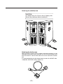
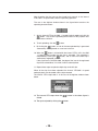
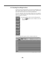
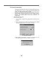
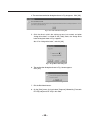
1
Non-Linear Editing System
AJ-
P
Installation Manual
Thank you for purchasing the the unit.
Please read through this manual which tells you:
O How to set up the unit (assembly precautions)
O How to check the unit’s functions (methods for checking that the
functions are operating after startup)
Reading through this Manual before proceeding with installation will
make it easier to understand the installation procedures involved.
For details on video and audio uploading, editing and other
operations, refer to the Reference Manual (AJ-SF97).
Contents
Chapter 1
Do these first! . . . . . . . . . . . . . . . . . . . . . . . . . . . . . . . . . . . . . . . . . . . . 4
1-1. Checking the accessories and attaching the stabilizer feet . . . . . . . . . . 4
1-2. Checking the AC supply voltage and precautions . . . . . . . . . . . . . . . . 6
1-3. Cable connection precautions (rear panel) . . . . . . . . . . . . . . . . . . . . . . 6
1-4. Connecting the peripheral devices and layout precautions . . . . . . . . . 7
Chapter 2
Power startup checks and AV disk inspections . . . . . . . . . . . 8
2-1. Checking the power startup . . . . . . . . . . . . . . . . . . . . . . . . . . . . . . . . . 8
2-2. Checking the SCSI device settings . . . . . . . . . . . . . . . . . . . . . . . . . . . 10
2-3. AV disk inspections . . . . . . . . . . . . . . . . . . . . . . . . . . . . . . . . . . . . . . . 12
Chapter 3
Disk-related configuration checks . . . . . . . . . . . . . . . . . . . . . . . . 13
3-1. Checking the disk settings . . . . . . . . . . . . . . . . . . . . . . . . . . . . . . . . . 13
3-2. Checking the AudioPool, VideoPool & TitlePool directories . . . . . . . . 15
Chapter 4
Checking operation using the pre-installation program . . . . . 16
4-1. Checking the uploading operation . . . . . . . . . . . . . . . . . . . . . . . . . . . 16
4-2. Check the editing functions . . . . . . . . . . . . . . . . . . . . . . . . . . . . . . . . . 24
4-3. Checking the downloading operation . . . . . . . . . . . . . . . . . . . . . . . . . 30
O Windows and Windows NT are registered trademarks of Microsoft Corporation.
O Pentium is a registered trademark of Intel Corporation.
O Adaptec, AHA and SCSISelect are registered trademarks of Adaptec Inc.
All other names of companies and products are the trademarks or registered trademarks of the companies
concerned.
–2–
Contents
Appendix A BIOS screen display . . . . . . . . . . . . . . . . . . . . . . . . . . . . . . . . . . . . . 34
A-1. Concerning BIOS information at startup . . . . . . . . . . . . . . . . . . . . . . . 34
A-2. Details on PC unit BIOS information checks . . . . . . . . . . . . . . . . . . . 34
Appendix B SCSI-BIOS Tool . . . . . . . . . . . . . . . . . . . . . . . . . . . . . . . . . . . . . . . . . . 39
B-1. Outline of SCSI-BIOS Tool . . . . . . . . . . . . . . . . . . . . . . . . . . . . . . . . . 39
B-2. How to start up SCSI-BIOS Tool . . . . . . . . . . . . . . . . . . . . . . . . . . . . 39
B-3. How to use SCSI-BIOS Tool . . . . . . . . . . . . . . . . . . . . . . . . . . . . . . . . 40
B-4. How to exit SCSI-BIOS Tool . . . . . . . . . . . . . . . . . . . . . . . . . . . . . . . . 44
Appendix C How to use Disk Administrator provided with
Windows NT . . . . . . . . . . . . . . . . . . . . . . . . . . . . . . . . . . . . . . . . . . . . . 45
C-1.Outline of Disk Administrator . . . . . . . . . . . . . . . . . . . . . . . . . . . . . . . 45
C-2.How to start up Disk Administrator . . . . . . . . . . . . . . . . . . . . . . . . . . . 45
C-3.Checking the disk settings . . . . . . . . . . . . . . . . . . . . . . . . . . . . . . . . . 46
C-4.How to inspect the disks . . . . . . . . . . . . . . . . . . . . . . . . . . . . . . . . . . . 47
C-5.How to format disks . . . . . . . . . . . . . . . . . . . . . . . . . . . . . . . . . . . . . . 49
C-6.How to exit Disk Administrator . . . . . . . . . . . . . . . . . . . . . . . . . . . . . . 52
Appendix D How to use Event Viewer provided with Windows NT . . . . . 53
D-1.Outline of Event Viewer . . . . . . . . . . . . . . . . . . . . . . . . . . . . . . . . . . . 53
D-2.How to start Event Viewer . . . . . . . . . . . . . . . . . . . . . . . . . . . . . . . . . 53
D-3.Checking system events . . . . . . . . . . . . . . . . . . . . . . . . . . . . . . . . . . . 54
D-4.How to exit Event Viewer . . . . . . . . . . . . . . . . . . . . . . . . . . . . . . . . . . 54
Appendix E Shutdown Procedure at Hang-up for Limited Edition
of the Editing Software Program . . . . . . . . . . . . . . . . . . . . . . . . . 55
To improve the operating efficiency, the devices, etc. listed in these operating instructions
are subject to change without prior notice.
–3–
Chapter
1 Do these first!
This chapter explains the procedures (setup) to prepare the purchased unit for operation and
the cautions to be heeded.
1-1. Checking the accessories and attaching the stabilizer feet . . . . . . . . . . 4
1-2. Checking the AC supply voltage and precautions . . . . . . . . . . . . . . . . 6
1-3. Cable connection precautions (rear panel) . . . . . . . . . . . . . . . . . . . . . . 6
1-4. Connecting the peripheral devices and layout precautions . . . . . . . . . 7
1-1. Checking the accessories and attaching the stabilizer feet
<Check>
Before proceeding with the connections, check that all the accessories shown
below are present and accounted for.
Do not subject the supplied mouse, keyboard or cables to strong bumps or shocks. Doing so
could damage them.
) Power cord
) Stabilizers (a4)
) mounting screws (a8)
) Keyboard
) Mouse
When the SCSI hard disk drive for external expansion
purposes is to be connected, attach one ferrite core to
one end of the SCSI I/F cable and the other one to the
other end.
) Ferrite cores (a4)
) Installation manual
(which you are now reading)
) Service support guide
–4–
) Operating
instructions
) Warranty card
Attaching the stabilizer feet
CAUTION:
To reduce the risk of injury due to tipping over,
Mount the stabilizers before installation.
Attaching the ferrite cores
When the SCSI hard disk drive for external expansion purposes is to be
connected, one of ferrite cores packed with the unit must be attached to one
end of the SCSI I/F cable and the other one must be attached to the other
end.
It is recommended that the cable shown below be used as the SCSII/F cable.
OModel No. ACK/M-WP made by Adaptec Inc.
–5–
1-2. Checking the AC supply voltage and precautions
<Check>
Use a AC voltmeter or other instrument to check that the supply voltage at
the installation location is inside the following range:
) 120 V ±10 %
Note:
Not only may the unit fail to operate properly if it has been started up with
a supply voltage outside the above range but the software programs and
data pre-installed on the system hard disk inside the unit may be
destroyed as well.
Use of an uninterruptible power supply system is recommended if the unit
is to be used in unsatisfactory power supply conditions. For details,
consult with your dealer.
1-3. Cable connection precautions (rear panel)
<Check>
Bear in mind the points listed below when connecting the accessory cables to
the unit’s rear panel. It is recommended that you proceed while referring to
the rear panel connection diagram in the Operating Instructions. (Refer to
page 12 of Operating Instructions.)
) Connect the keyboard.
) Connect the mouse.
) Check the names of the connectors on the rear panel to verify that
the keyboard has not been connected to the mouse connector or the
mouse has not been connected to the keyboard connector.
) Connect the power cord to the socket on the main unit.
) Secure the power cord using the clamp.
) Refrain from connecting the power plug to the power outlet at this
stage.
–6–
1-4. Connecting the peripheral devices and layout precautions
<Check>
Bear in mind the points listed below when connecting the computer monitor,
monitor (Video) for monitoring the pictures and other peripheral devices to
the unit. It is recommended that you proceed while referring to the rear panel
connection diagrams in the Operating Instructions. (Refer to pages 13–16 of
Operating Instructions.)
For details on the handling of peripheral devices, refer to the operating
instructions accompanying each device concerned.
) Connect the peripheral devices while power to the unit and peripheral
devices is off.
) Before moving the unit, turn its power off.
Do not move the unit while the power is still on.
) Install the unit in a flat and stable location.
) At the installation stage, ensure that the connectors and cables
protruding from the unit’s rear panel do not make contact with any
objects in the vicinity.
) At the installation stage, do not drop the keyboard or mouse, and
take care not to run their cables underneath the unit or peripheral
devices.
) Do not place objects on top of the unit.
) Leave a sufficient clearance around the unit in order to improve the
ventilation inside the unit.
) Do not place food or drinks in the vicinity of the unit.
Morsels of food or spilled drinks can cause trouble.
) Check that you have not forgotten to connect the VGA cable between
the unit and the monitor for the computer.
) Check that you have not forgotten to connect the video cable
between the unit and monitor (Video) for monitoring the pictures.
) Check that you have not forgotten to connect the unit and any other
peripheral devices.
) Check that all the devices required have been connected, and insert
the power plugs of the unit and peripheral devices into the power
outlets.
) When the SCSI hard disk drive for external expansion purposes is to
be connected:
Attach one of the ferrite cores packed with the unit to one end of the
SCSI I/F cable and the attach the other one to the other end.
–7–
Chapter
2 Power startup checks and AV disk inspections
This chapter explains the checks that must be conducted on the basic hardware settings and
basic inspections of the AV disks after the unit’s power switch has been set to the ON
position.
When conducting the checks and inspections described in this chapter, do not turn off the
power or reset the system unnecessarily. Doing so may change or destroy the pre-installed
software programs or data.
For details on turning off the power and resetting the system, refer to the
descriptions given for the items concerned.
2-1. Checking the power startup . . . . . . . . . . . . . . . . . . . . . . . . . . . . . . . . . 8
2-2. Checking the SCSI device settings . . . . . . . . . . . . . . . . . . . . . . . . . . . 10
2-3. AV disk inspections . . . . . . . . . . . . . . . . . . . . . . . . . . . . . . . . . . . . . . . 12
2-1. Checking the power startup
When the unit’s power switch is set to ON, the unit’s basic test is
automatically conducted, and its results can be checked out by beep tones
and displays which appear on the computer monitor.
After the power switches of the computer monitor, monitor (Video) for
monitoring the pictures and other peripheral devices have been set to ON,
set the unit’s power switch to ON and conduct the checks described below at
startup.
If trouble has been detected as a result of conducting the checks, refer to the
“Troubleshooting” section in the Operating Instructions. (Refer to pages
20–27 of the Operating Instructions.)
Since it takes very little time to check the displays on the computer monitor,
you will find it easier to perform the checks if you quickly glance through the
whole of this section and the BIOS screen displays in Appendix A (pages
34–38) and understand what is involved.
For details on how to adjust the monitor and otherwise handle any of the
peripheral devices, refer to the operating instructions accompanying each
device concerned.
Note:
If a monitor display which should have been checked during startup has
been overlooked, the unit must be rebooted so that it can be checked.
Under no circumstances must the power be turned off or the system
reset while white characters appear on a blue background during
startup.
Wait until the Windows NT flag appears, and then reboot the unit using
the system reset switch on the unit’s front panel.
–8–
Checking the LEDs on the unit’s front panel
<Check>
) Check that the two disk access lamps light up and flash when the
power is turned on.
Checking the computer monitor displays (BIOS start screen) during
startup
<Check>
) Is the memory size value (standard 256 MB) correct?
) Did the CD-ROM drive name appear (for an instant)?
) Did the name of the system hard drive appear?
(Refer to the BIOS screen displays in Appendix A.)
) Did the SCSI card name appear?
(Refer to the BIOS screen displays in Appendix A.)
) Did all the SCSI disk names appear?
(Refer to the BIOS screen displays in Appendix A.)
) Did the PCI device list appear?
(Refer to the BIOS screen displays in Appendix A.)
–9–
2-2. Checking the SCSI device settings
In this section the SCSI-BIOS Tool is used to check the SCSI device settings.
You will find it easier to perform the checks if, before starting the actual
procedure, you quickly glance through SCSI-BIOS Tool items B-1–B-3
(pages 39–43) in Appendix B and understand how the settings of the parts
corresponding to the items to be checked in this section are displayed.
In particular, the following parts in B-3 must be understood.
(1) SCSI device configuration check
(2) SCSI ID check
If items with different settings have been detected as a result of conducting
the checks, refer to the explanation given in
¬When the SCSI device parameters are wrong¬
which is found in B-3 of Appendix B, and to the “Troubleshooting” section in
the Operating Instructions. (Refer to pages 20–27 of Operating Instructions.)
When the checks in this section have been completed with no errors found,
proceed to the next section [2-3. AV disk inspections] without exiting the
SCSI-BIOS Tool.
1. After the series of checks described in Section 2-1 (Checking the power
startup) have been completed with no errors found, reboot the unit and
check the SCSI device settings.
Note:
If, upon completion of the checks in the previous section, the screen
displays during the startup procedure have reached the white characters
on a blue background status, do not turn off the power or reset the
system until the display status changes.
If either step is to be performed, wait until the Windows flag appears on
the screen, and then reboot the unit using the reset switch.
2. Check the SCSI device settings following the instructions in “(1) SCSI
device configuration check” and “(2) SCSI ID check” in B-3 (pages 40,
41) of Appendix B (SCSI-BIOS Tool).
– 10 –
SCSI device configuration checks (1)
(Conduct the checks for both channels A and B.)
<Check>
O Check the SCSI Channel Interface Definitions.
) Is the Host Adapter SCSI ID set to “7”?
) Is the SCSI Parity Checking set to “Enable”?
) Is the Host Adapter SCSI Termination set to “Automatic”?
SCSI device configuration checks (2)
(Conduct the checks for both channels A and B.)
<Check>
O Check the parameters of all the SCSI-ID #0–#15 devices in SCSI
Device Configuration.
(Check that the parameters of all the devices are set as shown below.)
) Is the Maximum Sync Transfer Rate set to “160”?
) Is the Initiate Wide Negotiation set to “yes”?
) Is the Enable Disconnection set to “yes”?
) Is the Send Start Unit Command set to “yes”?
) Is the Enable Write Back Cache set to “N/C”?
) Is the BIOS Multiple LUN Support set to “no”?
) Is the Include in BIOS Scan set to “yes”?
SCSI ID checks
(Conduct the checks for both channels A and B.)
<Check>
) Does “Adaptec SCSI Card 39160” appear for SCSI ID #7?
– 11 –
2-3. AV disk inspections
In this section, the AV disks are inspected using the SCSI-BIOS Tool.
These inspections check for defects in the AV disks as recording media. (It
takes about 2 hours to conduct all the inspections in this category.)
1. To return the screen display to the inspection menu selection, press the
[Esc] key several times until the message box shown below is displayed.
Exit Utility ?
Yes
No
2. After selecting [No], press the [Enter] key, follow the displays and return
the device channel (channel A, B) selection screen.
3. Inspect the disks following the instructions on “(3) Inspecting the disk
media” in B-3 (pages 46, 47) of Appendix B (SCSI-BIOS Tool).
Channel A SCSI disk checks
<Check>
) Did “Verify Disk” of the SCSI ID #1 disk end with “Disk Verification
Complete”?
) Did “Verify Disk” of the SCSI ID #2 disk end with “Disk Verification
Complete”?
Channel B SCSI disk checks
<Check>
) Did “Verify Disk” of the SCSI ID #0 disk end with “Disk Verification
Complete”?
) Did “Verify Disk” of the SCSI ID #1 disk end with “Disk Verification
Complete”?
) Did “Verify Disk” of the SCSI ID #2 disk end with “Disk Verification
Complete”?
4. If all the disks have been inspected with no errors found, refer to B-4
(page 44) in Appendix B, and exit the SCSI-BIOS Tool.
– 12 –
Chapter
3 Disk-related configuration checks
This chapter describes the checks on the disk-related settings which are conducted on the
startup screen of Windows NT, the operating system used by the unit, and the inspections
conducted on the AV disks to verify whether they can be used by this system.
The inspections described in this chapter are conducted after the Windows NT startup screen
appears normally after the power to all the units and devices has been turned on.
For details on the checks and inspections conducted prior to the appearance of the Windows
NT startup screen, refer to Chapters 1 and 2 of this manual.
3-1. Checking the disk settings . . . . . . . . . . . . . . . . . . . . . . . . . . . . . . . . . 13
3-2. Checking the AudioPool, VideoPool & TitlePool directories . . . . . . . . 15
3-1. Checking the disk settings
The checks in this section are performed after the series of checks described
in the previous chapter have been completed with no errors found.
When the sequence of power startup steps is completed and the waiting-tolog-on dialog box has appeared on the screen, follow the instructions in the
box and complete the logging on procedure for Windows NT.
On the startup window after Windows NT log-on, check the disk settings in
this section using the Disk Administrator which is a Windows NT
management tool.
Before starting the actual procedure, you will find it easier to perform the
checks if you quickly glance through items C-1–C-3 (pages 45, 46) of
Appendix C how to use Disk Administrator provided with Windows NT and
understand how the settings of the parts corresponding to the items to be
checked in this section are displayed.
If items with wrong settings have been detected as a result of conducting the
checks, refer to the explanations with the ¬ marks in the sections concerned
in Appendix C and to the “Troubleshooting” section in the Operating
Instructions. (Refer to pages 20–27 of Operating Instructions.)
– 13 –
O Start up the Disk Administrator following the instructions in C-2 (page 45)
of Appendix C.
Disk volume-related status information check using the
Disk Administrator
<Check>
) Are 6 disks (excluding the CD-ROM) displayed altogether?
) Is one CD-ROM drive displayed?
) Are the names of the drives for disk 0 set to “C:” or “D:”?
) Is “NTFS” the format of disk 0 for both “C:” and “D:”?
) Is the name of the drive for disks 1 through 4 set to “O:”?
) Is the name of the drive for disk 5 set to “L:”?
) Is “RTLFS” the format of disks 1 through 5?
) Is the name of the CD-ROM drive set to “E:”?
If the checks in this section have been completed error-free, exit the Disk
Administrator by following the procedure described in item C-6 of Appendix
C.
– 14 –
3-2. Checking the AudioPool, VideoPool & TitlePool directories
In this section, the Windows NT Explorer is used to check the making of the
AudioPool, VideoPool and TitlePool directories on the Windows NT startup
screen.
1. If there is an application now starting up in Windows NT, exit the
application and start the procedure from the Windows NT startup screen.
2. On the [Start] menu, click [Program] 5 [Windows NT Explorer] to start.
3. Click the RTLFS-Volume(L:) drive under My Computer on the left side of
the divided window.
Check the names of the directories which appear in the right
side of the divided window.
<Check>
) Does the AudioPool directory (L: \ AudioPool) appear for drive “L:”?
4. On the left side of the divided window, click the RTLFS-Volume(O): drive
under “My Computer.”
Check the names of the directories which appear on the right
side of the divided window.
<Check>
) Does the VideoPool directory (O:\VideoPool) appear for drive “O:”?
) Does the system directory (O:\system) appear for drive “O:”?
5. On the left side of the divided window, click the System2(D): drive under
“My Computer.”
Check the names of the directories which appear on the right
side of the divided window.
<Check>
) Does the TitlePool directory (D:\TitlePool) appear for drive “D:”?
6. When the checks in this section have been completed with no errors
found, click
at the top right of the Explorer window, exit the Windows
NT Explorer, and return to the Windows NT startup screen.
– 15 –
Chapter
4
Checking operation using the
pre-installation program
This chapter explains after the unit has been installed how to conduct comprehensive
operation checks on the hardware of the unit using the limited edition of the editing software
program which is pre-installed in the unit.
Note:
Do not install the editing program until the checks described in this chapter have been
completed. Otherwise, it may no longer be possible to run the limited edition of the
program which was pre-installed.
After the power to the unit has been turned on, wait until the Windows NT startup screen has
appeared without any problem. It is only after this that all the checks described in this
chapter are to be performed. For details on the checks and inspections before this screen
appears, refer to Chapters 1 and 2 of this Manual.
When an external VTR is to be used, connect the external input and output devices to both
the component and composite connectors before starting the checks.
4-1. Checking the uploading operation . . . . . . . . . . . . . . . . . . . . . . . . . . . 16
4-2. Check the editing functions . . . . . . . . . . . . . . . . . . . . . . . . . . . . . . . . . 24
4-3. Checking the downloading operation . . . . . . . . . . . . . . . . . . . . . . . . . 30
4-1. Checking the uploading operation
Proceed with the checks in this section after the series of checks described in
the previous chapters have been completed with no errors found.
In this section, the limited edition of the pre-installed editing software program
is used to check the uploading operation on the startup screen which appears
after Windows NT log-on.
If errors have been detected in the settings as a result of conducting the
checks, refer to the explanations enclosed within the ¬ marks in the sections
concerned in Appendix C and to the “Troubleshooting” section in the
Operating Instructions. (Refer to pages 20–27 of Operating Instructions)
1. Double-click the Panasonic NLE System icon (shown below) on the
Windows NT startup screen to start the limited edition of the editing
software program.
(Startup may take ten seconds or so.)
– 16 –
2. The screen shown below now appears.
<Check>
) Did the screen shown below appear as a result of starting the limited
edition of the editing software program?
Double-click Top Bin if the Bin window of Top Bin is not open.
– 17 –
3. Click the
button from the Toolbox at the top left
of the screen to start the digitizer.
VTR control checks
<Check>
) Did the digitizer window as shown below appear?
The device list box for selecting the VTRs and other devices is located at the
top left of the digitizer window.
The VTR unit to be controlled can be changed by changing the device.
– 18 –
<Check>
) Is “Internal VTR (50Mx2)” shown for Device on the digitizer window?
4. If “Internal VTR (50Mx2)” is not shown for Device, click the
mark at the
right end of the list box to display the device list, and select “Internal VTR
(50Mx2)” which is the system’s internal VTR.
5. Insert the DVCPRO tape with the recorded images into the system’s
internal VTR, and wait for its loading to be completed.
6. Play back the tape in the internal VTR using the VTR function buttons on
the digitizer window.
The area shown below of the digitizer window is where the VTR function
buttons are located. Clicking one of these buttons using the mouse
initiates the operation of the button clicked.
<Check>
) Did the internal VTR playback start in the 50M a2 speed mode when
the
button was clicked?
Check the internal VTR’s playback output by viewing the video monitor.
) Were the internal VTR playback images in the 50M a2 speed mode
affected by noise or disturbances during the playback of the tape
which was recorded normally?
) Was the sound played back at the a2 speed?
– 19 –
After checking that the tape can be played back normally in the internal
VTR’s 50M a2 speed mode, check the uploading operation.
The area in the digitizer window shown in the figure below contains the
uploading function buttons.
7. Set the internal VTR to the 50M a2 speed playback mode and click the
button. This starts the uploading of the internal VTR’s playback data
to the internal AV disk.
8. To exit uploading, click the
button.
9. By clicking the
button, an icon of the now uploaded clip is generated
automatically and registered as a new icon in the bin.
10. When the
button is clicked while the internal VTR is still in the 50M
a2 speed playback mode, the next data is uploaded. The uploading is
completed by clicking the
button, and an icon of the new clip is
automatically registered in the bin.
If the clip format is DVCPRO 50M, the edge of the icon of the registered
clip will be colored blue; if it is 25M, it will be colored yellow.
11. Repeat these steps to upload multiple clips to the AV disk.
When all the clips have been uploaded, the internal VTR 50M a2 speed
mode playback must be ended and the tape removed.
The internal VTR’s stop button is in the area of the digitizer window shown
below.
12. The internal VTR stops when the
clicked.
13. The tape is ejected by clicking the
– 20 –
button in the above figure is
button.
Precautions when checking the uploading operation
While the uploading operation is being checked, do not click on any parts
except those provided on the digitizer window. Doing so may make it
impossible to conduct a proper check on the uploading operation.
<Check>
) Did the color of the area with the “RecStart” letters change when the
button was clicked?
) Did the color of the area with the “RecStart” letters on the
change to white when the
button was clicked?
button
) Was the new icon of the uploaded clip registered in the bin when the
button was clicked?
) Did the internal VTR 50M a2 speed mode playback stop when the
button of the internal VTR was clicked after all the clips were
uploaded?
Check the internal VTR’s playback output by viewing the video monitor.
This now completes the internal VTR’s uploading operation.
Next, the playback of the uploaded data is checked.
– 21 –
14. The uploaded data can be played by inputting the space key after the clip
registered in the bin has been clicked (selected).
15. Check the clip’s playback images on the monitor (video) for monitoring
the pictures.
16. Playback automatically stops at the end of the selected clips.
To stop playback at any time, input the space key again.
<Check>
) Were the clips registered in the bin selected when they were clicked?
) Was the selected clip played (at a1 speed) when the space key was
pressed?
) Did the selected clip stop playing when the space key was pressed
again?
) Was the playback AV of the selected clip affected by noise or
disturbances?
All the playback images of the clips are checked on the monitor (video) for
monitoring the pictures.
This now completes the check for the uploading operation and the uploaded
data for the internal VTR’s 50M a2 speed mode.
To conduct further checks on the uploading for
O Internal VTR (50Mx1): Internal VTR 50M a1 speed,
O Internal VTR (25Mx4): Internal VTR 25M a4 speed and
O Internal VTR (25Mx1): Internal VTR 25M a1 speed,
select “Internal VTR (50Mx1)”, “Internal VTR (25Mx4)” and “Internal VTR
(25Mx1)” as the device displayed on the VTR control panel, and conduct the
same checks described above as for “Internal VTR (50Mx2).”
Even with a system that connects an external VTR or a system which uses a
microphone for uploading, select the name of a device displayed from among
those listed below, and conduct the same checks as the ones conducted so
far. The table below shows the settings for the input/output signals, data
format during uploading and RS-422 port in the limited edition of the editing
software program.
Connect the signal lines and conduct the checks in accordance with these
settings.
Name of device
displayed
Data format during
uploading
RS-422
connector
Analog
DVCPRO
Port 1
Digital
DVCPRO 50
Port 1
SDI
SDI embedded
DVCPRO 50
Port 2
———
Mic input jack
on system’s
front panel used
———
———
Video input
Audio input
External VTR 1
Composite
External VTR 2
Component
External VTR 3
Microphone
– 22 –
Checks before using an external VTR or microphone for
uploading
<Check>
) Has the RS-422A cable been connected properly between the system
and external VTR?
Refer to the operating instructions of each for details on the connection
methods.
) Has the external VTR been set so that it can be operated by remote
control?
Refer to the operating instructions of the external VTR for details on the
setting method.
) Is the correct device name displayed on the digitizer window of the
system and limited edition of the editing software program?
17. After the checks (only if necessary) for the uploading operation using the
external VTR have been completed error-free, click
at the top right of
the digitizer window to close the window.
Do not exit the Toolbox since the limited edition of the editing software
program will be used in the next section as well.
– 23 –
4-2. Checking the editing functions
Proceed to check the editing operations using the same limited edition of the
editing software program which was used in the last section. Upload several
clips to the AV disk in advance to use in checking the operations.
If the clips registered in the bin have been erased, return to the previous
section (4-1.), create several fresh clips and play them back to check that no
noise or disturbances are present.
The sequence editor is used to check the editing operations.
1. Click the
sequence editor.
button from the Toolbox to start the
The screen shown below appears when the sequence editor starts.
– 24 –
<Check>
) Did the sequence editor screen appear when the
clicked?
button was
2. When the sequence editor has started, drag and drop the clips registered
in the bin onto the video track, and create the video sequence.
The length of the dropped clip is indicated by a proportionately long
rectangle, and the clip icon appears at the far left of the rectangle. The figure
below shows an example of the display.
<Check>
) Was it possible to drag and drop the clip on the video track?
3. In the same way, drag and drop several clips on the video track and
create the video sequence.
The clips on the video tracks are automatically color-coded.
When a clip extends beyond the sequence editor
screen, click the “+” or “–” button at the top of the
window to change the time axis. The displayed
length of a clip can be shortened using the “–”
button.
A video sequence created by only drag and drop procedures is automatically
set to the cut editing mode.
The clips are automatically positioned without gaps, and the
mark
appears at each join.
– 25 –
<Note>
The limited edition of the editing software program limits the number of clips
in the sequence editor to 30. This number includes the clips on the audio
tracks.
For instance, in the case of DVCPRO 50M format clips (usually one video
and four audio channels), the number of clips has already reached 5.
In addition, the specifications of the sequence editor do not permit DVCPRO
50M and DVCPRO 25M clips to be mixed so data in the same format must
be used to create a video sequence consisting of multiple clips.
The figure below shows an example of the display of a video sequence
consisting of two clips.
<Check>
) Was it possible to drag and drop several clips on the video track?
) Did the
mark appear at each join between the clips as shown in
the figure above?
– 26 –
After creating the video sequence, play it back and check it.
The sequence is played back using the function buttons
(shown on the left) located at the top of the sequence
editor window.
4. Click the
button to move the play start position to the beginning of the
video sequence.
5. Click the
button to start playing the video sequence.
6. The playback images are now output to the monitor (video) for monitoring
the pictures.
7. The cursor appears on the video track to indicate the current playback
position while the video sequence is being played.
8. Playback is automatically ended at the end of the video sequence.
9. Click the
<Check>
button to suspend playback at any time.
) Did the playback of the video sequence start when the
clicked?
button was
) Did the playback of the video sequence stop when the
clicked?
button was
) Was there any noise or disturbances in the playback AV of the video
sequence?
Check the playback images visually on the monitor (video) for monitoring
the pictures.
Next, check the operation for the video 2-channel simultaneous playback in
which video effects are utilized.
10. Use the mouse to click the first clip in
the video sequence in which multiple
clips were placed on the video track.
11. As shown in the figure on the right,
some square dots called “grids”
appear on the clip.
12. Among these grids, select the middle grid on the right side by clicking it
with the mouse.
Keep the mouse in the clicked (dragged) status.
13. The color of the selected grid now turns from white to red.
14. Keep dragging the grid which has now turned red and move it toward the
left before releasing the mouse at the appropriate position.
(This shortens the duration of the clip concerned.)
– 27 –
15. Next, select the grid on the far left of
the same clip by clicking it with the
mouse.
Keep the mouse in the clicked
(dragged) status.
16. The color of the selected grid now
turns from white to red.
17. Keep dragging the grid which has turned red and move it toward the right
before releasing the mouse at the appropriate position.
18. The join between the first and second clips changes to a
mark as
shown in the figure above. (The default video effect is dissolve.)
<Check>
) Did the join between the clips change to a
figure above?
mark as shown in the
19. If necessary, repeat steps 11 through 18 for other clips, and add the
video effect to the video sequence.
An example of video timeline containing the video effect is shown below.
– 28 –
After creating the video sequence, check its playback.
The function buttons (see figure at left) at the top of the
sequence editor window are used for the playback
operations.
20. Click the
button to move the playback start position to the start of the
video sequence.
21. The playback of the video sequence is started when the
clicked.
button is
22. The playback images are output to the video monitor.
23. While the video sequence is being played back, the playback position is
indicated on the video track by the cursor.
24. Playback ends automatically when the end of the video sequence is
reached.
25. To stop the playback at any time, click the
<Check>
button.
) Did the video sequence playback start when the
clicked?
button was
) Did the video sequence playback stop when the
clicked?
button was
) Were the audio and video playback of the video sequence affected by
noise or disturbances?
Check the playback images by viewing the video monitor.
After checking the editing operations in the video sequence, destroy the
video sequence created.
26. Click the
mouse.
mark at the top right of the sequence editor window with the
27. The window shown below now appears.
28. Click the
button to exit the sequence editor.
This completes the editing operation checks.
Do not exit the Toolbox since the limited edition of the editing software
program will be used in the next section as well.
– 29 –
4-3. Checking the downloading operation
In this section, the downloading operation using the limited edition of the
editing software program is checked.
To check the downloading operation, use the clips which were already
uploaded by the digitizer and registered in the bin. (Check that the clips used
are free from noise and disturbances.)
Ensure that a cassette tape enabling test recording is already loaded in the
system’s internal VTR.
<Note>
Clips must be used to check the downloading operation. If the video
sequence used in section 4-2 is downloaded, it will not be recorded properly
on the tape.
Use the Record To Video tool to check the downloading
operation.
1. Click the
button from Toolbox to start the
Record To Video tool.
When Record To Video tool is started, the screen shown below appears.
– 30 –
<Check>
) Did the Record To Video tool screen appear when the
was clicked?
button
) Has a cassette tape enabling test recording been loaded in the
system’s internal VTR?
) Is “Internal VTR (50Mx2)” shown as the device display?
2. If “Internal VTR (50Mx2)” is not displayed at the Device on the Record To
Video window, click the
mark at the far right of the list box to display
the device list, and select “Internal VTR (50Mx2)” which is the system’s
internal VTR.
3. Select (by clicking) “Immediate” among the selector buttons that indicate
the selectable recording modes on the Record To Video window.
<Check>
) Did “Immediate” among the recording mode selector buttons turn
light blue?
4. Use the mouse to drag the DVCPRO 50M clip (clip with the blue-edged
icons) registered in the bin, and drop it in the Clip View Area on the
Record To Video window.
5. The image of the first frame of the clip dropped in the Clip View Area is
displayed in the area.
<Check>
) Was the image of the first frame of the clip concerned displayed in
the Clip View Area?
– 31 –
6. Click the
button in the Record To Video window to start
downloading. The letters of “RecStart” on the button turn red.
The image being downloaded can be checked on the video monitor.
When the downloading is completed, the letters of “RecStart” on the
button return to their original color.
<Check>
) Did the “RecStart” letters turn red when the
clicked to start downloading?
button was
) Was the image of the downloaded clip displayed on the video
monitor?
button return to their original color
) Did the letters of the
after the images were downloaded?
If the answer to the above questions was “yes” in each case, downloading is
completed.
Next, play back the tape with the downloaded images to check the recording
results.
<Notes>
If the tape is played back using the
button on the Record To Video
window when “Internal VTR (50Mx2)” is the Device on the Record To Video
window, the images of every other frame will be displayed on the video
monitor.
If preview playback at a1 speed is performed for a DVCPRO 50M tape by
this system using the
button, control over the head tracks will not be
exercised for the tape’s recording tracks. This means that even when the
data has been recorded properly, the images may be affected by noise or
disturbances when they are played back, rendering this operation unsuitable
for checking the downloading.
The images are played back properly by performing preview playback at a1
speed for a DVCPRO 25M tape.
Therefore, the system must be set to the a1 speed mode for playback if a
DVCPRO 50M tape is to be played back normally.
To set the system to the 50M a1 speed mode, select “Internal VTR (50Mx1)”
for the Device on the digitizer or Record To Video window.
– 32 –
7. Click the
mark at the far right in the Device list box on the Record To
Video window to display the device list, and select “Internal VTR
(50Mx1).”
8. Operate the internal VTR using the VTR control panel on the Record To
Video window, and return to the approximate point where the
downloaded images start on the tape.
9. Click the
button among the VTR controls to play back the internal
VTR’s tape at the a1 speed, and check the downloaded data.
10. The playback images are output to the video monitor.
11. To stop playback, click the
<Check>
button.
) Did the tape playback at the a1 speed start when the
clicked?
button was
) Did the tape playback at the a1 speed stop when the
clicked?
button was
) Were the tape’s playback images affected by noise or disturbances?
Check the playback images by viewing the video monitor.
This now completes the check for the downloading operation and the
downloaded data for the internal VTR’s 50M a2 speed mode.
To conduct further checks on the downloading for
O Internal VTR (50Mx1): Internal VTR 50M a1 speed and
O Internal VTR (25Mx4): Internal VTR 25M a4 speed,
select “Internal VTR (50Mx1)” and “Internal VTR (25Mx4)” as the device
displayed on the VTR control panel, and conduct the same checks described
above as for “Internal VTR (50Mx2).”
<Note>
Consult your local dealer regarding installation of the AJ-SF97 non-linear
editing software.
– 33 –
Appendix
A BIOS screen display
A-1. Concerning BIOS information at startup
The following BIOS information items are displayed on the computer’s
monitor immediately after the unit’s power is turned on.
Basic inspections of the PC unit hardware of the unit can be conducted by
checking the items displayed.
(1) Award Modular BIOS version
(2) Type of CPU
(3) Main memory size (on completion of memory test)
(4) System disk drive acquisition status (system disk drive name)
(5) CD-ROM drive acquisition status (CD-ROM drive name)
(6) SCSI card (ASC-39160) SCSI-BIOS startup information
(7) SCSI-HDD (for 5 units) connection information
(8) PCI device information
A-2. Details on PC unit BIOS information checks
The information to be checked on the computer’s monitor display immediately
after the unit’s power is turned on in Section 2-1 (Checking the power startup)
of Chapter 2 consists of the following six items. Which part of the screen
should be checked is described for each item in turn.
(1) Main memory size
(2) CD-ROM drive name
(3) System disk drive name
(4) SCSI card name
(5) SCSI disk drive names (for 5 units)
(6) Plug & Play (PnP) device list
– 34 –
(1) Main memory size
The figure below shows the screen which appears after the PC unit’s main
memory (size: 256 MB) check has been completed with no errors found.
“262144 KB (256 MB)” is displayed as the main memory size when the unit is
shipped.
BIOS version display
Award Modular BIOS v6.0, An Energy Star Ally
Copyright(C) 1984-95, Award Software, Inc.
ASUS CUBX-L ACPI BIOS Revision 1007
Intel(R) Pentium(R) III 850MHz Processor
Memory Test : 262144K OK
Main memory size
Award Plug and Play BIOS Extension v1.0A
Initialize Plug and Play Cards...
PNP Init Completed
Copyright (C) 1995, Award Software, Inc.
– 35 –
(2) CD-ROM drive name and (3) System disk drive name
The figure below shows the screen on which the CD-ROM drive and system
disk drive are checked and which displays the device information acquired
from the devices.
The screen shows that “CR-585” is the unit’s CD-ROM drive and that the
“IBM-DTLA-307030” made by IBM is the unit’s system disk drive (HDD).
Award Modular BIOS v6.0, An Energy Star Ally
Copyright(C) 1984-95, Award Software, Inc.
ASUS CUBX-L ACPI BIOS Revision 1007
Intel(R) Pentium(R) III 850MHz Processor
Memory Test : 262144K OK
Award Plug and Play BIOS Extension v1.0A
Initialize Plug and Play Cards...
PNP Init Completed
Copyright (C) 1995, Award Software, Inc.
The Chip Away Virus(R) On Guard
Detecting
Detecting
Detecting
Detecting
Primary Master....
Primary Slave.....
Secondary Master..
Secondary Slave...
System disk drive name
IBM-DTLA-307030
MATSHITA CR-585
None
None
CD-ROM drive name
– 36 –
(4) SCSI card name and (5) SCSI disk drive names (for 5 units)
The figure below shows the screen which displays the BIOS installation of the
SCSI card (ASC-39160) inserted into the PCI slot and the information for the
five SCSI disk drives connected to the SCSI card.
Normally, information for all five drives is displayed as shown in the figure.
Initialize Plug and Play Cards...
PNP Init Completed
Detecting Primary Master.... IBM-DTLA-307030
Detecting Primary Slave..... MATSHITA CR-585
The SCSI card name must include
“39160”.
Adaptec SCSI Card 39160 SCSI BIOS vX.XX
(c) 1997 Adaptec, Inc. All Rights Reserved.
222 Press <Ctrl><A> for SCSISelect(TM) Utility! 111
Ch A,
Ch B,
SCSI
SCSI
SCSI
SCSI
SCSI
ID:
ID:
ID:
ID:
ID:
1
2
0
1
2
IBM
IBM
IBM
IBM
IBM
DDYS-T18350M
DDYS-T18350M
DDYS-T18350M
DDYS-T18350M
DDYS-T18350M
160
160
160
160
160
-
Hard
Hard
Hard
Hard
Hard
Disk0
Disk1
Disk2
Disk3
Disk4
“160” must appear as the
SCSI bus speed.
The disk drive names must appear for each SCSI
ID without fail.
The SCSI ID for Ch A and Ch B must appear in order as
1 and 2 and 0 to 2, respectively.
The SCSI channels must appear as Ch A and Ch B.
Two disc drive displays must appear for Ch A and three for Ch B.
– 37 –
(6) PCI device list
The figure below shows the device list screen which appears after the SCSI
device display. The PCI device list occupies the bottom half of the screen.
The PCI device list appears only for a short while at the unit’s startup stage.
Check that the list is displayed and that the Device Class and IRQ sections
are displayed.
CPU Clock
: 850MHz
Cache Memory
: 512K
Diskette Drive A
Diskette Drive B
Pri. Master Disk
Pri. Slave Disk
Sec. Master Disk
Sec. Slave Disk
:
:
:
:
:
:
Display Type
Serial Port(s)
DRAM TYPE
SPD On Module(s)
Data Integrity
:
:
:
:
:
1.44M, 3.5 in.
None
20576MB, UDMA2
CD-ROM, MODE 4
None
None
EGA/VGA
3FB 2FB
SDRAM
Yes
Non-ECC
<BIOS:> BIOS update data incorrect (CPUID=00000619), Update not loaded.
PCI device listing.....
Bus No. Device No. Func No. Vender ID
0
0
0
0
1
2
2
2
3
3
3
4
4
11
11
0
2
3
4
1
2
5
1
2
0
1
0
0
0
0
0
0
0
8086
8086
9005
9005
102B
123F
1131
1131
1131
123F
102B
Device ID
7111
7112
00C0
00C0
0525
8120
5400
5400
5400
8120
8010
Device Class
IRQ
IDE Controller
14/15
Serial bus controller
9
Mass storage controller 10
Mass storage controller 5
Display controller
11
Multimedia device
10
Multimedia device
5
Multimedia device
9
Multimedia device
11
Multimedia device
10
Processors
NA
It must be checked that Device Class and IRQ are
displayed.
– 38 –
Appendix
B SCSI-BIOS Tool
B-1. Outline of SCSI-BIOS Tool
The SCSI-BIOS Tool makes it possible to:
O Check and change the SCSI host adapter settings.
O Check the SCSI device settings which may conflict with other device
settings.
B-2. How to start up SCSI-BIOS Tool
1. If Windows NT has been started up, click [Start] 5 [Shutdown] to restart
Windows NT.
If Windows NT has not been started up, set the power to [ON].
2. When the following message appears on the screen while the PC is
starting up, press [Ctrl] + [A] on the keyboard.
Adaptec SCSI Card 39160 SCSI BIOS vX.XX
(c) 1997 Adaptec, Inc. All Rights Reserved.
222 Press <Ctrl><A> for SCSISelect(TM) Utility! 111
3. A dialog box with an underlying blue tone is opened, and the selection
screen shown below appears.
Bus:Device:Channel
00:0B:A
00:0B:B
– 39 –
B-3. How to use SCSI-BIOS Tool
(1) Checking the SCSI device configuration
1. Press the [:] or [;] arrow key to highlight the SCSI channel to be
checked, and then press the [Enter] key to select the channel.
(Press the [Esc] key to return to the previous menu.)
2. The selection screen shown below now appears. Press the [:] or [;]
arrow key to highlight the [Configure/View Host Adapter Settings] item, and
press the [Enter] key.
(Press the [Esc] key to return to the previous menu.)
Options
Configure/View Host Adapter Settings
SCSI Disk Utilities
3. The selection screen shown below now appears. Press the [:] or [;]
arrow key to highlight the [SCSI Device Configuration] item, and press the
[Enter] key.
(Press the [Esc] key to return to the previous menu.)
Configuration
SCSI Channel Interface Definitions
Host Adapter SCSI ID................. 7
SCSI Parity Checking................. Enable
Host Adapter SCSI Termination........ Automatic
Additional Options
Boot Device Options.................. Press<Enter>
SCSI Device Configuration............ Press<Enter>
Advanced Configuration Options....... Press<Enter>
4. The parameters for SCSI devices #0 to #15 now appear. Check that the
parameters of all the devices are set as shown below.
(Press the [Esc] key to return to the previous menu.)
SCSI Device ID
SCSI Device Configuration
#0
#1
-------
Sync Transfer Rate(MB/sec)....
Initiate Wide Negotiation.....
Enable Disconnection..........
Send Start Unit Command.......
160
yes
yes
yes
160
yes
yes
yes
-------------------------
#15
160
yes
yes
yes
Options Listed Below Have NO EFFECT if the BIOS is Disabled
Enable Write Back Cache....... N/C
BIOS Multiple LUN Support..... no
Include in BIOS Scan.......... yes
– 40 –
N/C
no
yes
-------------------
N/C
no
yes
¬ When the SCSI device parameters are wrong ¬
O Change the parameters.
To change a parameter, press the [:] or [;] arrow key to highlight the
item to be changed.
Next, press the [Enter] key. A pop-up menu will appear, and the
selectable settings are displayed.
Highlight the item to be selected, and press the [Enter] key to make the
selection.
(2) Checking the SCSI IDs
1. Press the [:] or [;] arrow key to highlight the SCSI channel to be
checked, and press the [Enter] key to make the selection.
(Press the [Esc] key to return to the previous menu.)
2. The selection screen shown below now appears. Press the [:] or [;]
arrow key to highlight the [SCSI Disk Utilities] item, and press the [Enter]
key.
(Press the [Esc] key to return to the previous menu.)
Options
Configure/View Host Adapter Settings
SCSI Disk Utilities
3. Check that the screen shown below now appears.
(Press the [Esc] key to return to the previous menu.)
Select SCSI
SCSI ID #0 :
SCSI ID #1 :
SCSI ID #2 :
SCSI ID #3 :
SCSI ID #4 :
SCSI ID #5 :
SCSI ID #6 :
SCSI ID #7 :
SCSI ID #8 :
SCSI ID #9 :
SCSI ID #10 :
SCSI ID #11 :
SCSI ID #12 :
SCSI ID #13 :
SCSI ID #14 :
SCSI ID #15 :
Disk and press <Enter>
No Device
IBM DDYS-T18350M
IBM DDYS-T18350M
No device
No device
No device
No device
Adaptec SCSI Card 39160
No device
No device
No device
No device
No device
No device
No device
No device
The figure on the left
shows the information for
channel A.
With channel B, IBM
DDYS-T18350M is
displayed for #0 as well.
¬ When there are not enough devices ¬
O Check that the power supply has been connected to the SCSI HDD.
O Check that the SCSI cable has been connected properly.
O Check the SCSI ID settings.
– 41 –
(3) Inspecting the disk media
1. Press the [:] or [;] arrow key to highlight the SCSI channel to be
checked, and press the [Enter] key to make the selection.
(Press the [Esc] key to return to the previous menu.)
2. The selection screen shown below now appears. Press the [:] or [;]
arrow key to highlight the [SCSI Disk Utilities] item, and press the [Enter]
key.
(Press the [Esc] key to return to the previous menu.)
Options
Configure/View Host Adapter Settings
SCSI Disk Utilities
3. The window shown below now appears. Press the [:] or [;] arrow key to
highlight the SCSI disk (ID #0 to 2) to be inspected, and press the [Enter]
key.
(Press the [Esc] key to return to the previous menu.)
Select SCSI
SCSI ID #0 :
SCSI ID #1 :
SCSI ID #2 :
SCSI ID #3 :
SCSI ID #4 :
SCSI ID #5 :
SCSI ID #6 :
SCSI ID #7 :
SCSI ID #8 :
SCSI ID #9 :
SCSI ID #10 :
SCSI ID #11 :
SCSI ID #12 :
SCSI ID #13 :
SCSI ID #14 :
SCSI ID #15 :
Disk and press <Enter>
No Device
IBM DDYS-T18350M
IBM DDYS-T18350M
No device
No device
No device
No device
Adaptec SCSI Card 39160
No device
No device
No device
No device
No device
No device
No device
No device
The figure on the left
shows the information for
channel A.
With channel B, IBM
DDYS-T18350M is
displayed for #0 as well.
4. The selection screen shown below now appears. Press the [:] or [;]
arrow key to highlight the [Verify Disk Media] item, and press the [Enter]
key.
(Press the [Esc] key to return to the previous menu.)
Format Disk
Verify Disk Media
5. The [Verify Disk?] message now appears. Select [Yes] to start the disk
media check.
6. The progress made is indicated, and when the [Disk Verification Complete]
message is displayed, press the [Esc] key.
– 42 –
¬ If the prompt to re-allocate the disk media appears during
the disk media check ¬
O It means that there is a defect in the media.
(4) Formatting the disk
Note:
Basically, this operation need not be performed with this unit.
Carelessly and needlessly formatting the disk will destroy the data on
the drive.
Once formatting is started, it cannot be aborted.
1. Press the [:] or [;] arrow key to highlight the SCSI channel to be
checked, and press the [Enter] key to make the selection.
(Press the [Esc] key to return to the previous menu.)
2. The selection screen shown below now appears. Press the [:] or [;]
arrow key to highlight the [SCSI Disk Utilities] item, and press the [Enter]
key.
(Press the [Esc] key to return to the previous menu.)
Options
Configure/View Host Adapter Settings
SCSI Disk Utilities
3. The window shown below now appears. Press the [:] or [;] arrow key to
highlight the SCSI device to be inspected, and press the [Enter] key.
(Press the [Esc] key to return to the previous menu.)
Select SCSI
SCSI ID #0 :
SCSI ID #1 :
SCSI ID #2 :
SCSI ID #3 :
SCSI ID #4 :
SCSI ID #5 :
SCSI ID #6 :
SCSI ID #7 :
SCSI ID #8 :
SCSI ID #9 :
SCSI ID #10 :
SCSI ID #11 :
SCSI ID #12 :
SCSI ID #13 :
SCSI ID #14 :
SCSI ID #15 :
Disk and press <Enter>
No Device
IBM DDYS-T18350M
IBM DDYS-T18350M
No device
No device
No device
No device
Adaptec SCSI Card 39160
No device
No device
No device
No device
No device
No device
No device
No device
– 43 –
The figure on the left
shows the information for
channel A.
With channel B, IBM
DDYS-T18350M is
displayed for #0 as well.
4. The selection screen shown below now appears. Press the [:] or [;]
arrow key to highlight the [Format Disk] item, and press the [Enter] key.
(Press the [Esc] key to return to the previous menu.)
Format Disk
Verify Disk Media
5. The [Format Disk?] prompt now appears. If [Yes] is selected, the [Are you
sure?] prompt appears.
If [Yes] is selected, the message shown below appears, and formatting is
commenced.
!!! Please Wait !!! !!! Please Wait !!!
Depending on your disk capacity, formatting
may take from one minute to several hours
!!! Please Wait !!! !!! Please Wait !!!
6. Upon completion of the formatting, the [Formatting Complete] message
appears. Press the [Esc] key.
B-4. How to exit SCSI-BIOS Tool
1. Press the [Esc] key several times until the following message box appears
on the screen.
Exit Utility ?
Yes
No
2. Select [Yes] and press the [Enter] key twice.
– 44 –
Appendix
C
How to use Disk Administrator provided with
Windows NT
C-1. Outline of Disk Administrator
The Disk Administrator is a graphic tool for administrating the disk resources.
Outline of operations which the Disk Administrator can perform
O Volumes can be formatted and labeled.
O The partition sizes, additional partitions, blank areas which can be used to
create the striping sets, and other disk-related status information can be
read.
O The allocation of the drive names, volume labels, file system types and
sizes and other Windows NT volume-related status information can be
read.
C-2. How to start up Disk Administrator
1. From the [Start] menu, select and click [Programs] 5 [Administrative
Tools] 5 [Disk Administrator].
<Respond to messages until Disk Administrator starts up>
2. “System configuration will be automatically updated to reflect these
changes when you next opt to save changes when exiting Disk
Administrator.”
: [OK]
3. “System configuration will now be updated.” : [OK]
4. “Do you want to write a signature on Disk XX so that Disk Administrator
can access the drive?”
: [Yes]
5. The Disk Administrator now starts up, and the dialog box shown in Fig. 1
appears on the screen. (The display may vary slightly, depending on the
changes made to the disc capacity, etc.)
Fig. 1 Disk Administrator dialog box
– 45 –
C-3. Checking the disk settings
Checking the Windows NT volume-related status information
On the Disk Administrator dialog box, check that the disk statuses are as
shown below.
Disk No.
Drive name
Format
Disk 0
C:, D:
NTFS
Disk 1
O:
RTLFS
Disk 2
O:
RTLFS
Disk 3
O:
RTLFS
Disk 4
O:
RTLFS
Disk 5
L:
RTLFS
CD-ROM
E:
___
¬ There are not enough disks ¬
¬ The displayed data differs from the above table ¬
O Following the instructions in C-6 (page 52), exit the Disk Administrator and
Windows NT, and try rebooting the unit.
Perform the checks in C-2 and C-3 again when the unit is started up again.
O If the status still remains unchanged, an incorrect disk setting or defective
disk may be to blame.
– 46 –
C-4. How to inspect the disks
1. Click the disk to be checked.
2. Click [Properties] from the [Tools] menu. The dialog box in Fig. 2 is now
opened.
Fig. 2 Properties dialog box
3. When the [Tools] tag is clicked, the dialog box shown in Fig. 3 is opened.
Fig. 3 Properties tool dialog box
– 47 –
4. When [Check Now...] is clicked in the Error-checking, the HDD check
option dialog box shown in Fig. 4 is opened.
When a check has been entered for the check disk option, click it to
release (cancel) the check.
When the check status is displayed after checking “Start” button and the
check is completed, the dialog box signaling completion shown in Fig. 5
appears. Click [OK].
Fig. 4 HDD check option dialog box
Fig. 5 Dialog box signaling completion
5. The properties tool dialog box screen shown in Fig. 3 now returns. Click
[Cancel] to exit the tool.
¬ When the checks on “C:” and “D:” of disk 0 reveal an error
or problem ¬
O There is a possibility that the system disk is destroyed.
– 48 –
C-5. How to format disks
The operations described in this section are to be performed only for disks
No.1 through 5 (drive “O:” and “L:”) in the event that serious problems have
arisen in the editing software program installed in the system and the
system’s disk configuration information has been lost.
Carelessly and needlessly formatting the disk will destroy not only the
installed editing software program but the unit’s system software
programs and recorded data as well and is, therefore, not
recommended.
How to format drive “O:”
1. Click all drives 1 through 4 while holding down the [Ctrl] key on the
keyboard.
2. When “Create stripe set” is clicked on the [Partition] menu, the “Create
Stripe Set” dialog box shown in Fig. 6 appears. Click [OK].
Fig. 6 Create Stripe Set dialog box
3. When [Commit changes Now] is clicked on the [Partition] menu, the
confirmation dialog box shown in Fig. 7 appears. Click [Yes].
Fig. 7 Confirmation dialog box
– 49 –
4. The error-free termination dialog box shown in Fig. 8 appears. Click [OK].
Fig. 8 Error-free termination dialog box
5. Click the drive in which the striping set was just created, and when
“Assign drive letter” is clicked on the [Tools] menu, the “Assign Drive
Letter” dialog box shown in Fig. 9 appears.
Set “O” for “Assign drive letter,” and click [OK].
Fig. 9 Assign Drive Letter dialog box
6. The confirmation dialog box shown in Fig. 10 now appears.
Click [Yes].
Fig. 10 Confirmation dialog box
7. Exit the Disk Administrator.
8. On the [Start] menu, click and select [Programs] followed by [Panasonic
RT-LFS] and [format RT-LFS] in this order.
– 50 –
9. The RT-LFS format tool starts up, and the dialog box shown in Fig. 11
appears.
Set “0” for “Drive Letter,” and click [Format!].
Fig. 11 Format RT-LFS tool dialog box
10. If the formatting is completed error-free, the “Format completed!” dialog
box shown in Fig. 12 appears.
Click [OK].
Fig. 12 “Format completed!” dialog box
How to format drive “L:”
1. Click drive 5.
2. When “Create” is clicked on the [Partition] menu, the “Create Primary
Partition” dialog box shown in Fig. 13 appears.
Click [OK].
Fig. 13 Create Primary Partition dialog box
– 51 –
3. When [Commit changes now] is clicked on the [Partition] menu, the
confirmation dialog box shown in Fig. 7 appears. Click [Yes].
4. The error-free termination dialog box shown in Fig. 8 appears.
Click [OK].
5. Click disk drive 5, and on the [Tools] menu click “Assign drive letter.” The
“Assign Drive Letter” dialog box shown in Fig. 9 now appears.
Set “L” for “Assign drive letter,” and click [OK].
6. The confirmation dialog box shown in Fig. 10 now appears.
Click [OK].
7. Exit the Disk Administrator.
8. On the [Start] menu, click and select [Programs] followed by [Panasonic
RT-LFS] and [format RT-LFS] in this order.
9. The RT-LFS format tool starts up, and the dialog box shown in Fig. 11
appears.
Set “L” for “Drive Letter,” and click [Format].
10. If the formatting is completed error-free, the “Format completed!” dialog
box shown in Fig. 12 appears.
Click [OK].
11. Click the
tool.
mark at the top right of the RT-LFS format tool to exit the
C-6. How to exit Disk Administrator
O Select and click [EXIT] on the [Partition] menu.
– 52 –
Appendix
D How to use Event Viewer provided with Windows NT
D-1. Outline of Event Viewer
The Event Viewer is a tool which makes it possible to monitor the recording
(in the system log) of the events issued by the Windows NT system or
applications.
The information obtained from the Event Viewer can be used to analyze the
past trouble which has occurred in the unit’s system.
D-2. How to start Event Viewer
1. Exit all applications, and return to the Windows NT startup screen.
2. Select and click [Programs] 5 [Administrative tools] 5 [Event Viewer] from
the [Start] menu.
3. [System Log] is now displayed. (One example is shown in the figure
below.)
– 53 –
D-3. Checking system events
1. Click one of the events recorded in the [System Log] to set it to the
“selected coloring” status, and double-click it.
2. [Event Detail] now appears. (One example is shown in the figure below.)
D-4. How to exit Event Viewer
1. Click the [Close] button to exit [Event Detail].
2. Click
at the top right to exit the [System Log].
– 54 –
Appendix
E
Shutdown Procedure at Hang-up for Limited
Edition of the Editing Software Program
If, when checking operation using the limited edition of the editing software
program, an unspecified operation causes input to no longer be accepted, try
using the procedure below to shut down the program.
1. From the keyboard, press [Ctrl] + [Alt] + [Delete] (all three keys) at the
same time.
2. The “Windows NT Security” window is displayed. Click the [Task
Manager] button as instructed by the “Use the Task Manager to close ...”
message.
3. The “Windows NT Task Manager” window is displayed. From among the
items shown in the list, click on “Toolbox32” so that it is highlighted to
indicate that it is selected. Then click the [End Task] button.
4. When a dialog box with the indication “This Windows application cannot ...”
appears, click the [End Task] button. (If the dialog box does not appear,
click the [End Task] button a second time.)
(If the task ends without the dialog box being displayed, continue with the
next step.)
5. The “Windows NT Task Manager” window reappears. Repeat steps 3 and
4 above to end the remaining tasks listed.
6. Click on the
mark in the upper right corner of the “Windows NT Task
Manager” window to close the Task Manager.
– 55 –
PANASONIC BROADCAST & TELEVISION SYSTEMS COMPANY
DIVISION OF MATSUSHITA ELECTRIC CORPORATION OF AMERICA
Executive Office:
3330 Cahuenga Blvd W., Los Angeles, CA 90068 (323) 436-3500
EASTERN ZONE:
One Panasonic Way 4E-7, Secaucus, NJ 07094 (201) 348-7621
Southeast Region:
1225 Northbrook Parkway, Ste 1-160, Suwanee, GA 30024 (770) 338-6835
Central Region:
1707 N Randall Road E1-C-1, Elgin, IL 60123 (847) 468-5200
WESTERN ZONE:
3330 Cahuenga Blvd W., Los Angeles, CA 90068 (323) 436-3500
Government Marketing Department:
52 West Gude Drive, Rockville, MD 20850 (301) 738-3840
Broadcast PARTS INFORMATION & ORDERING:
9:00 a.m. – 5:00 p.m. (EST) (800) 334-4881/24 Hr. Fax (800) 334-4880
Emergency after hour parts orders (800) 334-4881
TECHNICAL SUPPORT:
Emergency 24 Hour Service (800) 222-0741
Panasonic Canada Inc.
5770 Ambler Drive, Mississauga, Ontario L4W 2T3 (905) 624-5010
Panasonic de Mexico S.A. de C.V.
Av angel Urraza Num. 1209 Col. de Valle 03100 Mexico, D.F. (52) 1 951 2127
Panasonic Sales Company
Division of Matsushita Electric of Puerto Rico Inc.
San Gabriel Industrial Park, 65th Infantry Ave., Km. 9.5, Carolina, Puerto Rico 00630 (787) 750-4300
Printed in Japan
VQT9124
F0301W @
P