1
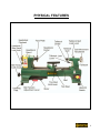
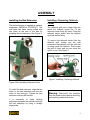
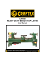
CT160 HEAVY DUTY BENCH TOP LATHE User Manual INDEX General Safety Instructions ....................................................................... Specific Safety Instructions ...................................................................... Heavy Duty Bench Top Lathe Features..................................................... Physical Features ...................................................................................... 3 4 5 6 Setup ......................................................................................................... 7 Un-packing ............................................................................................... 7 Assembly................................................................................................... 8 Adjusting Machine Level............................................................................ 8 Installing the Tool Rest .............................................................................. .8 Installing the Bed Extension ...................................................................... .9 Installing/Removing Tailstock Center ........................................................ .9 Installing/Removing Faceplate .................................................................. 10 Installing/Removing Headstock Center...................................................... 10 Test Run.................................................................................................... 11 Operations and Adjustments ..................................................................... 12 Power Switch............................................................................................. 12 Changing Spindle Speed........................................................................... 12 Tailstock .................................................................................................... 14 Faceplate................................................................................................... 15 Checking Alignment between the Centers................................................. 15 Maintenance.............................................................................................. 15 Trouble Shooting ........................................................................................16 Parts Breakdown ........................................................................ ................17 Pars List ........................................................................ .....18, 19, 20, 21, 22 Warranty.................................................................................................... .23 2 General Safety Instructions WARNING: Do not attempt to operate the machine until you have read thoroughly and have understood completely all instructions, rules and conditions contained in this manual. Failure to comply can result in accidents involving fire, electric shock, or serious personal injury. Know your machine. For your safety, read the owner’s manual carefully. Learn its applications and limitations, as well as specific potential hazards pertinent to this machine. Make sure all tools are properly grounded. If the tool electrical plug has three prongs, it should be used in a three hole electrical socket. If three prongs or two prongs adapter is used, the adapter plug must be properly grounded. Do not remove or disable the third prong. Keep all the guards in place and in good working order. If a guard must be removed for maintenance or cleaning, make sure it is properly attached before using the machine again. Remove adjusting keys and wrenches. Form a habit of checking to see that the keys and adjusting wrenches are removed from the machine. Keep your work area clean. Cluttered areas and workbenches increase the chance if an accident. Do not use the machine in dangerous environments. Do not use power tools in damp or wet locations or expose them to rain. Keep work areas well illuminated. Keep children away. All visitors should keep a safe distance from the work area. Do not force the machine. It will do the job better and be safe at the operating rate for which it is designed. Do not force the machine or attachments to do a job for which they are not designed. Wear proper apparel. Avoid loose clothing, gloves, neckties, rings, bracelets and jewelry which could get caught in moving parts. Non-slip footwear is recommended. Wear protective hair covering to contain long hair. Always use safety glasses. Also, wear a face or dust mask if the operation area is dusty. Everyday eyeglasses only have impact resistant lenses. They are not safety glasses. 3 CT160-10” Heavy Duty Bench Top Lathe Specific Safety Instructions Like all power tools and machinery, proper safety and attention must be adhered to. There is danger associated with using any tool or machine so pay careful attention each and every time you use your tool. If you are not familiar with the operations of a lathe, you should obtain the advice and/or instructions from a qualified professional. Read this operation manual carefully and understand it before operating the lathe. Always wear a face dust mask if operation creates a lot of sawdust and/or chips. Do not over-reach. Keep proper footing and balance at all times. Always operate the tools in a wellventilated area and provide for proper dust removal. Use a dust collection system whenever possible. Maintain machine in top condition. Keep machine clean for best and safest performance. Follow instructions for lubrication and changing accessories. Disconnect the machine from power source before servicing, when changing accessories and when mounting or remounting motor. To avoid accidental starting, make sure the switch is in the OFF position before plugging in the power cord. Turn OFF then machine before making any adjustments or servicing. Do not attempt to measure the workpiece size while the machine is running. Make sure the work-piece is clamped securely between the centers before starting the machine. Only use correct size centers. Never leave the machine running and unattended. Turn the power OFF. Do not leave the machine until it comes to a complete stop. After adjusting or servicing the machine, remember to remove all wrenches or other tools from the machine. Start and stop the machine yourself. Do not have anybody help you do this. Do not use any power tools while under the effects of drugs, alcohol or any medication. IMPORTANT: The safety instructions given above can not be complete because the environment in every shop is different. Always consider safety first as it applies to your individual working conditions. 4 Heavy Duty Bench Top Lathe FEATURES MODEL CT160-HEAVY DUTY BENCH TOP LATHE As part of the growing line of Craftex woodworking equipment, we are proud to offer CT160-Heavy Duty Bench Top Lathe. The Craftex name guarantees Craft Excellence. By following the instructions and procedures laid out in this owner’s manual, you will receive years of excellent service and satisfaction. The CT160 is a professional tool and like all power tools, proper care and safety procedures should be adhered to. Main Motor Speed 1720 RPM Swing Over Bed 10”(254mm) Swing Over Tool Rest (Base) 7-1/2”(190mm) Distance Between Center 15 ½” (394mm) Tailstock Travel 3 ¼” (83mm) Spindle Size: 7-51/64” x 1-7/8” Spindle TPI 1” x 8 TPI Spindle Taper MT2 Spindle Center 5”(127mm) Tailstock Taper MT2 Tailstock Center 5”(127mm) Number of Spindle Speeds 6 Spindle Speed Ranges 480, 1270, 1960, 2730, 3327, 4023 RPM Bed Width 8-3/16”(208mm) Faceplate size 3” (76mm) Bed Construction Cast Iron Headstock Construction Cast Cast Iron & Steel Tailstock Construction Cast Cast Iron & Steel Bearings Shielded and Lubricated Approx. Weight 106 lbs. (45 Kg) Single Phase 1/2 HP, 110V, 60 HZ, 3.8Amps 5 PHYSICAL FEATURES 6 SETUP Before starting setting up the machine you need to read and understand this user manual completely. For the protection of your eyes you need to have safety glasses. The unpainted surfaces of the lathe are coated with rust prevention waxy oil and you will want to remove this before you begin assembly. Use a solvent cleaner that will not damage painted surfaces. CT160 weighs approximately 106 lbs. Do not over-exert yourself. For safe moving method use fork truck or get the help of an assistant or friend. Figure-1 Loose parts Unpacking The machine is properly packaged in a carton for safe transportation. When unpacking, carefully inspect the crate and ensure that nothing has been damaged during transit. Open the crate and check that the machine is in a good condition. There is a bag which contains some loose parts of the machine. After the machine has been un-packed, check that all loose parts shown in Figure-1 are present. When setting up your machine, you will want to find an ideal spot where your machine will most likely be positioned most of the time. Consider your complete work environment as well as working comfortable with the lathe before placing your machine in the ideal spot. The figure below shows minimum workplace for the lathe. 1. Tool Rest 2. Tailstock Center (Live Center) 3. Headstock Center (Dead Center) 4. Center Knock-Out Bar 7 ASSEMBLY The lathe should be mounted on a workbench with proper height. The workbench must be rigid and flat enough to support the weight of the lathe. Make sure the lathe is mounted firmly on the workbench, otherwise clatter problems will occur while operation. Installing the Tool Rest Locate the hole on the tool base and thread the lock handle into the hole. See Figure-3 Before you start assembling the machine you need to level the machine using the four leveling feet. Adjusting Machine Leveling Always note that if the lathe is not leveled properly it may cause bed twisting. A slight bed twisting will cause centers to be out of alignment and also inaccurate turning. Level the machine by turning the four leveling screws, located at the four corners of the bed. Loosen the nut by using a wrench before adjusting leveling screw, turn the leveling screw manually until proper leveling is achieved. Tighten the nut after leveling adjustment. Figure-3 Tool rest lock handle installed Now, insert the tool rest and turn the release lever to lock the tool rest. See Figure-4 Figure-4 Tool rest Installed Figure-2 Leveling screw and nut Whenever you want to move the tool rest base, simply untighten the release lever and move tool rest base where you want and tighten back the release lever. 8 ASSEMBLY Installing the Bed Extension The bed extension is supplied as optional equipment (MODEL# CT160EXT). The mini lathe has been factory drilled with two holes at the end of the bed for installing the bed extension. See Figure-5 Installing / Removing Tailstock Center The tailstock quill has a taper hole into which the tailstock center fits. Fit the tailstock center firmly by hand. Clean the tailstock center shank and the tailstock quill hole before fitting. To remove the tailstock center from the tailstock quill, simply turn the quill movement hand-wheel until the quill end is nearly inside the tailstock. Then loosen the quill fix lever and you can move the quill in or out. See Figure-7 Figure-7 Installing / Removing tailstock Figure-5 Bed Installing Extension Holes To install the bed extension, align the two holes on the bed extension with the two holes on the bed end. Tighten the bed extension with two M8 screws. Warning: Disconnect the machine from the power source before mounting and removing headstock center. It is necessary to make leveling adjustment between the maintain bed and the bed extension by using a straight edge guide. 9 ASSEMBLY Installing / Removing Faceplate First, disconnect the machine from the power source and remove the headstock center. Attach the faceplate to the headstock spindle with the help of threads on it. Now, use knock-out bar and tighten the faceplate as shown in the in Figure-8 Installing / Removing Headstock Center The headstock spindle is designed with a taper hole into which the headstock center fits. Fit the headstock center firmly by hand. Clean the headstock center shank and spindle hole before fitting. Removing the headstock center is done by simply knocking it out, using the supplied knock-out bar. When knocking out the center, hold it by hand to prevent it dropping down. See Figure-9 Figure-8 Installing the faceplate When you want to remove the faceplate, simply do the above procedure in reverse. Figure-9 Knocking out the headstock with the help of knock-out bar Warning: Disconnect the machine from the power source before mounting and removing parts. 10 TEST RUN Once you have assembled your machine completely, it is time for a test run to make sure that the machine works properly and is ready for operation. Connect your machine to the correct power source and turn the power switch ON. Take a careful look in and around your machine before turning it on to ensure everything is in place, all screws and knobs are securely fastened and all controls are working properly. During the test run the machine should run smoothly and create very little noise or vibration. If there is an unusual noise coming from the machine or the machine vibrates a lot, turn the machine OFF right away and inspect the problem. IMPORTANT Before a test run make sure that you have read and understood the manual and you are familiar with the functions and safety features on this machine. IMPORTANT Do not make any adjustments when the machine is running. Failure to follow this warning can cause a serious personal injury. Before turning the machine on, make sure you are wearing your safety glasses and anyone around you is also wearing safety glasses. 11 OPERATIONS & ADJUSTMENTS Power Switch (ON / OFF) Changing the Spindle Speed This lathe is equipped with a rocker type paddle switch to start and stop the lathe, located at the front side of the bed. The switch has a removable locking key to prevent unauthorized operation. If the lathe is not in use for long time, remove the locking key by pulling it put out and store it in a safe place. The CT160 Heavy Duty Bench Top Lathe features 6 spindle speed changes: 500, 1270, 1960, 2730, 23320 and 4020 rpm. The turning speed of the lathe is varied with the work-piece diameter to be turned. When turning a smaller diameter of workpiece, a higher spindle speed is recommended. However, proper selection of spindle speed for the work-piece is made by the operator’s experience. To start the lathe, insert the locking key and shift the switch to the left. To stop the lathe, shift the switch to the right. See Figure-10 Figure-10 Power Switch (ON / OFF) Figure-11 CT160 Heavy Duty Spindle Speed Changes 12 OPERATIONS & ADJUSTMENTS Change spindle speed according to the following procedures: 4. Release the V-belt tension by shifting the belt tension fix lever, located under the bed. 1. Turn OFF the power switch (key switch), and remove the key to avoid unauthorized starting of the lathe. 2. Open the V-belt guard located in the headstock. Loosen the guard lock lever. Figure-13 Adjusting the V-belt tension 5. Place the V-belt to a new position on the pulley. At the same time, turn the headstock fly wheel to facilitate changing of the belt position. Figure-12 Removing the V-belt guard 3. Loosen the belt tension lock knob before shifting the belt tension adjustment lever and tighten it securely after adjustment. Figure-14 V-belt tension changed 6. Make sure the V-belt tension is properly installed in case its position has been changed. 7. Reverse above procedures to return the lathe to its original condition. 13 OPERATIONS & ADJUSTMENTS Adjusting Carriage and Tool Rest Tailstock The carriage can be moved along the bed slide-ways. Loosen the carriage fix lever before adjusting the carriage position. Tighten the fix lever securely after adjustment. The tailstock is used to support the other end of the work-piece to be turned on the lathe. The tailstock can be moved along the bed slide ways. Before moving the tailstock, loosen the tailstock lock lever. Move the tailstock by hand to a desired position, and then tighten the tailstock fix lever securely. The tool rest should be adjusted so that its top is 3/16” (suggested below) above the centers. Loosen the tool rest lock lever before adjusting tool rest position. Tighten the lock lever securely after adjustment. Note: Lubricate the bed slide-ways before moving the tailstock. Figure-15 Adjusting Carriage & Tool Rest on the Bed Figure-16 Tailstock and its components Moving Tailstock Quill In and Out The tailstock quill can be moved in and out of the tailstock casting by turning the tailstock quill movement hand-wheel. Loosen the quill lock lever before turning the hand-wheel. Tighten it securely after the quill has been moved to a proper position. 14 OPERATIONS & ADJUSTMENTS Faceplate This lathe is furnished with a face plate in case the work-piece to be turned and can not be clamped between the headstock center and the tailstock center. The faceplate has been drilled with four holes for clamping the work-piece. Figure-18 Headstock and tailstock centers aligned MAINTENANCE Figure-17 Showing faceplate attached to the lathe To install the faceplate to the headstock please see Page-10. Checking Alignment between the Centers The center alignment has been adjusted properly in the factory before the machine is shipped to you. However, after lengthy operation, the centers may be out of alignment. At this time center alignment needs to be done. To do this, loosen the four screws that tighten the headstock to the bed. Slightly adjust the headstock position to adjust center alignment. See Figure-18 1. Everyday after use, remove chips from the machine and clean it. Apply oil on the sliding surfaces. 2. Everyday after use, turn OFF the power switch and remove the switch key. 3. A build up of dust in the motor can cause motor damage. Periodic cleaning of the motor is not only recommended, but mandatory for normal wood lathe performance. Warning: Disconnect the machine from the power source before mounting, removing or making any adjustments. 15 TROUBLESHOOTING PROBLEM CUTTING TOOL VIBRATION POOR MACHINE ACCURACY CAUSES CORRECTION 1. Work-piece is not clamped firmly. 1. Clamp it firmly. 1. Work-piece is clamped incorrectly. 1. Check balance. 2. Tailstock center and headstock center is out of alignment. 2. Adjust center Alignment. 3. Check machine leveling periodically. 3. Machine leveling loss. MOTOR DOES NOT RUN WHEN POWER WITCH IS TURNED ON MOTOR DOES NOT RUN AT A FULL SPEED MOTOR DOES NOT REACH FULL SPEED 1. Switch is burnt out. 1. Replace the switch. 2. Connection wire is loose or damaged. 2. Tighten or replace wire. 1. Power voltage is too low. 1. Test voltage. 2. Motor is damaged. 2. Check and repair motor. 1. Incorrect power wiring. 1. Replace with correctly sized power wiring. 2. Overloaded. 2. Reduce load. MOTOR OVERHEATING 1. Motor is dirty. 1. Clean motor. 2. Motor is damaged. 2. Check and repair motor. 16 CT160- HEAVY DUTY BENCH TOP LATHE PARTS BREAKDOWN 17 CT160- HEAVY DUTY BENCH TOP LATHE PARTS LIST 18 CT160- HEAVY DUTY BENCH TOP LATHE PARTS LIST 19 CT160- HEAVY DUTY BENCH TOP LATHE PARTS LIST 20 CT160- HEAVY DUTY BENCH TOP LATHE PARTS LIST 21 CT160- HEAVY DUTY BENCH TOP LATHE PARTS LIST 22 WARRANTY CRAFTEX 2 YEARS LIMITED WARRANTY Craftex warrants every product to be free from defects in materials and agrees to correct such defects where applicable. This warranty covers Two Years for parts and 90 days for labour (unless specified otherwise), to the original purchaser from the date of purchase but does not apply to malfunctions arising directly or indirectly from misuse, abuse, improper installation or assembly, negligence, accidents, repairs or alterations or lack of maintenance. Proof of purchase is necessary. All warranty claims are subject to inspection of such products or part thereof and Craftex reserves the right to inspect any returned item before a refund or replacement may be issued. This warranty shall not apply to consumable products such as blades, bits, belts, cutters, chisels, punches etceteras. Craftex shall in no event be liable for injuries, accidental or otherwise, death to persons or damage to property or for incidental contingent, special or consequential damages arising from the use of our products. RETURNS, REPAIRS AND REPLACEMENTS To return, repair, or replace a Craftex product, you must visit the appropriate Busy Bee Tools showroom or call 1-800-461-BUSY. Craftex is a brand of equipment that is exclusive to Busy Bee Tools. For replacement parts directly from Busy Bee Tools, for this machine, please call 1-800-461-BUSY (2879), and have your credit card and part number handy. All returned merchandise will be subject to a minimum charge of 15% for re-stocking and handling with the following qualifications. Returns must be pre-authorized by us in writing. We do not accept collect shipments. Items returned for warranty purposes must be insured and shipped pre-paid to the nearest warehouse Returns must be accompanied with a copy of your original invoice as proof of purchase. Returns must be in an un-used condition and shipped in their original packaging a letter explaining your reason for the return. Incurred shipping and handling charges are not refundable. Busy Bee will repair or replace the item at our discretion and subject to our inspection. Repaired or replaced items will be returned to you pre-paid by our choice of carriers. Busy Bee reserves the right to refuse reimbursement or repairs or replacement if a third party without our prior authorization has carried out repairs to the item. Repairs made by Busy Bee are warranted for 30 days on parts and labour. Any unforeseen repair charges will be reported to you for acceptance prior to making the repairs. The Busy Bee Parts & Service Departments are fully equipped to do repairs on all products purchased from us with the exception of some products that require the return to their authorized repair depots. A Busy Bee representative will provide you with the necessary information to have this done. For faster service it is advisable to contact the nearest Busy Bee location for parts availability prior to bringing your product in for repair. 23