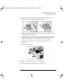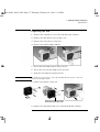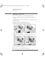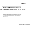
1
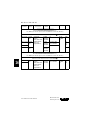
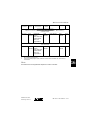
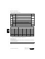
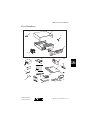
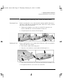
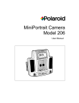
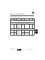
16
HP Vectra VLi 8SF PC
Models and Accessories
Product
Number
Hard
Drive
Video
Controller
Std.
RAM
Multi-media
LAN
OS1
Vectra VLi 8SF PC
Models with Intel Celeron Processor, PPGA2 package,
66 MHz System Bus Speed, and 128 KB Level 2 Cache Memory
HP Vectra VLi 8SF PC 366/66 (CPL: 04/99 )
D7826A/T 4.3 GB
IDE
Integrated
Matrox
MGA-G200 AGP
(8 MB SGRAM
fitted, not
upgradeable)
32 MB
SDRAM
100 MHz
no
3COM
3C905BTX
W95
3COM
3C905BTX
W95
HP Vectra VLi 8SF PC 400/66 (CPL: 04/99 )
D7836A/T 4.3 GB
IDE
D7837A/T 8.4 GB
IDE
Medium-Profile
Desktop Vectras
Integrated
Matrox
MGA-G200 AGP
(8 MB SGRAM
fitted, not
upgradeable)
32 MB
SDRAM
100 MHz
no
64 MB
SDRAM
100 MHz
24 ✕ Max IDE
slim CD-ROM
HP Vectra VLi 8SF PC 16-1
16
HP Vectra VLi 8SF PC
Product
Number
Hard
Drive
Video
Controller
Std.
RAM
Multi-media
LAN
OS1
Vectra VLi 8SF PC
Models with Intel Pentium II Processor,
100 MHz System Bus Speed, and 512 KB Level 2 Cache Memory
HP Vectra VLi 8SF PC 400/100 (CPL: 04/99 )
D7846A/T 4.3 GB
IDE
D7847N/T 8.4 GB
IDE
Integrated
Matrox
MGA-G200 AGP
(8 MB SGRAM
fitted, not
upgradeable)
D7848N
D7860A
4.3 GB
IDE
32 MB
SDRAM
100 MHz
no
64 MB
SDRAM
100 MHz
24 ✕ Max IDE
slim CD-ROM
3COM
3C905BTX
W95
NT
4.0
WS
no
DOS
32 MB
SDRAM
100 MHz
Vectra VLi 8SF PC
Models with Intel Pentium III Processor,
100 MHz System Bus Speed, and 512 KB Level 2 Cache Memory
HP Vectra VLi 8SF PC 450/100 (CPL: 06/99 )
16
D7857N/T 8.4 GB
IDE
D7858N
Integrated
Matrox
MGA-G200 AGP
(8 MB SGRAM
fitted, not
upgradeable)
16-2 HP Vectra VLi 8SF PC
64 MB
SDRAM
100 MHz
24 ✕ Max IDE
slim CD-ROM
3COM
3C905BTX
Medium-Profile
Desktop Vectras
NT
4.0
WS
HP Vectra VLi 8SF PC
Product
Number
Hard
Drive
Video
Controller
Std.
RAM
Multi-media
LAN
OS1
Vectra VLi 8SF PC
Models3 with Intel Celeron User Defined Processor, Main Memory,
and Hard Disk
D7700E
User
defined
Integrated
Matrox
MGA-G200 AGP
(8 MB SGRAM
fitted, not
upgradeable)
User
defined
User defined
User
defined
None
Models3 with Intel Pentium User Defined Processor, Main Memory,
and Hard Disk
D7850E
1.
2.
3.
User
defined
Integrated
Matrox
MGA-G200 AGP
(8 MB SGRAM
fitted, not
upgradeable)
User
defined
User defined
User
defined
None
Operating system preloaded on these models, as indicated in the table.
PPGA=Plastic Pin Grid Array.
Channel Assembly Program (CAP) models: Processor model, hard disk size, and memory is
user defined.
Note
All model have an integrated full-duplex PCI audio controller.
Medium-Profile
Desktop Vectras
HP Vectra VLi 8SF PC 16-3
16
HP Vectra VLi 8SF PC
Supported Accessories
32-MB kit 32-bit SDRAM, 100 MHz non-ECC main memory module
D6501A/T
32-MB kit 32-bit SDRAM, 100 MHz non-ECC main memory module
(pack of 20)
D6504A/T
64-MB kit 32-bit SDRAM, 100 MHz non-ECC main memory module
D6502A/T
64-MB kit 32-bit SDRAM, 100 MHz non-ECC main memory module
(pack of 20)
D6505A/T
128-MB, 32-bit SDRAM, 100 MHz non-ECC main memory module
D6503A/T
256-MB, 32-bit SDRAM, 100 MHz ECC main memory module
D6743A/T
Documentation
User’s Guide Manual Kit
D7820A
Input Devices
HP Standard Keyboard
C4735A
HP Scrolling Mouse
C4736A
Video Displays
All current HP Displays (see the HP Vectra Accessory Service Handbook)
16
Mass Storage
4.3-GB IDE hard disk
D8371A
6.4-GB IDE hard disk
D8372A
8.4-GB IDE hard disk
D8373A
HP 100 MB Atapi II Iomega ZIP drive
D6650A
HP 100 MB Atapi II Iomega ZIP drive (pack of 10)
D6651A
Multimedia
Multimedia sound accessory kit (16-bit audio board, cables, and software) pack of 10
D5183A
24✕ Max IDE slim CD-ROM drive
D8381A
Data Communications and LAN Adapter Boards
HP 56K V90 PCI Fax Modem
D7808A
Security
HP Master Pass Key System Kit
D6655A
HP Master Pass Key
D6658A
16-4 HP Vectra VLi 8SF PC
Medium-Profile
Desktop Vectras
HP Vectra VLi 8SF PC
System Board, BIOS, and Memory
System Board
Switches: See the
table on the next page.
Processor: Pentium II
or Pentium III, SECC2
package, with integrated
heatsink and level-2
cache memory.
Main Memory:
Two DIMM sockets which
support up to a maximum
of 512 MB.
Install 32 MB, 64 MB, 128
MB or 256 MB 100 MHz
SDRAM modules.
Medium-Profile
Desktop Vectras
16
Processor: Celeron
PPGA (Plastic Pin
Grid Array) package
with Zero Insertion
Force (ZIF) socket.
HP Vectra VLi 8SF PC 16-5
HP Vectra VLi 8SF PC
System Board Switches
Switch
1
Off
On
Crash recovery mode: forces booting in the BIOS boot
block area
Off
Off
Normal operation
On
Normal operation (keyboard space-bar power-on
enabled)
Off
Disables keyboard power- on
On
Clears User and Administrator passwords
Off
Normal operation
3
Off
On
Clears CMOS (to reload the Setup program defaults)
Normal operation
6-9
—
Processor frequency, see the following table
—
10
—
RESERVED — Do Not Use
Off
System Frequency1
Bus 100 MHz Bus 66 MHz
MHz2
2332
Off
Switch
6
7
8
9
MHz
Off
On
Off
On
400 MHz
2662 MHz
On
Off
On
On
450 MHz
3002 MHz
Off
Off
On
On
500 MHz
3332 MHz
On
Off
Off
On
350
1.
2.
On
Off
5
16
Default
RESERVED — Do Not Use
2
4
Function
—
2
Reserved
366 MHz
Off
Off
Off
On
Reserved
4002 MHz
On
On
On
Off
Reserved
4332 MHz
Off
On
On
Off
System and processor frequency is automatically determined by the type of processor.
These options are not available in any model of the HP Vectra VLi 8SF at the time of
printing. This information is provided for completeness only.
BIOS History
For the latest BIOS, the flasher utility program, and the BIOS history refer to the
HP World Wide Web site.
http://www.hp.com/go/vectrasupport/
16-6 HP Vectra VLi 8SF PC
Medium-Profile
Desktop Vectras
HP Vectra VLi 8SF PC
Part Numbers
a
f
e
b
c
d
10
2
1
8
15
12
3
9
4
11
13
16
6
5
7
17
14
Medium-Profile
Desktop Vectras
HP Vectra VLi 8SF PC 16-7
16
HP Vectra VLi 8SF PC
Parts List for HP Vectra VLi 8SF PC
Item
1
Description
Chassis assembly:
a
b
c
d
e
f
2
3
4
5
6
7
8
9
10
Top cover assembly
Bezel assembly
Status panel assembly
Airflow guide/fan assembly
Mini NLX board extractor
Master key lock
Power supply
FDD filler kit (RFI plate +filler)
CD-ROM drive bay blank filler
HDD screws/washers and RFI retainer kit
Rear bezel
Stand foot assembly
Backplane board with 3COM 10/100BT
network controller
System board
IDE hard disk drive 1
4.3 GB
8.4 GB
16
11
12
13
14
15
16
17
1.
2.
IDE and FDD cable kit
CD-ROM cable
Flexible disk drive (bezel-less)
24 ✕ Max Slim IDE CD-ROM drive
Enhanced mouse with scroll/zoom wheel
Standard keyboard
Standard keyboard (Japan)
Multimedia keyboard
Battery type CR2032
Headphones
Repl.
Part Number
5064-7404
Exchange
Part Number
—
5064-9103
5064-9104
5064-9151
5064-9108
5064-9739
5064-9111
0950-3432
5064-9131
5042-3098
5064-9109
5064-7500
5064-9105
5064-7406
—
See PC’s system board parts list
—
—
5064-9137
5183-9424
D2035-60391
—
C4736-60101
C4735-603xx2
C4732-60324
C4734-605xx2
1420-0356
5182-3552
D8371-69001
D8373-69001
—
—
—
D4383-69091
—
—
—
—
—
—
For optional disk drive information, see the Accessory Service Handbook.
Where “xx” is the code for your national keyboard (see the Accessory Service Handbook).
16-8 HP Vectra VLi 8SF PC
Medium-Profile
Desktop Vectras
HP Vectra VLi 8SF PC
System Board Parts List for HP Vectra VLi 8SF PC
Description
System board:
Vectra VLi 8SF system board with 370-pin
socket (PGA370) for Intel Celeron processor
Vectra VLi 8SF system board with SC242 slot
connector for Intel Pentium II/III processor
Processors:
Intel Celeron 366/66 128KB L2 cache
Intel Celeron 400/66 128KB L2 cache
Heat-sink for Intel Celeron processor
Thermal Interface material for Intel Celeron
processor
Intel Pentium II 400/100 512KB L2 cache
Intel Pentium III 450/100 512KB L2 cache
Main memory modules:
1 ✕ 32-MB, 100 MHz non-ECC SDRAM
1 ✕ 64-MB, 100 MHz non-ECC SDRAM
Repl.
Part Number
Exchange
Part Number
—
D7812-69001
—
D4066-69001
5064-7495
5064-9130
1205-0932
6040-0939
—
—
—
—
D7945-69001
D7946-69001
D6501-63001
D6502-63001
—
—
Manuals and Documentation for HP Vectra VLi 8SF PC
User’s Guide
Troubleshooting and Upgrade Guide
Technical Reference Manual: hardware and BIOS
1.
D7820A
no number1
no number1
Electronic file available on HP’s Web site.
Notes:
____________________________________________________________________
____________________________________________________________________
____________________________________________________________________
____________________________________________________________________
____________________________________________________________________
____________________________________________________________________
Medium-Profile
Desktop Vectras
HP Vectra VLi 8SF PC 16-9
16
HP Vectra VLi 8SF PC
____________________________________________________________________
____________________________________________________________________
____________________________________________________________________
____________________________________________________________________
____________________________________________________________________
____________________________________________________________________
____________________________________________________________________
____________________________________________________________________
____________________________________________________________________
16
____________________________________________________________________
____________________________________________________________________
____________________________________________________________________
____________________________________________________________________
____________________________________________________________________
____________________________________________________________________
____________________________________________________________________
____________________________________________________________________
16-10 HP Vectra VLi 8SF PC
Medium-Profile
Desktop Vectras
nitro-dt.bk : nitro-3.fb4 Page 23 Thursday, February 18, 1999 12:14 PM
3 Replacing Hardware Components
Removing and Replacing the Cover & Front Panel
Removing and Replacing the Cover & Front Panel
Removing the Cover
Before removing the cover, switch off the monitor and PC, disconnect
all power cords and any telecommunication cables. If necessary, unlock
the cover at the rear of the PC.
1 Unfasten the thumb screw at the rear of the PC, open the rear
latches and slide the cover backwards to remove it.
2
Replacing the Cover
If replacing the fan, remove the front panel.
Before replacing the cover, ensure that all internal cables are properly
connected and safely routed.
1 If necessary, replace the front panel.
2 Align the cover with the arrows indicated and replace it.
3 Close the latches on the rear of the PC and fasten the thumb screw.
4 If required, lock the cover at the rear of the PC.
English 23
nitro-dt.bk : nitro-3.fb4 Page 24 Thursday, February 18, 1999 12:14 PM
3 Replacing Hardware Components
Replacing a Memory Module
Replacing a Memory Module
Location of Main Memory — modules
can be installed in either slot
1 Remove the computer’s cover (described in this chapter).
2 Open the two tabs and remove the old memory module.
3 Insert the new memory module (aligning it) and close the two tabs.
4 Replace the cover (described in this chapter).
24 English
nitro-dt.bk : nitro-3.fb4 Page 25 Thursday, February 18, 1999 12:14 PM
3 Replacing Hardware Components
Replacing an Accessory Board
Replacing an Accessory Board
NOTE
Only use XT format ISA accessory boards (width less than 10.4 cm or
4.09 inches).
1 Remove the computer’s cover (described in this chapter).
2 Unfasten the retaining bracket and rotate it open.
3 Hold the old board firmly and carefully pull it out.
4 Aligning the new board carefully, slide it into position and press it
firmly into the slot.
5 Rotate the retaining bracket closed and fasten it.
6 Replace the cover (described in this chapter).
English 25
nitro-dt.bk : nitro-3.fb4 Page 26 Thursday, February 18, 1999 12:14 PM
3 Replacing Hardware Components
Which Drive Connectors to Use
Which Drive Connectors to Use
Internal drives, such as hard disk drives, DVD drives, or CD-ROM
drives, must be connected to data and/or power cables. When replacing
these drives, ensure you use the correct data and power connectors.
CD-ROM drive
Hard disk drive
Floppy drive
Power Connectors
Number in Desktop
Use for
1
Hard disk drive
1
Floppy disk drive
Replacing the Hard Disk Drive
For information on recovering the contents of your hard disk drive,
refer to the Troubleshooting and Upgrade Guide, available on HP’s
web site www.hp.com/go/vectrasupport.
1 Remove the computer’s cover (described in this chapter).
26 English
nitro-dt.bk : nitro-3.fb4 Page 27 Thursday, February 18, 1999 12:14 PM
3 Replacing Hardware Components
Replacing the Hard Disk Drive
2 Remove all drive connectors.
Floppy drive
Hard drive
Main power
3 Press the retaining clip on top of the drive tray and slide it backwards
to remove it.
4 Unfasten the screws on the bottom of the drive tray and remove the
hard disk drive.
4
3
CAUTION
Take care when handling the hard disk drive during installation. A one-quarter
inch drop can damage it.
5 Slide the new hard drive into the drive tray (with correct
orientation) and fasten the screws.
6 Replace the drive tray.
5
6
7 Attach all data and power connectors.
8 Replace the cover (described in this chapter).
English 27
nitro-dt.bk : nitro-3.fb4 Page 28 Thursday, February 18, 1999 12:14 PM
3 Replacing Hardware Components
Replacing the Slim CD-ROM Drive
Replacing the Slim CD-ROM Drive
WARNING
To avoid electrical shock and harm to your eyes by laser, do not open the laser
module. The laser module should be serviced by service personnel only. Do
not attempt to make any adjustment to the laser unit. Refer to the label on the
CD-ROM for power requirements and wavelength. This product is a class 1
laser product.
1 Remove the computer’s cover (described in this chapter).
2 Remove the drive’s connector.
3 Press the retaining clip on top of the drive tray and slide it backwards
to remove it.
4 Unlatch the CD-ROM drive to remove it from the drive tray.
28 English
nitro-dt.bk : nitro-3.fb4 Page 29 Thursday, February 18, 1999 12:14 PM
3 Replacing Hardware Components
Replacing the Slim CD-ROM Drive
5 Align the new CD-ROM drive with the arrows indicated on the drive
tray and clip it into position.
6 Replace the drive tray.
7 Attach drive’s connector.
8 Replace the cover (described in this chapter).
English 29
nitro-dt.bk : nitro-3.fb4 Page 30 Thursday, February 18, 1999 12:14 PM
3 Replacing Hardware Components
Replacing the Floppy Drive
Replacing the Floppy Drive
1 Remove the computer’s cover (described in this chapter).
2 Remove all drive connectors.
Hard drive
Floppy drive
Main power
3 Press the retaining clip on top of the drive tray and slide it backwards
to remove it.
4 Unfasten the screws on the sides of the drive tray and remove the
floppy drive.
5 Slide the new floppy drive into the drive tray (with correct
orientation) and fasten the screws.
6 Replace the drive tray.
7 Attach all data and power connectors.
8 Replace the cover (described in this chapter).
30 English
nitro-dt.bk : nitro-3.fb4 Page 31 Thursday, February 18, 1999 12:14 PM
3 Replacing Hardware Components
Replacing the Processor
Replacing the Processor
1 Remove the computer’s cover (described in this chapter).
2 Remove the old processor.
Removing a
Celeron processor
Removing a
Pentium processor
3 Install the new processor and clip it into place.
Replacing a
Celeron processor
Replacing a
Pentium processor
4 If the new processor is a different speed, ensure that the system
board switches are correctly set for your processor speed. (The
correct switch settings are indicated on the system board.)
For Celeron processors, the processor’s speed settings are
automatic.
5 Ensure that the latest BIOS version is flashed.
6 Replace the cover (described in this chapter).
English 31
nitro-dt.bk : nitro-3.fb4 Page 32 Thursday, February 18, 1999 12:14 PM
3 Replacing Hardware Components
Replacing the System Board
Replacing the System Board
1 Remove the computer’s cover (described in this chapter).
2 Remove the side panel.
3 Remove the main memory and processor from the old system board
(described in this chapter).
4 Remove the old system board.
5 Carefully slide in the new system board, aligning the rails correctly.
32 English
nitro-dt.bk : nitro-3.fb4 Page 33 Thursday, February 18, 1999 12:14 PM
3 Replacing Hardware Components
Replacing the System Board
6 Push the system board into place using the lever. Ensure the
connectors are well aligned and fully engaged.
7 Replace the main memory and processor in the new system board
(described in this chapter).
8 If the new processor is a different speed, ensure that the system
board switches are correctly set for your processor speed. (The
correct switch settings are indicated on the system board.)
For Celeron processors, the processor’s speed settings are
automatic.
9 Replace the side panel.
10 Replace the cover (described in this chapter).
11 Ensure that the latest BIOS version is flashed.
English 33
nitro-dt.bk : nitro-3.fb4 Page 34 Thursday, February 18, 1999 12:14 PM
3 Replacing Hardware Components
Replacing the Power Supply
Replacing the Power Supply
WARNING
To avoid electrical shock, do not open the power supply. There are no userserviceable parts inside.
1 Remove the computer’s cover (described in this chapter).
2 Remove all internal power supply connectors.
Hard drive
Floppy drive
Main power
3 Remove the screws securing the power supply.
Remove the three external
screws and the internal
screw
4 Slide the power supply back and remove it.
5 Insert the new power supply.
6 Replace the three screws to secure the power supply.
7 Reconnect all internal power supply connectors.
8 Replace the cover (described in this chapter).
9 Select the correct voltage setting for your country.
34 English
nitro-dt.bk : nitro-3.fb4 Page 35 Thursday, February 18, 1999 12:14 PM
3 Replacing Hardware Components
Replacing the Fan
Replacing the Fan
1 Remove the computer’s cover (described in this chapter).
2 Remove the side panel (refer to page 32).
3 Remove the fan’s power connector.
4 Remove the airflow guide and fan.
5 Attach the four rubber pins to the new fan.
6 Attach the new air flow guide to the new fan.
7 Align the fan and insert it into the PC.
CAUTION
To ensure the fan operates correctly, install it with the power connector
in the bottom right corner.
8 Connect the power connector.
Ensure fan is installed with power
connector in bottom right corner
9 Replace the side panel and cover (described in this chapter).
English 35
nitro-dt.bk : nitro-3.fb4 Page 36 Thursday, February 18, 1999 12:14 PM
3 Replacing Hardware Components
Replacing the Riser Card
Replacing the Riser Card
1 Remove the computer’s cover (described in this chapter).
2 Remove the side panel and the system board (described in this
chapter).
3 Remove any connectors attached to the riser card and any accessory
boards installed.
4 Remove the screw securing the riser card.
5 Slide the riser card forward and tilt to remove it.
4
5
6 Insert the new riser card.
7 Slide the riser card back into position and replace the screw to
secure it.
6
7
8 Replace the system board, side panel and any accessory boards.
9 Reconnect all device connectors.
10 Replace the cover (described in this chapter).
36 English