1
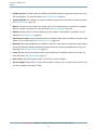
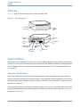
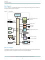
Mac mini Developer
Note
(Legacy)
Contents
Introduction to Mac mini Developer Note 6
Organization of This Document 6
Overview to the Mac mini 7
Features 7
Enclosure 9
System Software 9
Computer Identification 9
NMI without Programmer’s Switch 10
Velocity Engine Acceleration 11
Architecture 12
Block Diagram and Buses 12
Block Diagram 13
Main ICs and Buses 13
Microprocessor and Cache 14
PowerPC G4 Microprocessor 14
Level 2 Cache 14
Memory and I/O Device Controller 14
System RAM 15
Video Display Subsystem 15
Boot ROM 16
Ethernet Controller 16
FireWire 400 Controller 16
Ultra ATA/100 Interface 16
Modem Support 17
Bluetooth Technology 17
Power Controller 17
Sound Circuitry 17
AirPort Extreme Wireless Support 18
USB Interface 18
Devices and Ports 19
USB Ports 19
Retired Document | 2005-04-05 | Copyright © 2005 Apple Computer, Inc. All Rights Reserved.
2
Contents
USB Connectors 19
USB Features 20
FireWire 400 Port 21
FireWire Device Programming 21
FireWire 400 Connector 22
Target Disk Mode 23
Ethernet Port 24
Internal Modem 24
AirPort Extreme Card 25
Data Security 25
AirPort Extreme Hardware 26
AirPort Extreme Software 26
Bluetooth Technology 26
Hard Disk Drive 27
Combo Drive 27
SuperDrive 28
DVI Port 29
DVI to Video Adapter 30
Sound System 31
Sound Input 32
Sound Output 32
Audio CODEC 33
RAM Expansion 34
RAM Expansion 34
RAM Expansion Modules 34
Mechanical Design of RAM DIMMs 34
Electrical Design of RAM DIMMs 35
Supplemental Reference Documents 36
Apple Technical Notes 36
3D Graphics 36
PowerPC G4 Microprocessor 36
Velocity Engine (AltiVec) 37
Mac OS X 37
I/O Kit 37
Open Firmware 37
RAM Expansion Modules 38
ATA Devices 38
USB Interface 39
Retired Document | 2005-04-05 | Copyright © 2005 Apple Computer, Inc. All Rights Reserved.
3
Contents
Ethernet 39
FireWire Interface 39
Digital Visual Interface 40
Wireless Networks 40
Bluetooth 40
Abbreviations 41
Index 46
Retired Document | 2005-04-05 | Copyright © 2005 Apple Computer, Inc. All Rights Reserved.
4
Figures and Tables
Overview to the Mac mini 7
Figure 1-1
Mac mini Enclosure 9
Architecture 12
Figure 2-1
Table 2-1
Block diagram 13
Bus speeds 15
Devices and Ports 19
Figure 3-1
Figure 3-2
Figure 3-3
Figure 3-4
Table 3-1
Table 3-2
Table 3-3
Table 3-4
Table 3-5
Table 3-6
Table 3-7
Table 3-8
USB Type A port and pins 19
FireWire 400 connector 22
DVI connector 29
S-video connector 30
Signals on the USB port 19
Signals on the FireWire 400 connector 22
Signals on the Ethernet connector 24
Types of media read and written by the Combo drive 27
Types of media read and written by the SuperDrive 28
Signals on the DVI connector 29
Pin assignments for the S-video output connector 30
Desktop sizes for S-video output 31
RAM Expansion 34
Table 4-1
Sizes of DDR SDRAM expansion DIMMS and devices 35
Retired Document | 2005-04-05 | Copyright © 2005 Apple Computer, Inc. All Rights Reserved.
5
Introduction to Mac mini Developer Note
Important: This document may not represent best practices for current development. Links to downloads
and other resources may no longer be valid.
This developer note gives a technical description of the Mac mini. The note provides information about the
computer’s internal design, input-output features, and expansion capabilities.
This developer note is intended to help hardware and software developers design products that are compatible
with the products described here. If you are not already familiar with Macintosh computers or if you would
simply like additional technical information, refer to Appendix A, Supplemental Reference Documents, (page
36) for details
Organization of This Document
The information in this note is arranged in four chapters and two appendixes.
●
Chapter 1, Overview to the Mac mini, (page 7) introduces the Mac mini, describes its features, and
mentions a few software issues of interest to developers.
●
Chapter 2, Architecture, (page 12) describes the internal organization of the computer. It includes a
functional block diagram and descriptions of the main components on the logic board.
●
Chapter 3, Devices and Ports, (page 19) describes the I/O ports and the built-in I/O devices.
●
Chapter 4, RAM Expansion, (page 34) includes development guidelines for the RAM expansion modules.
●
Appendix A, Supplemental Reference Documents, (page 36) provides sources of additional information
about the technologies used in the Mac mini.
●
Appendix B, Abbreviations, (page 41) lists standard units of measure and other abbreviations used in this
developer note.
Retired Document | 2005-04-05 | Copyright © 2005 Apple Computer, Inc. All Rights Reserved.
6
Overview to the Mac mini
This chapter lists the features of the new Mac mini and provides information about a few software issues of
interest to developers. The Mac mini does not ship with a monitor, keyboard, or mouse.
Features
●
Microprocessor: The Mac mini has a PowerPC G4 microprocessor running at a clock speed of 1.25 GHz or
1.42 GHz. For more information, see PowerPC G4 Microprocessor (page 14).
●
Memory: The computer comes with 256 MB of DDR333 (PC2700) SDRAM installed in an internal 184-pin
DIMM expansion slot, with build-to-order options of 512 MB and 1 GB. The maximum supported memory
is 1 GB. For more information, see RAM Expansion Modules (page 34).
●
Graphics: The video circuits provide built-in 2D and 3D acceleration using an ATI Radeon 9200 graphics
processor with 32 MB 190 MHz DDR memory. For more information, see Video Display Subsystem (page
15).
●
Main memory bus: The speed of the memory bus is 167 MHz. For more information, see Main ICs and
Buses (page 13).
●
Cache: The 512 KB on-chip L2 cache is included on the microprocessor IC and has the same clock speed
as the microprocessor. For more information, see Level 2 Cache (page 14).
●
Hard disk storage: The built-in hard disk drive has a capacity of 40 GB or 80 GB, with an 80 GB build-to-order
option. For more information, see Hard Disk Drive (page 27).
●
Combo drive: The Mac mini has a combination DVD-ROM/CD-RW drive. For more information, see Combo
Drive (page 27).
●
SuperDrive : A SuperDrive (CD-RW/DVD-R) is available as a build-to-order option. For more information,
see SuperDrive (page 28).
●
External video monitor: The Mac mini has a DVI port and includes a DVI to VGA adapter. A video adapter
with composite and S-video connectors is available separately. For more information, see DVI to Video
Adapter (page 30).
●
Video RAM: The video hardware includes 32 MB of DDR video memory, which supports 3D features and
millions of colors in all resolutions. For more information, see Video Display Subsystem (page 15) and DVI
Port (page 29).
●
USB ports: The Mac mini has two USB 2.0 ports. For more information, see USB Ports (page 19).
Retired Document | 2005-04-05 | Copyright © 2005 Apple Computer, Inc. All Rights Reserved.
7
Overview to the Mac mini
Features
●
FireWire 400 ports: The Mac mini has one IEEE-1394a FireWire 400 port supporting transfer rates of 100,
200, and 400 Mbps. For more information, see FireWire 400 Port (page 21).
●
Target Disk Mode: The computer can act like a FireWire storage device connected to another computer.
See Target Disk Mode (page 23).
●
Modem: The Mac mini has a built-in fax modem with a V.92 56 Kbps data rate; an optional to configure
without a modem is available. For more information, see Internal Modem (page 24).
●
Ethernet: The Mac mini has a built-in Ethernet port for a 10Base-T and 100Base-T operation. For more
information, see Ethernet Port (page 24).
●
AirPort Extreme Card: An internal AirPort Extreme Card wireless LAN module is available as a build-to-order
option. For more information, see AirPort Extreme Card (page 25).
●
Bluetooth: Fully-integrated Bluetooth is available as a build-to-order option to enable short-range wireless
connections between desktop and laptop computers and a host of other peripheral devices. For more
information, see Bluetooth Technology (page 17).
●
Sound: The Mac mini has an internal speaker with amplifier and a headphone/audio line-out jack. For
more information, see Sound System (page 31).
●
Power source: The primary power source is an 85 W, 18.5 V power adapter.
●
Size and weight: The Mac mini is 2 inches (5.08 cm) high, 6.5 inches (16.51 cm) wide, and 6.5 inches (16.51
cm) deep; it weighs 2.9 pounds (1.32 kg).
Retired Document | 2005-04-05 | Copyright © 2005 Apple Computer, Inc. All Rights Reserved.
8
Overview to the Mac mini
Enclosure
Enclosure
Figure 1-1 (page 9) shows the front and rear views of the Mac mini.
Figure 1-1
Mac mini Enclosure
Slot-loading
optical drive
Power
indicator
light
Power
button
Security
slot
Power
port
Headphone
port
Ethernet port
(10/100Base-T)
Video out
port
Modem port
(optional)
FireWire
port
USB ports (2)
System Software
The Mac mini comes with Mac OS X version 10.3.7 or later installed as the default system. Mac OS 9 applications
can be run in Classic mode. Install the Classic environment from the “Additional Hardware and Apple Software
Test” CD shipped with your computer. For more information about Mac OS X, see the reference listed in Mac
OS X (page 37).
Computer Identification
Rather than reading the box flag or the model string and then making assumptions about the computer’s
features, applications that need to find out the features of the computer should use IORegistry calls to test for
the features they require. IORegistry calls are part of the I/O Kit API. For more information, see the references
listed at I/O Kit (page 37).
Asset management software that reports the kind of computer it is run on can obtain the value of the model
property from the IOService plane of the IORegistry. For the Mac mini, the value of the string in the compatible
property is PowerMac10,1.
Retired Document | 2005-04-05 | Copyright © 2005 Apple Computer, Inc. All Rights Reserved.
9
Overview to the Mac mini
System Software
NMI without Programmer’s Switch
Current Macintosh computers do not have a programmer’s switch, which allowed users to generate a
non-maskable interrupt (NMI). The paragraphs below describe how to generate an NMI from a remote session
for systems that do not have a physical programmer's switch.
Starting with Mac OS X 10.1.2, the OS will promote and recognize the DB_NMI bit in the debug parameter of
the “boot-args” property from Open Firmware. When the DB_NMI bit is set, the user can generate a non-maskable
interrupt (NMI) by pressing the system's power button. This replaces the power button’s sleep or wake response.
The system reads the state of the bit at boot time from the boot-args configuration variable. For more
information about the debug flags, please see Inside Mac OS X: Kernel Programming .
To set the DB_NMI bit, enter the following command at the Terminal to display the current debug flag settings.
% nvram boot-args
Add the parameter debug=0x4, as follows.
% sudo nvram boot-args="<current settings> debug=0x4"
After the DB_NMI bit in the debug parameter is set, reboot the machine. After reboot, pressing the power
button for approximately 1 second will generate an NMI.
Note: If the power button is pressed for more than five seconds, the system will immediately power
off.
The power button will retain this functionality until Mac OS X is restarted without the DB_NMI bit set. To clear
this bit, issue the nvram command omitting debug=0x4 parameter, as follows, then restart the machine.
% sudo nvram boot-args=""
Retired Document | 2005-04-05 | Copyright © 2005 Apple Computer, Inc. All Rights Reserved.
10
Overview to the Mac mini
System Software
Note: The debug flags bit will be cleared if you use System Preferences to change the startup disk.
It may also be cleared if you perform an installation that requires a restart.
Velocity Engine Acceleration
The Velocity Engine (an implementation of AltiVec) is the vector processing unit in the PowerPC G4
microprocessor. Some system software has been modified to take advantage of the accelerated processing
that the Velocity Engine makes possible. System software has also been modified to support low-level operations
using the Velocity Engine.
For complete information on the Velocity Engine, refer to the following Apple website:
http://developer.apple.com/hardwaredrivers/ve/index.html
Retired Document | 2005-04-05 | Copyright © 2005 Apple Computer, Inc. All Rights Reserved.
11
Architecture
This chapter describes the architecture of the Mac mini. It includes information about the major components
on the main logic board: the microprocessor, the other main ICs, and the buses that connect them to each
other and to the I/O interfaces.
Block Diagram and Buses
This section is an overview of the major ICs and buses on the computer’s main logic board.
Retired Document | 2005-04-05 | Copyright © 2005 Apple Computer, Inc. All Rights Reserved.
12
Architecture
Block Diagram and Buses
Block Diagram
Figure 2-1 (page 13) is a simplified block diagram of the main logic board. The diagram shows the main ICs
and the buses that connect them together.
Figure 2-1
Block diagram
PowerPC G4
microprocessor
(L2 cache: 512K 1:1)
167 MHz
MaxBus
DDR SDRAM
DIMM slot
Radeon
9200
graphics IC
167 MHz
Memory
bus
Hard disk Device 0
Ultra
drive
ATA/100
bus
Optical
drive
AGP 4X
bus
Device 1
DVI/VGA/composite/S-video
output port
32 MB
DDR RAM
Intrepid
memory
controller
and I/O
device
controller
I2S
FireWire
PHY
FireWire 400 port
Ethernet
PHY
Ethernet port
10/100 Mbps
Audio
codec
Headphone/audio line-out jack
Built-in
speaker
AirPort Extreme
PCI bus
Boot
ROM
I2C
PMU
power controller
PCI USB 2.0
controller
Power
button
USB 2.0 port (480 Mbps)
USB 2.0 port (480 Mbps)
Fan
Bluetooth
12 Mbps
USB
Data pump
and DAA
I2S
Modem port
Modem module
Main ICs and Buses
The architecture of Mac mini is designed around the PowerPC G4 microprocessor and the Intrepid memory
and I/O device controller. The Intrepid occupies the center of the block diagram.
Retired Document | 2005-04-05 | Copyright © 2005 Apple Computer, Inc. All Rights Reserved.
13
Architecture
Microprocessor and Cache
The MaxBus connects the PowerPC G4 microprocessor to the Intrepid ASIC. The MaxBus has 64 data lines, 32
address lines, and a bus clock speed of 167 MHz. The Intrepid ASIC has other buses that connect with the boot
ROM, the hard disk drive, and the optical drive, the power controller IC, the sound IC, the internal modem
module, and the optional wireless LAN module.
The Intrepid I/O controller has a 32-bit PCI bus with a bus clock speed of 33 MHz.
Each of the components listed here is described in one of the following sections.
Microprocessor and Cache
The microprocessor is a 1.25 GHz or 1.42 GHz PowerPC G4 with a built-in level 2 (L2) cache.
PowerPC G4 Microprocessor
The PowerPC G4 microprocessor used in the Mac mini has many powerful features, including.
●
32-bit PowerPC implementation
●
superscalar PowerPC core
●
Velocity Engine (AltiVec technology): 128-bit wide vector execution unit
●
pipelined, high bandwidth system bus, called MaxBus
●
dual 32 KB instruction and data caches (level 1)
●
built-in 512 KB on-chip L2 cache
To find more information, see the reference at PowerPC G4 Microprocessor (page 36).
Level 2 Cache
The data storage for the L2 cache consists of 512 KB of fast static RAM that is built into the microprocessor
chip along with the cache controller. The built-in L2 cache runs at the same clock speed as the microprocessor.
Memory and I/O Device Controller
The Intrepid ASIC combines several functions into a single IC. The IC contains the memory controller, the PCI
bus bridge, the Ethernet and FireWire 400 interfaces, the USB 1.1 interface, and the AGP interface.
Retired Document | 2005-04-05 | Copyright © 2005 Apple Computer, Inc. All Rights Reserved.
14
Architecture
Memory and I/O Device Controller
In addition to the buses listed in Table 2-1 (page 15), the Intrepid ASIC also has separate interfaces to the
physical layer (PHY) ICs for Ethernet and FireWire 400 and an I2C interface that is used for configuring the
memory subsystem.
Table 2-1
Bus speeds
Name of bus
Destinations
Width of data path
Bus clock speed/ data
rate
MaxBus
Microprocessor
64 bits
167 MHz
Memory bus (DDR)
System RAM
64 bits
167 MHz (2x)
AGP 4x bus
Graphics IC
32 bits
66 MHz (4x)
Ultra ATA -100 bus (device 0)
Hard drive
16 bits
100 MBps
Ultra ATA -100 bus (device 1)
Optical drive
16 bits
33 MBps
The Intrepid ASIC provides DB-DMA (descriptor-based direct memory access) support for the I/O channels. The
DBDMA system provides a scatter-gather process based on memory resident data structures that describe the
data transfers. The DMA engine is enhanced to allow bursting of data files for improved performance.
The following sections describe the subsystems that are connected to the Intrepid ASIC.
System RAM
The memory subsystem in the Mac mini consists of 256 MB of DDR333 (PC2700) SDRAM in one of the DIMM
slot. The data bus to the RAM is 64 bits wide, and the memory interface is synchronized to the MaxBus interface
at 167 MHz. The system supports a maximum of 1 GB.
Note: Additional memory can be installed as a build-to-order option or by an Authorized Apple
Service Provider.
For more information on system RAM, see RAM Expansion (page 34).
Video Display Subsystem
The display subsystem consists of a graphics controller IC and 32 MB of DDR on the main logic board. The
graphics controller IC is an ATI Radeon 9200. It contains 2D and 3D acceleration engines, front-end and back-end
scalers, a CRT controller, and an AGP bus interface with bus master capability.
Retired Document | 2005-04-05 | Copyright © 2005 Apple Computer, Inc. All Rights Reserved.
15
Architecture
Memory and I/O Device Controller
The interface between the graphics IC and the rest of the system is a 4x AGP (accelerated graphics port) bus
on the Intrepid IC. To give the graphics IC fast access to system memory, the AGP bus has separate address
and data lines and supports deeply pipelined read and write operations. The AGP bus has 32 data lines and a
clock speed of 66 MHz.
The graphics IC uses a graphics address remapping table (GART) to translate AGP logical addresses into physical
addresses. The graphics driver software can allocate memory in both the dedicated SDRAM and the main
memory.
For information about the display and supported resolutions, see DVI Port (page 29).
Boot ROM
The boot ROM is a 1 M by 8 bit device and is connected to the Intrepid ASIC by way of the high byte of the
PCI bus plus three additional control signals: chip select, write enable, and output enable.
Ethernet Controller
The Mac mini includes an ethernet media access controller (MAC) that implements the Link layer. The Intrepid
ASIC provides DB-DMA support for the Ethernet interface.
The controller is connected by a PCI bus to a PHY interface IC that is capable of operating in either 10-BaseT
or 100-BaseT mode. The actual speed of the link is automatically negotiated by the PHY and the bridge or
router to which it is connected. For information about the port, see Ethernet Port (page 24).
FireWire 400 Controller
The Mac mini includes an IEEE 1394a FireWire 400 controller with a maximum data rate of 400 Mbps (50MBps).
The Intrepid IC provides DMA (direct memory access) support for the FireWire interface. The FireWire 400
controller complies with the Open Host Controller Interface (OHCI) specification.
The controller IC implements the FireWire link layer. A physical layer IC, called a PHY, implements the electrical
signalling protocol of the FireWire interface.
Ultra ATA/100 Interface
The Ultra ATA/100 interface supports the hard disk drive as the master device 0 and the optical drive as the
slave device 1. The Apple System Profiler identifies these devices as device 0 and device 1.
The Ultra ATA/100 interface complies with and supports a subset of industry standard ATA/ATAPI-6 and transfer
protocols up to ultra DMA mode 5. For more information, see Hard Disk Drive (page 27), Combo Drive (page
27) and SuperDrive (page 28).
Retired Document | 2005-04-05 | Copyright © 2005 Apple Computer, Inc. All Rights Reserved.
16
Architecture
Memory and I/O Device Controller
Modem Support
The internal modem is connected to an internal I2S interface. The modem provides digital call progress signals
to the sound circuitry. The analog side of the connection gets power from the phone line; the digital side gets
power from the Mac mini. The modem is optional on the education configuration.
The modem is a separate module that contains the datapump and the interface to the telephone line (DAA).
For more information about the modem, see Internal Modem (page 24).
Bluetooth Technology
Bluetooth is an open specification that enables short-range wireless connections between desktop and laptop
computers and a host of other peripheral devices. Bluetooth is available as an internal build-to-order option
or as an Apple Authorized Service Provider upgrade. When the Bluetooth option is installed, the Bluetooth
antenna is built into the system.
For more information on Bluetooth technology, refer to Bluetooth Technology (page 26).
Power Controller
The power management controller in the Mac mini is a custom IC called the uPMU. The uPMU combines the
functions of power management and fan control into one component.
Sound Circuitry
The sound circuitry is connected to the Intrepid IC by standard IIC and IIS buses. The IIC bus provides
configuration access to the audio circuitry ICs and the IIS bus is used for data transfers. The Intrepid IC provides
DB-DMA (descriptor-based direct memory access) support for the IIS port.
The audio circuitry performs digital audio processing and codec functions. The audio processing functions
include output equalization and volume control. The codec functions include A-to-D and D-to-A conversion.
Audio data from the Intrepid IC drives the audio circuitry’s D-to-A converter. Analog output from the D-to-A
converter is routed to the headphone jack and the audio power amplifier. The internal speaker is driven with
a left/right blender and power amplifier. When headphones are connected to the headphone jack, the internal
speaker is muted.
For a description of the features of the sound system, see Sound System (page 31).
Retired Document | 2005-04-05 | Copyright © 2005 Apple Computer, Inc. All Rights Reserved.
17
Architecture
Memory and I/O Device Controller
AirPort Extreme Wireless Support
Apple’s internal wireless LAN module, the 54 Mbps AirPort Extreme Card, is available as a build-to-order option
or as an Apple Authorized Service Provider upgrade. The connector for the AirPort Extreme Card uses the PCI
bus. When the AirPort Extreme option is installed, the AirPort antenna is built into the system. For information
about operation, see and AirPort Extreme Card (page 25).
USB Interface
The Intrepid ASIC has three USB 1.1 controllers, numbered 0, 1, and 2. Port 2 is used by Bluetooth and ports 0
and 1 are not available for use.
The Mac mini uses a PCI USB 2.0 controller to support two external ports that support USB 2.0 and 1.1 devices
with data transfer rates of 480 Mbps, 12 Mbps, or 1.5 Mbps.
USB devices connected to the Mac mini are required to support USB-suspend mode as defined in the USB
specification.
The USB ports on the Mac mini comply with the Universal Serial Bus Specification 2.0. The USB 2.0 controllers
comply with the Enhanced Host Controller Interface (EHCI) specification.
For more information about USB, see USB Ports (page 19). For USB reference information, see USB Interface (page
39).
Retired Document | 2005-04-05 | Copyright © 2005 Apple Computer, Inc. All Rights Reserved.
18
Devices and Ports
This chapter describes both the built-in I/O devices and the ports for connecting external I/O devices. Each of
the following sections describes an I/O port or device.
USB Ports
The Mac mini has two external Universal Serial Bus (USB) ports for connecting a keyboard, mouse, or additional
I/O devices such as printers, scanners, and storage devices. The USB 2.0 ports are connected to a discrete USB
2.0 controller chip. The optional Bluetooth module is connected to the Intrepid ASIC via an internal USB 1.1
connection. See USB Interface (page 39) for reference information.
For more information about USB on Macintosh computers, please refer to sources listed in USB Interface (page
39).
USB Connectors
The USB ports use USB Type A connectors, which have four pins each. Two of the pins are used for power and
two for data. Figure 3-1 (page 19) is an illustration of a Type A port; Table 3-1 (page 19) shows the signals and
pin assignments.
Figure 3-1
USB Type A port and pins
4
Table 3-1
3
2
1
Signals on the USB port
Pin
Signal name
Description
1
VCC
+5 VDC
2
D–
Data –
3
D+
Data +
Retired Document | 2005-04-05 | Copyright © 2005 Apple Computer, Inc. All Rights Reserved.
19
Devices and Ports
USB Ports
Pin
Signal name
Description
4
GND
Ground
The Mac mini provides 5 volt power to the USB ports. The maximum current available is 500 mA on each port.
The external USB 2.0 ports support low-speed (1.5 Mbps), full-speed (12 Mbps), and high-speed (480 Mbps)
data transfers. High-speed operation requires the use of shielded cables.
The Macintosh system software supports all four data transfer types defined in the USB specification.
USB Features
Features of the USB ports include the following sections.
Note: When powered-off or in sleep mode, the USB port does not receive power.
Wake Up From Sleep
USB devices can provide a remote wakeup function for the computer. The USB root hub in the computer is
set to support remote wakeup whenever a device is attached to or disconnected from the bus. The keyboard
that comes with the computer uses this method to wake the computer on a key press.
Connect and Resume
The Intrepid ASIC contains special circuitry that allows the computer to wake from sleep mode on connect,
disconnect, and resume events. Compatible USB devices should support the USB-suspend mode defined in
the USB specification.
USB Device Drivers
Class drivers are software components that are able to communicate with many USB devices of a particular
kind. If the appropriate class driver is present, any number of compliant devices can be plugged in and start
working immediately without the need to install additional software. The Mac OS for the Mac mini supports
USB Mass Storage specification.
Retired Document | 2005-04-05 | Copyright © 2005 Apple Computer, Inc. All Rights Reserved.
20
Devices and Ports
FireWire 400 Port
USB Controller
The Mac mini uses Open Host Controller Interface (OHCI) controller for USB communication. Some early USB
devices (most notably keyboards) can’t interoperate with an OHCI controller. Those devices are not supported
by the Macintosh USB system software. The USB 2.0 controllers comply with the Enhanced Host Controller
Interface (EHCI) specification.
FireWire 400 Port
The Mac mini has one external FireWire 400 IEEE 1394a port. The features of the FireWire port are:
●
Support serial I/O at 100, 200, and 400 Mbps (megabits per second)
●
Up to 8 watts of power when the computer system is on
●
Support up to 62 devices
●
The FireWire port receives power whenever the system is plugged in.
The FireWire hardware and software provided with the Mac mini are capable of all asynchronous and isochronous
transfers defined by the IEEE 1394a standard.
FireWire Device Programming
Mac OS X includes general support for the FireWire bus and specific support for various kinds of FireWire
devices and protocols. Developers can use the built-in support or provide additional applications and drivers
for use with their products.
The general FireWire services will configure the FireWire bus, scan the bus for new devices, and allow multiple
drivers and devices to share a single FireWire interface cooperatively. The general services also publish
information about the bus and the devices in the IO Registry, so that IO Kit can match protocols and drivers
to each connected FireWire device.
The specific device and protocol support in Mac OS X as provided with the Mac mini includes the following:
●
General services for Serial Bus Protocol 2 (SBP-2) and support for most mass storage devices using SBP-2,
such as hard disk drives, optical drives, flash card readers, Target Disk Mode (see Target Disk Mode (page
23)), and the iPod. Mac OS X can boot from most of these devices.
●
General services for the Audio Video Control (AV/C) protocol and support for most digital video (DV)
cameras and decks using this protocol, including video capture through standard QuickTime APIs.
●
A QuickTime device driver for IIDC/DCAM type cameras such as the iSight.
●
A network device driver supporting IP (Internet Protocol) over FireWire according to IEEE RFC 2734.
Retired Document | 2005-04-05 | Copyright © 2005 Apple Computer, Inc. All Rights Reserved.
21
Devices and Ports
FireWire 400 Port
●
Additional services for user-space and kernel access to all FireWire resources.
For information on writing FireWire drivers or applications, download the latest FireWire SDK from http://developer.apple.com/sdk/
For additional references, refer to FireWire Interface (page 39).
FireWire 400 Connector
The FireWire 400 connector has six contacts, as shown in Figure 3-2 (page 22). The connector signals and pin
assignments are shown in Table 3-2 (page 22).
Figure 3-2
Table 3-2
FireWire 400 connector
6
5
4
3
2
1
Signals on the FireWire 400 connector
Pin
Signal name
Description
1
Power
unregulated DC; 17-24 V no load
2
Ground
Ground return for power and inner cable shield
3
TPB–
Twisted-pair B, differential signals
4
TPB+
Twisted-pair B, differential signals
5
TPA–
Twisted-pair A, differential signals
6
TPA+
Twisted-pair A, differential signals
Shell
—
Outer cable shield
Retired Document | 2005-04-05 | Copyright © 2005 Apple Computer, Inc. All Rights Reserved.
22
Devices and Ports
FireWire 400 Port
When the computer is on, the power pin provides a maximum voltage of 18.5 V (no load) and up to 8 W total
power.
The FireWire PHY is powered as long as the computer is connected to AC power.
Pin 2 of the 6-pin FireWire connector is ground for both power and inner cable shield. If a 4-pin connector is
used on the other end of the FireWire cable, its shell should be connected to the wire from pin 2.
The signal pairs are crossed in the cable itself so that pins 5 and 6 at one end of the cable connect with pins 3
and 4 at the other end. When transmitting, pins 3 and 4 carry data and pins 5 and 6 carry clock; when receiving,
the reverse is true.
For additional information about the FireWire interface and the Apple APIs for FireWire device control, developers
should refer to the resources listed in FireWire Interface (page 39).
Target Disk Mode
The user has the option at boot time to put the computer into a mode of operation called Target Disk Mode
(TDM).
When the Mac mini is in Target Disk Mode and connected to another Macintosh computer by a FireWire cable,
the Mac mini operates like a FireWire mass storage device with the SBP-2 (Serial Bus Protocol) standard. Target
Disk Mode has two primary uses:
●
high-speed data transfer between computers
●
diagnosis and repair of a corrupted internal hard drive
The Mac mini can operate in Target Disk Mode as long as the other computer has a FireWire port and either
Mac OS X (any version) or Mac OS 9 with FireWire software version 2.3.3 or later.
To put the Mac mini into Target Disk Mode, restart the Mac mini and hold down the T key until the FireWire
icon appears on the display. Then connect a FireWire cable from the Mac mini to the other computer. When
the other computer completes the FireWire connection, a hard disk icon appears on its desktop.
If the FireWire cable is disconnected or the Mac mini is turned off while in Target Disk Mode, an alert appears
on the other computer.
To take the Mac mini out of Target Disk Mode, drag the hard-disk icon on the other computer to the trash,
then press the power button on the Mac mini.
Retired Document | 2005-04-05 | Copyright © 2005 Apple Computer, Inc. All Rights Reserved.
23
Devices and Ports
Ethernet Port
Ethernet Port
The Mac mini has a built-in 10/100 Mbps Ethernet port. The user can connect it to either a 10Base-T or a
100Base-T hub; the port will automatically sense which type of hub is connected.
The connector for the Ethernet port is a an RJ-45 connector located on the I/O panel. Table 3-3 (page 24)
shows the signals and pin assignments on the connector.
Table 3-3
Signals on the Ethernet connector
Pin
Signal name
Signal definition
1
TXP
Transmit (positive lead)
2
TXN
Transmit (negative lead)
3
RXP
Receive (positive lead)
4
–
Not used
5
–
Not used
6
RXN
Receive (negative lead)
7
–
Not used
8
–
Not used
The Ethernet interface in the Mac mini conforms to the ISO/IEC 802.3 specification, where applicable.
Internal Modem
Except for the education configurations, the Mac mini has an internal, fax modem. The telephone connector
for the modem is an RJ-11 connector on the I/O panel. A telephone cable is included with the computer.
The internal modem has the following features:
●
modem bit rates up to 56 Kbps (supports V.92 and K56 flex modem standards)
●
Group 3 fax modem bit rates up to 14.4 Kbps
The internal modem is an I2S device that responds to typical AT commands. The modem delivers audio to the
host where it is converted to analog for call progress monitoring. The modem also supports the “Wake up on
Ring” feature.
Retired Document | 2005-04-05 | Copyright © 2005 Apple Computer, Inc. All Rights Reserved.
24
Devices and Ports
AirPort Extreme Card
AirPort Extreme Card
The Mac mini supports the AirPort Extreme Card, an internal wireless LAN module connected to the PCI bus.
The AirPort Extreme Card is available as a build-to-order option or as an Apple Authorized Service Provider
upgrade.
By communicating wirelessly with a base station, the AirPort Extreme Card can be used for Internet access,
email access, and file exchange. A base station provides the connection to the Internet or the bridge between
the wireless signals and a wired LAN or both. The AirPort Extreme Base Station has connectors for a wired LAN
or WAN, a DSL or cable modem, and a standard telephone line using the built-in 56 Kbps modem that is
available on some base station configurations.
AirPort Extreme transmits and receives data at speeds up to 54 Mbps, comparable to wired networking speeds.
AirPort Extreme is compatible with earlier AirPort systems as well as other devices that conform to the IEEE
802.11b and 802.11g standards, including PCs. For more information about Wi-Fi and compatibility, see the
reference at Wireless Networks (page 40).
Note: As is the case with the existing IEEE 802.11b standard, actual data throughput speeds will
be lower than the indicated maximum connection speeds. Inherent in wireless LAN systems,
bandwidth overhead is required for wireless routing, scrambling, security error correction, and other
processes.
Data Security
AirPort Extreme has several features designed to maintain the security of the user’s data:
●
In 802.11b mode, the system uses direct-sequence spread-spectrum (DSSS) technology that uses a multi-bit
spreading code that effectively scrambles the data for any receiver that lacks the corresponding code.
●
The system can use an Access Control List of authentic network client ID values (wireless and MAC addresses)
to verify each client’s identity before granting access to the network.
●
When communicating with a base station, AirPort Extreme uses 64-bit and 128-bit WEP encryption and
WPA personal and enterprise modes to encode data while it is in transit. Additional security features may
be available via firmware upgrades as 802.11 enhancements are ratified by IEEE.
●
The AirPort Extreme Base Station can be configured to use NAT (Network Address Translation), protecting
data from Internet hackers.
●
The AirPort Extreme Base Station can authenticate users by their unique Ethernet IDs, preventing
unauthorized computers from logging into your network. Network administrators can take advantage of
RADIUS compatibility, used for authenticating users over a remote server. Smaller networks can offer the
same security using a local look-up table located within the base station.
Retired Document | 2005-04-05 | Copyright © 2005 Apple Computer, Inc. All Rights Reserved.
25
Devices and Ports
Bluetooth Technology
As an additional data security measure, VPN can be used in conjunction with the AirPort Extreme data security.
AirPort Extreme Hardware
The AirPort Extreme Card is a wireless LAN module compliant with the IEEE specification of the 802.11g standard
using both OFDM (orthogonal frequency-division multiplexing) and DSSS technologies. Using DSSS, AirPort
Extreme is interoperable with PC-compatible wireless LANs that conform to the 802.11b standard at speeds
of 11 Mbps, 5.5 Mbps, 2 Mbps, and 1 Mbps. Using OFDM, AirPort Extreme is compatible with all 802.11g standard
speeds.
When the AirPort Extreme option is installed, the antenna is located in the computer’s internal frame.
AirPort Extreme Software
Software that is provided with the AirPort Extreme Card includes:
●
AirPort Extreme Setup Assistant, an easy-to-use program that guides users through the steps necessary
to set up AirPort Extreme or set up an AirPort Extreme Base Station.
●
Users can switch between wireless networks and can create and join peer-to-peer networks. These functions
are accessed via the AirPort Extreme status menu.
●
AirPort Extreme Admin Utility, a utility for advanced users and system administrators. With it the user can
edit the administrative and advanced settings needed for some advanced configurations.
Bluetooth Technology
Available as a fully-integrated, build-to-order option, Bluetooth is an open specification that enables short-range
wireless connections between desktop and laptop computers and a host of other peripheral devices. Bluetooth
support is built into Mac OS X and compliant with Bluetooth specification v1.1. It operates on a globally available
2.4 GHz frequency band (ISM band) for worldwide compatibility and has a maximum throughput of 3 Mbps.
The Bluetooth technology supports the following profiles:
●
serial port (SPP) —provides a wireless serial connection to other Bluetooth devices
●
dial-up networking (DUN) — enables a mobile phone to act as a modem
●
object push (OPP) —enables the transfer of files between Bluetooth devices
●
human interface device (HID) — enables the use of Bluetooth input devices (keyboards and mice)
●
Bluetooth file transfer profile (FTP) — enables browsing of the file system of other Bluetooth devices which
support Bluetooth FTP
Retired Document | 2005-04-05 | Copyright © 2005 Apple Computer, Inc. All Rights Reserved.
26
Devices and Ports
Hard Disk Drive
●
hardcopy cable replacement profiler (HCRP) — describes how to send rendered data over a Bluetooth link
to a device, such as a printer. Although other profiles can be used for printing, the HCRP is specially
designed to support hardcopy applications.
●
headset profile (HSP) — enables the use of Bluetooth-enabled wireless headsets for applications such as
iChat. This profile does not enable use of Apple Speech Recognition due to the fact that it is a low-precision
audio channel.
Bluetooth is available as a build-to-order option or as an Apple Authorized Service Provider upgrade, which is
installed as a fully integrated module. Accessing the Bluetooth capabilities without purchasing the integrated
module will require a third-party USB device.
When the Bluetooth option is installed, the antenna is located in the computer’s internal frame.
For more information on Bluetooth technology, refer to Bluetooth (page 40).
Hard Disk Drive
The Mac mini has an internal hard disk drive storage capacity of 40 GB or 80 GB with a build-to-order option
of 80 GB. The internal hard disk drive operates at ATA-100 and conforms to the ATA/ATAPI-6 standard. It is set
as device 0 on the host’s ATA port.
The software that supports the internal hard disk is similar to that in previous Macintosh models and includes
DMA support. To obtain information about that software and about the ANSI standard for the Ultra DMA ATA
interface, see ATA Devices (page 38).
Combo Drive
The Mac mini has a slot-loading combination DVD-ROM and CD-RW drive. The Combo drive reads and writes
CD media and reads DVD media as shown in Table 3-4 (page 27).
Table 3-4
Types of media read and written by the Combo drive
Media type
Reading speed
Writing speed
DVD-ROM
8x (CAV)
–
DVD-R
8x max (CAV)
_
CD-R
24x (CAV)
24x max
CD-RW
24x (CAV)
16x (CLV)
Retired Document | 2005-04-05 | Copyright © 2005 Apple Computer, Inc. All Rights Reserved.
27
Devices and Ports
SuperDrive
Media type
Reading speed
Writing speed
CD-ROM
24x (CAV)
–
Digital audio signals from the Combo drive can be played through the sound outputs under the control of
System Preferences.
The Combo drive is cable-select as device 1 on the ATA port. The device is capable of Multiword DMA Mode
2, which is a maximum of 16 megabytes per second. This interface is compatible with ANSI-NCITS industry
standard ATA/ATAPI-6.
SuperDrive
The Mac mini is available with an optional slot-loading SuperDrive. The drive can read and write CD and DVD
media as shown in Table 3-5 (page 28).
Table 3-5
Types of media read and written by the SuperDrive
Media type
Reading speed
Writing speed
DVD-R
6x max
4x
DVD+R
6x max
4x
DVD-ROM
8x max (single layer), 6x max (dual layer)
–
DVD-RW
4x max
2x
DVD+RW
8x max
2.4x
CD-R
24x max
16x (ZCLV)
CD-RW
24x max
8x
CD-ROM
24x max
–
Digital audio signals from the SuperDrive can be played through the sound outputs under the control of System
Preferences.
The SuperDrive is cable-select as device 1 on the ATA port. The device is capable of Multiword DMA Mode 2,
which is a maximum of 16 megabytes per second. This interface is compatible with ANSI-NCITS industry
standard ATA/ATAPI-6.
Retired Document | 2005-04-05 | Copyright © 2005 Apple Computer, Inc. All Rights Reserved.
28
Devices and Ports
DVI Port
DVI Port
The Mac mini has a DVI-I (DVI with analog) port. Figure 3-3 (page 29) shows the contact configuration for the
DVI connector. Table 3-6 (page 29) lists the signals and pin assignments.
Note: The Mac mini includes a DVI to VGA adapter.
Figure 3-3
DVI connector
1
2
3
4
5
6
7
8
C1
C2
9 10 11 12 13 14 15 16
17 18 19 20 21 22 23 24
Table 3-6
C3
C4
C5
Signals on the DVI connector
Pin
Signal name
Pin
Signal name
1
TMDS Data2–
13
TMDS Data3+
2
TMDS Data2+
14
+5V Power
3
TMDS Data2/4 Shield
15
Ground for +5V Power
4
TMDS Data4–
16
Hot Plug Detect
5
TMDS Data4+
17
TMDS Data0–
6
DDC Clock
18
TMDS Data0+
7
DDC Data
19
TMDS Data0/5 Shield
8
Analog vertical sync
20
TMDS Data5–
9
TMDS Data1–
21
TMDS Data5+
10
TMDS Data1+
22
TMDS Clock Shield
11
TMDS Data1/3 Shield
23
TMDS Clock+
12
TMDS Data3–
24
TMDS Clock–
C1
Analog red
C4
Analog horizontal sync
C2
Analog green
C5
Analog ground (analog R, G, B return)
C3
Analog blue
Retired Document | 2005-04-05 | Copyright © 2005 Apple Computer, Inc. All Rights Reserved.
29
Devices and Ports
DVI to Video Adapter
The graphics data sent to the digital monitor use transition minimized differential signaling (TMDS). TMDS
uses an encoding algorithm to convert bytes of graphics data into characters that are transition-minimized to
reduce EMI with copper cables and DC balanced for transmission over fiber optic cables. The TMDS algorithm
also provides robust clock recovery for greater skew tolerance with longer cables or low-cost short cables.
The Mac mini supports DVI video output for digital resolutions up to 1920x1200 with a maximum pixel clock
of 154MHz coherent TMDS or 135MHz non-coherent TMDS. The Mac mini fully supports both the 23-inch Apple
Cinema HD display and 20-inch Apple Cinema display.
For information about TMDS, see the reference listed in Digital Visual Interface (page 40).
DVI to Video Adapter
The Mac mini supports an optional DVI to S-video/composite adapter that provides S-video and composite
output to an NTSC or PAL (default is NTSC) video monitor or VCR. When a display is connected by way of the
video adapter, the computer detects the type of adapter and enables the composite and S-video outputs. The
settings for the resolutions and standards (NTSC or PAL) are then selectable in the System Preferences Displays
pane.
Note: The DVI to video adapter does not come packaged with the Mac mini and must be purchased
separately.
The video output connector is a 7-pin S-video connector. Figure 3-4 (page 30) shows the arrangement of the
pins and Table 3-7 (page 30) shows the pin assignments on the composite out and S-video connector.
Figure 3-4
S-video connector
4
2
Table 3-7
7
6
3
5
1
Pin assignments for the S-video output connector
Pin number
S-video output connector
1
Analog GND
Retired Document | 2005-04-05 | Copyright © 2005 Apple Computer, Inc. All Rights Reserved.
30
Devices and Ports
Sound System
Pin number
S-video output connector
2
Analog GND
3
Video Y (luminance)
4
Video C (chroma)
5
composite video
6
Unused
7
Unused
The Mac mini provides video output at desktop sizes and frame rates compatible with the NTSC and PAL
standards; the desktop sizes are listed in Table 3-8 (page 31). Those desktop sizes produce under-scanned
displays on standard monitors.
Table 3-8
Desktop sizes for S-video output
Picture size
Pixel depth
800 by 600
24 bpp
832 by 624
24 bpp
1024 by 768
24 bpp
856 by 480 widescreen (NTSC)
24 bpp
1024 by 576 widescreen (PAL)
24 bpp
Sound System
The sound system provides output through the built-in speaker and the headphone/audio line-out jack.
Note: The Mac mini also supports speakers and microphones that connect to the USB or FireWire
port.
To maintain the highest level of fidelity, all signals within the computer, including audio CD playback, are
maintained in digital form before being sent to the internal speaker or the headphone jack.
Retired Document | 2005-04-05 | Copyright © 2005 Apple Computer, Inc. All Rights Reserved.
31
Devices and Ports
Sound System
The sound system’s input, output, and CODEC are described in the following pages.
Sound Input
The sound system accepts inputs from the following sources:
●
sound from USB audio devices
●
sound from FireWire audio devices
Sound Output
The computer sends analog audio signals to the following destinations:
●
built-in speaker
●
headphone/line-out jack
●
USB audio devices
●
FireWire audio devices
The computer can send digital audio data to the following destinations:
●
USB audio device
●
FireWire audio device
Internal Speaker
The computer integrates an internal monoral speaker. The internal speaker is muted under the following
conditions:
●
when headphones/line-out port is in use
●
another device is selected for sound output in the Sound Preferences Output pane
●
during sleep mode
Note: The system boot beep is emitted only from the internal speaker, regardless of attached
external speakers.
The speaker subsystem has the following electrical characteristics:
●
output power: 0.5 Wrms
●
frequency response: 400 Hz to 15 kHz +/-3db
Retired Document | 2005-04-05 | Copyright © 2005 Apple Computer, Inc. All Rights Reserved.
32
Devices and Ports
Sound System
Headphone and Line-out Jack
The headphone/line-out jack is located on the I/O panel on the rear of the computer.
The headphone/line-out jack has the following electrical characteristics:
●
output level: 1.42Vrms / +5dbu
●
frequency response: 20Hz to 20KHz, +/-0.5db
●
S/N ratio: >90 db unweighted
●
distortion: <0.005%
●
output power: 40 mW per channel into 32 ohms
●
channel separation: >70 db at 1 kHz, 1 mW
●
output impedance: 10 ohms
The minimum recommended headphone impedance is 32 ohms. Headphones with an impedance lower than
32 ohms may experience a higher level of distortion.
Audio CODEC
The audio CODEC in the Mac mini has the following specifications:
●
24-bit, 32 to 96 kHz D/A converter
●
filtered analog line-level output
●
I2S digital audio interface
Retired Document | 2005-04-05 | Copyright © 2005 Apple Computer, Inc. All Rights Reserved.
33
RAM Expansion
This chapter describes the RAM expansion modules supported by Mac mini.
RAM Expansion
The Mac mini has one RAM expansion slot that accepts standard DDR333 PC2700, 184-pin DIMMs (dual inline
memory modules) for use with SDRAM devices. The Mac mini supports DIMM sizes 256 MB, 512 MB, or 1 GB
of memory for a total system maximum of up to 1 GB.
Note: Additional memory can be installed only by Authorized Apple Service Providers. Contact your
Apple Care representative for installing additional RAM.
RAM Expansion Modules
The RAM expansion modules for the Mac mini are 184-pin SDRAM DIMMs that are 2.5 volt, unbuffered, 8-byte,
non-parity, and PC2700 compliant. The speed of the SDRAM devices must be rated at 167 MHz or faster.
Important: RAM expansion DIMMs for the Mac mini must use DDR SDRAM devices. If the user installs a
DIMM that uses EDO or SGRAM devices, the computer will beep several times when the user attempts to
restart the computer.
Mechanical Design of RAM DIMMs
The mechanical characteristics of the RAM expansion DIMM are given in the JEDEC specification for the 184-pin
8-byte DRAM DIMM. The specification number is JEDEC MO-161-D. To obtain a copy, see the reference
information at RAM Expansion Modules (page 38).
The maximum height of DIMMs for use in the Mac mini is 1.50 inches.
Retired Document | 2005-04-05 | Copyright © 2005 Apple Computer, Inc. All Rights Reserved.
34
RAM Expansion
RAM Expansion Modules
Electrical Design of RAM DIMMs
The electrical characteristics of the RAM DIMM are given in section 4.5.6 of the JEDEC Standard 21-C. The
specification is available from the Electronics Industry Association’s website. The specification defines several
attributes of the DIMM, including storage capacity and configuration, connector pin assignments, and electrical
loading. To obtain a copy, see the reference information at RAM Expansion Modules (page 38).
The presence detect serial EEPROM specified in the JEDEC standard is required and must be set to properly
define the DIMM configuration. Details about the required values to be stored in the presence detect EEPROM
can be found in sections 4.5.4 and 4.1.2.5 of the JEDEC standard 21-C specification.
The RAM DIMMs are required to be PC2700 compliant. To obtain information about the PC2700 specification,
see the reference information at RAM Expansion Modules (page 38).
The SDRAM devices used in the RAM expansion modules must be self-refresh type devices for operation from
a 2.5 V power supply.
DIMM Configurations
The largest DIMM supported is a two-bank DIMM of 1 GB using 512 Mbit using SDRAM devices. The largest
bank size supported by the memory controller is 512 MB. The maximum number of devices per DIMM is 16.
CAS latency is 2.5.
Table 4-1 (page 35) shows information about the different sizes of SDRAM devices used in the memory modules.
Table 4-1
Sizes of DDR SDRAM expansion DIMMS and devices
Size of DIMM
SDRAM device size
Device configuration
Devices per
number of
bank
banks
256 MB
256 Mbits
8Mx8x4
8
1
512 MB
256 Mbits
8Mx8x4
8
2
512 MB
512 Mbits
16 M x 8 x 4
8
1
1 GB
512 Mbits
16 M x 8 x 4
8
2
The Mac mini accepts only one DIMM. Any of the supported DIMM sizes can be installed in the slot.
RAM Addressing
Signals A[0] – A[12] and BA[0] – BA[1] on each RAM DIMM make up a 15-bit multiplexed address bus that can
support several different types of SDRAM devices.
Retired Document | 2005-04-05 | Copyright © 2005 Apple Computer, Inc. All Rights Reserved.
35
Supplemental Reference Documents
For more information about the technologies mentioned in this developer note, consult the following references.
For information about older models of Macintosh computers, refer to the developer notes archive at
http://developer.apple.com/documentation/Hardware/hardware2.html
Apple Technical Notes
Apple Technical Notes answer many specific questions about the operation of Macintosh computers and the
Mac OS. The Technical Notes are available on the Technical Note website at
http://developer.apple.com/technotes/
3D Graphics
Developers of 3D graphics for games should know about OpenGL for Macintosh¬®, a version of SGI’s application
programming interface (API) and software library for 3D graphics.
Developer support and documentation is available at
http://developer.apple.com/opengl/
PowerPC G4 Microprocessor
Information about the PowerPC G4 microprocessor is available on the World Wide Web at
http://e-www.motorola.com/webapp/sps/site/prod_summary.jsp?code=MPC7457&nodeId=018rH3bTdG8653
Retired Document | 2005-04-05 | Copyright © 2005 Apple Computer, Inc. All Rights Reserved.
36
Supplemental Reference Documents
Velocity Engine (AltiVec)
Velocity Engine (AltiVec)
Velocity Engine is Apple’s name for the AltiVec vector processor in the PowerPC G4 microprocessor. Apple
provides support for developers who use the Velocity Engine in their applications. Documentation, development
tools, and sample code are available on the World Wide Web, at
http://developer.apple.com/hardwaredrivers/ve/index.html
AltiVec Technology Programming Environments Manual (AltiVec PEM) is a reference guide for programmers. It
contains a description for each instruction and information to help in understanding how the instruction works.
Obtain a copy of the AltiVec PEM through the Motorola AltiVec site on the World Wide Web, at
http://www.freescale.com/webapp/sps/site/overview.jsp?nodeId=02VS0l81285Nf2
Mac OS X
For information about Mac OS X, see Apple’s developer website at
http://developer.apple.com/documentation/MacOSX/index.html
O'Reilly & Associates publishes a series of books about Mac OS X development. The books in this series have
been technically reviewed by Apple engineers and are recommended by the Apple Developer Connection.
I/O Kit
The I/O Kit is part of Darwin, the operating system foundation for Mac OS X. The documentation for I/O Kit is
available on Apple’s Darwin website at
http://developer.apple.com/documentation/Darwin/Darwin.html/
Open Firmware
The software firmware implemented on current Macintosh computers follows the standard defined by the
Open Firmware IEEE 1274-1994 specification. Three Technical Notes provide an introduction to Open Firmware
on the Macintosh platform. They are:
TN1061: Open Firmware, Part I, available at
http://developer.apple.com/technotes/tn/tn1061.html
TN1062: Open Firmware, Part II, available at
Retired Document | 2005-04-05 | Copyright © 2005 Apple Computer, Inc. All Rights Reserved.
37
Supplemental Reference Documents
RAM Expansion Modules
http://developer.apple.com/technotes/tn/tn1062.html
TN1044: Open Firmware, Part III, available at
http://developer.apple.com/technotes/tn/tn1044.html
Other Technical Notes provide additional information about Open Firmware on the Macintosh.
TN2000: PCI Expansion ROMs and You, at
http://developer.apple.com/technotes/tn/tn2000.html
TN2001: Running Files from a Hard Drive in Open Firmware, at
http://developer.apple.com/technotes/tn/tn2001.html
TN2004: Debugging Open Firmware Using Telnet, available at
http://developer.apple.com/technotes/tn/tn2004.html
RAM Expansion Modules
The mechanical characteristics of the DIMM are given in the JEDEC specification numberr JESD-95. The
specification can be found by using the search string JESD-95 on the Electronics Industry Association’s website
at
http://www.jedec.org/DOWNLOAD/default.cfm
The electrical characteristics of the DIMM and the SO-DIMM are given in JEDEC Standard 21-C, release 7
(JESD-21C). The specification can be found by using the search string JESD21-C on the Electronics Industry
Association’s website at
http://www.jedec.org/DOWNLOAD/default.cfm
ATA Devices
ATA (AT Attachment), also referred to as integrated drive electronics (IDE), is a standard interface used with
storage devices such as hard disk drives. For more information on ATA, refer to the following Apple website
at
http://developer.apple.com/documentation/Hardware/DeviceManagers/ata/ata.html
Retired Document | 2005-04-05 | Copyright © 2005 Apple Computer, Inc. All Rights Reserved.
38
Supplemental Reference Documents
USB Interface
ATA Manager 4.0 supports driver software for internal IDE drives and includes DMA support. For the latest
information about ATA Manager 4.0, see Technical Note TN1098, ATA Device Software Guide Additions and
Corrections, available on the world wide web at
http://developer.apple.com/technotes/tn/tn1098.html
The web page for Technical Note TN1098 includes a link to a downloadable copy of ATA Device Software Guide .
Information about the ATA standards is available at the Technical Committee T13 AT Attachment website, at
http://www.t13.org/
USB Interface
For more information about USB on Macintosh computers, developers should refer to Apple Computer’s
Accessing Hardware from Applications . Information is also available on the World Wide Web, at
http://developer.apple.com/hardwaredrivers/usb/index.html
Mac OS X includes support for a wide variety of USB classes. Detailed specifications of these classes are available
at
http://www.usb.org/developers/devclass/
For full specifications of the Universal Serial Bus, developers should refer to the USB Implementers Forum on
the World Wide Web, at
http://www.usb.org/developers/docs
Ethernet
For information on Ethernet specifications and design guides, go to the World Wide Web at
http://standards.ieee.org/
FireWire Interface
For additional information about the FireWire IEEE 1394 interface and the Apple APIs for FireWire software,
refer to the resources available on the Apple FireWire website at
http://developer.apple.com/firewire/index.html
Retired Document | 2005-04-05 | Copyright © 2005 Apple Computer, Inc. All Rights Reserved.
39
Supplemental Reference Documents
Digital Visual Interface
The IEEE 1394 standard is available from the IEEE. Ordering information can be found on the World Wide Web
at
http://shop.ieee.org/store
Additional useful information also available at the 1394 Trade Association’s website:
http://www.1394ta.org/
Digital Visual Interface
For information about transition minimized differential signaling (TMDS) used with digital video monitors, see
the specification, Digital Visual Interface DVI Revision 1.0, available on the website of the Digital Display Working
Group (DDWG) at
http://www.ddwg.org/
Wireless Networks
More information about Wi-Fi and wireless networks using the IEEE 802.11 standard is available on the website
of the WiFi Alliance, at
http://www.wi-fi.org/
Bluetooth
For more information regarding Bluetooth technology, refer to the following locations on the World Wide
Web.
Bluetooth specification:
http://www.bluetooth.org/spec/
Bluetooth SIG:
http://www.bluetooth.org
Bluetooth developer tools on the Apple web site at:
http://developer.apple.com/hardwaredrivers/bluetooth
Retired Document | 2005-04-05 | Copyright © 2005 Apple Computer, Inc. All Rights Reserved.
40
Abbreviations
Standard units of measure used in this developer note include:
A
amperes
MB
megabytes
cm
centimeters
Mbps
megabits per second
dB
decibels
Mbit
megabits
GB
gigabytes
MHz
megahertz
Hz
hertz
mm
millimeters
KB
kilobytes
ns
nanoseconds
kg
kilograms
V
volts
kHz
kilohertz
VDC
volts direct current
mA
milliamperes
Other abbreviations used in this note include:
$n
hexadecimal value n
10Base-T
an Ethernet standard for data transmission at 10 Mbits per second
100Base-T
an Ethernet standard for data transmission at 100 Mbits per second
A/D
analog to digital
AGP
accelerated graphics port
ANSI
American National Standards Institute
API
application programming interface
ATA
Advanced Technology Attachment
ATAPI
ATA Packet Interface
Retired Document | 2005-04-05 | Copyright © 2005 Apple Computer, Inc. All Rights Reserved.
41
Abbreviations
CAS
column address strobe
CAV
constant angular velocity
CD
compact disc
CD-ROM
compact disc read-only memory
CLV
constant linear velocity
CPU
central processing unit
D/A
digital to analog
DAA
data access adapter
DB-DMA
descriptor-based direct memory access
DDR
double data rate, a type of SDRAM
DIMM
Dual Inline Memory Module
DMA
direct memory access
DRAM
dynamic random-access memory
EDO
extended data out
EEPROM
electrically eraseable programmable ROM
EIDE
enhanced integrated device electronics
G4
Generation 4, the fourth generation of PowerPC microprocessors, incorporating Altivec
technology
GART
graphics address remapping table
GND
ground
HCRP
hardcopy cable replacement profiler
HFS
hierarchical file system
HID
human interface device, a class of USB devices
IC
integrated circuit
IDE
integrated device electronics
Retired Document | 2005-04-05 | Copyright © 2005 Apple Computer, Inc. All Rights Reserved.
42
Abbreviations
IEC
International Electrotechnical Commission
IIC (I2C)
inter IC control bus
IIS (I2S)
inter IC sound bus
I/O
input and output
Intrepid
memory controller and I/O device and disk controller
ISM
industrial, scientific, and medicine
IR
infrared
ISO
International Organization for Standardization
JEDEC
Joint Electron Device Engineering Council
L1
level 1 or first level
L2
level 2 or second level
LAN
local area network
LED
light emitting diode
MAC
media access controller
Mac OS
Macintosh Operating System
modem
modulator-demodulator
NMI
nonmaskable interrupt
OHCI
Open Host Controller Interface
OS
operating system
PCI
Peripheral Component Interconnect
PLL
phase-locked loop
RADIUS
Remote Authentication Dial-In User Service
RAM
random-access memory
RCA
Radio Corporation of America
rms
root mean square
Retired Document | 2005-04-05 | Copyright © 2005 Apple Computer, Inc. All Rights Reserved.
43
Abbreviations
ROM
read-only memory
SCSI
Small Computer System Interface
SDRAM
synchronous dynamic RAM
SGRAM
synchronous graphics RAM
SNR
signal to noise ratio
SPD
Serial Presence Detect
THD
total harmonic distortion
THD+N
total harmonic distortion plus noise
USB
Universal Serial Bus
VCC
positive supply voltage (voltage for collectors)
VPN
virtual private network
Wi-Fi
wireless fidelity
ZCLV
zone constant linear velocity
Retired Document | 2005-04-05 | Copyright © 2005 Apple Computer, Inc. All Rights Reserved.
44
Apple Inc.
Copyright © 2005 Apple Computer, Inc.
All rights reserved.
No part of this publication may be reproduced,
stored in a retrieval system, or transmitted, in any
form or by any means, mechanical, electronic,
photocopying, recording, or otherwise, without
prior written permission of Apple Inc., with the
following exceptions: Any person is hereby
authorized to store documentation on a single
computer or device for personal use only and to
print copies of documentation for personal use
provided that the documentation contains
Apple’s copyright notice.
No licenses, express or implied, are granted with
respect to any of the technology described in this
document. Apple retains all intellectual property
rights associated with the technology described
in this document. This document is intended to
assist application developers to develop
applications only for Apple-branded products.
Apple Inc.
1 Infinite Loop
Cupertino, CA 95014
408-996-1010
Apple, the Apple logo, AirPort, AirPort Extreme,
FireWire, iChat, iPod, iSight, Mac, Mac OS,
Macintosh, OS X, QuickTime, and SuperDrive are
trademarks of Apple Inc., registered in the U.S.
and other countries.
Velocity Engine is a trademark of Apple Inc.
DEC is a trademark of Digital Equipment
Corporation.
OpenGL is a registered trademark of Silicon
Graphics, Inc.
PowerPC and the PowerPC logo are trademarks
of International Business Machines Corporation,
used under license therefrom.
APPLE MAKES NO WARRANTY OR REPRESENTATION,
EITHER EXPRESS OR IMPLIED, WITH RESPECT TO THIS
DOCUMENT, ITS QUALITY, ACCURACY,
MERCHANTABILITY, OR FITNESS FOR A PARTICULAR
PURPOSE. AS A RESULT, THIS DOCUMENT IS PROVIDED
“AS IS,” AND YOU, THE READER, ARE ASSUMING THE
ENTIRE RISK AS TO ITS QUALITY AND ACCURACY.
IN NO EVENT WILL APPLE BE LIABLE FOR DIRECT,
INDIRECT, SPECIAL, INCIDENTAL, OR CONSEQUENTIAL
DAMAGES RESULTING FROM ANY DEFECT, ERROR OR
INACCURACY IN THIS DOCUMENT, even if advised of
the possibility of such damages.
Some jurisdictions do not allow the exclusion of
implied warranties or liability, so the above exclusion
may not apply to you.
Index
Numerals
Combo drive 27
composite connector 30
computer identification 9
connectors
composite/S-video 30
Ethernet 24
FireWire 400 22
S-video/composite 30
USB 19
custom ICs
Intrepid memory and I/O controller IC 14
3D graphics 36
A
AGP bus 16
AirPort Admin Utility 26
AirPort Extreme 18, 25–26
AirPort Extreme Application 26
AirPort Extreme Base Station 25
AirPort Extreme Card 18, 25–26
hardware components 26
security features 25
software components 26
AirPort Extreme Setup Assistant 26
ATA device configuration 16
ATA disk interface
reference information for 39
ATA interface 27
D
DIMMs, for RAM expansion 34
electrical design of 35
JEDEC specifications 35
mechanical design of 34
specifications 38
DMA support 15
DVI port 29
DVI-to-video adapter 30
B
block diagram 12, 13
Bluetooth 40
boot ROM 16
booting from a FireWire device 21
buses 12, 13, 14, 15
E
enclosure 9
Ethernet controller 16
Ethernet port 24
external features 9
external monitor port 29–31
C
cache 14
cache. See L2 cache
CD-RW/DVD-R drive 28
CD-RW/DVD-ROM drive 27
clock speeds 14
F
FireWire 400 connector 22
FireWire 400 controller 16
Retired Document | 2005-04-05 | Copyright © 2005 Apple Computer, Inc. All Rights Reserved.
46
Index
FireWire 400 ports 21–23
FireWire interface 39
FireWire port
booting from 21
FireWire ports
Target Disk mode 23
microprocessor clock speeds 14
modem 17, 24
N
new features 7
NMI 10
non-maskable interrupt 10
G
G4. See PowerPC G4 microprocessor
graphics address remapping table (GART) 16
graphics IC 15
O
OHCI controller for USB 21
Open Firmware 37
reference information for 37
H
hard disk drive 27
HCRP profile 27
headphone jack 33
HID profile 26
HSP profile 27
P
power controller IC 17
power saving modes 17
PowerPC G4 microprocessor 14, 36
R
I
RAM DIMMs. See DIMMs
RAM expansion 34–35
RAM Expansion Modules. See DIMMs
RAM expansion slots 34
ROM. See boot ROM
IDE hard disk 27
input and output ports
Ethernet 24
FireWire 400 21
USB 19
internal modem 17
Intrepid memory and I/O controller IC 14
S
S-video connector 30
sound circuitry 17
sound system 17, 31–33
input sources 32
output devices 32
headphone jack 33
internal speakers 32
speakers 32
system software 9–11
J
JEDEC specifications for RAM DIMMs 35
L
L2 cache 14
M
microprocessor 14, 36
Retired Document | 2005-04-05 | Copyright © 2005 Apple Computer, Inc. All Rights Reserved.
47
Index
T
Target Disk Mode 23
TV display adapter 30
U
USB controller IC 18
USB features 20–21
USB interface 39
USB ports 19–21
booting from 20
connectors 19
controller type 21
data transfer speeds 20
suspend mode 20
wakeup from Sleep mode 20
USB suspend mode 18
V
Velocity Engine 11
video display 29
controller IC 15
subsystem architecture 15
video port. See external monitor port
W
wireless LAN module 18, 25–26
base station 25
hardware components 26
security features 25
software components 26
Retired Document | 2005-04-05 | Copyright © 2005 Apple Computer, Inc. All Rights Reserved.
48