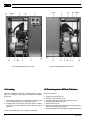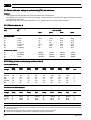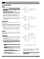
1
Instruction book for compressors
GA11 - GA15 - GA18 - GA22
F1042
Important
This book applies exclusively:
1. To GA11 - GA15 - GA18 - GA22 equipped with an electronic regulator as shown on the
left above. For these compressors, this book must be used together with the "User
manual for electronic regulator for GA5 up to GA45 compressors"
2. To GA11 - GA15 - GA18 - GA22 with an electro-pneumatic regulator as shown on the left
below.
From serial number AII-217 792 onwards
F051
This instruction book meets the requirements for instructions specified by the
machinery directive 89/392/EEC and is valid for CE as well as non-CE labelled machines
Registration code
Collection: APC G11-22
Tab:
38
Sequence: 0992
Replaces
No. 2920 1256 00
No. 2920 1256 01
Industrial Air Division - B-2610 Wilrijk - Belgium
1995-09
*2920125601*
Industrial Air Division
Instruction book
This instruction book describes how to handle the machines to ensure safe operation, optimum efficiency and long service life.
Read this book before putting the machine into operation to ensure correct handling, operation and proper maintenance from the beginning.
The maintenance schedule comprises measures for keeping the machine in good condition.
Keep the book available for the operator and make sure that the machine is operated and that maintenance is carried out according to the
instructions. Record all operating data, maintenance performed, etc. in an operator's logbook available from Atlas Copco. Follow all relevant
safety precautions, including those mentioned on the cover of this book.
Repairs must be carried out by trained personnel from Atlas Copco who can be contacted for any further information.
In all correspondence always mention the type and the serial number, shown on the data plate.
For all data not mentioned in the text, see sections "Preventive maintenance schedule" and "Principal data".
The company reserves the right to make changes without prior notice.
CONTENTS
Page
1 Leading particulars . . . . . . . . . . . . . . . . . . . . . . . . . . . . . . . . 3
1.1 General description . . . . . . . . . . . . . . . . . . . . . . . . . . . . 3
1.1.1 Air flow . . . . . . . . . . . . . . . . . . . . . . . . . . . . . . . . 3
1.1.2 Oil system . . . . . . . . . . . . . . . . . . . . . . . . . . . . . 3
1.1.3 Cooling and condensate drain systems . . . . . . . 5
1.2 Unloading/loading system . . . . . . . . . . . . . . . . . . . . . . . 5
1.2.1 Unloading . . . . . . . . . . . . . . . . . . . . . . . . . . . . . . 5
1.2.2 Loading . . . . . . . . . . . . . . . . . . . . . . . . . . . . . . . 6
1.3 Electrical system for GA Pack / Full-feature . . . . . . . . . 6
1.4 Electronic control module for GA Pack / Full-feature . . . 8
1.4.1 Electronic regulator . . . . . . . . . . . . . . . . . . . . . . 8
1.4.2 Control panel . . . . . . . . . . . . . . . . . . . . . . . . . . 11
1.5 Electrical system for GA Standard Pack . . . . . . . . . . . 14
1.5.1 Regulator . . . . . . . . . . . . . . . . . . . . . . . . . . . . . 15
1.5.2 Control panel . . . . . . . . . . . . . . . . . . . . . . . . . . 15
1.6 Air dryer on GA Full-feature . . . . . . . . . . . . . . . . . . . . . 15
1.6.1 Compressed air circuit . . . . . . . . . . . . . . . . . . . 15
1.6.2 Refrigerant circuit . . . . . . . . . . . . . . . . . . . . . . . 15
2 Installation . . . . . . . . . . . . . . . . . . . . . . . . . . . . . . . . . . . . . 16
2.1 Dimension drawings . . . . . . . . . . . . . . . . . . . . . . . . . . . 16
2.2 Electric cable size, settings of overload relay and main
fuses . . . . . . . . . . . . . . . . . . . . . . . . . . . . . . . . . . . . . . . 18
2.2.1 Electric cable size . . . . . . . . . . . . . . . . . . . . . . 18
2.2.2 Setting of motor overload relay and fuse value 18
2.3 Installation proposals . . . . . . . . . . . . . . . . . . . . . . . . . . 19
2.4 Electrical connections . . . . . . . . . . . . . . . . . . . . . . . . . 22
2.5 Pictographs . . . . . . . . . . . . . . . . . . . . . . . . . . . . . . . . . 23
3 Operating instructions . . . . . . . . . . . . . . . . . . . . . . . . . . . .
3.1 Before initial start-up . . . . . . . . . . . . . . . . . . . . . . . . . .
3.1.1 Safety precautions . . . . . . . . . . . . . . . . . . . . . .
3.1.2 User manual (GA Pack / Full-feature only) . . .
3.1.3 Outdoor/altitude operation . . . . . . . . . . . . . . . .
3.1.4 Handling . . . . . . . . . . . . . . . . . . . . . . . . . . . . . .
3.1.5 External compressor status indication
(GA Pack / Full-feature only) . . . . . . . . . . . . . .
3.1.6 Compressor control modes (GA Pack / Fullfeature only) . . . . . . . . . . . . . . . . . . . . . . . . . . .
3.2 Initial start-up . . . . . . . . . . . . . . . . . . . . . . . . . . . . . . . .
3.3 Starting . . . . . . . . . . . . . . . . . . . . . . . . . . . . . . . . . . . . .
3.4 During operation . . . . . . . . . . . . . . . . . . . . . . . . . . . . . .
3.4.1 Checking the display (GA Pack /
Full-feature only) . . . . . . . . . . . . . . . . . . . . . . .
3.5 Manual control for GA Pack / Full-feature . . . . . . . . . .
3.6 Stopping . . . . . . . . . . . . . . . . . . . . . . . . . . . . . . . . . . . .
3.7 Taking out of operation at end of compressor
service life . . . . . . . . . . . . . . . . . . . . . . . . . . . . . . . . . .
2
24
24
24
24
24
24
24
24
24
25
25
25
26
26
Page
4 Maintenance . . . . . . . . . . . . . . . . . . . . . . . . . . . . . . . . . . . . 26
4.1 Compressor motor . . . . . . . . . . . . . . . . . . . . . . . . . . . . 26
4.2 Preventive maintenance schedule for the compressor 27
4.3 Oil and oil filter change interval . . . . . . . . . . . . . . . . . . 28
4.4 Oil specifications . . . . . . . . . . . . . . . . . . . . . . . . . . . . . 28
4.4.1 Atlas Copco Roto-injectfluid . . . . . . . . . . . . . . . 28
4.4.2 Mineral oil . . . . . . . . . . . . . . . . . . . . . . . . . . . . . 28
4.5 Oil and oil filter change . . . . . . . . . . . . . . . . . . . . . . . . . 28
4.6 Storage after installation . . . . . . . . . . . . . . . . . . . . . . . 29
4.7 Service kits . . . . . . . . . . . . . . . . . . . . . . . . . . . . . . . . . . 29
5 Adjustments and servicing procedures . . . . . . . . . . . . . .
5.1 Air filter . . . . . . . . . . . . . . . . . . . . . . . . . . . . . . . . . . . . .
5.2 Coolers . . . . . . . . . . . . . . . . . . . . . . . . . . . . . . . . . . . . .
5.3 Safety valve . . . . . . . . . . . . . . . . . . . . . . . . . . . . . . . . .
5.4 Belt set exchange . . . . . . . . . . . . . . . . . . . . . . . . . . . . .
5.5 Fan control switch on GA Full-feature . . . . . . . . . . . . .
5.6 High pressure shut-down switch on GA Full-feature . .
5.7 Expansion valve on GA Full-feature . . . . . . . . . . . . . . .
5.8 Load/unload pressure switch on GA Standard Pack . .
5.9 Temperature shut-down switch on GA Standard Pack .
29
29
29
29
29
29
29
29
30
30
6 Problem solving . . . . . . . . . . . . . . . . . . . . . . . . . . . . . . . . . 31
7 Principal data . . . . . . . . . . . . . . . . . . . . . . . . . . . . . . . . . . . 33
7.1 Readings . . . . . . . . . . . . . . . . . . . . . . . . . . . . . . . . . . . 33
7.1.1 Readings on display on GA Pack / Full-feature 33
7.1.2 Readings on gauges on GA Standard Pack . . 33
7.2 Setting of safety valve . . . . . . . . . . . . . . . . . . . . . . . . . 33
7.3 Dryer control switches and refrigerant specifications on
GA Full-feature . . . . . . . . . . . . . . . . . . . . . . . . . . . . . . . 33
7.4 Compressor specifications . . . . . . . . . . . . . . . . . . . . . . 33
7.4.1 Reference conditions . . . . . . . . . . . . . . . . . . . . 33
7.4.2 Limitations . . . . . . . . . . . . . . . . . . . . . . . . . . . . 33
7.4.3 Specifications of GA 7.5 bar . . . . . . . . . . . . . . 34
7.4.4 Specifications of GA 10 bar . . . . . . . . . . . . . . . 34
7.4.5 Specifications of GA 13 bar . . . . . . . . . . . . . . . 34
7.4.6 Specifications of GA 100 psi . . . . . . . . . . . . . . 35
7.4.7 Specifications of GA 125 psi . . . . . . . . . . . . . . 35
7.4.8 Specifications of GA 150 psi . . . . . . . . . . . . . . 36
7.4.9 Specifications of GA 175 psi . . . . . . . . . . . . . . 36
7.5 Conversion list of SI units into US/British units . . . . . . 36
26
2920 1256 01
Instruction book
Industrial Air Division
Options and special versions
1 LEADING P
AR
TICULARS
PAR
ARTICULARS
1.1 General description
FullPack
feature
GA are stationary, single-stage, oil-injected screw compressors driven
by an electric motor. GA11 up to GA22 are air-cooled.
GA Standard Pack (Figs. 3)
The compressors are enclosed in a sound-insulated bodywork. A
control panel including the start/stop switch is provided. An electric
cabinet comprising the relay-controlled regulator and motor starter is
located behind this panel.
GA Pack (Figs. 2)
The compressors are enclosed in a sound-insulated bodywork. The
front panel comprises an electronic control module including the start
and stop buttons. An emergency stop button is also provided. An
electric cabinet comprising the motor starter is located behind this
panel. An automatic condensate drain system is provided.
GA Full-feature (Fig. 1)
GA Full-feature are GA Pack compressors additionally provided with
an air dryer integrated in the bodywork. The dryer removes moisture
from the compressed air by cooling the air to near freezing point and
automatically draining the condensate. See section 1.6.
Energy recovery kit ............................. 0
Integrated oil separator (OSD) 1) ....... 0
High ambient version (up to 50 C) ...... NA
Public works version ........................... 0
Oil protecting frame plate .................... 0
Modulating control regulator ............... 0
Integrated condensate
separator (WSD) ................................. S
Integrated dryer ................................... S
8 bar version ....................................... 0
Electronic drain ................................... 0
Dryer by-pass ...................................... 0
Silencing kit ......................................... 0
Relay expansion box ........................... 0
0 = optional
S = standard
Standard
Pack
0
0
0
0
0
0
NA
0
0
0
0
0
S
0
0
0
0
0
0
0
NA
0
0
NA
0
NA
NA = not available
1.1.1 Air flow (Fig. 4)
1
E
OF
2 Ca/Co 8 VP 7
Air drawn through filter (AF) and open inlet valve (IV) into compressor
element (E) is compressed. The compressed air flows through oil
separator (OS), minimum pressure valve (Vp) and air cooler (Ca) to
outlet valve (AV).
1.1.2 Oil system (Fig. 4)
Air pressure forces the oil from air receiver (AR) through oil cooler
(Co) and filter (OF) to compressor element (E) and the lubrication
points.
The system comprises a by-pass valve (BV). When the oil temperature
is below 40 C (104 F) 2)
2), there is no oil flow to the oil cooler. At
approx. 55 C (131 F) 2)
2), the valve is closed so that all the oil passes
through the cooler.
F058
DP2
M1
4
3 FN
1) If an oil separator is desired for Pack and Full-feature compressors
equipped with an energy recovery kit, a freestanding OSD must be
applied.
2) For 13 bar/175 psi compressors, these temperatures are 60 C (140 F)
and 75 C (167 F) respectively
Fig. 1. GA22 Full-feature
2920 1256 01
3
Industrial Air Division
Instruction book
MT
SV
AF
VI
E
OF
BV
AV
4
3
F057
Dm1
Da
DP2
M1
Fig. 2a. GA Pack, motor side
AF.
AR.
AV.
BV.
Ca.
Co.
Da.
Air filter
Air receiver
Air outlet valve
By-pass valve, oil circuit
Air cooler
Oil cooler
Automatic condensate drain
outlet
Dm1.
Manual condensate drain valve
DP1/DP2. Oil drain plugs
E.
Compressor element
FC.
FN.
Gl.
M1.
MT.
OF.
PSR19.
SV.
VI.
VP.
Vp.
Oil filler plug
Compressor cooling fan
Oil level indicator
Motor
Moisture trap
Oil filter
Load/unload pressure switch
Safety valve
Air filter service indicator
Vent plug, oil circuit
Minimum pressure valve
1.
2.
3.
Dryer
Control panel
Arrow, direction of rotation of drive
motor
4. Motor voltage supply
5. Belt tensioning bolt
6. Transport spacer/bolt
7. Side panel
8. Bolt
9. Bolt
10. Arrow, direction of rotation of drive
motor
Figs. 1 up to 3. General views
4
2920 1256 01
Instruction book
Industrial Air Division
F059
F059
10
FN
Fig. 2b. GA Pack/Full-feature, receiver side
1.1.3 Cooling and condensate drain systems
The cooling system comprises air cooler (Ca-Fig. 1) and oil cooler
(Co). The cooling air is generated by fan (FN).
A moisture trap (MT-Fig. 2a) is provided in the air outlet system of GA
Pack and Full-feature compressors. 1)
1). The trap is equipped with a
valve for automatic condensate draining during operation (Da) and a
manually operated valve for draining after stopping the compressor
(Dm1).
1.2 Unloading/loading system (Fig. 4)
the net pressure increases. When the net pressure reaches the
unloading pressure, solenoid valve (Y1) is de-energized. The plunger
of the valve returns by spring force:
1. The control pressure present in the chambers of loading plunger
(LP) and unloading valve (UV) is vented to atmosphere via
solenoid valve (Y1).
2. Loading plunger (LP) moves upwards and causes inlet valve (IV)
to close the air inlet opening.
3. Unloading valve (UV) is opened by receiver pressure. The
pressure from air receiver (AR) is released towards unloader (UA).
Air output is stopped (0 %), the compressor runs unloaded.
1.2.1 Unloading
If the air consumption is less than the air output of the compressor,
2920 1256 01
1) Available as option on GA Standard Pack.
5
Industrial Air Division
Instruction book
Fig. 3b. GA18 Standard Pack, receiver side
Fig. 3a. GA18 Standard Pack, motor side
1.2.2 Loading
1.3 Electrical system for GA Pack / Full-feature
When the net pressure decreases to the loading pressure, solenoid
valve (Y1) is energized. The plunger of the valve moves against
spring force:
The system comprises:
1. Control pressure is fed from air receiver (AR) via solenoid valve
(Y1) to loading plunger (LP) and unloading valve (UV).
2. Unloading valve (UV) closes the air blow-off opening. Loading
plunger (LP) moves downwards and causes inlet valve (IV) to
open fully.
1.
2.
3.
4.
5.
6.
Compressor motor (M1-Fig. 2a)
Electronic control module (Fig. 7a)
Compressor start button (I) and stop button (O) (Fig. 7a)
Emergency stop button (S3-Fig. 7a)
Electric cabinet (Fig. 5a)
Sensors for the compressor element outlet temperature (TT11)
and for the air outlet pressure (PT20)
7. Dewpoint temperature sensor (TT90) for Full-feature compressors
Air output is resumed (100 %), the compressor runs loaded.
6
2920 1256 01
Instruction book
AF.
AR.
AV.
BV.
Ca.
Co.
Da.
Air filter
Air receiver
Air outlet valve
Oil cooler by-pass valve
Air cooler
Oil cooler
Automatic condensate drain
outlet
Dm1.
Manual condensate drain valve
DP1/DP2. Oil drain plugs
E.
Compressor element
E1.
Control module
FC.
Oil filler plug
FN.
Fan
Gl.
Oil level indicator
Industrial Air Division
IV.
LP.
M1.
MT.
OF.
OS.
PT20.
SV.
TT90.
UA.
UV.
VI.
Vp.
VP.
Y1.
Inlet valve
Loading plunger
Compressor motor
Moisture trap
Oil filter
Oil separator element
Pressure sensor, air outlet
Safety valve
Temperature sensor, dewpoint
Unloader
Unloading valve
Air filter service indicator
Minimum pressure valve
Vent plug, oil circuit
Loading solenoid valve
1.
2.
3.
Oil scavenging line
Flexible, control air
Belts
On Full-feature also:
FN1. Fan, dryer condenser
M1. Refrigerant compressor
M2. Motor, condenser fan
4.
Expansion valve
5.
Air/air heat exchanger
6.
Air/refrigerant heat exchanger
(evaporator)
7.
Liquid separator
8.
Condenser
9.
Liquid receiver
Fig. 4. GA Pack/Full-feature during loading
2920 1256 01
7
Industrial Air Division
1.4 Electronic control module for GA Pack / Fullfeature
The control module consists of an electronic regulator and a control
panel.
1.4.1 Electronic regulator (E1-Fig. 6a)
The regulator has following functions:
Controlling the compressor
The regulator maintains the net pressure between programmable limits
by automatically loading and unloading the compressor. A number of
programmable settings, e.g. the unloading and loading pressures,
the minimum stop time and the maximum number of motor starts are
taken into account.
Instruction book
The regulator stops the compressor whenever possible to reduce the
power consumption and restarts it automatically when the net pressure
decreases. In case the expected unloading period is too short, the
compressor is kept running to prevent too-short standstill periods.
Protecting the compressor
If the compressor element outlet temperature exceeds the
programmed shut-down level, the compressor will be stopped. This
will be indicated on the control panel (Fig. 7a). The compressor will
also be stopped in case of overload of compressor motor (M1).
If the compressor element outlet temperature exceeds a programmed
value below the shut-down level, this will also be indicated to warn
the operator before the shut-down level is reached.
See legend of Figs. 6 for denomination of components
See legend of Figs. 8 for denomination of components
Fig. 5a. Electric cabinet of GA Pack / Full-feature (typical example)
Fig. 5b. Electric cabinet of GA Standard Pack (typical example)
8
2920 1256 01
Instruction book
Industrial Air Division
Fig. 6a. Electrical diagram, GA Pack / Full-feature (50 Hz / star-delta)
2920 1256 01
9
Industrial Air Division
Instruction book
Fig. 6b. Electrical diagram, dryer on GA Full-feature
SENSORS/LOADING SOLENOID VALVE
PT20. Pressure sensor, air outlet
TT11. Temperature sensor, compressor
element outlet
TT90. Temperature sensor, dewpoint 1)
Y1.
Loading solenoid valve
Y2.
Solenoid valve, modulating control
(optional)
F21.
K11.
K21.
K22.
K23.
T1/T2.
1X1.
1X2.
MOTORS
M1. Compressor motor
CONTROL MODULE (E1)
I.
Start button
K01. Blocking relay
K02. Auxiliary relay, star contactor
K03. Auxiliary relay, delta contactor
K04. Auxiliary relay, loading/unloading
ELECTRIC CABINET
E2.
Relay expansion box (optional)
F1/F5. Fuses
Overload relay, compressor motor
Auxiliary contactor for dryer 1)
Line contactor
Star contactor
Delta contactor
Transformers
Terminal strip
Terminal strip
K05.
K10.
O.
S3.
2X1/6.
Auxiliary relay, high/low air pressure
Auxiliary relay, dryer
Stop button
Emergency stop button
Connectors
On GA Full-feature also:
F0.
Fuses (customer's installation)
C1.
Capacitor
M1. Refrigerant compressor/motor
M2. Motor, condenser cooling fan
S3.
Control switch, condenser cooling
fan
1)
Only for Full-feature compressors.
Figs. 6. Electrical diagrams for GA Pack / Full-feature
Monitoring components subject to service
The regulator continuously monitors the oil, oil filter, oil separator and
air filter. Each input is compared to programmed time intervals. If
these limits are exceeded, a message will appear on the display (Fig.
7a) to warn the operator to replace the indicated component. The
number of the service kit will appear on the display.
10
Automatic restart after voltage failure
For compressors leaving the factory, this function is made inactive. If
desired, the function can be activated. Consult Atlas Copco.
If activated and provided the module was in the automatic operation
mode, the compressor will automatically restart if the supply voltage
to the module is restored within a programmed time period.
2920 1256 01
Instruction book
Industrial Air Division
1.4.2 Control panel (Fig. 7a)
Indicators, keys and buttons
To control the compressor and to read and modify programmable
parameters, the regulator is provided with a panel including:
1 Automatic operation LED
Indicates that the regulator is automatically controlling the
compressor: the compressor is loaded, unloaded, stopped
and restarted depending on the air consumption and the
limitations programmed in the regulator.
2 Voltage on LED
Indicates that the voltage is switched on.
3 General alarm LED
Is normally out. Is alight or blinks in case of an abnormal
condition. See below.
4 Display
Indicates:
the name of the sensor of which the actual reading is
displayed
the unit and actual reading
messages regarding the operating status, a sensor
error, a service need or a fault
5 Function keys
Keys to control and program the compressor. The actual
function of each key is abbreviated and indicated on the bottom
line. The most common ones are listed below.
S3.
1.
2.
3.
4.
5.
6.
7.
8 Start button
Push button to start the compressor. LED (1) lights up
indicating that the regulator is operative (in automatic
operation). The LED goes out after unloading the compressor
manually.
8. Start button
9. Stop button
10. Pictograph, emergency
stop
11. Pictograph, automatic
operation
12. Pictograph, voltage on
13. Pictograph, alarm
Fig. 7a. Control panel of GA Pack / Full-feature
6 Scroll keys
As long as an arrow is shown on the right side of the display,
the key with the same symbol can be used to scroll through
the display.
7 Tabulator key
Key to go to the next field of the display.
Emergency stop button
LED, automatic operation
LED, voltage on
LED, general alarm
Display
Function keys
Scroll keys
Tabulator key
Delivery air
bar
Auto loaded
Menu
F1
7.0
More
Unld
F2
F3
Fig. 7b. Example of the main display
9 Stop button
Push button to stop the compressor. LED (1) goes out. The
compressor will stop after running in unloaded condition for
30 seconds.
S3 Emergency stop button
Push button to stop the compressor immediately in case of
emergency. Must be unlocked before restarting.
Status data
↓
Main
Slct
F1
F2
F3
Fig. 7c. Example of a main menu
2920 1256 01
11
Industrial Air Division
Instruction book
Fig. 8a. Electrical diagram, GA Standard Pack, star-delta, without transformer
12
2920 1256 01
Fig. 8b. Electrical diagram, GA Standard Pack, star-delta, with transformer
2920 1256 01
F1/3. Fuses
F21. Overload relay, compressor
motor
K21. Line contactor
K22. Star contactor
K23. Delta contactor
K24. Time relay, star/delta switch-over (10 sec)
K26. Time relay, delayed motor stopping (5 min)
M1. Compressor motor
P1.
PSR19.
S1.
T1.
TSHH11.
Y1.
Y2.
1X1.
1X2.
Hourmeter, total running time
Load/unload pressure switch
Start/stop switch
Transformer
Temperature shut-down switch
Loading solenoid valve
Solenoid valve, modulating control (optional)
Terminal strip
Terminal strip
Figs. 8. Electrical diagrams, GA Standard Pack
Instruction book
Industrial Air Division
13
Industrial Air Division
General alarm LED (3-Fig. 7a) 1)
- The LED blinks in case of a shut-down (due to either too high
a compressor element outlet temperature or overload of the
compressor motor); at the same time the shut-down screen
appears. Remedy; see section 6. After eliminating the cause
of the trouble and when the abnormal condition has
disappeared, press key <<Rset>> (5).
- The LED blinks and the compressor is shut down if the sensor
of the compressor element (TT11) is out of order; at the same
time the display will show a fault message. Switch off the
voltage, depressurize and check the sensor and its wiring.
- The LED is alight in case of a shut-down warning; at the same
time a warning message appears. Remedy; see section 6.
- The LED is alight if the dewpoint sensor (TT90) is out of order
(on Full-feature compressors); at the same time a fault
message is shown. Stop the compressor, switch off the
voltage, depressurize and check the sensor and its wiring.
Instruction book
Selecting a menu
To facilitate controlling the compressor, menu-driven programs are
implemented in the electronic module. Use the function keys (5) to
select the menus in order to program and monitor the compressor.
The "User manual for electronic regulator for GA5 up to GA45
compressors" deals elaborately with all regulator functions.
Function keys
Abbre- Desigviation nation
Add
Canc
Del
Lim
List
Load
Main
Menu
Mod
More
Prog
Rset
Rtrn
Slct
Unld
Function
Add
To add compressor start/stop commands (day/
hour)
Cancel To cancel a programmed setting when
programming parameters
Delete To delete compressor start/stop commands
Limits
To show limits for a programmable setting
List
To list programmed start/stop commands (day/
hour)
Load
To load the compressor manually
Main
To return from a menu to the main display (Fig.
7b)
Menu
Starting from the main display (Fig. 7b), to
initiate the main menu (Fig. 7c) which gives
access to submenus
Starting from a submenu, to return to the main
menu (Fig. 7c)
Modify To modify programmable settings
More
To have a quick look at the compressor status
Program To program modified settings
Reset
To reset a timer or message
Return To return to a previously shown option or menu
Select To select a submenu or to read more details of
a selection shown on display
Unload To unload the compressor manually
1.5 Electrical system for GA Standard Pack
Gp.
P1.
S1.
TSHH11.
1.
2.
3.
4.
5.
Gauge indicating the working pressure
Hourmeter indicating the total motor running time
Switch to start or stop the compressor
Gauge/switch, indicating the temperature at the outlet
of the compressor element as well as the shut-down
temperature; the regulator then stops the compressor
Pictograph, working pressure
Pictograph, outlet temperature of compressor element
Pictograph, running hours
Pictograph, compressor stop
Pictograph, compressor start
Fig. 9. Control panel of GA Standard Pack
14
The system comprises:
1. Compressor motor (M1-Fig. 3a)
2. Regulator (Fig. 5b)
3. Control panel with start/stop switch (S1-Fig. 9)
4. Temperature shut-down switch (TSHH11-Fig. 9)
5. Load/unload pressure switch (PSR19-Fig. 14)
1) Consult the User manual for the electronic regulator, section "Status
data submenu".
2920 1256 01
Instruction book
Industrial Air Division
1.5.1 Regulator (Fig. 5b)
1.6 Air dryer on GA Full-feature (Fig. 4)
The regulator loads, unloads, stops and restarts the compressor
according to the air consumption, and protects the compressor and
motor from overloads. The unloading and loading pressures are the
opening and closing pressures respectively of switch (PSR19). See
section 5.8.
GA Full-feature are provided with a dryer which removes moisture
from the compressed air. See Fig. 6b for the electrical diagram.
Delayed motor stopping
The time relay for delayed motor stopping (K26) limits the frequency
of automatic motor starts by stopping the motor only after a set time
of 5 minutes of uninterrupted unloaded operation. If the net pressure
drops to the loading pressure within the set unloading time, the
compressor will be loaded without stopping.
1.6.1 Compressed air circuit
Compressor temper
ature shut-do
wn sswitch
witch (TSHH11)
temperature
shut-down
The switch prevents damage resulting from too high a temperature
at the outlet of the compressor element.
Compressed air enters heat exchanger (5) and is cooled by the
outgoing, cold, dried air. Water in the incoming air starts to condense.
The air then flows through heat exchanger (6) where the refrigerant
evaporates and withdraws heat from the air. This cools the air to
close to the evaporating temperature of the refrigerant. More water
in the air condenses. The cold air then flows through moisture trap
(MT) where all the condensate is separated from the air. The
condensate is automatically drained through outlet (Da). The cold
dried air then flows through heat exchanger (5), where it is warmed
up by the incoming air.
Motor overload relay (F21)
The relay prevents damage resulting from too high a motor current.
1.6.2 Refrigerant circuit
1.5.2 Control panel (Fig. 9)
Gp.
P1.
S1.
TSHH11.
1.
2.
3.
4.
5.
Gauge indicating the working pressure
Hourmeter indicating the total motor running time
Switch to start or stop the compressor
Gauge/switch, indicating the temperature at the outlet of
the compressor element as well as the shut-down
temperature; the regulator then stops the compressor
Pictograph, working pressure
Pictograph, outlet temperature of compressor element
Pictograph, running hours
Pictograph, compressor stop
Pictograph, compressor start
2920 1256 01
Compressor (M1) delivers high-pressure refrigerant gas which flows
via liquid separator (7) through condenser (8) where most of the
refrigerant condenses. The cooled refrigerant then collects in receiver
(9).
The liquid flows to expansion valve (4) where it expands to evaporating
pressure. The refrigerant enters evaporator (6) where it withdraws
heat from the compressed air by further evaporation. The vapour
refrigerant leaving evaporator (6) flows into liquid separator (7) and
is sucked in by compressor (M1).
15
Industrial Air Division
Instruction book
2 INST
ALLA
TION
INSTALLA
ALLATION
2.1 Dimension drawings (Figs. 10)
Fig. 10a. Dimension drawing for GA Pack and Full-feature
16
2920 1256 01
Instruction book
Industrial Air Division
Fig. 10b. Dimension drawing for GA Standard Pack
2920 1256 01
17
Industrial Air Division
Instruction book
2.2 Electric cable size, settings of overload relay (F21) and main fuses
Attention
- Local regulations remain applicable if they are stricter than the values proposed below.
- The voltage drop must not exceed 5 % of the nominal voltage. It may be necessary to use cables with a larger section than those stated
to comply with this requirement.
- Max. cable length = 25 m, max. ambient temperature = 40 C, cables in free air or in raceway, copper conductors.
2.2.1 Electric cable size 1)
Frequency
(Hz)
Supply voltage
(V)
GA11
Cable size
WG)
AWG)
(mm2 or A
GA15
GA18
GA22
3 x 230
3 x 400
3 x 500
3 x 220/230
3 x 380
3 x 440/460
10/16
4/6
4/4
10/16
4/6
4/6
16/16
6/10
6/6
16/25
10/10
6/10
25/25
10/16
6/10
25/35
10/16
10/10
35/35
10/16
10/10
35/35
16/16
10/16
3 x 220/230
3 x 440/460
3 x 575
AWG6/4
AWG10/8
AWG10/10
AWG4/4
AWG8/6
AWG10/8
AWG4/3
AWG8/6
AWG8/6
AWG3/2
AWG6/6
AWG8/6
Star-delta starter
50
50
50
60
60
60
Direct-on-line starter
60
60
60
2.2.2 Setting of motor overload relay and fuse value 2)
For star-delta starter 3)
Voltage
GA11
Relay
GA11
Fuse
GA15
Relay
GA15
Fuse
GA18
Relay
GA18
Fuse
GA22
Relay
GA22
Fuse
Unit
230
220-230
380
400
440-460
500
26/-/26
-/15
15/-/13
12/-
63/-/63
-/35
35/-/35
25/-
35/-/37
-/21
20/-/19
16/-
80/-/80
-/50
50/-/50
35/-
43/-/43
-/25
25/-/22
20/-
100/-/100
-/63
63/-/50
35/-
48/-/50
-/29
28/-/25
22/-
100/-/100
-/63
63/-/63
50/-
A
A
A
A
A
A
For direct-on-line starter (60 Hz) 4)
Voltage
GA11
Relay
GA11
Fuse
GA15
Relay
GA15
Fuse
GA18
Relay
GA18
Fuse
GA22
Relay
GA22
Fuse
Unit
220-230
440-460
575
45
23
17
80/70
60/60
60/60
64
32
25
125/125
80/70
60/60
75
37
29
150/150
80/70
80/70
87
43
33
200/175
80/70
80/70
A
A
A
1) Figures before the slant apply to Standard Pack, figures behind it apply to Pack and Full-feature.
2) The indicated value is the maximum fuse value with regard to short circuit protection of the starter. The cable size of the used supply cables may impose
fuses of a lower value.
3) Figures before the slant apply to 50 Hz compressors, figures behind it apply to 60 Hz compressors.
4) Figures before the slant apply to CSA HRC fuses, figures behind it apply to UL class K5 fuses.
18
2920 1256 01
Instruction book
Industrial Air Division
2.3 Installation proposals (Figs
(Figs.. 11)
Fig. 11a. Installation proposal for GA Pack and Full-feature
2920 1256 01
19
Industrial Air Division
Instruction book
Fig. 11b. Installation proposal for GA Standard Pack
20
2920 1256 01
Instruction book
Industrial Air Division
Ref.
Description/recommendation
F or Standard P
ac
Pac
ackk also (Fig. 11b):
1
Install the compressor on a level floor suitable for taking the
weight of the compressor, and with a minimum clearance of
1.2 m above the unit except for ventilation proposals 2 and
4.
8
2
Position of compressed air outlet valve.
3
The maximum total pipe length (including interconnecting
piping between compressor and receiver) can be calculated
as follows:
Optional filters can be installed in the pressure line
downstream of the outlet valve:
A DD filter for general-purpose filtration (filter traps
solid particles down to 1 micron with max. oil carryover of 0.5 mg/m ).
A high-efficiency PD filter (traps solid particles down
to 0.01 micron with max. oil carry-over of 0.01 mg/m ).
A PD filter must be installed downstream of a DD
filter.
If oil vapour and odours are undesirable, a filter of the
QD type should be installed downstream of the PD
filter.
450 x Qc1.85
9
Position of receiver safety valve
pipe length in m
maximum allowable pressure drop
(recommended 0.1 bar)
inner diameter of pipe in mm
compressor outlet pressure in bar absolute
free air delivery of compressor in l/s
-
A condensate trap is available as option
-
The air receiver (optional) should be installed in a frost-free
room and on a level concrete foundation.
∆P x d5 x P
L
=
L
=
∆P =
d
=
P =
Qc =
4
_________________
Ventilation: the inlet grids and ventilation fan should be
installed in such a way that any recirculation of cooling air
to the compressor or dryer is avoided. The air velocity to
the grids must be limited to 5 m/s. The maximum allowable
pressure drop over the cooling air ducts is 30 Pa. If this
pressure drop is exceeded, a fan is needed at the outlet of
the cooling air ducts. The maximum air temperature at the
compressor intake opening is 40 C (minimum 0 C).
7.5 x Q x P
V
=
_______________
V
Q
P
∆P
=
=
=
=
volume of air net in l
free air delivery of compressor in l/s
compressor air inlet pressure in bar absolute
Punload - Pload in bar
∆P
The required ventilation to limit the compressor room
temperature can be calculated as follows:
F or P
ac
eature also (Fig. 11a):
Pac
ackk and Full-f
Full-feature
For alternatives 1 and 3: Qv = 0.92 N/∆T
8
Provision for energy recovery system
9
Optional filters can be installed in the pressure line
downstream of the outlet valve, see reference 8 above.
10
Position of receiver safety valve
11
Dryer by-pass pipe, to be used to by-pass the dryer in case
of servicing the dryer. Consult Atlas Copco.
12
Optional condensate trap and valve, can be used during
servicing of the dryer. Consult Atlas Copco.
13
Provision for oil separation system (Atlas Copco OSD-type
oil separator). Consult Atlas Copco.
-
The air receiver (optional) should be installed in a frost-free
room and on a level concrete foundation.
Qv =
N =
∆T =
required ventilation capacity in m3/s
shaft input of compressor in kW
temperature increase in compressor room
For alternatives 2 and 4, the fan capacity should match the
compressor fan capacity at a pressure head equal to the
pressure drop caused by the cooling air outlet ducts.
5
For normal air consumption, the volume of the air net
(receiver and piping) can be calculated as follows:
Position of condensate drain flexibles. The flexibles
towards the drain collector must not dip into the water of
the drain collector. Atlas Copco has oil separators (type
OSD) to separate the major part of oil from condensate to
ensure that the condensate meets the requirements of the
environmental codes (see also reference 13 below)
6
Position of control panel.
7
Position of mains cables entry. See section 2.2 for the
recommended electric cables. See section 2.4 for
connecting the power supply.
2920 1256 01
For normal air consumption, the volume of the air net
(receiver and piping) can be calculated as described above.
21
Industrial Air Division
Instruction book
2.4 Electrical connections
General
- The installation must include an isolating switch near to and visible
witch is open to
from the compressor. Mak
Makee sure that this sswitch
isolate the compressor from the mains before carrying out
any connection
connection.
- See section 2.2 for the size of the electric cables.
- The installation must be earthed and protected against short
circuits by fuses of the inert type in each phase. See section 2.2.
- The electrical connections must correspond to the local codes.
- The indications on the data plate of the drive motor must
correspond to the mains supply voltage and frequency.
- Check the fuses and the setting of the overload relay. See section
2.2.
- Lay-out the power supply cables under the compressor frame
and then through the bottom of the electric cabinet via a 90 elbow
(is delivered loose).
On GA Standard Pack
Connect the power supply to terminals (L1, L2 and L3) of terminal
strip (1X2-Fig. 5b).
For compressors with voltage transformer, check that the connections
at the primary side of the transformer correspond to the mains voltage.
For compressors without voltage transformer, check the connection
of wire (2):
- either towards the neutral terminal (N) in case of a 3 x 400 V plus
neutral mains; connect the neutral conductor to terminal (N).
- or towards terminal (2) of fuse F2 in case of a 3 x 230 V mains
On GA Pack
Connect the power supply to terminals (L1, L2 and L3) of terminal
strip (1X2-Fig. 5a). Connect the neutral conductor to terminal (N).
Consult section 2.2.
On GA Full-feature
- Connect the power supply to terminals (L1, L2 and L3) of terminal
strip (1X2-Fig. 5a). Connect the neutral conductor to terminal
(N). Consult section 2.2.
- The voltage to the dryer is supplied over the contacts of relay
(K11-Fig. 5a), which close when the compressor is started.
oltage supply to the dr
ust be single-phase 230 V.
- The vvoltage
dryy er m
must
The voltage may be branched off directly from the mains supply
or via an optional voltage transformer.
1. The dryer voltage supply is branched off from the mains
supply
-
-
-
22
For a compressor supply voltage of 3 x 400 V plus neutral
conductor (A-Fig. 12):
The dryer supply voltage is branched off between a phase
conductor and the neutral conductor.
For a compressor supply voltage of 3 x 230 V (B-Fig. 12):
The dryer supply voltage is branched off between two phase
conductors.
For all other supply voltages (C-Fig. 12):
A separate single-phase 230 V voltage supply must be
Fig. 12. Dryer connections on GA Full-feature
provided. Use wiring of minimum 1.5 mm . The dryer must
be protected by fuses of 10 A (except for 60 Hz CSA/UL: 8 A
for GA11/15 and 12 A for GA18/22).
2. The dryer voltage is branched off from the optional
voltage transformer
The correct connections are shown on diagram D-Fig. 12.
2920 1256 01
Instruction book
Industrial Air Division
2.5 Pictographs
Fig. 13 shows typical examples of pictographs used for GA compressors. See also Fig. 9.
1.
2.
3.
4.
5.
6.
7.
8.
9.
Water outlet
Water inlet
Manual condensate drain
Automatic condensate drain
Before connecting compressor electrically, consult instruction
book for motor rotation direction
Torques for steel (Fe) or brass (CuZn) bolts
Consult Instruction book before greasing
Switch off voltage before removing protecting cover inside
electric cubicle
Switch off voltage and depressurize compressor before
repairing
Fig. 13. Pictographs
2920 1256 01
23
Industrial Air Division
3 OPERA
TING INSTR
UCTIONS
OPERATING
INSTRUCTIONS
3.1 Before initial start-up
3.1.1 Safety precautions
The operator must apply all relevant safety precautions, including
those mentioned in this book.
3.1.2 User manual (GA Pack / Full-feature only)
Read the "User manual for electronic regulator for GA5 up to GA45
compressors" to familiarize yourself with all regulator functions.
3.1.3 Outdoor/altitude operation
If the compressor is installed outdoors or if the air inlet temperature
can be below 0 C (32 F), precautions must be taken. In this case,
and also if operating at high altitude, consult Atlas Copco.
3.1.4 Handling
The bottom frame of the compressor is designed for easy handling
with a pallet truck. The compressor can pass through a standard
door (width 800 mm)
3.1.5 External compressor status indication (GA
Pack / Full-feature only)
A relay box for external compressor status indication (E2-Fig. 5a) is
available as option. It can be connected to the electronic control
module (E1). The relay box has relays for indication of:
-
manual load/unload or automatic operation (K06)
warning condition (K07)
shut-down condition (K08)
Maximum load for these contacts: 1 A / 240 V AC. Stop the compressor
and switch off the voltage before connecting external equipment.
3.1.6 Compressor control modes (GA Pack / Fullfeature only)
The electronic regulator has two switches (CMS1/2-Fig. 5a) on strip
(1X1) to select following compressor control modes (0 = open /
1 = closed):
Instruction book
CMS1
CMS2
Compressor mode
0
0
Compressor off
1
0
Compressor in local control mode (remote
control is made inactive).
0
1
1 or
1
Compressor in remote control mode (local
control is made inactive).
For remote starting and stopping: Connect
one side of a remote start button (normally open
contact) to terminal 3 of connector (2X4) 1)
1).
Connect one side of a remote stop button
(normally closed contact) to terminal 4 of
connector (2X4) 1)
1). Bridge the other sides of
these buttons. Connect this common joint to
terminal 2 of connector (2X4).
Bridge terminal 28 of strip (1X1-Fig. 5a) and
terminal 6 of connector (2X4) 1)
1). In this mode,
the outlet pressure is still sensed by pressure
transducer (PT20), resulting in loading and
unloading of the compressor at the pressures
programmed in the electronic regulator. If
terminals 28 and 6 are not bridged, the
compressor is switched out of automatic load/
unload operation and remains running
unloaded.
For remote loading/unloading (via external
pressure switch): Bridge terminal 28 of strip
(1X1-Fig. 5a) and terminal 7 of connector (2X4)
1) and connect a load/unload switch between
terminal 28 of strip (1X1-Fig. 5a) and terminal 6
of connector (2X4) 1)
1). This results in loading
and unloading of the compressor at the closing
and opening pressures of the external pressure
switch respectively.
Have the modifications checked by Atlas Copco. Stop the compressor
and switch off the voltage before connecting external equipment. Only
voltage-free contacts are allowed.
3.2 Initial start-up
1. Remove the transport bolts and spacers (6-Figs. 2 and 3).
2. Check that the electrical connections correspond to the local codes
and that all wires are clamped tight to their terminals. See section
2.4.
1) At the back of the electronic module.
24
2920 1256 01
Instruction book
3. Check the voltage selecting wires at the primary side of
transformer (T1-Fig. 5a) 1)
1), the setting of compressor motor
overload relay (F21), and that overload relay (F21) is set for
automatic resetting.
4. Fit air outlet valve (AV-Figs. 2 and 3). Close the valve. Connect
the air net to the valve.
5. Fit valve (Dm1-Fig. 2a). Close the valve. Connect the valve to a
drain collector. 2)
6. Connect the automatic drain outlet (Da-Fig. 2a) to a drain collector.
2)
7. The drain pipes to the drain collector must not dip into the water.
For draining of pure condensate water, install an oil/water
separator which is available from Atlas Copco as option. If the
pipes have been led down outside the room where freezing is
possible, they must be insulated.
8. Check the oil level. The pointer of level indicator (Gl-Figs. 2 and
3) should register in the green range or above it.
9. Stickers dealing in short with the operating instructions and
explaining the pictographs are delivered with the literature set.
Affix the stickers next to the control panel. Make yourself familiar
with the instructions and pictographs explained, as well as with
those mentioned in section 2.5.
10. Check the motor (M1-Figs. 2 and 3) for correct direction of rotation.
The rotation direction can be checked through the grating of the
compressor cooling fan. See Fig. 2b. The direction is indicated
by an arrow (10) stuck on the fan (FN).
The correct direction of rotation of the motor is counter-clockwise
when facing the cooling fan.
Switch off the voltage and reverse two of the voltage supply lines
if the direction of rotation is wrong.
11. On GA Pack / Full-feature, check the programmed settings. 3)
12. Start and run the compressor for a few minutes. Check that the
compressor operates normally.
3.3 Starting
For GA Pack / Full-feature (Fig. 7a)
1. Check the oil level: the pointer of level indicator (Gl-Fig. 2b) should
register in the green range or above it.
2. Switch on the voltage. Check that voltage on LED (2) lights up.
The message <<compressor off>> appears.
3. If the red part of service indicator (VI-Fig. 2a) shows completely
red, replace the air filter (AF-Fig. 2a).
4. Close condensate drain valve (Dm1-Fig. 2a).
5. Open air outlet valve (AV-Fig. 2a).
6. Press start button I (8). The compressor starts running and
automatic operation LED (1) lights up. Ten seconds 4) after
starting, the compressor motor switches over from star to delta.
At the same time 4) the compressor starts running loaded. The
message on display (4) changes from <<Auto unloaded>> to
<<Auto loaded>>.
For GA Standard Pack
1. Check the oil level: the pointer of level indicator (Gl-Fig. 3b) should
register in the green range or above it.
2. Switch on the voltage.
3. If the red part of service indicator (VI-Fig. 3a) shows completely
red, replace the air filter (AF-Fig. 3b).
2920 1256 01
Industrial Air Division
4. If installed, close the condensate drain valve. 2)
5. Open air outlet valve (AV-Fig. 3a).
6. Move switch (S1-Fig. 9) to "I".
3.4 During operation
1. Check the oil level during loaded operation
operation: the pointer of level
indicator (Gl-Figs. 2 and 3) must be in the green range.
For GA Pack / Full-feature (Fig. 7a)
2. If automatic operation LED (1) is alight, the regulator is
automatically controlling the compressor, i.e. loading, unloading,
stopping of the motors and restarting.
3.4.1 Checking the display (GA Pack / Full-feature
only) 5)
1. Regularly check the display for readings and messages. Normally
the main display (Fig. 7b) is shown, indicating the compressor
outlet pressure, the status of the compressor and the abbreviations
of the functions of the keys below the display. See section 1.4.
2. Always check the display (4) and remedy the trouble if alarm LED
(3) is alight or blinks. See section 1.4.
3. The display (4) will show a service message if one of the monitored
components is to be serviced; replace the component and reset
the relevant timer.
Notes:
- Whenever a shut-down, shut-down warning, service request,
sensor error or motor overload message is displayed, the free
spaces on the display between the function keys (5) are filled
with blinking indicators (**).
- When more than one message needs to be displayed (e.g.
both warning and service), the messages will be displayed
one after the other for 3 seconds.
4. Regularly press the key <<More>> (5) 6) to call up information
about the actual compressor condition:
- the status of controlling the compressor (automatic or manual,
local or remote)
- the status of the compressor start/stop timer (on or off) 7)
1) For GA Standard Pack: if a transformer is provided.
2) An automatic drain system for GA Standard Pack is available as option.
3) Consult the User manual for the electronic regulator, sections regarding
the submenus "Measured data", "Service", "Modify settings", "Timer"
and "Programmable settings".
4) Programmable. See the User manual for the electronic regulator, section
"Programmable settings".
5) Consult the User manual for the electronic regulator, sections "Status
data submenu" and "Service submenu".
6) If the <<More>> function is not indicated on the bottom line of display
(4-Fig. 7a), press key <<Menu>> (5) until function <<Main>> appears
above key (F1), then press the key <<Main>>.
7) The compressor is automatically started and stopped if these start/stop
commands are programmed and activated; consult the User manual for
the electronic regulator, section "Timer submenu".
25
Industrial Air Division
-
the maximum allowable unloading pressure
the outlet pressure
the compressor element outlet temperature
the dewpoint temperature (on Full-feature compressors)
the status of the motor overload protection (normal or not)
the total running and loading hours
3.5 Manual control for GA Pack / Full-feature
(Fig. 7a) 1)
Normally, the compressor runs in automatic operation, i.e. the
electronic regulator loads, unloads, stops and restarts the compressor
automatically. LED (1) is then alight.
If required, the compressor can be unloaded manually. In this case,
the compressor is switched out of automatic operation, i.e. the
compressor remains running unloaded unless it is loaded again
manually.
Manually unloading
Press the key <<Unld>> (unload) (5). LED (1) goes out. The message
<<Manual Unloaded>> appears on the display.
Manually loading
Press the key <<Load>> (5). LED (1) lights up. The command
<<Load>> does not force the compressor in loaded condition, but it
will switch the compressor to automatic operation again, i.e. the
compressor will be loaded if required by the air net pressure.
Manually starting/number of motor starts
In automatic operation, the regulator limits the number of motor starts.
If the compressor is stopped manually, it must not be restarted within
5 minutes.
3.6 Stopping
For GA Pack / Full-feature (Fig. 7a)
1. Press stop button O (9). LED (1) goes out. The message
<<Programmed stop>> appears. The compressor runs unloaded
for 30 seconds and then stops.
2. To stop the compressor in case of emergency
emergency,, press button
(S3). Alarm LED (3) blinks. After remedying the fault, unlock the
button by turning it anticlockwise and press key <<Rset>> (5)
before restarting. The message <<All conditions are OK>>
appears. Press keys <<Menu>> and <<Main>>.
3. Close air outlet valve (AV-Fig. 2a) and switch off the voltage.
4. Open condensate drain valve (Dm1-Fig. 2a).
Instruction book
3.7 Taking out of oper
ation at end of compressor
operation
service life
1. Stop the compressor and close the air outlet valve.
2. Switch off the voltage and disconnect the compressor from the
mains.
3. Depressurize the compressor by opening plug (FC-Figs. 2 and 3)
one turn and opening valve (Dm1-Fig. 2a). 2)
4. Shut off and depressurize the part of the air net which is connected
to the outlet valve. Disconnect the compressor air outlet pipe
from the air net.
5. Drain the oil (DP1/DP2-Figs. 2 and 3) and condensate circuits
(Dm1-Fig. 2a). 2)
6. Disconnect the compressor condensate piping (Da/Dm1-Fig. 2a)
from the local condensate drain system. 2)
4 MAINTENANCE
Attention
Before starting any maintenance:
1. Stop the compressor:
- On GA Standard Pack, move switch (S1-Fig. 9) to "O"
- On GA Pack / Full-feature, press button O (9-Fig. 7a), wait
until the compressor has stopped (approx. 30 seconds) and
press button (S3-Fig. 7a).
2. Switch off the voltage. If a separate voltage supply is provided
for the dryer of GA Full-feature (see section 2.4), make sure that
the voltage to the dryer is also switched off.
3. Close air outlet valve (AV-Figs. 2 and 3) and depressurize the air
system.
4. Apply all relevant safety precautions, including those mentioned
in this book.
The air outlet valve (AV-Figs. 2 and 3) can be locked during
maintenance or repair as follows:
- Close the valve.
- Remove the bolt fixing the handle.
- Lift the handle and turn it until the slot of the handle fits over the
blocking edge on the valve body.
- Lock the handle using the special bolt and wrench delivered loose
with the compressor.
4.1 Compressor motor (M1-Figs. 2 and 3)
The motor bearings are greased for life.
For GA Standard Pack
1. Move switch (S1-Fig. 9) to position "O".
2. Close air outlet valve (AV-Fig. 3a) and switch off the voltage.
3. If installed, open the condensate drain valve. 2)
1) If the <<Load>> or <<Unld>> (unload) function is not indicated on the
bottom line of display (4), press key <<Menu>> (5) until the function
<<Main>> appears above key (F1), then press the key <<Main>>.
2) A condensate drain system is available as option for GA Standard Pack.
26
2920 1256 01
Instruction book
Industrial Air Division
4.2 Preventive maintenance schedule for the compressor 1)
Attention
For overhauling or carrying out preventive maintenance, service kits are available. See section 4.7. Atlas Copco offers several types of
Service contracts, relieving you of all preventive maintenance work. For more details, consult your nearest Atlas Copco representative.
The schedule comprises a summary of the maintenance instructions. Read the respective section before taking maintenance measures.
The "longer interval" checks must also include the "shorter interval" checks. When servicing, replace all disengaged packings, e.g.
gaskets, O-rings, washers.
Period 2)
Running
hours 2)
See
section
See
note
Operation
Daily
"
--
3.3
--
Before starting
Check oil level
"
"
"
8
8
8
3.4/7.1
-3.4
-11/13
--
During operation
Check readings on display or gauges
Check that condensate is discharged during loading (Da)
Check oil level (Gl)
"
--
3.6
13
After stopping
Drain condensate (Dm1)
3-monthly
"
"
"
"
"
----500
500
5.3
---5.2
--
-9
8
-1/8
1/7
Operate safety valve (SV)
Carry out a LED/display test (not on GA Standard Pack)
Check for possible leaks
Check condition of belts
Inspect coolers (Ca/Co); clean if necessary
Remove air filter element (AF), inspect
6-monthly
--
--
1
On GA Full-f
eature
Full-feature
eature,, brush or blow off the finned surface of condenser
Year
ly
early
"
"
"
"
"
"
---2000
4000
4000
4000
5.3
---4.4/4.5
4.4/4.5
5.1
--10
13
2/6
3/5/6
6
Have safety valve tested
Have operation of electrical components tested
Test temperature shut-down protection
Remove, dismantle and clean float valve of moisture trap (MT)
Replace oil filter (OF)
If Roto-injectfluid is used, change oil
Replace air filter (AF)
"
500
4.4/4.5/4.6
2/6
For 13 bar and 175 psi compressors
If oil as specified in section 4.4.2 is used, change oil and oil filter (OF)
"
1000
4.4/4.5/4.6
2/6
F or 7 bar
bar,, 10 bar
bar,, 100 psi, 125 psi and 150 psi compressors
If oil as specified in section 4.4.2 is used, change oil and oil filter (OF)
"
"
---
-2.5
4
--
Have all flexibles inspected
Switch off voltage. Check terminals in electric cabinet for tightness
--
8000
5.4
--
Replace belts
2-Y
ear
ly
2-Year
early
8000
--
6/12
Have oil separator (OS) replaced
1) Use only author
iz
ed par
ts
iz
ed par
ts is not co
anty or
authoriz
ized
parts
ts.. An
Anyy damage or malfunction caused bbyy the use of unauthor
unauthoriz
ized
parts
covv ered bbyy Warr
arranty
Product Liability
Liability..
2) Whiche
intervv al comes first. The local Sales Company may overrule the maintenance schedule, especially the service intervals,
Whichevv er inter
depending on the environmental and working conditions of the compressor.
2920 1256 01
27
Industrial Air Division
Instruction book
Notes
1. More frequently when operating in a dusty atmosphere.
2. Use an oil filter as specified in the Parts list.
3. Special Atlas Copco oil for screw compressors keeping the compressor in excellent condition.
4. Damaged flexibles must be replaced immediately.
5. It is strongly recommended to use Atlas Copco Roto-injectfluid.
6. Consult the User manual for the electronic regulator for resetting the service timer (not for GA Standard Pack).
7. Replace the filter if damaged.
8. Any leak should be attended to immediately.
9. Consult the User Manual for the electronic regulator, section "Display test" (not for GA Standard Pack).
10. For GA Pack / Full-feature: Consult the User Manual for the electronic regulator, section "Modify settings submenu", before modifying the
temperature protection settings.
Decrease the shut-down warning level and shut-down level for the compressor element outlet temperature to the minimum settings. Run
the compressor: when reaching the setting, the unit must shut down. Afterwards, reset the warning and shut-down levels to their original
values.
For GA Standard Pack, consult Atlas Copco for testing.
11. Atlas Copco has oil separators to separate the major part of the oil from the condensate to ensure that the condensate meets the
requirements of the environmental codes.
12. 6000 hours in severe conditions
13. An automatic condensate drain system is available as option on GA Standard Pack.
4.3 Oil and oil filter change interval
Ambient temperature
Consult section 4.2 for the change intervals and section 4.4 for the oil
specifications.
Viscosity Viscosity
index
grade
Consistently above 25 C (77 F) . . . . . . . ISO VG 68 Minimum 95
Between 25 C (77 F) and 0 C (32 F) . . . ISO VG 46 Minimum 95
4.4 Oil specifications
It is strongly recommended to use Atlas Copco Roto-injectfluid. See
below. Never mix oils of different brands or types.
Consult Atlas Copco for the recommended oils. Use only non-toxic
oils where there is a risk of inhaling delivered air.
4.4.1 Atlas Copco Roto-injectfluid
4.5 Oil and oil filter change
It is strongly recommended to use Atlas Copco Roto-injectfluid. This
is special oil for screw compressors which keeps the compressor in
excellent condition.
1. Run the compressor until warm. Stop it and close valve (AVFigs. 2 and 3). Wait a few minutes. Depressurize the oil system
by opening oil filler plug (FC) one turn to permit any pressure to
escape.
2. Remove plug (VP-Fig. 1). Drain the oil by unscrewing plugs (DP1/
DP2-Figs. 2 and 3). Collect the oil in a collector and deliver it to
the local oil collection service. Reinstall the plugs.
3. Remove oil filter (OF-Figs. 2 and 3).
4. Clean the filter seat on the manifold. Oil the gasket of the new
element. Screw the element into place and tighten firmly by hand.
5. Remove filler plug (FC-Figs. 2 and 3) and fill with oil until the level
reaches the plug. Reinstall and tighten plug (FC).
6. Run the compressor for a few minutes. Check the level during
loading: the pointer of level indicator (Gl-Figs. 2 and 3) must be in
the green range.
7. Reset the oil and oil filter service warning. 1)
Atlas Copco Roto-injectfluid can be ordered in following quantities:
Quantity
5-litre can
15-litre can
25-litre can
209-litre drum
Ordering number
2901 0245 01
2901 0086 01
2901 0001 01
2901 0045 01
4.4.2 Mineral oil
Although Roto-injectfluid is recommended, a high-quality mineral oil
with oxidation inhibitors and anti-foam and anti-wear properties can
also be used after taking some precautions. The previously used oil
should first be drained and the system flushed. The oil filter should
be replaced. The viscosity grade must correspond to the ambient
temperature and ISO 3448, as follows:
28
1) Consult the User manual for the electronic regulator, section "Service
submenu" (not for GA Standard Pack).
2920 1256 01
Instruction book
Industrial Air Division
4.6 Storage after installation
Run the compressor twice a week until warm. Load and unload the
compressor a few times.
Testing
The valve can be tested on a separate compressed air line. If the
valve does not open at the pressure marked on the valve, consult
Atlas Copco. No adjustments are allowed. Never run the
compressor without safety valve.
If the compressor is stored without running from time to time, protective
measures must be taken. Consult Atlas Copco.
5.4 Belt set exchange (Fig. 14)
The belts must be replaced as a set, even if only one of them
seems w
or
n. Use Atlas Copco belts only
wor
orn.
only..
4.7 Service kits
Service kits are available offering the benefits of genuine Atlas Copco
parts while keeping the maintenance budget low. The kits comprise
all parts needed for servicing. Consult the Parts list for the contents
of all service kits.
Service kit for
Ordering number
- oil filter and air filter . . . . . . . . . . . . . . . . . . 2901 0000 00
- oil separator . . . . . . . . . . . . . . . . . . . . . . . . 2901 0343 00
5 ADJUSTMENTS AND SER
VICING
SERVICING
PROCEDURES
5.1 Air filter (AF-Figs. 2 and 3)
1. Stop the compressor. Remove the air filter element. Discard
damaged elements.
2. Fit the new element.
3. Reset the air filter service warning. 1)
1. Lift side plate (7-Fig. 1) from the bodywork after unscrewing bolts
(8-Fig. 1) which are accessible through the grating above the
cooler block (Ca/Co).
2. Loosen bolts (9). Unscrew bolt (5) to loosen the spring force on
the belts. Bolt (5) can now be pushed inwards to facilitate taking
out of the belts.
3. Loosen bolts (2) and take out support (3) together with fan duct
(1).
4. Take out the belts.
5. Install new belts.
6. Fully screw in bolt (5) until bracket (7) touches bracket (8).
7. Tighten bolts (9).
8. Fit support (3) with duct (1) on the frame and tighten bolts (2) by
hand. Position the support so that it fits 3 mm inside duct (4).
Check that a gap of minimum 2 mm exists between duct (1) and
duct (4) to allow the fan to rotate freely. Tighten bolts (2).
9. Refit side plate (7-Fig. 1).
10. Retension after 25 running hours: Loosen bolts (9). If the belt
tension is insufficient, brackets (7 and 8) will come apart. In this
case, fully screw in bolt (5) until bracket (7) touches bracket (8).
The belt tension is now correct. Tighten bolts (9).
5.5 Fan control switch on GA Full-feature
The switch is factory-adjusted and must be replaced if the switch-on
or cut-out pressure deviates from the values given in section 7.3.
5.2 Coolers (Co/Ca-Fig. 1)
Keep the coolers clean to maintain the cooling efficiency.
Lift side plate (7-Fig. 1) from the bodywork after unscrewing bolts (8Fig. 1) which are accessible through the grating above the cooler
block (Ca/Co).
Remove any dirt from the coolers with a fibre brush. Never use a
wire brush or metal objects. Then clean by air jet in reverse direction
of normal flow. If it should be necessary to wash the coolers with a
cleansing agent, consult Atlas Copco.
5.6 High pressure shut-down switch on GA Fullf eature (TÜV
-appro
(TÜV-appro
-approvv ed units only)
The switch is factory-adjusted and must be replaced if the shut-down
value deviates from the value given in section 7.3.
5.7 Expansion valve on GA Full-feature
The valve is a regulator which keeps the evaporator pressure, and
consequently also the temperature, stable. The valve is controlled
5.3 Saf
ety vvalv
alv
-Figs
Safety
alvee (SV
(SV-Figs
-Figs.. 2 and 3)
Operate the safety valve by unscrewing the cap one or two turns and
retightening it (or by pulling the valve lifting lever, if provided).
2920 1256 01
1) Consult the User manual for the electronic regulator, section "Service
submenu" (not for GA Standard Pack).
29
Industrial Air Division
Instruction book
by its own outlet pressure. The valve is factory-set to keep the effective
evaporator pressure at no-load at a minimum of 2 bar (29 psi) 1)
1),
which corresponds to 1 C (34 F). If necessary, have the valve
adjusted.
5.8 Load/unload pressure switch (PSR19-Figs. 3) on
GA Standard Pack
The switch allows the operator to select the unloading pressure and
the pressure difference between the unloading and loading pressures.
The unloading and loading pressures are the opening and closing
pressures of the air pressure switch.
Adjustment can only be carried out when the air pressure switch
is pressurized. Remove blocking device (1-Fig. 15) before adjusting
knob (2).
The unloading pressure is controlled by adjusting knob (2). Turn
the knob clockwise to raise the unloading pressure, anti-clockwise to
lower it.
The pressure difference between unloading and loading is adjusted
by means of the same knob. The adjustment range is given in Figs.
16. Push down the knob and turn it clockwise to reduce the pressure
difference, anti-clockwise to increase it.
5.9 Temper
ature shut-do
wn sswitch
witch on GA Standard
emperature
shut-down
Pack
Switch (TSHH11-Fig. 9) has an adjusting screw in the centre at the
back of the housing of the switch.
The reset screw is located in the centre of the indicator scale and is
protected by a cap. To reset the switch after tripping, unscrew the
cap and turn the reset screw with a screwdriver anti-clockwise.
1) For GA18/22 High ambient version : 4.2 bar (61 psi)
1.
2.
3.
4.
5.
6.
7.
8.
9.
Fan duct
Bolt
Support
Duct
Bolt
Fan
Bracket
Bracket
Bolt
Fig. 14. Belt tensioning equipment
30
1.
2.
3.
4.
Blocking device (to
be removed before
turning knob 2)
Adjusting knob
Switch
Spring housing
Fig. 15. Air pressure switch (PSR19)
2920 1256 01
Instruction book
Industrial Air Division
Fig. 16a. Switch MDR 53/11
Fig. 16b. Switch MDR 53/16
Example (see Fig. 16a):
-
unloading pressure(e): 8 bar
loading pressure(e): adjustable between 5 bar and 7.6 bar
Figs. 16. Pressure difference adjustment ranges
6 PR
OBLEM SOL
VING
PROBLEM
SOLVING
Attention
-
-
Message
Action
System failure 10 or 106 Switch off the voltage. Check the
terminals on connector (2X1) and
emergency stop button (S3) for
correct connection.
Before starting any maintenance:
- Stop the compressor:
On GA Standard Pack, move switch (S1-Fig. 9) to "O".
On GA Pack / Full-feature, press button O (9-Fig. 7a), wait
until the compressor has stopped (approx. 30 seconds) and
press button (S3-Fig. 7a).
- Switch off the voltage. If a separate voltage supply is provided
for the dryer of GA Full-feature (see section 2.4), make sure
that the voltage to the dryer is also switched off.
- Close the air outlet valve and depressurize the air system.
The outlet valve can be locked in closed position. See section
4.
- Apply all relevant safety precautions, including those
mentioned in this book.
-
2920 1256 01
Switch off the voltage. Check for
possible connection with the ground
of one of the digital inputs at
connector (2X4).
System failure 104
Switch off the voltage. Check that
the contacts to the digital inputs at
the connectors of the module are
voltage-free.
Connector (2X5) must only be used for connecting the Atlas Copco
Relay expansion box (optional) which allows indication of manual/
automatic operation, warning condition or shut-down condition.
The chart helps to solve mechanical problems. An electrical fault
must be traced by an electrician. Check that the wires are not
damaged and that they are clamped tight to their terminals.
For GA Pack / Full-feature also:
- To facilitate solving some problems, a number of messages may
appear on the control panel. Examples:
System failure 11
Consult the User manual for the electronic regulator if a service
message or fault message appears on the display (4-Fig. 7a) or
when alarm LED (3-Fig. 7a) is alight or blinks.
31
Industrial Air Division
Mechanical faults and suggested remedies (Fig. 4)
1. Compressor starts running, but does not load after a delay
time
a. Solenoid valve (Y1) out of order
a. Have valve inspected
b. Inlet valve (IV) stuck in closed position
b. Consult Atlas Copco
c. Leak in control air flexibles
c. Have leak repaired
d. Minimum pressure valve (Vp) leaking (when net is
depressurized)
d. Consult Atlas Copco
2. Compressor does not unload, safety valve blows
a. Solenoid valve (Y1) out of order
a. See 1a
b. Inlet valve (IV) does not close
b. See 1b
3. Condensate is not discharged from moisture trap 1) during
loading
a. Discharge flexible clogged
a. Check and correct as necessary
b. Float valve malfunctioning
b. Consult Atlas Copco
4. Compressor air output or pressure below normal
a. Air consumption exceeds air output of compressor
a. Check equipment connected
b. Choked air inlet filter element (AF)
b. Replace filter element
c. Solenoid valve (Y1) malfunctioning
c. See 1a
d. Leak in control air flexibles
d. See 1c
e. Inlet valve (IV) does not fully open
e. See 1b
f. Oil separator element (OS) clogged
f. Have element replaced. Consult Atlas Copco
g. Air leakage
g. Check and correct as necessary
h. Safety valve (SV) leaking
h. Have valve replaced. Consult Atlas Copco
i. Compressor element (E) out of order
i. Consult Atlas Copco
Instruction book
5. Excessive oil consumption; oil carry-over through discharge
line
a. Oil level (Gl) too high
a. Check for overfilling. Release pressure and drain oil to correct
level
b. Incorrect oil causing foam
b. Change to correct oil
c. Oil separator element (OS) defective
c. Have element checked. Replace, if necessary.
6. Safety valve (SV) blows after loading
a. Inlet valve (IV) malfunctioning
a. See 1b
b. Minimum pressure valve (Vp) malfunctioning
b. See 1d
c. Safety valve (SV) out of order
c. See 4h
d. For Full-feature: dryer pipes clogged by formation of ice
d. Have refrigerant system checked. Consult Atlas Copco
7. Element outlet 2) or air outlet temperature above normal
a. Insufficient cooling air or cooling air temperature too high
a. Check for cooling air restriction or improve ventilation of
compressor room. Avoid recirculation of cooling air. If
installed, check capacity of compressor room fan
b. Oil level too low (Gl)
b. Check and correct as necessary
c. Oil cooler (Co) clogged
c. Clean cooler
d. By-pass valve (BV) malfunctioning
d. Have valve replaced
e. Air cooler (Ca) clogged
e. Clean cooler
f. Compressor element (E) out of order
f. See 4i
1) Available as an option on GA Standard Pack.
2) A warning message will appear on display (4-Fig. 7a) (not for GA
Standard Pack).
32
2920 1256 01
Instruction book
7 PRINCIP
AL D
ATA
PRINCIPAL
DA
Industrial Air Division
7.3 Dryer control switches and refrigerant
specifications on GA Full-feature
7.1 Readings
7.1.1 Readings on display on GA Pack / Full-feature
(4-Fig. 7a) 1)
Ref.:
Air outlet pressure
Reading: Modulates between programmed unloading and loading
pressures.
Shown:
On main display (Fig. 7b), when:
- switching on voltage
- selecting main display with keys <<Menu>> and
<<Main>> (5-Fig. 7a)
Sensor: PT20
Ref.:
Compressor element outlet temperature
Reading: 50-60 C above cooling air temperature
Shown:
When using key <<More>> (5-Fig. 7a) on the main
display (Fig. 7b)
Sensor: TT11
On Full-feature also:
Ref.:
Dewpoint temperature
Reading: Approx. 4 C
Shown:
When using key <<More>> (5-Fig. 7a) on the main
display (Fig. 7b)
Sensor: TT90
7.1.2 Readings on gauges on GA Standard Pack
(Fig. 9)
Ref.:
Air outlet pressure (Gp)
Reading: Modulates between preset unloading and loading
pressures
Ref.:
Compressor element outlet temper
ature (TSHH11)
temperature
Reading: 50-60 C above cooling air temperature
Setting: 110 C
Dryer control switches
Cut-out
pressure
Fan control switch:
GA11 up to -22 ..............................8.1
GA11/15 High ambient version .....8.1
GA18/22 High ambient version .....13
Switch-on Unit
pressure
10.6
10.6
16
bar(e)
bar(e)
bar(e)
Dryer shut-down switch (only on TÜV-approved units):
GA11 up to -22 ..............................18
bar(e)
GA11/15 High ambient version .....18
bar(e)
GA18/22 High ambient version .....25
bar(e)
Refrigerant
Charge:
GA11/15 ................................................. 1.5
GA18/22 ................................................. 2.2
GA11 up to -22 High ambient version .... 2.2
kg
kg
kg
Type:
GA11 up to -22 ................................ Tetrafluorethane R134a
GA11/15 High ambient version ....... Tetrafluorethane R134a
GA18/22 High ambient version ....... Difluormonochlormethane R22
7.4 Compressor specifications
7.4.1 Reference conditions
Nominal working pressure as stated below
Air inlet pressure (absolute) ................ bar
Air inlet temperature ............................ C
Relative humidity ................................. %
1
20
0
7.4.2 Limitations
7.2 Setting of safety valve
The part number and set pressure are stamped on the valve. Also
consult the Parts list. If the valve is malfunctioning, replace it by one
w ed.
with the same number. No adjustments are allo
allow
Maximum inlet temperature
- Standard Pack/Pack ...................... C
- Full-feature .................................... C
- Full-feature designed for high
ambient temperatures ................... C
Minimum inlet temperature ................. C
Minimum working pressure ................. bar(e)
40
35
40
0
4
1) See User manual for electronic regulator, sections "Modify settings
submenu" and "More function".
2920 1256 01
33
Industrial Air Division
Instruction book
7.4.3 Specific data of 7.5 bar compressors 1)
Compressor
GA11
GA15
GA18
GA22
Frequency . . . . . . . . . . . . . . . . . . . . . . . . . . . . . . . . . . . . . . . . Hz
Maximum (unloading) pressure
- Pack/Standard Pack . . . . . . . . . . . . . . . . . . . . . . . . . . . . . . . bar(e)
- Full-feature . . . . . . . . . . . . . . . . . . . . . . . . . . . . . . . . . . . . . . bar(e)
Nominal working pressure . . . . . . . . . . . . . . . . . . . . . . . . . . . bar(e)
Power input
- Pack/Standard Pack . . . . . . . . . . . . . . . . . . . . . . . . . . . . . . . kW
- Full-feature . . . . . . . . . . . . . . . . . . . . . . . . . . . . . . . . . . . . . . kW
Temperature of air at outlet valve
- Pack/Standard Pack . . . . . . . . . . . . . . . . . . . . . . . . . . . . . . . C
- Full-feature . . . . . . . . . . . . . . . . . . . . . . . . . . . . . . . . . . . . . . C
Motor shaft speed . . . . . . . . . . . . . . . . . . . . . . . . . . . . . . . . . . r/min
Oil capacity . . . . . . . . . . . . . . . . . . . . . . . . . . . . . . . . . . . . . . . l
Maximum sound pressure level 2) . . . . . . . . . . . . . . . . . . . . . dB(A)
50
50
50
50
7.5
7.25
7
7.5
7.25
7
7.5
7.25
7
7.5
7.25
7
13.7
14.7
18.5
19.5
22.2
23.5
27.6
28.9
28
23
2930
7
74
28
23
2930
7.5
76
27
23
2935
8.5
77
28
23
2930
8.5
77
Compressor
GA11
GA15
GA18
GA22
Frequency . . . . . . . . . . . . . . . . . . . . . . . . . . . . . . . . . . . . . . . . Hz
Maximum (unloading) pressure
- Pack/Standard Pack . . . . . . . . . . . . . . . . . . . . . . . . . . . . . . . bar(e)
- Full-feature . . . . . . . . . . . . . . . . . . . . . . . . . . . . . . . . . . . . . . bar(e)
Nominal working pressure . . . . . . . . . . . . . . . . . . . . . . . . . . . bar(e)
Power input
- Pack/Standard Pack . . . . . . . . . . . . . . . . . . . . . . . . . . . . . . . kW
- Full-feature . . . . . . . . . . . . . . . . . . . . . . . . . . . . . . . . . . . . . . kW
Temperature of air at outlet valve
- Pack/Standard Pack . . . . . . . . . . . . . . . . . . . . . . . . . . . . . . . C
- Full-feature . . . . . . . . . . . . . . . . . . . . . . . . . . . . . . . . . . . . . . C
Motor shaft speed . . . . . . . . . . . . . . . . . . . . . . . . . . . . . . . . . . r/min
Oil capacity . . . . . . . . . . . . . . . . . . . . . . . . . . . . . . . . . . . . . . . l
Maximum sound pressure level 2) . . . . . . . . . . . . . . . . . . . . . dB(A)
50
50
50
50
10
9.75
9.5
10
9.75
9.5
10
9.75
9.5
10
9.75
9.5
13.2
14.2
18.1
19.1
22.6
23.7
27.3
28.6
27
22
2930
7
74
27
22
2930
7.5
76
26
22
2935
8.5
77
27
23
2930
8.5
77
GA11
GA15
GA18
GA22
Hz
50
50
50
50
bar(e)
bar(e)
bar(e)
13
12.75
12.5
13
12.75
12.5
13
12.75
12.5
13
12.75
12.5
kW
13.0
18.2
22.1
27.6
7.4.4 Specific data of 10 bar compressors 1)
7.4.5 Specific data of 13 bar compressors 1)
Compressor
Frequency . . . . . . . . . . . . . . . . . . . . . . . . . . . . . . . . . . . . . . . .
Maximum (unloading) pressure
- Pack/Standard Pack . . . . . . . . . . . . . . . . . . . . . . . . . . . . . . .
- Full-feature . . . . . . . . . . . . . . . . . . . . . . . . . . . . . . . . . . . . . .
Nominal working pressure . . . . . . . . . . . . . . . . . . . . . . . . . . .
Power input
- Pack/Standard Pack . . . . . . . . . . . . . . . . . . . . . . . . . . . . . . .
1) At reference conditions
2) According to CAGI PNEUROP PN8NTC2.2
34
2920 1256 01
Instruction book
Industrial Air Division
Compressor
GA11
GA15
GA18
GA22
- Full-feature . . . . . . . . . . . . . . . . . . . . . . . . . . . . . . . . . . . . . . kW
Temperature of air at outlet valve
- Pack/Standard Pack . . . . . . . . . . . . . . . . . . . . . . . . . . . . . . . C
- Full-feature . . . . . . . . . . . . . . . . . . . . . . . . . . . . . . . . . . . . . . C
Motor shaft speed . . . . . . . . . . . . . . . . . . . . . . . . . . . . . . . . . . r/min
Oil capacity . . . . . . . . . . . . . . . . . . . . . . . . . . . . . . . . . . . . . . . l
Maximum sound pressure level 2) . . . . . . . . . . . . . . . . . . . . . dB(A)
14.0
19.3
23.2
28.9
28
22
2930
7
74
28
22
2930
7.5
76
27
22
2935
8.5
77
28
23
2930
8.5
77
Compressor
GA11
GA15
GA18
GA22
Frequency . . . . . . . . . . . . . . . . . . . . . . . . . . . . . . . . . . . . . . . . Hz
Maximum (unloading) pressure
- Pack/Standard Pack . . . . . . . . . . . . . . . . . . . . . . . . . . . . . . . bar(e)
- Full-feature . . . . . . . . . . . . . . . . . . . . . . . . . . . . . . . . . . . . . . bar(e)
Nominal working pressure . . . . . . . . . . . . . . . . . . . . . . . . . . . bar(e)
Power input
- Pack/Standard Pack . . . . . . . . . . . . . . . . . . . . . . . . . . . . . . . kW
- Full-feature . . . . . . . . . . . . . . . . . . . . . . . . . . . . . . . . . . . . . . kW
Temperature of air at outlet valve
- Pack/Standard Pack . . . . . . . . . . . . . . . . . . . . . . . . . . . . . . . C
- Full-feature . . . . . . . . . . . . . . . . . . . . . . . . . . . . . . . . . . . . . . C
Motor shaft speed . . . . . . . . . . . . . . . . . . . . . . . . . . . . . . . . . . r/min
Oil capacity . . . . . . . . . . . . . . . . . . . . . . . . . . . . . . . . . . . . . . . l
Maximum sound pressure level 2) . . . . . . . . . . . . . . . . . . . . . dB(A)
60
60
60
60
7.4
7.15
6.9
7.4
7.15
6.9
7.4
7.15
6.9
7.4
7.15
6.9
14.3
15.5
19.0
20.2
22.4
24.0
27.0
28.8
28
23
3530
7
76
28
23
3535
7.5
78
27
23
3535
8.5
79
28
23
3525
8.5
79
Compressor
GA11
GA15
GA18
GA22
Frequency . . . . . . . . . . . . . . . . . . . . . . . . . . . . . . . . . . . . . . . . Hz
Maximum (unloading) pressure
- Pack/Standard Pack . . . . . . . . . . . . . . . . . . . . . . . . . . . . . . . bar(e)
- Full-feature . . . . . . . . . . . . . . . . . . . . . . . . . . . . . . . . . . . . . . bar(e)
Nominal working pressure . . . . . . . . . . . . . . . . . . . . . . . . . . . bar(e)
Power input
- Pack/Standard Pack . . . . . . . . . . . . . . . . . . . . . . . . . . . . . . . kW
- Full-feature . . . . . . . . . . . . . . . . . . . . . . . . . . . . . . . . . . . . . . kW
Temperature of air at outlet valve
- Pack/Standard Pack . . . . . . . . . . . . . . . . . . . . . . . . . . . . . . . C
- Full-feature . . . . . . . . . . . . . . . . . . . . . . . . . . . . . . . . . . . . . . C
Motor shaft speed . . . . . . . . . . . . . . . . . . . . . . . . . . . . . . . . . . r/min
Oil capacity . . . . . . . . . . . . . . . . . . . . . . . . . . . . . . . . . . . . . . . l
Maximum sound pressure level 2) . . . . . . . . . . . . . . . . . . . . . dB(A)
60
60
60
60
9.1
8.85
8.6
9.1
8.85
8.6
9.1
8.85
8.6
9.1
8.85
8.6
14.3
15.5
19.3
20.6
24.0
25.6
28.8
30.6
28
23
3530
7
76
28
23
3535
7.5
78
27
23
3535
8.5
79
28
23
3525
8.5
79
7.4.6 Specific data of 100 psi compressors 1)
7.4.7 Specific data of 125 psi compressors 1)
1) At reference conditions
2) According to CAGI PNEUROP PN8NTC2.2
2920 1256 01
35
Industrial Air Division
Instruction book
7.4.8 Specific data of 150 psi compressors 1)
Compressor
GA11
GA15
GA18
GA22
Frequency . . . . . . . . . . . . . . . . . . . . . . . . . . . . . . . . . . . . . . . . Hz
Maximum (unloading) pressure
- Pack/Standard Pack . . . . . . . . . . . . . . . . . . . . . . . . . . . . . . . bar(e)
- Full-feature . . . . . . . . . . . . . . . . . . . . . . . . . . . . . . . . . . . . . . bar(e)
Nominal working pressure . . . . . . . . . . . . . . . . . . . . . . . . . . . bar(e)
Power input
- Pack/Standard Pack . . . . . . . . . . . . . . . . . . . . . . . . . . . . . . . kW
- Full-feature . . . . . . . . . . . . . . . . . . . . . . . . . . . . . . . . . . . . . . kW
Temperature of air at outlet valve
- Pack/Standard Pack . . . . . . . . . . . . . . . . . . . . . . . . . . . . . . . C
- Full-feature . . . . . . . . . . . . . . . . . . . . . . . . . . . . . . . . . . . . . . C
Motor shaft speed . . . . . . . . . . . . . . . . . . . . . . . . . . . . . . . . . . r/min
Oil capacity . . . . . . . . . . . . . . . . . . . . . . . . . . . . . . . . . . . . . . . l
Maximum sound pressure level 2) . . . . . . . . . . . . . . . . . . . . . dB(A)
60
60
60
60
10.8
10.55
10.3
10.8
10.55
10.3
10.8
10.55
10.3
10.8
10.55
10.3
14.3
15.5
19.7
20.9
23.9
25.5
28.6
30.4
27
22
3530
7
76
27
22
3535
7.5
78
26
22
3535
8.5
79
27
23
3525
8.5
79
Compressor
GA11
GA15
GA18
GA22
Frequency . . . . . . . . . . . . . . . . . . . . . . . . . . . . . . . . . . . . . . . . Hz
Maximum (unloading) pressure
- Pack/Standard Pack . . . . . . . . . . . . . . . . . . . . . . . . . . . . . . . bar(e)
- Full-feature . . . . . . . . . . . . . . . . . . . . . . . . . . . . . . . . . . . . . . bar(e)
Nominal working pressure . . . . . . . . . . . . . . . . . . . . . . . . . . . bar(e)
Power input
- Pack/Standard Pack . . . . . . . . . . . . . . . . . . . . . . . . . . . . . . . kW
- Full-feature . . . . . . . . . . . . . . . . . . . . . . . . . . . . . . . . . . . . . . kW
Temperature of air at outlet valve
- Pack/Standard Pack . . . . . . . . . . . . . . . . . . . . . . . . . . . . . . . C
- Full-feature . . . . . . . . . . . . . . . . . . . . . . . . . . . . . . . . . . . . . . C
Motor shaft speed . . . . . . . . . . . . . . . . . . . . . . . . . . . . . . . . . . r/min
Oil capacity . . . . . . . . . . . . . . . . . . . . . . . . . . . . . . . . . . . . . . . l
Maximum sound pressure level 2) . . . . . . . . . . . . . . . . . . . . . dB(A)
60
60
60
60
12.5
12.25
12
12.5
12.25
12
12.5
12.25
12
12.5
12.25
12
14.4
15.6
19.5
20.7
23.9
25.5
28.4
30.2
28
22
3530
7
76
28
22
3535
7.5
78
27
22
3535
8.5
79
28
23
3525
8.5
79
7.4.9 Specific data of 175 psi compressors 1)
7.5 Conversion list of SI units into US/British units
1 bar = 14.504 psi
1 g = 0.035 oz
1 kg = 2.205 lb
1 km/h = 0.621 mile/h
1 kW = 1.341 hp (UK and US)
1 l = 0.264 US gal
1 l = 0.220 Imp gal (UK)
1 l = 0.035 cu.ft
1 m = 3.281 ft
1 mm = 0.039 in
1 m3/min = 35.315 cfm
1 mbar = 0.401 in wc
1 N = 0.225 lbf
1 Nm = 0.738 lbf.ft
x C = (32 + 1.8x) F
∆t 1 C = ∆t 1.8 F
1) At reference conditions
2) According to CAGI PNEUROP PN8NTC2.2
36
2920 1256 01