1
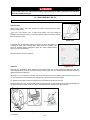
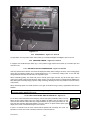
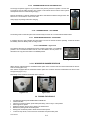
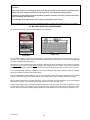
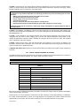
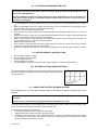
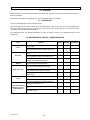
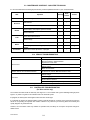
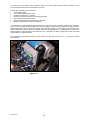
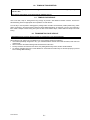
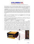
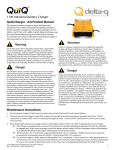
Owner and Operator Manual Summit (SMT) Summit Utility (SUV) Electric Vehicles P/N 712176-02 2012 Summit Preface Welcome, and congratulations on your choice of a vehicle from Columbia ParCar Corp.! Your vehicle has been manufactured in full compliance with all applicable American National Standards Institute (ANSI) standards. Your safe use and operation of your vehicle is important to us. Any alteration of your Columbia ParCar vehicle that results in the vehicle being in noncompliance with applicable ANSI standards is strictly prohibited. Columbia ParCar is not responsible or liable for any damage that results from any such alteration, and all warranties for any such altered vehicles are null and void. Some of the equipment in this manual may not apply to your vehicle, depending on which model you have. To the best knowledge of Columbia ParCar Corp., the material contained herein is accurate as of the date this publication was approved for printing. Columbia ParCar Corp. is not liable for errors in this manual or for incidental or consequential damages that result from the use of the material in this manual. Columbia ParCar Corp. reserves the right to change specifications, equipment or designs at any time without notice and without incurring obligation. This manual contains proprietary information that is protected by copyright. All rights are reserved. No part of this manual may be photocopied, reproduced, or translated to another language without the written consent of Columbia ParCar Corp. Columbia ParCar Corp. products are manufactured under one or more of the following U.S. Patents 2986162, 2987934, 3116089, 3144631, 3144860, 3229792, 3434887, 3559773, 3673359, 3680403, 3683716, 3709317, 4648473, Des. 225626 1115 Commercial Avenue • Reedsburg, WI 53959 Phone: (608) 524-8888 • Fax: (608) 524-8380 (800) 222-4653 • Web: www.parcar.com 2012 Summit i TABLE OF CONTENTS 1.0 INTRODUCTION 1.1 1.2 1.3 1.4 1.5 SAFETY MESSAGES VEHICLE IDENTIFICATION NUMBER 13 DIGIT VIN MATRIX 17 DIGIT VIN MATRIX VEHICLE SPECIFICATIONS 2.0 SAFETY 2.1 2.2 2.3 GETTING STARTED SAFETY GUIDELINES SAFETY VEHICLE STATEMENTS 3.0 OPERATIONS AND CONTROLS 4.2 4.3 4.4 4.5 4.5.3 4.6 4.7 4.8 4.9 4.10 4.11 3.1 3.2 3.3 IMPORTANT FIRST STEP INSPECTING THE VEHICLE VEHICLE CONTROLS 3.3.1 POWER KEYSWITCH 3.3.2 DIRECTION SELECTOR 3.3.3 HIGH/LOW SPEED SWITCH 3.3.4 LIGHT SWITCH 3.3.5 WINDSHIELD WIPER 3.3.6 BATTERY STATE OF CHARGE METER 3.3.7 SYSTEM STATUS LIGHT OPERATING INSTRUCTIONS 3.3.8 WARNING LABEL 3.3.9 3.3.10 ACCELERATOR PEDAL 3.3.11 BRAKE PEDAL 3.3.12 HORN BUTTON 3.3.13 TURN SIGNAL/HAZARD WARNING SWITCH 3.3.14 HAND PARKING BRAKE 3.3.15 CHARGER RECEPTACLE 3.3.16 STEERING WHEEL 3.3.17 HOUR METER INDICATOR 3.3.18 HEATER 3.3.19 WINDSHIELD WASHER RESERVOIR 3.4 PRE-OPERATION CHECKLIST DRIVING THE VEHICLE 3.5 4.0 ELECTRIC SYSTEM 4.1 IMPORTANT INFORMATION BATTERY INSPECTION & MAINTENANCE BATTERY CLEANING CONDITIONS WHICH AFFECT CHARGING DELTA-Q BATTERY CHARGING 4.5.1 CHARGER OPERATING INSTRUCTIONS 4.5.2 RED LIGHT CHARGER ERROR CODES CHECK/CHANGE CHARGING ALGORITHM EXCESSIVELY DISCHARGED BATTERIES SPECIFIC GRAVITY TEST TIPS FOR MAINTAINING YOUR BATTERIES BATTERY REMOVAL AND INSTALLATION BATTERY PACK DISCONNECT METHODS SINGLE POINT BATTERY WATERING SYSTEM 5.0 SERVICING YOUR VEHICLE 5.1 5.2 5.3 5.4 5.5 5.6 5.7 5.8 MAINTENANCE GUIDELINES HYDRAULIC BRAKE SYSTEM BRAKE FLUID MAINTENANCE TIRE CARE WHEEL & TIRE REMOVAL/INSTALLATION CLEANING LUBRICATION MAINTENANCE SCHEDULE - OWNER/OPERATOR MAINTENANCE SCHEDULE - QUALIFIED TECHNICIAN VEHICLE TROUBLESHOOTING CONTROLLER TROUBLESHOOTING 5.9 5.10 5.11 6.0 TOWING & TRANSPORTING 6.1 6.2 TOWING YOUR VEHICLE TRANSPORTING YOUR VEHICLE 7.0 VEHICLE STORAGE 7.1 7.2 7.3 BATTERY PREPARATION VEHICLE PREPARATION RETURNING VEHICLE TO SERVICE NOTICE: In an effort to streamline product support, please ensure your vehicle is properly registered with Columbia ParCar. Registration allows for more effective product support including product updates and warranty processing. Please consult with your servicing dealer to verify or complete the registration process. CHANGE HISTORY DATE DESCRIPTION BY 8/2008 Issued TS 5/2011 Added above notice TS Added remote LED and AC Drive up-date. TS 8/12 2012 Summit ii 1.0 INTRODUCTION This manual provides important safety information, operating instructions, model specifications and maintenance instructions for the vehicle. The information in this manual is limited to care and maintenance information only. Information covering repairs is provided in detailed service manuals available from Columbia Dealers. Such major repairs require the attention of a skilled technician and the use of special tools and equipment. Your Columbia Dealer has the facilities, experience and genuine Columbia parts and accessories to properly service Columbia vehicles. 1.1 SAFETY MESSAGES Safety messages and other information in this manual are preceded by the words DANGER, WARNING, CAUTION or NOTICE. They are printed in bold face, and are very important. We recommend you take special notice of this information. Danger indicates a hazardous situation which, if not avoided, will result in death or serious injury. Warning indicates a hazardous situation which, if not avoided, could result in death or serious injury. Caution indicates a hazardous situation which, if not avoided, could result in minor or moderate injury. NOTICE: Notices are messages not related to personal injury. They will provide key information to prevent property damage and to assure procedures are more easily understood or implemented. 1.2 VEHICLE IDENTIFICATION NUMBER Each vehicle contains a unique Vehicle Identification Number (VIN) which describes facts and features of the vehicle. Summit vehicle can be configured for on road use or off road use. Vehicle with a 13 digit VIN are off road use, Vehicles with a 17 digit VIN are on road use as Neighborhood Electric Vehicles (NEV’s). These vehicles meet the requirements of the National Highway Traffic & Safety Administration (NHTSA) as stated in the Code of Federal Regulations, Title 49, Part 571, Standard 500, Low Speed Vehicles. Vehicle with a 13 digit VIN (non-NEV) will have the VIN labels in two locations. Under the steering wheel cover and on the nameplate located in the driver’s side glove box (Figure 1-2A). Vehicle with a 17 digit VIN (NEV) will have the VIN labels in three locations. Under the steering wheel cover, on the nameplate located in the driver’s side glove box (Figure 1-2A) and on the top of the dash (Figure 12B). NEV vehicle will also have an Operating Restrictions label (Figure 1-2C). This label provides important operation restrictions for neighborhood electric vehicles. Do not remove this label. The nameplate contains important vehicle information such as vehicle weights and maximum load. Read carefully. 2012 Summit 1-1 B C A A Figure 1-2 1.3 13 DIGIT VIN MATRIX Digit 1 – 3 Model S2T = 2-Passenger S4T = 4 Passenger SUS = Short Bed Utility SUL = Long Bed Utility Digit 4 Power Systems E = DC Drive Sep Ex, Regen F = DC Drive Sep Ex, Regen w/ encoder G = AC Drive Induction Motor Digit 5 Voltage/Batteries 4 = 48 Volt (8 – 6 Volt) G = 48 Volt Gel (8 – 6 Volt) - = Standard Product Digit 6 Standard or Special Product # = Special Product 3 = 300 Amp DC Digit 7 Controller Amperage 4 = 400 Amp DC 5 = 500 Amp DC Z = H12: Rear Mechanical Digit 8 Axle/Brake System Y = H12: Rear Hydraulic X = H12: Front & Rear Hydraulic Digit 9 Year Built L = 2012, M = 2013, N = 2014, etc. Digits 10 – 13 Build Sequence 0000 Through 9999 2012 Summit 1-2 1.4 17 DIGIT VIN MATRIX Digit 1 – 3 Mfg. ID 5FC = Columbia ParCar Digit 4 Vehicle Type L = Low Speed Vehicle Digit 5 Series S = Summit 2 = Two Person 3 = Long Bed 4 = Four person 5 = Short Bed Digit 6 Body Type Digit 7 Engine Type 6 = 48 Volt DC Drive 8 = 48 Volt AC Induction Drive Digit 8 Restraint A = Type 1 Seat Belt Assembly B = Type 2 Seat Belt Assembly (3 point) Digit 9 Assigned Check Digit Digit 10 Model Year B = 2011, C = 2012, D = 2013 etc. Digit 11 Plant Location 1 = Reedsburg Digit 12 - 17 123456 = Build Sequence To ensure prompt service when repairs or adjustments are required, your Columbia Dealer must have the VIN. An example of a current 13 digit VIN is SUSEB-4YL1234 An example of a current 17 digit VIN is 5FCLS36A681123456. For your own personal reference, fill in the VIN in the space provided below: 1.5 VEHICLE SPECIFICATIONS SM-2 SM4 SUV-S SUV-L 19 mph non-NEV 25 mph NEV Max. Speed Max. Range* Up to 40 miles Up to 35 miles Up to 40 miles Up to 35 miles Passenger 2 4 2 2 Power 48 Volt DC Drive Standard, 48 Volt AC Drive Optional Brakes Hydraulic rear drums, Hand parking brake Overall L x W x H (Inches) 99 x 48 x 72 124 x 48 x 72 107 x 48 x 72 131 x 48 x 72 Wheelbase 66 92 76 91 Flat Bed (inches) - - 36 x44 60 x 44 Curb Weight (lbs) 1500 1780 1600 1750 Gross Vehicle Weight (lbs) 2090 2550 2338 2735 Ground Clearance (Inches) 5.5 Lighting – Non-NEV do not have all listed Headlights, Taillights, Brake Lights, Back-up Lights, Emergency Flashers, Reflectors, License Plate, Turn Signals Windshield/Mirrors Safety Glass Windshield, Rear & Side Mirrors Charger Built-in, micro-processor controlled with remote LED Battery Eight, 6 volt 2012 Summit 1-3 2.0 SAFETY 2.1 GETTING STARTED For personal safety before operating the vehicle, it is the operator’s responsibility to read, understand and follow the basic rules of operation and maintenance instructions in this manual. If you are responsible for the use of the vehicle, it is your responsibility to inform the person or persons using the vehicle about the following basic rules of operation for their personal safety. It is Columbia ParCar Corporation’s specific recommendation that the following warnings must be observed at all times. Not all are repeated throughout this manual, but the recommendations included must be observed whenever these subjects (vehicle operation hazards, battery hazards, etc.) are encountered. Be a safe operator. Electric vehicles are only as safe as the person who is at the controls. If accidents are to be prevented, and they most certainly can be prevented, operators must accept their full measure of responsibility. While the designer, the manufacturer and the safety engineer can help minimize the possibility of an accident, their combined efforts can be erased by a single careless act. 2.2 SAFETY GUIDELINES Observe the following guidelines for safe operation. Define where vehicles may be driven. Define who should be allowed to drive the vehicle. Instruct first-time drivers. Maintain vehicles in a safe driving condition. Enforce safe-driving rules. 2.3 SAFETY VEHICLE STATEMENTS This vehicle will not provide protection from lightning, flying objects, or other storm related hazards. If driving the vehicle in a storm, leave the vehicle and take shelter as per safety guidelines for your location. Failure to maintain the vehicle properly or any modifications or changes that affect the stability, steering or that results in increased speed beyond factory specifications could result in vehicle damage, severe personal injury or death. 2012 Summit 2-1 Follow all procedures exactly and observe all safety messages stated in this manual. Working on vehicles without following proper procedures and using proper equipment may result in vehicle damage or personal injury. Do not attempt to service hot motor or components. Failure to observe this warning could result in severe burns. Always wear safety glasses or approved eye protection while servicing vehicle. If any problems are found during scheduled maintenance or inspections, do not operate vehicle until repairs are made. For personal safety and to maintain stability and control, operate this vehicle under these conditions only. Failure to comply with these warnings may result in bodily injury and property damage. All vehicles should be operated from the driver’s side by authorized persons. Never exceed the maximum load capacity ratings of the vehicle. Exceeding these limits may endanger occupants. Personal injury may result if body parts (arms, head, and legs) are not kept inside vehicle while moving. Do not start moving until all occupants are seated. Remain seated and hold on while vehicle is in motion. Before leaving your seat, completely stop vehicle and lock parking brake. If vehicle is to be left unattended, turn keyswitch to “OFF” and remove key. Do not use accelerator to hold vehicle on an incline. Use brake. Make sure directional keyswitch is in position for the desired direction of travel before depressing the accelerator. Do not change the directional keyswitch while vehicle is moving. Drive slowly in turns and up and down grades. Do not make turns on steep hills or inclines. Do not operate while under the influence of alcohol or drugs. To avoid the risk of injury or vehicle damage, operate at maximum speed only on smooth flat surfaces. Allow additional stopping distance when traveling at higher speeds. These basic rules of operation, combined with courtesy and common sense, will help make driving your Columbia vehicle a safe and pleasant experience. Use only genuine Columbia vehicle replacement parts. No modifications or additions, which affect the mechanical or electrical integrity and the safe operation of the unit, shall be made without the written approval of the manufacturer. If in doubt about any modification, contact your local Columbia Dealer or Columbia ParCar Corp. Customer Service. 2012 Summit 2-2 3.0 OPERATIONS AND CONTROLS 3.1 IMPORTANT FIRST STEP Upon initial delivery, it is very important that the battery pack is properly charged. This is required if the vehicle is to be stored for later use or is to be used immediately. Check that the batteries are not damaged or leaking and that connections are tight. Remove the battery vent caps and inspect each cell for proper electrolyte level. If the electrolyte level is below the plates add only enough water to cover the plates. See Section 4.2. For sealed batteries, do NOT attempt to remove caps or open vents. See Section 4.2. NOTICE: Do not overfill a cell. Electrolyte expands and can overflow during charging. With the electrolyte level correct, use the on board Delta-Q Charger to charge the batteries as described in Section 4.5.1. Charging is complete when the Delta-Q green 100% charge LED lights. Vehicles without a single point watering system, refill cells to below the bottom of the each cell vents. See Figure 4.2.2. Vehicles with a single point watering system will require completion of 4 to 5 charge cycles before watering. NOTICE: If the vehicle is not going to be used the Delta-Q Charger can remain connected to an AC source. It has the capability to test and recharge the battery pack during storage. 3.2 INSPECTING THE VEHICLE After battery charging, perform a pre-delivery inspection of the vehicle. Also, before using the vehicle, there are checks that must be performed to ensure that it is in safe proper working order. NOTICE: Vehicle should be inspected immediately after delivery. Use the following guidelines to make sure there are no obvious problems. Examine the contents of all packages and accessories that may have come in separate packages with this vehicle. Make sure everything listed on the packing slip is there. Items should not be broken or damaged. Examine any visible wiring for obvious signs of damage. Check that all connections are secure. Inspect the tires for obvious wear or damage. Check for proper tire inflation. Refer to manufactures recommendation imprinted on tire sidewall. Make sure that all wheel lugs are secure. Check the body, seats, trim and other external parts for obvious damage. Look for body damage, jagged edges etc. that may cause personal injury. Operate each of the following controls before turning on the power keyswitch. Accelerator Pedal for smooth operation. Braking Pedal, assure presence of a firm pedal with minimal travel. Steering, check for responsiveness and little play. Key can only be removed when keyswitch in “OFF” position. NOTICE: Each control should operate smoothly and easily without sticking or requiring excessive effort. Horn, check for proper operation. Check that the warning buzzer sounds in reverse. Head lights, brake and tail lights, emergency flasher operating. Directional selector switch, check for proper operation. If vehicle has just been delivered, report any physical damage or missing items to the shipping company and your local Columbia Dealer. Report any battery or service issue problems to the individual(s) responsible for correction and/or repair or contact your local Columbia Dealer for service. 2012 Summit 3-1 If any problems are found, Do not operate vehicle until repairs are made. Failure to make necessary repairs could result in fire, severe personal injury, property damage or death. Consult your local Columbia Dealer for professional service. 3.3 SEATS AND SEAT BELTS NOTICE: Adjust seat before driving. After adjustment, make sure seat is secure. Adjusting Seat Adjust driver’s seat to allow easy operation of pedals, steering wheel and driver controls on dashboard. Figure 3.3.1 is the driver’s seat. To adjust seat position, move the handle (A) sideways and select seat position. To access batteries, adjust the seat fully forward, then lift release lever (B). B A Figure 3.3.1 If equipped with non-adjustable seating, the seats may still be adjusted by remounting the seats at the mounting plate. Remove the four mounting bolts, select the preferred seating arrangement using AFT, MID or FORE position (Figure 3-2), and reinstall bolts. Tilt seat forward for access to batteries. Figure 3.3.2 Seat Belts Seat belts are self-adjusting. When attaching the seat belt, ensure that you are leaning back against the seat. The chest strap should be as close as possible, without restricting the neck. The abdominal strap should be placed flat against the thighs and abdomen. See Figure 3.3.3. To fasten the seat belt, pull out the belt slowly and without pause, push buckle into lock (C) until you hear a light click. If the belt binds when pulling it out, release the belt and pull out again. To unfasten the seat belt, push on the red button (D) and release the buckle from the lock. When the belt is not in use, the belt buckle must be positioned near the wall mounting clip (E) with the adjustable clip (F). When leaving the vehicle, make sure belt is in proper position to avoid belt jamming in the door. E 3-1 D F C Figure 3.3.3 2012 Summit 3-2 Seat belts must be worn at all times when the vehicle is in motion. Follow all local safety seat belt laws. Important Seat Belt Information The seat belt is designed to hold one person. Never place a child on your knees and attach seat belt. Never use a device that interferes with the seat belt as there is a greater risk of injury in an accident if the seat belt is too loose. Following a serious accident, the seat belts in use at the time must be replaced. If any seat belt is faulty or damaged, it must be replaced immediately. If it is necessary to clean the seat belts, use only soap and water. The use of any other cleaning agents is prohibited. Improperly adjusted seat belts may cause injury in an accident. Pregnant women must wear a seat belt. Adjust the abdominal strap to avoid putting too much pressure on the abdomen. Do not attach abdominal strap under the arm or behind the back. When wearing seat belt, make sure strap is not twisted. The seat belts were designed for use by occupants of adult height. Do not modify or alter the seat belt, its attachment to the vehicle or the seats. Only use the manufacturer original equipment seat belts. Babies and infants should never be transported on the knees of a vehicle occupant. It is particularly dangerous to strap in a child while he/she is seated on your knees. Never use one seat belt for more than one person at a time. Child seats are not recommended for this vehicle. It is imperative to follow local laws where driving, particularly in respect to driving with children of specific ages in the front seats of the vehicle. 3.3 VEHICLE CONTROLS This section describes the operating controls of the vehicle. Figure 3.3.1 identifies many of these controls. Figure 3.3.1 is for a DC Drive vehicle. 3.3.1 POWER KEYSWITCH – Figure 3.3.1 Arrow A With the power keyswitch in “OFF” position, the Traction System is powered down. This conserves battery energy by reducing the power draw when vehicle is not in use. Turning the power keyswitch to OFF is highly recommended whenever vehicle is not in use. Always take the key out of the keyswitch when leaving the vehicle. 3.3.2 DIRECTION SELECTOR – Figure 3.3.1 Arrow B When the direction selector is in the vertical position, the vehicle’s direction signal is turned OFF or in neutral. Turn direction selector to the right from vertical position to move the vehicle in forward direction. Turn direction selector to the left from vertical position to move the vehicle in reverse direction. A warning buzzer sounds when in reverse. NOTICE: Direction selector must be in the N or neutral position prior to turning on the ACEplus or Smartdrive power keyswitch, or a reset of the direction selector to neutral will be required before traction drive is enabled. See Section 5.11 CONTROLLER TROUBLESHOOTING. 3.3.3 HIGH/LOW SPEED SWITCH – Figure 3.3.1 Arrow C Used only on DC drive vehicle. This switch is a two-position toggle switch. The up position (rabbit) is for high speed and allows the vehicle to reach full speed. The down position (turtle) is a slower speed and is used for steep grades or off road in rough terrain. This switch is not in operation when the vehicle is in reverse. 2012 Summit 3-3 H G I F A B C D E K J Figure 3.3.1 3.3.4 LIGHT SWITCH – Figure 3.3.1 Arrow D The light switch is a two-position switch. Move switch up to activate headlights and taillights, down to turn off. 3.3.5 WINDSHIELD WIPER – Figure 3.3.1 Arrow E If equipped, the windshield wiper switch (E) is a two-position toggle switch. Move switch up to activate wiper and down to turn off. 3.3.6 BATTERY STATE OF CHARGE METER – Figure 3.3.1 Arrow F Used only with DC Drive vehicles. This meter will display the battery state of charge. As shown, it is an analog gauge meter with an indicating needle and a colored background. It is a continuously reading meter. At rest with fully charged batteries the meter should read in the right white region. When accelerating quickly, the needle will move to the left green region near the very far left red region. This is normal. If the needle continues past the green region into the very far left red region, it indicates that the batteries are 80% discharged or basically empty (only 20% charge remaining). Recharge as soon as possible to avoid a shut-down of the vehicle. When decreasing speed, the needle will move to the right as electrical energy is being “regenerated” back into the batteries. NOTICE: At 80% discharge, you must immediately charge batteries or vehicle operation will cease and permanent battery damage could occur. 3.3.6A MULTI-FUNCTIONAL DISPLAY INDICATOR – Figure 3.3.2 For AC Drive vehicle this Multi-functional Display Indicator will replace the Battery State of Charge Meter and the System Status Light. This meter will display the battery state of charge, an hour meter and the controller status. With fully charged batteries, the uppermost green LED is lit. A lit lower red LED indicates discharged batteries. The hour meter is an alpha-numeric liquid crystal display in the center of the MDI showing the hours worked. If there is a controller error the hours worked will be replaced with a flashing error code. It is important to note the error code. It will aid a technician in corrective actions. 2012 Summit 3-5 Figure 3.3.2 3.3.7 SYSTEM STATUS LIGHT – Figure 3.3.1 Arrow G Used only with DC Drive vehicles. The green system status LED will light when the power keyswitch is turned to the “ON” position. This indicates the controller is powered up and should display a steady green light. With the power keyswitch “ON”, if this green status light is not lit or is flashing refer to Section 5.11 CONTROLLER TROUBLESHOOTING. 3.3.8 OPERATING INSTRUCTION - Figure 3.3.1 Arrow H Read carefully before operating the vehicle. Promptly replace if removed or damaged. Contact Columbia ParCar for replacements if needed. 3.3.9 WARNING LABEL - Figure 3.3.1 Arrow I Read carefully before operating the vehicle. Promptly replace if removed or damaged. Contact Columbia ParCar for replacements if needed. 3.3.10 ACCELERATOR PEDAL – Figure 3.3.1 Arrow J This pedal controls the speed of the vehicle in the same manner as a conventional automobile. The pedal must be fully released when changing directions. If not fully released, a reset of the power system or direction selector is required. To avoid injury, speed in reverse should always be kept at a minimum. 3.3.11 BRAKE PEDAL – Figure 3.3.1 Arrow K Pressing the brake pedal activates brake lights and will slow or stop the vehicle. NOTICE: Never rest your foot on brake pedal while operating the vehicle. This wears brake pads, creates drag and causes excess battery discharge. 3.3.12 HORN BUTTON – Figure 3.3.3 Arrow L The horn button (Arrow L) is located on the left side of the steering column, below the turn signals. 3.3.13 TURN SIGNAL/HAZARD WARNING SWITCH – Figure 3.3.3 The turn signal/hazard warning switch is located on the left side of the steering column. When lever (Arrow M) is moved upward the right turn signal turns on. When lever is moved downward the left turn signal turns on. To turn off a signal move indicator lever back to center position. To operate the hazard warning lights pull outward on hazard bar (Arrow N). Moving the signal indicator lever to either of the turn signal positions will turn off the hazard lights. M L N Figure 3.3.3 3.3.14 HAND PARKING BRAKE – Figure 3.3.4 Arrow O To lock the brake, pull the brake lever upward. To release, depress the button at the end of the handle and let the handle down to the original position. Always apply parking brake when leaving the vehicle. NOTICE: Do not operate the vehicle with the hand parking brake applied. Damage to the vehicle could result. 2012 Summit 3-7 3.3.15 CHARGER RECEPTACLE AND REMOTE LED The charger receptacle (Figure 3.3.4) is located on the panel by the driver’s position. The AC cord is plugged in here for battery charging. The charger is inter-locked with the traction control system which powers down the vehicle during charging. Near the receptacle is a remote multicolored LED which will indicate the Delta Q charge status. See Section 4.5.1 for information on the remote LED. Always apply the parking brake when charging. NOTICE: Before removing the AC cord, be sure to check the Delta-Q status lights. Figure 3.3.4 3.3.16 STEERING WHEEL – NOT SHOWN The steering wheel controls the path of the vehicle exactly the same as a conventional automobile wheel. 3.3.17 HOUR METER INDICATOR – NOT SHOWN If equipped, the hour meter indicates the total number of hours the vehicle has been operating. It would be located immediately below the Battery State of Charge meter. 3.3.18 CAB HEATER – Figure 3.3.5 The optional cab heater is equipped with a three position toggle switch. The CENTER position is off. To activate the heater and fan, move the switch to the UP position. To activate the fan only place the switch in the DOWN position. Figure 3.3.5 3.3.19 WINDSHIELD WASHER RESERVOIR SMT4 vehicles equipped with the windshield washer option have a washer reservoir located underneath the driver’s side rear seat (Figure 3.3.6). SUV vehicles equipped with the windshield washer option have a washer reservoir located behind the driver’s side storage area (Figure 3.3.7). Periodically check and fill the windshield washer reservoir. Figure 3.3.6 Figure 3.3.7 3.4 DRIVING THE VEHICLE Complete the following PRE-OPERATION CHECKLIST. Fasten seat belts. Insert key in power keyswitch, press brake pedal firmly, and turn key to "ON" position. Select high or low speed. Switch the direction selector to the direction of desired travel. Release the parking brake and brake pedal. Slowly press accelerator pedal to obtain desired vehicle speed. To slow or stop vehicle, remove foot from accelerator and press brake pedal. 2012 Summit 3-8 3.5 PRE-OPERATION CHECKLIST Should any item malfunction or need adjustment, do not operate vehicle until the problem has been corrected. ITEM PROCEDURE Fully charged or adequately charged to provide power for duration of operations. The AC cord is disconnected from the vehicle. Electrolyte level in each cell covers the top of cell plates. Batteries (See Section 4.10 if vehicle is equipped with a Single Point Battery Watering System.) Batteries are secure and free of corrosion. All terminals and connections are tight. Tire Pressure Inflated to recommendation per Section 1.4. Do not exceed maximum stated on tire sidewall. Turn lights on and make sure they illuminate. Lights, Horn and Reverse Buzzer Check brake/tail lights and turn signals. Reverse buzzer operating. Press horn button to sound horn. Pedal has firm pedal pressure with minimal travel. Brakes Parking brake has proper engagement and release. Steering Responsiveness and the absence of excessive free play. Obstacles Path of intended travel is free from obstructions. Seat Belts Driver and passenger are secured by seatbelts before moving vehicle. Labels Accelerator 2012 Summit All warning and operation labels in place. Check for smooth operation. 3-10 4.0 ELECTRIC SYSTEM 4.1 IMPORTANT INFORMATION The type of battery used in a Columbia vehicle has a service requirement which is quite different from that of an automotive battery. The electric vehicle battery supplies all of the power to drive the vehicle. During operation the power stored in the batteries is expended. While the amperage drain rate can vary greatly depending on the type of service, the duration of use and the number of "starts" and "stops" made during a day, the batteries nevertheless progress through each duty cycle from "fully charged" to an almost depleted state. This type of service is known as "deep cycle" service and electric vehicle batteries are specifically designed to handle this type of service. Proper performance of your Columbia vehicle can only be obtained from specified deep cycle, electric vehicle batteries. PLEASE REVIEW IMPORTANT DANGER, AND WARNING STATEMENTS WHEN WORKING AROUND BATTERIES AND CHARGING SYSTEMS! Always remove key and disconnect battery pack before servicing or repairing the vehicle. See Section 2.4. Always wear full-face shield when working on or near batteries. All batteries used in electric vehicles can explode! Batteries produce explosive hydrogen gas at all times, especially, during charging or discharging. Ventilate area when charging batteries. Do not attempt to charge a battery if it is frozen, or if the case is bulged excessively. Frozen batteries can explode! Properly dispose of the battery. Do not smoke around batteries. Keep sparks and flames away from batteries and the charging area. Use care to prevent an accidental arc which could cause an explosion. Use only approved insulated tools, remove jewelry such as rings, watches, chains etc. and place an insulating material (wood, plastic, rubber etc.) over all battery connections. Never add acid to a battery. Battery acid is poisonous and can cause severe burns. Avoid contact with skin, eyes, or clothing. ANTIDOTES: EXTERNAL: Flush with water. Call a physician immediately. INTERNAL: Drink large quantities of milk or water. Follow with milk of magnesia or vegetable oil. Call a physician immediately. EYES: Flush with water for fifteen minutes. Call physician immediately. To reduce the risk of electrical shock or injury: Do not use an ungrounded two to three-prong adapter to connect the charger to a two-prong outlet or extension cord. The battery charger must be properly grounded. Use a three prong No. 12 AWG heavy duty power cord with a ground conductor in good condition. Keep it as short as possible. No more than 50 feet. Locate all cords so that they will not be stepped on, tripped on, or otherwise damaged. Immediately replace worn, cut, or damaged power cords or wires. Do not connect the power cord near fuels, grain dust, solvents, thinners, or other flammables. The spark can ignite flammable materials and vapors. 2012 Summit 4-1 NOTICE: Automotive batteries should never be used for "deep cycle" application, as their useful life will be very short. Install surge arrestors on incoming AC power lines. Surge arrestors will help protect electrical/electronic components in the charger and vehicle from all but direct or “close proximity” lightning strikes. Damaged or corroded battery terminals should be replaced or cleaned as necessary. Failure to do so may cause overheating during operation. Do not attempt to recharge batteries with a charger not designed for your vehicle. Only trained technicians should service the Delta Q charger. Contact your Columbia Dealer for assistance. 4.2 BATTERY INSPECTION & MAINTENANCE Do not attempt to remove caps from sealed batteries. See Figure 4.2.1 Figure 4.2.2 Figure 4.2.1 For non-sealed batteries, check the electrolyte level on new batteries before they are put into service, and, at a minimum, once a week thereafter. Water use increases as batteries age. (See Section 4.11 if vehicle is equipped with a Single Point Battery Watering System.) See Figure 4.2.2. Never allow the electrolyte level (A) to fall below the top of the plates (C). If the plates are exposed, add only enough to cover the plates before charging. After batteries are fully charged, fill cells to just below the bottom of the cell vents (B), approximately 1/8” to 1/4”. Electrolyte level should not touch the bottom of the cell vents. Do not overfill batteries. Electrolyte expands and can overflow during charging. Water added to replace the spillage dilutes the electrolyte and reduces its specific gravity. Use only distilled water. Vehicle batteries may use up to 16 quarts of water during their useful life and non-distilled water may contain harmful minerals which will have a cumulative adverse effect on battery performance and life. Be sure battery hold downs are properly tightened. A loose hold down may allow the battery to become damaged from vibration or jarring. A hold down that is too tight may buckle or crack the battery case. Weekly inspect battery posts, clamps and cables for breakage, loose connections and corrosion. Replace any that are damaged. Check to see that battery cap vent holes are clear. Plugged vent holes will not permit gas to escape from the cell and could result in battery damage. Batteries and connections must be clean and dry. See Section 4.3. 2012 Summit 4-2 Weekly an equalization charge is to be applied to the battery pack. This process balances the electrical charge in the battery pack and will extend battery life. The following procedure is used to complete this. Charge the battery pack allowing the Delta-Q Charger to go to green 100% charge. Once the green LED lights unplug the power cord. Wait approximately 30 seconds. Reconnect the power cord and allow the Delta-Q to complete a second charge cycle. If the vehicle is not to be used, leave power cord connected. The Delta-Q can test and recharge as needed. 4.3 BATTERY CLEANING Acid-soaked debris on the battery terminal connections will cause current leakage, reduces battery efficiency, and battery life. Check that all vent caps are tightly in place. Hose wash battery terminal connections periodically with clean lowpressure water to keep them free of acid spillage, dirt, and other debris. Do not hose wash electronic controllers, switches, solenoids and other electrical control devices. Cover as necessary to prevent splashing. Clean battery terminal connections with baking soda (sodium bicarbonate) and water solution. Mix 5 teaspoons baking soda per quart of water. Use a stiff bristle brush, rinse with clean water and dry with a clean cloth. Do not allow solution to enter cap vent holes. NOTICE: Follow local ordinances and codes for proper disposal of battery cleaning waste. 4.4 CONDITIONS WHICH AFFECT CHARGING Always schedule enough charging time so the Delta-Q Charger attains the 100% level. Charging time is affected by age and battery condition, state of discharge, electrolyte temperature, AC line voltage, and other variables. Correct charging methods extend battery life and vehicle range between charges. New batteries need up to four hours more charging than “mature” batteries. Before the first use, completely charge new batteries. Charging time will vary based on conditions noted above but will probably be 12 hours. If vehicle is used only occasionally, a refresher charge should be given prior to using. Battery efficiency is affected by temperature. If the temperature of the outside air and/or batteries is below 60º F, battery capacity is reduced. Batteries will require more frequent and longer charge periods in early spring, fall and winter. As batteries age, they finish charge at progressively higher charge rates and tend to use more distilled water. At this point in battery age, charger will automatically begin reducing charge time. Batteries found defective must be replaced. All batteries in a vehicle should be matched according to age, capacity and brand. 4.5 DELTA-Q BATTERY CHARGING All current production Columbia 24/36/48 volt electric vehicles are built with a new solid state on-board, fully automatic Delta-Q Battery Charger (Figure 4.5.1) as standard equipment. This section explains in more detail the Delta-Q Charger Operations. The Delta Q charge status can be found in two locations. On the Delta Q face and on a remote multicolored LED (Figure 4-5.2). This LED and descriptive label will located near the Charger Receptacle. 4-4 Figure 4.5.1 Figure 4.5.2 2012 Summit 4-3 NOTICE: Do not cover the charger cabinet or cooling fins with clothing, blankets, or other material. Fins provide ventilation and prevent overheating. Do not disassemble the charger. There are no serviceable components. 4.5.1 CHARGER OPERATING INSTRUCTIONS Connect the supplied power cord to the vehicle charger receptacle and to a properly grounded wall outlet. Charger start and charge time is automatic. The Yellow AC power LED (Fig. 4.5.1 No. 1) should remain illuminated while the Charger is plugged into an AC source. The remote LED will be flashing short green. If these LED’s are not lit, before replacing Charger, recheck the AC connection and the AC source fuse or breaker. If this fails to correct the problem, contact your Columbia Dealer for assistance. Charger will automatically turn on and conduct a short self-test and battery test. All Delta Q LED’s will flash in sequence and then a trickle current will be applied to batteries until a minimum voltage is reached. In Figure 4.5.1 No. 3 indicates the Bar Graph and No. 2 indicates the lowest LED. Three (3) amperes is displayed as the lowest LED on the Bar Graph. If the batteries meet the minimum voltage requirements of the Charger, signifying they are serviceable (chargeable), the Charger enters the bulk charging (higher amperage-constant current) stage. The Bar Graph LED’s indicate the electrical current being delivered to the batteries as the Charger moves through its automatic charge profile. The length of charge time at each level will vary due to battery size and battery charge depletion. The remote LED will be flashing short green. NOTICE: If the batteries are excessively discharged, the Delta-Q Charger will not be able to charge the complete set of batteries. The Delta-Q RED FAULT LED (Fig. 4.5.1 No. 6) and the remote LED will be flashing red. (See Section 4.5.2 Red Light Charger Error Codes). It will then be necessary to follow the Special Charging for Excessively Discharged Batteries, Section 4.6. When the Yellow 80% LED (Fig 4.5.1 No. 4) is lit, the Charger has completed the bulk stage and the batteries are at approximately 80% state of charge. The 80% LED remains on as the last 20% of charge is returned to the batteries in the second phase (constant voltage phase). At this time the remote LED will flash long green. NOTICE: You can terminate charging at this point if necessary. The vehicle can be used, but completing the charge cycle is highly recommended. Repeated “Short Charging” leaving the charge short of 100% will shorten operating cycle distance and reduced battery life. A low current “finish-charge” phase returns and maintains batteries to maximum capacity. The 100% Green LED’s will blink until “finish charge” phase is complete. A 100% Green LED continuously lit indicates the batteries are completely charged. The Charger may now be unplugged from the AC source. If the batteries will not be used for a length of time, check monthly for the charge level. It is also acceptable to leave the Charger plugged in. The Delta-Q has the capability to test and recharge if necessary. A fault occurring while charging causes the RED FAULT LED and the remote LED to flash with a code relaying the error. Some errors may require repair by a qualified technician and others may be simply transient and will automatically recover when the fault condition is eliminated and the Delta-Q cycled by disconnecting the AC source for a minimum of 11 seconds. NOTICE: A Yellow (Amber) flashing LED in the upper Bar Graph (Fig. 4.5.1 No. 3) and a flashing yellow remote LED indicates the thermostatic control has limited the Charger output due to ambient temperature conditions. It is still charging, but at a reduced rate. 4.5.2 RED LIGHT CHARGER ERROR CODES 1 FLASH = Battery Voltage High: Auto-recover. May be temporary condition, or wrong Charger installed, i.e. 36 volt Charger on 48 volt battery pack. 2 FLASH = Battery Voltage Low: Auto-recover. Confirm each individual batteries minimum voltage with a voltmeter. Two or more 6 volt batteries register less than 5.85 volts, or accumulative total pack voltage has been discharged to less than 20% remaining. Vehicle operation will cease until batteries are recharged. See EXCESSIVELY DISCHARGED BATTERIES Section 4.6. 2012 Summit 4-4 3 FLASH = Charge Timeout: The charging did not complete in allowed time, 12-14 hours. This may indicate a battery problem, or that the Charger output was reduced due to high ambient temperatures. Disconnect AC supply, confirm sufficient ventilation, allow cool down time, and restart Charger. NOTICE: If the Delta-Q is exhibiting a 3 flash fault and it has been determined that the cause was not due to ventilation or high ambient temperature, the following procedure may restore the battery pack to normal operation. Battery posts and terminals must be clean and free of corrosion. Check that electrolyte level just covers plates. Plug in charger for at least a 16 hour charge. Check and fill electrolyte. Drive the vehicle for less than half the distance normally driven. Repeat the above steps until the Delta-Q goes green 100% charge on a 16 hour charge. If repeated cycles (5-7) do not result in a 100% green charge, the batteries are beyond useful life and will need replacement. 4 FLASH = Check Battery: The batteries could not be trickle charged up to a minimum level to start Charger. This may be the result of badly discharged batteries, or one (or more) damaged cells. See EXCESSIVELY DISCHARGED BATTERIES Section 4.6. 5 FLASH = Over-Temperature: The Charger shutdown due to high internal temperature. May require reset (AC unplugged) and cool down to restart charging cycle. This fault may indicate inadequate cooling airflow or high ambient air temperatures. Check for debris or blockage at cooling fins. Move the vehicle to a cooler, well ventilated area, or adjust time of day when charging. 6 FLASH = Delta-Q Charger Fault: A fault was detected either in the batteries or in the Charger. The batteries must be tested to ensure there is no damage to one or more cells. If the batteries are found to be good, the Charger may need to be replaced by a qualified technician. A STEADY RED FAULT LED confirms an internal electrical fault of the Delta-Q and requires Charger replacement and return. 4.5.3 CHECK / CHANGE CHARGING ALGORITHM The Delta-Q Charger has been programmed for use with the Columbia ParCar supplied batteries and contains ten algorithms for use with different batteries. The Table 2 details these battery models. NOTICE: For maximum battery life the correct algorithm must be used. NOTICE: If your battery model is not listed in Table A, contact Delta-Q for further information. TABLE A ALGORITHM # BATTERY TYPE 43 Discovery 200-400 Ah AGM 37 Trojan T105 DV/DT CP – 42V pack w/ 48V Charger 27 Crown CR-325 8 Concorde 10xAh AGM 7 J305 DV/DT CP 6 DEKA 8G31 Gel 5 Trojan 30/31XHS 4 US Battery US 2200 (Standard) 3 T105 DV/DT CP 1 Trojan T105 Each time AC power is applied with the battery pack NOT connected, the charger enters an algorithm select/display mode for approximately 11 seconds. During this time, the current algorithm # is indicated on the 80% LED light. A single digit algorithm # is indicated by the number of blinks separated by a pause. A two digit algorithm # is indicated by the number of blinks for the first digit followed by a short pause, then the number of blinks for the second digit followed by a longer pause. 2012 Summit 4-5 To check/change the charging algorithm: Disconnect the charger positive connector from battery pack. Apply AC power and after the LED test, the algorithm # will be displayed for 11 seconds. To change the algorithm, touch the positive connector during the 11 second display period to the battery pack’s positive terminal for 3 seconds and then remove. The algorithm # will advance after 3 seconds. Repeat until the desired algorithm # is displayed. A 30 second timeout is extended for every increment. Incrementing beyond the last algorithm moves back to the first algorithm. After the desired algorithm # is displayed touch the charger connector to the battery positive until the output relay is heard to click (~ 10 seconds). The algorithm is now in permanent memory. Remove AC power from the charger and reconnect the charger positive connector to the battery pack. It is highly recommended to check a newly changed algorithm by repeating the above steps. 4.6 EXCESSIVELY DISCHARGED BATTERIES NOTICE: Columbia Dealer will have the equipment and experience to perform the following battery inspections. The Delta Q will not charge dead batteries. First establish that none of the batteries have an internal fault or bad cell. If a battery has remained too long in a discharged state (i.e. 2-4 volts each), it may be internally damaged and not capable of accepting a charge and must be replaced. If the electrolyte Specific Gravity is low (less than 1.1098 SG) or individual battery voltage is les than 5.25 volts for three cells (10.5 volts for six cells), recharge each battery with an ordinary automotive style trickle charger at a rate of 3 to 6 amps. It is not necessary to disconnect the battery cables, as the alligator style clips can be connected to each positive and negative battery post. Follow specific Charger instructions. To prevent a spark from igniting the gas emitted from the batteries, always disconnect the Charger AC power cord first when moving the positive/negative alligator clips. Be sure to charge all of the batteries in the set. Each battery may require two to three hours of charging to bring it back to serviceable condition. After all batteries have been individually charged, remove the automotive Charger and restart charging with the Delta-Q Charger (Section 4.5.1). It may require several 8-12 hour cycles for bring severely discharged batteries back to 100% charged condition. If again the Delta-Q Charger has the RED FAULT LED (Fig. 4.5.1 No. 6) flashing there is a problem with one or more of the batteries. 4.7 SPECIFIC GRAVITY TEST It is possible to determine a battery's ability to perform by measuring the specific gravity (sp. gr.) of each cell with a hydrometer. This is the best method to determine a defective battery. The hydrometer readings indicate two things: State of Charge - The amount of electrical power stored in the battery. Condition - The ability of battery to store and deliver power. NOTICE: Batteries should be fully charged before performing specific gravity tests to determine battery condition. Hydrometer tests of batteries not fully charged are misleading and inconclusive. There are different type hydrometers. Carefully read and follow the instructions supplied with your hydrometer. NOTICE: Specific gravity readings are at 800F. Values need adjustment for electrolyte temperature. Reduce .004 for every 100F below 800F. Increase by that amount for every 100F above. 2012 Summit 4-6 4.8 TIPS FOR PROLONGING BATTERY LIFE NOTICE: A common misconception is Deep Cycle Batteries develop a memory, lose capacity, or must be discharged until the BDI warning flashes and then recharged. Deep Cycle Wet Lead Acid Batteries are not like cell phone NiCad Batteries. Deep Cycle Batteries benefit from frequent charging and being maintained at as close as possible to a 100% state of charge. Plugging in the Delta Q Charger overnight or when the vehicle is not in use for 3-5 or more days is encouraged. To prolong battery life, recharge batteries as soon as they become 20% or more discharged (less than 1.238 sp. gr.). Make it a regular habit to plug in the charger when the vehicle is not in use. Batteries may be recharged if vehicle has been driven 15 minutes or more since the previous charge. Make sure your electrical outlet is operational. Never go below 20% state of charge (or 80% discharged) without recharging immediately. Allow 14 – 16 hours of charging. Batteries will provide a longer life if not deeply discharged. Batteries that are regularly deeply discharged will require more work by the charger and will have a shorter life. Make it a regular habit to check (and water) your batteries after charging. Always add water after charging. This will reduce the chance for overflow due to expanding water. Weekly equalize the battery pack. If the vehicle is not operated daily the Power keyswitch should be turned off. This will power down the traction control system and reduces power loss on the batteries. Batteries in storage may self discharge and should be recharged when the specific gravity falls below 1.238 sp. gr. 4.9 BATTERY REMOVAL & INSTALLATION Remove battery negative (-) cables. Remove battery positive (+) cables. Remove battery hold down. Remove batteries from vehicle. To install batteries, reverse the removal procedure with the negative (-) cables being attached last. 4.10 BATTERY PACK DISCONNECT METHODS The following illustrates the battery pack configuration. Disconnect both battery leads from the battery pack (Main Solenoid and Controller B-) before performing any vehicle service. 4.11 SINGLE POINT BATTERY WATERING SYSTEM When equipped, this is a single point watering system for maintaining a sufficient electrolyte level in the batteries. NOTICE: Do not operate this system on brand new batteries. Complete 4 to 5 charge cycles before using the system. System is to be used only after fully charging the batteries and batteries are warm. The fill tube assembly which is used for adding water to the battery pack consists of a fill tube, one end having a filter screen, the other having a female coupler and a rubber squeeze bulb. Check the battery pack water level weekly by: Inserting the fill tube filter end in an approved water supply. Attaching the female coupler to the battery pack male coupler. Squeeze the rubber ball until firm which indicates that filling is complete. Immediately disconnect the couplers by depressing the push button on the female coupler. If the water supply is left connected after the filling process is finished it could lead to an overfill. 2012 Summit 4-7 5.0 SERVICING YOUR VEHICLE 5.1 MAINTENANCE GUIDELINES To ensure that the vehicle is kept in a safe and correct operating condition, it must be inspected and maintained on a regular basis. Proper lubrication, electrical control adjustments, safety feature checks, etc. performed at recommended intervals will help prevent damage or failure of the unit while providing optimum performance. No modifications or additions, which affect the mechanical or electrical integrity and the safe operation of the vehicle shall be made without the written approval of the manufacturer. If such modifications are approved, the capacity, operation, and maintenance instruction markings shall be changed accordingly. In no case shall the safety factors be reduced below those specified in this manual or the manufacturers design factors, whichever is greater. Follow the guidelines below to assure proper maintenance. Before starting any repairs or maintenance, immobilize the vehicle by turning the power keyswitch off, removing the key and setting the park brake. Disconnect both of the main battery pack leads before working on or disconnecting any electrical component or wire. Block the chassis with jack stands before working under a raised vehicle. Before starting the vehicle, follow the recommended safety procedures in Chapter 2, (SAFETY). Do not use flammable fluids for cleaning parts. Work in a properly ventilated work area. Regularly inspect and maintain in safe working condition the brakes, steering mechanisms, speed and directional control mechanisms, warning devices, guards and safety devices. Keep the vehicle in a clean condition to minimize fire hazards and facilitate detection of loose or defective parts. 5.2 HYDRAULIC BRAKE SYSTEM These vehicles are equipped with two rear wheel hydraulic brakes as standard or optional four wheel hydraulic brakes. Monthly, with the vehicle stationary, depress the brake pedal. Pedal should not exhibit excessive travel or feel spongy or soft. A hand operated (mechanical) parking brake is used on these vehicles. Monthly check the parking brake operation. Parking brake hand lever should travel no more than 3-1/2” upward when engaged. Check that ratchet mechanism automatically holds parking brake handle in the up position. Make sure the release button on the handle frees the parking brake lever and that the lever returns to full down (released) position. If any brake problems are noted or suspected do not use the vehicle. Contact your Columbia Dealer for qualified service assistance. 5.3 BRAKE FLUID MAINTENANCE Check the brake fluid in the master cylinder periodically (under normal conditions, every 3 months). Use DOT 3 Motor Vehicle Brake fluid. Maintain fluid level within 1/4" of master cylinder filler opening. 5.4 TIRE CARE Improper inflation will shorten the life of your tires and will adversely affect performance. For proper tire inflation refer to manufacturer’s recommendation imprinted on tire sidewall. NOTICE: Replacement tires must be the same size as original equipment. Increased tire load ratings are permissible but tire rating does not increase the rated load carrying capacity of the vehicle. 5.5 WHEEL & TIRE REMOVAL/INSTALLATION Place blocks ahead of and behind the wheels that will remain on ground. Slightly loosen lug nuts. Place a jack under the side of the vehicle in contact with the frame. Raise vehicle and remove lug nuts and wheels. To install, tighten the lug nuts evenly in a star pattern until the nuts are all seated and torque to. 65 ft. lbs. (88.1 N.m). Recheck lug nut torque with the vehicle on the ground. 2012 Summit 5-1 NOTICE: The wheel may be bent if not torqued in a crossing pattern. This will cause the wheel to wobble. 5.6 CLEANING Wash underside to remove all dirt and debris. Do not direct high pressure water at the controller, speed switches, or tops of the batteries. Wash body and seat with a mild detergent. Do not use abrasives (bodies are painted). 5.7 LUBRICATION Every 6 months apply light oil to the rear body hinges. Semi-annually grease the vehicle chassis. There are seven fittings: three on each side of the front suspension and one on the brake pedal pivot. Use a high quality grease. Remove the weight from the front suspension before lubricating to ensure proper grease distribution. The differential should be checked periodically for signs of leakage. Contact your Columbia Dealer for fluid replacement. 5.8 MAINTENANCE SCHEDULE - OWNER/OPERATOR Item Operation Weekly Monthly Semi-Annual Lug nuts tight. * Check tire pressure, wear, damage. dented rims. * Tires Electrical Brakes Body and Frame Check electrolyte level, clean battery terminals and cases. * Apply equalization charge to the battery pack. * Check the general condition of the electrical system (connections, frayed/broken cables). * Check pedal & park brake operation. * Inspect for loose hardware (bolts & nuts). * Clean body and seats, Wash as needed. * Wash engine/motor compartment and undercarriage. * * Visual check for differential leak. Lube Oil movement points (body hinges, brake mechanisms and linkage, leaf spring bushings). Add water per Section 4.10. Single Point Watering Check condition of tubing, couplers. Secure & leak System – For nonfree. sealed batteries Clean filter screen. 2012 Summit 5-2 * * * * 5.9 MAINTENANCE SCHEDULE - QUALIFIED TECHNICIAN It is recommended that the following be performed by a trained qualified technician or your Columbia Dealer Item Tires Operation Quarterly SemiAnnual Front wheel alignment and camber. * Test batteries. * Annual Electrical * Inspect motor condition and operation. * Check brakes, clean, adjust, replace if needed. Brakes * Check brake fluid. * Check differential fluid level. Lube Wheel Accelerator Grease fittings. * Check wheel axle nuts for tightness & torque. * When equipped, wheel bearings, repack, replace if needed. Check micro switch adjustment, if equipped. * * 5.10 VEHICLE TROUBLESHOOTING PROBLEM Will not move Will not move with power keyswitch is on and the direction selector is in the desired direction Runs slow CHECK Power keyswitch on. Direction selector in desired direction. Keyswitch for loose wires. Batteries for loose terminals, corrosion, electrolyte level or state of charge. Motor for loose wires. DC Drive Controller green light. See Section 5.11. AC Drive Error code on MDI. See Section 3.3.6A. Batteries for loose terminals, corrosion, electrolyte level or state of charge. Brakes dragging. Under inflated or flat tires. Wheels for binding, do not spin freely. If these test procedures do not resolve your vehicle problem, contact your Columbia Dealer for service. 5.11 CONTROLLER TROUBLESHOOTING (DC Drive vehicle only) The controller is located under the rear body. See Figure 5.11. The controller has a green LED diagnostic light (Arrow Figure 5.11) which is a good tool to indicate a fault in the electrical system. If equipped, the dash system status light functions the same as this light. It is essential to observe the flashing pattern (number of blinks followed by a pause) of the LED light any time the vehicle is not operating as expected. The number of blinks is very useful for your servicing dealer to accurately and quickly diagnose any faults that exist. However, two of the flash codes may indicate an operation fault, and likely do not require component changes or dealer service. 2012 Summit 5-3 A “2 Flash fault” may indicate a start-up sequence fault. This is caused when the vehicle direction selector is not in the neutral position when the power keyswitch is turned on. Steps to take to possibly clear this fault are: Set the parking brake. Turn vehicle power keyswitch to OFF. Set direction selector to N – Neutral. Ensure the accelerator pedal is at its resting (up) position. Turn vehicle power keyswitch to ON. Select the desired direction on the direction keyswitch. Release parking brake and depress accelerator. A "7 flash fault" may indicate that the battery voltage is too high or too low for the vehicle power system. Voltage too high occurs when rapidly descending hills with a vehicle equipped with the ACEplus Regenerative braking system. The electrical system creates current which causes a spike in battery voltage. To prevent this, always travel at a safe, prudent speed when driving on declines, especially with freshly charged batteries. To possibly clear this fault turn the power keyswitch to OFF and back to ON. If there is still a “7 flash fault”, the battery voltage may be low. Check and charge batteries or replace batteries. If the operational fault persists or the LED is not lit or there is a “flash fault” other than 2 or 7, contact your Columbia ParCar Dealer. Figure 5.11 2012 Summit 5-4 6.0 TOWING & TRANSPORTING NOTICE: Use only straps, chains or towing devices that are rated to handle the full weight capacity of the vehicle in tow. Use caution and common sense while towing disabled vehicles. 6.1 TOWING YOUR VEHICLE Use a tow chain, strap or towing device long enough to provide a safe distance between vehicles. Connect the selected towing device to appropriate secure positions on both vehicles. Turn the key to the off position. Disengage the parking brake. DO NOT exceed 8 KPH (5 MPH) while towing. Allow ONLY one person in the towed vehicle to steer and apply additional braking, as necessary. Tow only one vehicle at a time unless a multiple vehicle towing bar system is used. Avoid sudden stops, sudden starts and sharp turns while towing. 6.2 TRANSPORTING YOUR VEHICLE NOTICE: Never tow a vehicle behind an auto or truck unless on an approved trailer. When trailering your vehicle over long distances or on the highway observe the following: Use trailers specifically designed to carry your Columbia ParCar vehicle that meets all federal, state and local requirements. Secure vehicle to the trailer following trailer manufacturer’s instruction. The key should be removed from the vehicle, the parking brake firmly locked, and the wheels blocked. On vehicles equipped with high or wide additions or accessories be certain they are secured properly to prevent loss or damage while trailering. 2012 Summit 6-1 7.0 VEHICLE STORAGE (over 6 weeks) 7.1 BATTERY PREPARATION Before storage make sure batteries are fully charged and the electrolyte is full in all cells per Section 4.2. Clean the batteries and connections per Section 4.3. The Delta-Q charger has the capability to test and recharge batteries during storage. Leave the batteries connected and the Delta-Q charger plugged into a reliable AC source. If the Delta-Q is not used: Batteries will "self-discharge” during storage and recharging will be necessary. Table B indicates the frequency for recharging. The specific gravity of the electrolyte should be checked every 6 to 8 weeks using a hydrometer. See Section 4.7 for further details. The batteries should be recharged to a specific gravity of approximately 1.260 sp. gr. After charging, disconnect the battery pack. See Section 2.4. Batteries in a low state of charge will freeze at higher temperatures than fully charged batteries. Do not attempt to charge a battery that is frozen or if battery case is excessively bulged. Properly dispose of battery, because frozen batteries can explode. Table C indicates freezing points of batteries at different specific gravities. TABLE B STORAGE TEMP. 0 0 TABLE C CHARGE SPECIFIC GRAVITY FREEZE POINT OF/OC Below 4 C (40 F) Every 6 months 1.260 -70/-57 40 C - 160 C (400 – 600 F) Every 2 months 1.230 -39/-38 0 Once a month 1.200 -16/-26 1.117 -2/-19 1.110 +17/-8 0 Above 16 C (60 F) 0 NOTICE: Specific gravity readings are at 80 F. Values need adjustment for electrolyte temperature. Reduce 0 0 0 .004 for every 10 F below 80 F. Increase by that amount for every 10 F above. For vehicles with a single point watering system, quarterly during storage check water levels per Section 4.10. 7.2 VEHICLE PREPARATION Store the vehicle in a cool place. Maintain tire pressure at sidewall recommendation. Grease suspension and continue quarterly lubrication during storage period. Clean vehicle body, seats, battery compartment and vehicle underside. Do not engage park brake. Block wheels to prevent movement. NOTICE: Make sure power keyswitch is in the OFF position. 7.3 RETURNING VEHICLE TO SERVICE If necessary, connect the battery pack and fully recharge batteries. Check tire pressure and readjust if necessary. See Section 1.4. Complete pre-operation check per Section 3.5. For vehicles with a single point watering system: After the batteries have been fully charged, connect the system to its water supply for 3-5 seconds then disconnect regardless of whether or not the batteries are completely full. Return the vehicle to its regular service. Place the vehicle back into its regular watering schedule (waiting at least 1 week until next watering). 2012 Summit 7-1 1115 Commercial Avenue • Reedsburg, WI 53959 Phone: (608) 524-8888 • Fax: (608) 524-8380 (800) 222-4653 • Web: www.parcar.com 2012 Summit