1
DKVM-8E
8- Port Keyboard, Video,
and Mouse Switch
User’s Guide
Rev. 1.0
CONTENTS
Introduction ................................................................................ 1
Product Feature....................................................................... 1
Package Content..................................................................... 2
Hardware Installation ............................................................. 4
Front Panel Layout................................................................ 4
Real Panel Layout................................................................. 5
Installation.............................................................................. 5
Usage....................................................................................11
Daisy Chain Diagram..........................................................15
Hot Plug ................................................................................16
On Screen Display Operation ............................................18
Trouble Shooting ..................................................................23
General Problems ...............................................................23
Monitor/Video Problems.....................................................24
Keyboard Problems ............................................................24
PS/2 Mouse Problems........................................................25
Problems with computers using serial mouse output....27
Problems with power supply..............................................27
Specification ..........................................................................29
Introduction
The DKVM-8E gives you the ultimate in control of 8 PCs
from one keyboard, mouse and monitor. To expand
control ability, the Daisy-Chain allows eight DKVM-8E
stack up for control 64 PCs from one keyboard, mouse and
monitor. OSD (On-Screen Display) menu provides human
friendly interface for naming each PCs and selecting one of
them.
Product Feature
n
n
n
n
n
n
n
n
Allows users to control eight computers from one
keyboard, mouse and monitor
No software required, each channel contains a
microprocessor emulation to intelligently manage the
boot-up process for all your attached PCs boot-up
transparently and simultaneously.
Daisy-Chain ports allows control over as many as 64
computers through 8 banks of DKVM-8E units
Hot plug—Add PCs or remove connected PCs for
maintenance without powering down the KVM Switch
or PCs
No DIP-switch setting needed and auto detect daisy
chain bank.
On-Screen Display menu gives the user a visual
interface to name and select computers
Supports eight characters password protection and
search PC Server name.
Switches PCs by On-Screen Display, push button or
-1-
n
n
n
n
n
n
n
n
n
n
keyboard “Hot Key” commands
AutoScan mode for even more convenience
Audible feedback when switching
Recalls CAPS LOCK, NUM LOCK and SCROLL
LOCK keys’ status for each computer automatically
Supports VGA, SVGA and MultiSync monitors
Supports up to 1920 x 1440 resolution, 200MHz
Bandwidth.
Integrated mouse conversion technology allows
connection of AT type computers that have serial
mouse ports while using a PS/2 mouse only at
console
Keyboard and mouse emulation for error-free boot ups
Microsoft® IntellMouse®, Microsoft
Intellimouse
Explorer support and emulation
Supports both AT and PS/2 type keyboards (AT
requires AT - PS/2 adapter)
User inexpensive and commonly found standard
cables
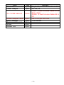
Package Content
Before you begin to install your DKVM-8E, please make
sure that you received the following materials as listed
below:
-2-
Item
DKVM-8E
Power Adapter
Qty
1 pcs.
1 pcs.
3 in 1 KVM cable kit
3 sets
Mouse Adapter cable
User’s Manual
Rack mount bracket
Screw
Rubber foot
4 pcs
1 pcs.
2 pcs.
8 pcs.
4 pcs.
Remark
Keyboard, mouse & monitor switch
DC12V,1A
1 set : 3 feet 3-in-one Cable Kit to
daisy chain
2 sets : 6 feet 3-in-one Cable Kit to
PC
DB-9 to 6-pin Mini-DIN
This manual
-3-
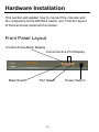
Hardware Installation
This section will explain how to connect the console and
the computers to the DKVM-4 switch unit. First the layout
of front and rear panel will be shown.
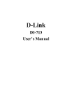
Front Panel Layout
Current Active Bank Display
Current Active Port Display
Bank Select
Port Select
-4-
Power Switch
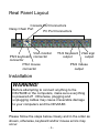
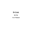
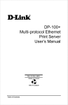
Real Panel Layout
Console Port Connectors
Daisy Chain Port
PC Port Connectors
VGA monitor
PS/2 keyboard connector
connector
PS/2 mouse
connector
PS/2 Keyboard VGA signal
output
output
PS/2 mouse
output
Installation
WARNING!
Before attempting to connect anything to the
DKVM-8E or the computers, make sure everything
is powered off . Otherwise, plugging and
unplugging cables may cause irreversible damage
to your computers and the DKVM-8E.
Please follow the steps below closely and in the order as
shown, otherwise, keyboard and/or mouse errors may
occur.
-5-
Step 1
Find a convenient place to put your DKVM-8E. Its 19” rack
mount form factor makes it ideal mountable on 19” rack.
When mounting to a rack, attach the included brackets to
the sides of the DKVM-8E. Take note of the length of your
cables so that your computers, DKVM-8E, keyboard,
mouse
and
monitor
are
distanced
properly.
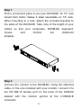
Step 2
Connect the monitor to the DKVM-8E. Using the attached
cable, or the one included with your monitor, connect it to
the HD DB-15 female port on the back of the KVM-08
labeled with the monitor symbol at the CONSOLE
connector.
-6-
Step 3
Connect the keyboard to the DKVM-8E. If you have an AT
type keyboard, you will need an AT to PS/2 adapter.
Step 4
Connect the mouse to the DKVM-8E.
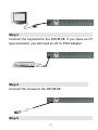
Step 5
-7-
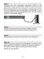
Now the PC connections will be made with the monitor
(VGA) connections first. Connect a VGA cable (15-pin
HDDB Male / Male) with the Male side to both of the PC
and the rear panel of the DKVM-8E unit to the connector
labeled VGA. Repeat this for all PCs.
Back
Back of PC
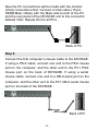
Step 6
Connect the first computer’s mouse cable to the DKVM-8E.
If using a PS/2 cable, connect one end to the PS/2 mouse
port on the computer, and the other end to the PC1 PS/2
mouse port on the back of DKVM-8E. If using a serial
mouse cable, connect one end to a DB-9 serial port on the
computer, and the other end to the PC1 DB-9 serial mouse
port on the back of the DKVM-8E.
Back of PC
-8-
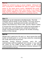
Step 7
Connect the first computer’s keyboard cable to the
DKVM-8E. Using another PS/2 cable connect one end to
PS/2 keyboard port on the computer, and the other end to
the PC1 keyboard port on the back of DKVM-8E. If your
computer has an AT type keyboard port, you will need a
PS/2 to AT keyboard adapter.
Back of PC
Step 8
Double-check all of the connections. Make sure the
keyboard and mouse cables go to the correct ports.
Step 9
Repeat step 5 to 8 for the remainder of the computers.
Step 10
Attach the power supply to the DKVM-8E unit and plug the
other end into an electrical receptacle. Now you will see
the LED for Port 1 light up, and you will hear a beep.
Switch on your monitor.
-9-
NOTE:
Please be remind to plug in power adapter. Although the
PCs connected to DKVM-8E are able to support enough
power to the stand alone switch, DKVM-8E still needs a
power adapter for daisy chain more banks. If you forgot to
plug in power adapter on the status of daisy chain, it may
cause the unpredictable behavior or shut down the PC.
Step 11
Now power up all computers simultaneously. The first
computer will be shown on the monitor. You may check to
see if the mouse, keyboard and monitor work after the
system has booted up. If this is OK, use the “Select” button
to choose the next computer and verify the functionality in
the same way. If you find errors, recheck all cables for
proper connections before going to the trouble shooting
section of this manual.
NOTE:
Please don’t switch the PC port (i.e. Don’t press the push
button of KVM switch or run hot key) while the computers
are under their boot-up process.
Normally, during boot-up process, each PC will
communicate with the keyboard and mouse. If you switch
PC ports on the KVM at this moment, it will cause
communication errors or initialization failures between PC
and keyboard or mouse.
- 10 -
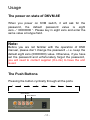
Usage
The power on state of DKVM-8E
When you power on KVM switch, it will ask for the
password, the default password value is eight
zero –“ 00000000 “. Please key in eight zero and enter the
same value at retype field.
Note:
Before you are not familiar with the operation of OSD
manual, please don’t change the password – i.e. keep the
default eight zero (00000000) value. Otherwise, if you have
set the password and unfortunately forget the password,
you will need to contact supplier (D-Link) to have the unit
re-set.
The Push Buttons
Pressing the button cyclically through all the ports.
1
2
3
4
5
Port Status
Port Select
- 11 -
6
7
8
Display LED Indication
You can press the button in order like mentioned-above
diagram. When you select one of eight PC ports and this
PC is shut down or this PC port is disconnected to the PC,
the display LED of selected port will flash. When you select
one of eight PCs ports and this PC is powered on, the
selected port LED is lit.
Reset Button
To press select and bank button of bank 1 (master)
simultaneously can reset KVM switch. This reset action will
not only return KVM switch back to initial state --- Check
the password, but also re-check all of slave banks which
connected to mast DKVM-8E.
If you add a new DKVM-8E as a slave bank, please use
reset button of master DKVM-8E to assign a new ID to it.
You can view this new slave bank go through OSD menu.
With reset command, the PC ports of DKVM-8E will not be
reset. Only power off DKVM-8E can reset PC ports.
Keyboard Hot Key Commands
You can also conve niently command DKVM-8E by
switching ports through simple key sequences. To send
commands to DKVM-8E, the “SCROLL LOCK” key must
be pressed twice within 2 seconds. You will hear a beep
for confirmation and the keyboard is in hot key mode. If
you have not pressed any key in hot key mode within 2
seconds (It means to key in any key follows up “Scroll
- 12 -
Lock” “Scroll Lock” key), the keyboard will back to under
Operation System control state.
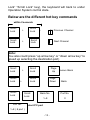
Below are the different hot key commands
within 2 seconds
Scroll
Lock
+
Scroll
Lock
+
Scroll
Lock
+
= Previous Channel
Scroll
+
Lock
= Next Channel
Note:
You also could press “up arrow key” or “down arrow key” to
speed up selecting the destination port)
Scroll
Lock
Scroll
Lock
Scroll
Lock
Scroll
Lock +
+
+
Page
Up= Previous Bank
Scroll
Lock +
+
Scroll
+
Lock
Page
= Next Bank
Down
Bank No.
1~8
Port No.
= select PC port
1~8 ( 8 port )
- 13 -
+
Port No.
+
+
0
Note:
Bank no. and port no. selection must be made using the
numeric keys on the keyboard. Numeric keys on the
keypad are not available as a hot key command.
Scroll
Lock
+
Scroll
Lock +
=BBeeper
Note:
The default Beeper function is ON
Scroll
Lock
+
Scroll
+
Lock
=
S Auto Scan
Note:
1. If you set up scan mode command already,
DKVM-8E issue one beeper for confirmation every
time when one of PC ports hop to next PC port.
2. To get out of Auto Scan Mode, press any key or
SPACE bar.
Scroll
Lock
+
Scroll
Lock +
R= OSD default value
ROM
- 14 -
REFLASH
Note:
1. Rom re-flash command need take 1~2 minutes. 2.Not
including password
Scroll
Lock
+
Scroll
Lock +
=FSearch the same PC name
FIND:¦
Note:
Search PC name starting from 1 st PC port
Scroll
Lock
+
Scroll
Lock + Space bar = On Screen Display Manual
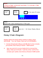
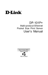
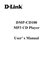
Daisy Chain Diagram
Please follow the steps below closely to daisy chain
DKVM-8E. You can daisy chain up to 8 DKVM-8Es.
1. Connect Keyboard, Mouse and Monitor to the console
port (white color block) of bank 1 KVM switch.
2.
Use one end of 3-in-one Cable Kit to connect the
daisy chain port of bank 1 and the other end for the
console port (white color block) of bank 2 KVM switch.
- 15 -
3.
Please repeat item B to daisy chain more bank as you
want. But, the maximum daisy chain bank is eight
levels.
Please use the attached 3 feet 3-in-one Cable Kit
to daisy chain the KVM Switches.
Bank:1
MASTER (Bank 1)
Bank:2
SLAVE (Bank 2)
Bank:3
SLAVE (Bank 3)
:
.
Bank:8
SLAVE (Bank 8)
Maximum 8 Levels
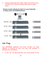
Hot Plug
The DKVM-8E supports “Hot Plug“ function for easy
addition or removal of PCs. The user can arrange or
maintain PCs as follows:
1.
A PC can be disconnected and reconnected to the
- 16 -
same or different port of the DKVM-8E without having
to power it off as long as it is not the Daisy-chain port
or pass through port.
2.
When the pass through port is active and selected,
you must switch to a different port before you change
the configuration, and then you can switch back to the
pass through port.
3.
You may unplug the mouse or the keyboard from the
console port and plug it back in at any time.
NOTE:
Some O.S. (Operation Systems) like SCO Unix are unable
to support “ Hot Plug ” function. If you apply “Hot Plug” to
this kind of O.S., it will cause unpredictable behavior or
shut down the PC. Before attempting to use “ Hot Plug ” ,
please make sure your O.S. and software driver supports
the “Hot Plug” function.
- 17 -
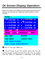
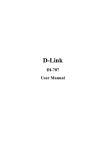
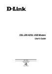
On Screen Display Operation
When you pop up the OSD manual window go through the
hot key, you will see the following small window on your
monitor.
BANK: 1 u
0 v SYSTEM 01
0 ¤ SYSTEM 03
0 ¤ SYSTEM 02
wE
0 ¤ SYSTEM 04
0 ¤ SYSTEM 05
0
SYSTEM 06
0 SYSTEM 07 0 ¤ SYSTEM 08
xOSD: 10 SEC. zCHANGE PASSWORD
ySCAN:10 SEC.{CONSOLE ON/OFF
|ESC: QUIT
ENTER:
TAB: NEXT
INSERT: EDIT
Ç/È: SELECT PORT
PgDn / PgUp: BANK SELECT
u The 1ST line bar is Bank no.
v
The 2nd block is your PC system name list. You will
find the system number list from 01 to 08. You can define
your PC name in maximum 8 characters. The factory
- 18 -
default of 8 port KVM switch PC name is from “SYSTEM
01”, “SYSTEM 02”,…, “SYSTEM 08”.
w
The sun symbol “¤ “ beside the PC name shows that
the respective PC system is powered on.
x
The “OSD: 10 SEC” means that the OSD windows
display or PC system name exists 10 sec. on your monitor.
You can modify it from 05 sec to 99 sec. The factory
default value is 10 sec.
y “SCAN TIME” is the scan interval from one PC port
hopped to the next PC port. The default SCAN time is 10
sec and the maximum scan time is 99 sec.
z “CHANGE PASSWORD” allows the user to change the
password used to access all PC systems connected. The
default password is 8 digits “ 00000000 “.
ENTER PASSWORD : ¦
ESC: QUIT
ENTER :
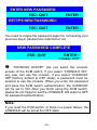
There is an enter password window showed out when you
select this item and then press the Enter. The maximum
password is eight digits. After you key in the password and
press the Enter key, there is another window for confirming
your typed password.
- 19 -
ENTER NEW PASSWORD: ¦
ESC: QUIT
ENTER :
RETYPE NEW PASSWORD: ¦ COMPLETE
ESC: QUIT
ENTER :
COMPLETE
You need to retype the password again for rechecking your
previous key-in password is matched or not.
NEW PASSWORD COMPLETE
ESC: QUIT
ENTER :
COMPLETE
{
“CONSOLE ON/OFF“ lets you select the console
access of the KVM switch. If you select “CONSOLE ON“,
any user can use the console. If you select “CONSOLE
OFF“(factory default is OFF state), a password must be
entered to use the console. When you enter the password
and pass the KVM switch authentication, the CONSOLE
will be set to ON. After you finish using the KVM switch,
please do not forget to set the CONSOLE ON state to OFF
for password authentication.
Note:
If you reset the KVM switch, or there is a power failure, the
CONSOLE will be set at the OFF state.
- 20 -
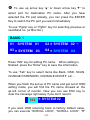
|
To use up arrow key “—“ or down arrow key “˜“ to
select port for destination PC name. After you have
selected the PC port already, you can press the ENTER
Key to switch the PC port you want immediately
To use “PgUp“ key or “PgDn” key for selecting previous or
next Bank no. (or Box No.)
BANK: 1
01
SYSTEM 01
03 ¤ SYSTEM 03
02 ¤ SYSTEM 02 E
04 ¤ SYSTEM 04
Press “INS” key for editing PC name. When editing is
finished, press the “Enter“ key to save the information.
To use “Tab“ key to select items like Bank, OSD, SCAN,
CHANGE PASSWORD, CONSOLE ON/OFF, etc…
When you finish the set up of PC name and get out of OSD
setting mode, you will find the PC name showed at the
up-left corner of monitor. Now you can use ESC key to
clear the message right away if you don’t need it.
102 ¤ SYSTEM 02
If you want OSD returning back to factory default value,
you can execute “SCROLL LOCK”, “SCROLL LOCK”, “R”
- 21 -
keys in order. The Display LEDs on the front panel will be
flashed during the refresh process.
ROM
REFLASH
When the OSD value back to default setting, the Display
LEDs on the front panel will stop flashing
- 22 -
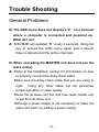
Trouble Shooting
General Problems
Q: The OSD menu does not display a “¤ “ on a channel
where a computer is connected and powered up.
What do I do?
A: ?DKVM-8E will updated “¤ “ every 2 seconds. Using hot
key to access the OSD menu again and it should
have re-detected all the active channels.
Q: When cascading the MASTER unit does not see the
slave unit(s).
A: ?Refer to the Installation section for information on how
to properly connect the daisy-chain cable.
?Make sure the daisy-chain cable that you are using is
right. Using any other cable will not guarantee
proper operation or video quality.
?Reset the all slave unit first and then reset master unit
to get the lost slave unit.
?Although a power supply is not necessary to make the
slave unit work, try adding a power supply.
- 23 -
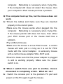
Monitor/Video Problems
Q: I am getting ghosting shadowing or fuzzy images
on my monitor. What do I do?
A: ?Check the cables and make sure they are inserted
properly.
?Your resolution and / or refresh rate is extremely high,
or your cable is too long. Replace your VGA cables
with coaxial, double-shielded cables.
?Check to make sure that the power adapter is plugged
in and is working properly. Make sure the power
switch is on.
?Lower your refresh rate and / or screen resolution
settings.
Keyboard Problems
Q: The keyboard is not detected, or a keyboard error is
reported during boot-up.
A: ?Check the cables and make sure they are inserted
properly in the correct channels.
?Check to make sure that the power adapter is plugged
in and is working properly. Make sure the power switch
is on.
?Do not press any keys on the keyboard while the
selected computer is booting up. This is true for any
- 24 -
PC, whether stand-alone or connected to a DKVM-8E.
Q: The computers boot up fine, but the keyboard does
not work.
A: ?Check the cables and make sure they are inserted
properly in the correct ports.
?Make sure the keyboard works when directly plugged
into the computers.
?Try a different keyboard, but use only 101,102 or
104-key keyboards.
?Make sure that the keyboard driver is for 101, 102 or
104-key keyboards, and not old XT keyboards.
?Check to make sure that the power adapter is plugged
in and is working properly. Make sure the power
switch is on.
PS/2 Mouse Problems
Q: The mouse is not detected during boot-up.
A: ?Check the cables and make sure they are inserted
properly in the correct ports.
?Check your computer / motherboard documentation
making sure that the PS/2 mouse port (or IRQ) is
enabled.
?Make sure the mouse is directly plugged into the
- 25 -
computer. Rebooting is necessary when trying this.
If the computer still does not detect the mouse, then
your computer’s PS/2 mouse port has a problem.
Q: The computer boot up fine, but the mouse does not
work.
A: ?Check the cables and make sure they are inserted
properly in the correct ports.
?Make sure the mouse works when plugged into the
computer. Rebooting is necessary when trying this.
If the mouse pointer still does not move, then either
your PS/2 mouse port or the mouse itself has a
problem.
?Try a different mouse.
?Make sure the mouse is a true PS/2 mouse. A combo
mouse will work just a s long as it is set for PS/2
mode with the correct adapter. A serial-only mouse
with a combo mouse adapter WILL NOT work.
?Check to make sure that the power adapter is plugged
in and is working properly. Make sure the power
switch is on.
Q: When I switch from one port to another, mouse
movement is completely erratic. What do I do?
A : Switch the console port to the problem PC port and
power on this PC again to get the mouse.
- 26 -
Problems with computers using serial
mouse output
Note:
The DKVM-8E has integrated mouse conversion
technology. This technology converts the PS/2 mouse
signals at the console to serial mouse signals.
Q: The computers boot up fine, but the serial mouse
port of PC does not work
A: ?Check the adapter and make sure they are inserted
properly in the correct ports.
?Make sure the adapter pin out is right.
Q: The wheel on the Mouse does not work on my
computer. Why?
A: ?Make sure the mouse is fully compatible to Microsoft®
Intellimouse® or Microsoft® Intellimouse® Explorer®.
?DKVM-8E does not support special wheel function of
mouse.
Problems with power supply
- 27 -
Q: The power switch is off, but the switch still works
fine or power adapter
Is unplugged from the switch, but the switch still
works fine ?
A: DKVM-8E draws the power source from power adapter
and PC’s PS2 port. Some PC’s PS2 port can support
enough power for the switch, but some PC’s PS2 port ( like
laptop, notebook computer…etc.) is unable to supply
enough power for the switch. In order to make sure the
system can work steadily, please do not set power switch
to off state or remove the power adapter from the switch.
Although the PCs connected to DKVM-8E are able to
support enough power to the stand alone switch,
DKVM-8E still needs a power adapter for daisy chain more
banks.
- 28 -
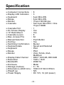
Specification
Computer Connections
Display LED Indication
q Keyboard
q Mouse
q Monitor
q Cascade
:
:
:
:
:
:
Cascade Port
On Screen Display
q 19” Rack Mount
q Cascade (Level)
q Max. Access PCs
q Manual Selection
q Hot Key
q Switching Confirmation
q Keyboard state
q Keyboard
q Mouse
q Monitor
:
:
:
:
:
:
:
:
:
:
:
:
Display Data Channel
Resolution
q Bandwidth
q Enclosure
q Storage (Celsius)
q Dimension (LxWxH mm)
q Weight (g)
q Power Supply
:
:
:
:
:
:
:
:
q
q
q
q
q
q
8
3
6-pin Mini-DIN
6-pin Mini-DIN
15-pin HD DB type
Two 6-pin Mini-DIN + One
15-pin HDDB
1
Yes
Yes
8
64
Push Button
Yes
Buzzer
Saved and Restored
PS/2
PS/2
VGA, SVGA, XGA,
MultiSync
DDC1, DDC2B, DDC2AB
1920 x 1440
200M Hz
Metal
0 ~ 70
169mm*410mm*45mm
N/A
DC 12V, 1A (AC power)
- 29 -
FCC Certifications
This equipment has been tested and found to comply with
the limits for a Class B digital device, pursuant to Part 15 of
the FCC Rules. These limits are designed to provide
reasonable protection against harmful interference in a
residential installation. This equipment generates, uses
and can radiate radio frequency energy and, if not installed
and used in accordance with the instructions, may cause
harmful interference to radio communications. However,
there is no guarantee that interference will not occur in a
particular installation. If this equipment does cause
harmful interference to radio or television reception, which
can be determined by turning the equipment off and on,
the user is encouraged to try to correct the interference by
one or more of the following measures:
§ Reorient or relocate the receiving antenna.
§ Increase the separation between the equipment and
receiver.
§ Connect the equipment into an outlet on a circuit
different from that to which the receiver is
connected.
§ Consult the dealer or an experienced radio/TV
technician for help.
Shielded interface cables must be used in order to comply
with emission limits.
You are cautioned that changes or modifications not
expressly approved by the party responsible for
compliance could void your authority to operate the
equipment.
This device complies with Part 15 of the FCC rules.
Operation is subject to the following two conditions:
(1) This device may not cause harmful interference, and (2)
This device must accept any interference received,
including interference that may cause undesired operation.
CE Mark Warning
This is a Class B product. In a domestic environment, this
product may cause radio
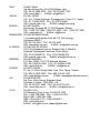
D-Link Offices
AUSTRALIA
D-LINK AUSTRALIA
Unit 16, 390 Eastern Valley Way, Roseville, NSW 2069, Australia
TEL: 61-2-9417-7100 FAX: 61-2-9417-1077
TOLL FREE: 1800-177-100 (Australia), 0800-900900 (New Zealand)
URL: www.dlink.com.au
E- MAIL: [email protected], [email protected]
CANADA
D-LINK CA NADA
2180 Winston Park Drive, Oakville, Ontario, L6H 5W1 Canada
TEL: 1-905-829-5033 FAX: 1-905-829-5223
TOLL FREE: 1-800-354-6522
URL: www.dlink.ca
E- MAIL: [email protected]
CHILE
D-LINK SOUTH AMERICA
Isidora Goyeechea 2934 of 702, Las Condes, Santiago Chile S.A.
TEL: 56-2-232-3185 FAX: 56-2-232-0923
URL: www.dlink.cl
E- MAIL: [email protected], [email protected]
CHINA
D-LINK CHINA
2F. Sigma Building, 49 Zhichun Road, Haidian District,
100080 Beijing, China
TEL: 86-10-88097777 FAX: 86-10-88096789
URL: www.dlink.com.cn
DENMARK
D-LINK DENMARK
Naverland 2, DK-2600 Glostrup, Copenhagen, Denmark
TEL:45-43-969040 FAX:45-43-424347
URL: www.dlink.dk
E- MAIL: [email protected]
EGYPT
D-LINK MIDDLE EAST
7 Assem Ebn Sabet Street, Heliopolis Cairo, Egypt
TEL: 202-2456176 FAX: 202-2456192
URL: www.dlink-me.com E-MAIL: [email protected]
FRANCE
D-LINK FRANCE
Le Florilege #2, Allee de la Fresnerie
78330 Fontenay le Fleury France
TEL: 33-1-302-38688 FAX: 33-1-3023-8689
URL: www.dlink-france.fr E-MAIL: [email protected]
GERMANY
D-LINK Central Europe/D-Link Deutschland GmbH
Schwalbacher Strasse 74
D-65760 Eschborn, Germany
TEL: 49-6196-77990 FAX: 49-6196-7799300
URL: www.dlink.de
E-MAIL: [email protected]
BBS: 49-(0)6192-971199 (Analog) 49-(0)6192-971198 (ISDN)
INFO LINE: 00800-7250-0000 (toll free)
HELP LINE: 00800-7250-4000 (toll free)
REPAIR LINE: 00800-7250-8000
INDIA
D-LINK INDIA
Plot No.5, Kurla-Bandra Complex Road,
Off Cst Road, Santacruz (E), Bombay - 400 098 India
TEL: 91-22-652-6696 FAX: 91-22-652-8914
URL: www.dlink-india.com
E-MAIL: [email protected]
ITALY
D-LINK ITALIA
Via Nino Bonnet No. 6/b, 20154 Milano, Italy
TEL: 39-02-2900-0676 FAX: 39-02-2900-1723
URL: www.dlink.it
E-MAIL: [email protected]
JAPAN
D-LINK JAPAN
10F, 8-8-15 Nishi-Gotanda, Shinagawa-ku, Tokyo 141, Japan
TEL: 81-3-5434-9678 FAX: 81-3-5434-9868
URL: www.d-link.co.jp
E-MAIL: [email protected]
RUSSIA
D-LINK RUSSIA
Michurinski Prospekt 49, 117607 Moscow, Russia
TEL: 7-095-737-3389, 7-095-737-3492 FAX: 7-095-737-3390
URL: www.dlink.ru
E-MAIL: [email protected]
SINGAPORE D-LINK INTERNATIONAL
1 International Business Park, #03-12 The Synergy,
Singapore 609917
TEL: 65-774-6233 FAX: 65-774-6322
URL: www.dlink-intl.com
E-MAIL: [email protected]
S. AFRICA
D-LINK SOUTH AFRICA
102-106 Witchhazel Avenue, Einetein Park 2, Block B,
Highveld Technopark Centurion, South Africa
TEL: 27(0)126652165 FAX: 27(0)126652186
URL: www.d-link.co.za
E-MAIL: [email protected]
SWEDEN
D-LINK SWEDEN
P.O. Box 15036, S-167 15 Bromma Sweden
TEL: 46-(0)8564-61900 FAX: 46-(0)8564-61901
URL: www.dlink.se
E-MAIL: [email protected]
TAIWAN
D-LINK TAIWAN
2F, No. 119 Pao-Chung Road, Hsin-Tien, Taipei, Taiwan,
TEL: 886-2-2910-2626 FAX: 886-2-2910-1515
URL: www.dlinktw.com.tw
E-MAIL: [email protected]
U.K.
D-LINK EUROPE
4th Floor, Merit House, Edgware Road,
Colindale, London, NW9 5AB, U.K.
TEL: 44-20-8731-5555 FAX: 44-20-8731-5511
URL: www.dlink.co.uk
E-MAIL: [email protected]
U.S.A.
D-LINK U.S.A.
53 Discovery Drive, Irvine, CA 92618 USA
TEL: 1-949-788-0805 FAX: 1-949-753-7033
INFO LINE: 1-800-326-1688
BBS: 1-949-455-1779, 1-949-455-9616
URL: www.dlink.com
E- MAIL: [email protected], [email protected]
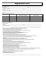
Registration Card
Print, type or use block letters.
Your name: Mr./Ms _____________________________________________________________________________
Organization: ________________________________________________ Dept. ____________________________
Your title at organization: ________________________________________________________________________
Telephone: _______________________________________ Fax:________________________________________
Organization's full address: ______________________________________________________________________
____________________________________________________________________________________________
Country: _____________________________________________________________________________________
Date of purchase (Month/Day/Year): _______________________________________________________________
Product Model
Product Serial No.
* Product installed in type of
computer (e.g., Compaq 486)
* Product installed in
computer serial No.
(* Applies to adapters only)
Product was purchased from:
Reseller's name: ______________________________________________________________________________
Telephone: _______________________________________ Fax:________________________________________
Reseller's full address: _________________________________________________________________________
_________________________________________________________________________
_________________________________________________________________________
Answers to the following questions help us to support your product:
1. Where and how will the product primarily be used?
oHome oOffice oTravel oCompany Business oHome Business o Personal Use
2. How many employees work at installation site?
o1 employee o2-9 o10-49 o50-99 o 100-499 o 500- 999 o1000 or more
3. What network protocol(s) does your organization use ?
oXNS/IPX oTCP/IP oDECnet oOthers_____________________________
4. What network operating system(s) does your organization use ?
oD-Link LANsmart oNovell NetWare oNetWare Lite oSCO Unix/Xenix oPC NFS o3Com 3+Open
oBanyan Vines oDECnet Pathwork oWindows NT oWindows NTAS oWindows '95
oOthers__________________________________________
5. What network management program does your organization use ?
oD-View oHP OpenView/Windows oHP OpenView/Unix o SunNet Manager oNovell NMS
oNetView 6000 o Others________________________________________
6. What network medium/media does your organization use ?
oFiber-optics oThick coax Ethernet oThin coax Ethernet o10BASE-T UTP/STP
o100BASE-TX o 100BASE-T4 o 100VGAnyLAN oOthers_________________
7. What applications are used on your network?
oDesktop publishing oSpreadsheet oWord processing oCAD/CAM
oDatabase manag ement oAccounting oOthers_____________________
8. What category best describes your company?
oAerospace oEngineering oEducation oFinance oHospital oLegal oInsurance/Real Estate oManufacturing
oRetail/Chainstore/Wholesale o Government oTransportation/Utilities/Communication oVAR
oSystem house/company oOther________________________________
9. Would you recommend your D-Link product to a friend?
oYes oNo oDon't know yet
10.Your comments on this product?
__________________________________________________________________________________________
__________________________________________________________________________________________