1
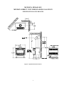
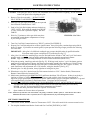
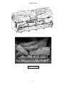
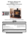
MENDOTA MEDALLION DIRECT VENT FREESTANDING GAS STOVE WITH HEARTHGLO SEALED COMBUSTION SYSTEM Model SDV40 NATURAL GAS OR LP GAS INSTALLATION & OPERATING INSTRUCTIONS NO. 0806 WARNING: This product must be installed by a licensed plumber or gas fitter when installed in the commonwealth of Massachusetts. Improper installation, adjustment, alteration, service or maintenance can cause injury or property damage. Refer to this manual. For assistance or additional information consult a qualified installer, service agency or the gas supplier. FOR YOUR SAFETY: DO NOT STORE OR USE GASOLINE OR OTHER FLAMMABLE VAPORS & LIQUIDS IN THE VICINITY OF THIS OR ANY OTHER APPLIANCE. IF YOU SMELL GAS: WARNING: 1. 2. 3. 4. 5. 6. 7. OPEN WINDOWS. DON'T TOUCH ELECTRICAL SWITCHES. DO NOT USE ANY PHONE IN YOUR BUILDING EXTINGUISH ANY OPEN FLAME IMMEDIATELY CALL YOUR GAS SUPPLIER FROM A NEIGHBOR'S PHONE. FOLLOW THE GAS SUPPLIERS INSTRUCTIONS. IF GAS SUPPLIER IS UNAVAILABLE, CALL YOUR FIRE DEPARTMENT. MENDOTA GAS FIREPLACE INSERTS ARE HEAT PRODUCING APPLIANCES. DO NOT BURN WOOD, PAPER OR OTHER MATERIALS IN THE INSERT. THE FIREPLACE INSERT IS DESIGNED AS A SUPPLEMENTAL HEAT SOURCE. IT SHOULD NOT BE USED AS A WHOLE HOUSE HEATING SYSTEM. WARNING: IF THE INFORMATION IN THIS MANUAL IS NOT FOLLOWED EXACTLY, A FIRE OR EXPLOSION MANY RESULT CAUSING PROPERTY DAMAGE, PERSONAL INJURY, OR LOSS OF LIFE. INSTALLATION AND SERVICE MUST BE PERFORMED BY A QUALIFIED INSTALLER, SERVICE AGENCY, OR THE GAS SUPPLIER. IMPORTANT: THESE INSTRUCTIONS ARE TO REMAIN WITH THE HOMEOWNER! TABLE OF CONTENTS GAS LABEL REPRESENTATION ............................................................................................................3 LOCATING THE STOVE...........................................................................................................................4 ELECTRICAL REQUIREMENTS .............................................................................................................4 SPECIFICATIONS & CLEARANCES.......................................................................................................5 INSTALLATION INSTRUCTIONS - BLOWER OPERATION - POWER FAILURE OPERATION ....6 FLUE VENTINGINSTRUCTIONS ............................................................................................................8 VENTING COMPONENT INSTALLATION SEQUENCE AND PARTS LIST.....................................9 MINIMUM RISE THROUGH THE WALL VENTING ............................................................................11 ELEVATED THROUGH THE WALL VENTING ....................................................................................12 VERTICAL THROUGH THE ROOF VENTING ......................................................................................12 GAS SUPPLY REQUIREMENTS ..............................................................................................................15 GAS PRESSURE REQUIREMENTS .........................................................................................................17 INSTALLATION & LIGHTING CHECK OFF LIST ................................................................................18 LIGHTING INSTRUCTIONS.....................................................................................................................19 LOG INSTALLATION ...............................................................................................................................21 THERMOSTAT INFORMATION ..............................................................................................................21 TROUBLE SHOOTING..............................................................................................................................23 CUSTOMER INFORMATION AND TROUBLE-SHOOTING ................................................................24 MAINTENANCE ........................................................................................................................................26 NATURAL TO LP CONVERSION ............................................................................................................26 REPLACEMENT PARTS ...........................................................................................................................28 WARRANTY REGISTRATION.................................................................................................................34 SPECIFICATIONS MODEL SDV40 MEDALLION High Fire - Adjustable to - Low Fire BTUH +INPUT NAT. GAS L.P. GAS 40,000 35,000 27,800 26,100 NOTE: AN LP CONVERSION KIT #HA-32-00040 MUST BE PURCHASED SEPARATELY – SEE PAGE 27. STEADY STATE A.F.U.E. Nat. 81.77% 70.7% 78.3% L.P. 78.8% 72.2% 79.5% OVERALL EFFICIENCIES ......................... CANADA STEADY STATE FLUE VENT LINER .................................... 4" INNER; 6 5/8" OUTER, COAXIAL TOTAL WEIGHT ......................................... 225 LB. SAFETY........................................................ AGA CERTIFIED PILOT GENERATOR, MILLIVOLT THERMOCOUPLE SYSTEM ACTIVATED WITH SWITCH OR THERMOSTAT. GAS REQUIREMENTS...SUPPLY PRESSURE: NAT. GAS: L.P. GAS: GAS INLET: MAIN ORIFICE: 7" W.C. [5" W.C. MIN., 11" W.C. MAX.] 11" W.C. [11" W.C. MIN., 13" W.C. MAX.] 3/8" N.P.T. #30 NAT, #50 L.P. Certified under ANSI Z21.11.1-1993 "Vented Room Heaters"; CAN 2.1-M89 "Vented Room Heaters, CAN/CGA 1.17 M91 "Gas-fired appliances for use at high altitudes"; ANSI Z21.50-1996, CGA 2.22 - M96 "Vented Gas Fireplaces" and UL 307B-1987 "Gas Burning Heating Appliances for Mobile Homes", not for use with solid fuel. Approved for bedroom installations. Gas appliances must be tested and certified by a nationally recognized testing and certification agency to American National Standards Institute - ANSI Gas Appliance Safety Standards. The Mendota Freestanding Gas Stove has been tested and certified by Intertek Testing Services 8431 Murphy Drive, Middleton, WI 53562. STOVE IS SHIPPED COMPLETELY ASSEMBLED AND PAINTED BLACK METALLIC. INCLUDES BLOWER W/RHEOSTAT, BURNER, HEARTHGLO SEALED COMBUSTION SYSTEM. GOLD PLATED GRILL RODS AND DOOR, 4 CERAMIC FIBER LOGS & COALS, NEO-CERAM GLASS, PIEZO PILOT AND AGA CERTIFIED SAFETY SYSTEM. OPTIONS: THERMOSTAT, GOLD PLATED TRIVET PLATE AND REMOTE CONTROL. CONGRATULATIONS! 1 You are the owner of a world class heat producing gas direct vent sealed combustion stove. This elegant, highly efficient Stove will be a constant source of comfort and fascination. It will be the focal point of beauty and interest in your home. The Mendota Gas Stove is a true heating appliance incorporating the traditional aesthetics of stove fire viewing with the controllability and fuel efficiency of a home gas furnace. Of particular interest is the low fuel consumption and brilliant fire viewing afforded by the patented realistic HearthGlo wood fire-like combustion system. Carefully read the following instructions prior to actual installation. Proper Mendota Gas Stove installation and operation will give you years of safe trouble free comfort and enjoyment. If you have any questions regarding installation or operation of your Mendota Stove please contact your local dealer. ......CAUTION..... FOR YOUR SAFETY do not install or operate your Mendota Gas Freestanding Stove without first reading and understanding this manual. Any installation or operational deviation from this manual voids the Mendota Gas Stove Warranty and may prove hazardous! Due to high temperatures, the Stove should be located out of traffic and away from furniture and draperies. Children and adults should be alerted to the hazards of high surface temperature and should stay away to avoid burns or clothing ignition. Young children should be carefully supervised when they are in the same room as the Mendota Gas Stove. Clothing or other flammable material should not be placed on or near the Stove. The Mendota Gas Stove is a powerful, efficient heating unit. It has been designed as a major source of supplemental heat. As with any mechanical appliance there can be component shut downs. It is advisable to have an alternate (back-up) heat supply. Installation, repair and any adjustments to logs or burner must be done by a qualified service person. The Stove should be inspected before use and at least annually by a professional service person. More frequent cleaning may be required due to excessive lint from carpeting, bedding material, carbon build-up, etc. It is imperative that control compartments, burners and circulating air passageways of the appliance be kept clean. The burner and pilot flames and logs should be visually checked periodically. DO NOT use this Stove if any part has been under water or exposed to moisture corrosion. Immediately call a qualified service technician to inspect the Stove and replace any part of the control system and any gas control which has been under water. DO NOT use this Stove if the burner does not light immediately. Turn unit off and call Mendota approved service person if there is any delay in burner light-off. It is Johnson Gas Appliance Company's policy that no responsibility is assumed by the Company or by any of its employees or representatives for any damages caused by an inoperable, inadequate, or unsafe condition which is the result, either directly or indirectly, of any improper operation, installation or servicing procedures. Building Permit and Installation Inspection Approval Requirements All installations of Mendota Fireplace and Inserts must comply with all the requirements stated in this Installation and Operating Instructions Manual. The Dealer and/or installer must also obtain all required Building Permits and Inspection Approval from the local building inspection department or the local body having jurisdiction. In order to validate warranty coverage, Mendota may require facsimile copies of the Building Permit and Inspection Approval forms. Failure to provide adequate proof that the installation conforms to all local requirements and the requirements stated in the Installation and Operating Instructions Manual will void all applicable warranty. INSTALLER: THESE INSTRUCTIONS ARE TO REMAIN WITH HOMEOWNER. 2 "LABEL REPRESENTATION" WARNOCK HERSEY GAS LOGO LISTED GAS-FIRED DIRECT VENT ROOM HEATER POÊLE AU GAZ HOMOLOGUE’, A AÉRATION DIRECTE MODEL: SDV40 MEDALLION CERTIFIED FOR CANADA HOMOLOGUÉ POUR LE CANADA Also for use in mobile (manufactured) homes after first sale of home. Convenant également pour installations dans des maisons mobiles. Tested to (Testé aux normes) ANSI Z21.11.1-1993, CAN1-2.1-M89, CAN/CGA 2.17-M91, ANSI Z21.50-1996 and CAN/CGA 2.17--M91,ANSI Z21.50-1996-CSA 2.22-M96, UL 307B-1996. _________________________________________________ WARNING: Improper installation, adjustment, alteration, service or maintenance can cause property damage, personal injury, or loss of life. Refer to the owner's information manual provided with this appliance. Installation and service must be performed by a qualified installer, service agency or the gas supplier. Use only glass assemblies certified for use with this appliance. Do not operate with glass panel(s) removed, cracked, or broken. MISE EN GARDE: Installation, réglage, modification, entretien ou depannage non appropriés pourront causer des blessures ou des dommages materiels. Réferéz-vous au manuel du proprietaire fourni avac cet appariel. Pour assistance ou renseignements complémentaires, veuillez consulter un installateur expérimenté, une agence dé depannage/entreitien ou cotre compagnie gaziére. Pour utilisation avec les portes en verre certifiée l'appareil suelement. Ne pas opérer avec le verriére enlever, craquelure, brise. NOT FOR USE WITH SOLID FUEL (NE DOIT PASÉ UTILISÉ AVEC UN COMBUSIBLE SOLIDE) NATURAL GAS (Gaz Naturel) PROPANE GAS (Gaz de petrole liquefie (GPL)) Input Rating (Btu/hr) 0-1370 m (Entrée nominale) 40,000 35,000 Min. Input Rating (Btu/hr) 0-1370 m (Mininale Entrée nominale) 27,800 26,100 Orifice (DMS) )-1370 m (Orifice) 30 50 Maximum output (Btu/hr) (Sortie maximale) 31,300 27,800 Manifold Pressure (in w.c./kPa) (Pression au collecteur) 3.5/0.87 10.0/2.5 Manifold Pressure, low (in w.c./kPa) Pression d'entree minimale) 1.7/0.42 3.6/0.90 Minimum Inlet Pressure (in w.c./kPa) (Pression d'entrée minimale) 5.0/1.25 11.0/2.75 _______________________________________________ This appliance must be installed in accordance with local codes if any; If not, follow ANSI Z223.1 or CAN/CGA-B149. Mobile (Mfd.) home installations must adhere to Title 24 CFR, Part 3280, or CSA Z240.4. Cet appareil sera installé conformémént avec les codes locaux, le cas écheant. Si aucun code n'existe, suivez la norme ANSI Z223.1 ou la norme CAN/CGA (ACNOR)-B149. _______________________________________________ MINIMUM CLEARANCES FROM COMBUSTIBLE CONSTRUCTION Unit to sidewall 10 in. (255 mm) Unit top to ceiling 39 in. (990 mm.) Unit to backwall 2 in. (50 mm.) Outlet vent to enclosure top 4 in. (105 mm.) CAUTION: Hot whil in operation. Do not touch. Keep children, clothing, furniture, and flammable liquids or vapors away. ATTENTION: L'appareil est chaud lorsqu'il fonctionne. Ne pas toucher l'appareil. Survieller les enfants. Garder les vétements, les meubles, l'essence ou autres liquides a capeur inflammables loin de l'appareil. _______________________________________________ Electrical Rating (Courant nominal): 120 volts 60 Hz Less than 1 Ampere _______________________________________________ Manufactured by (Fabriqué par): JOHNSON GAS APPLIANCE CEDAR RAPIDS, IOWA DO NOT REMOVE OR COVER THIS LABEL VEILLEZ Á NE JAMAIS ENLEVER NI DISSIMULER CETTE ÉTIQUETTE WH# __________________ TEST STANDARD CERTIFICATION Gas appliances must be tested and certified by a nationally recognized testing and certification laboratory to ANSI (American National Standards Institute) gas appliance safety standards. The Mendota Gas Stove has been tested and certified by Intertek Testing Services, 8431 Murphy Drive, Middleton, Wisconsin 53562 to ANSI1 Z21.11.1-1993 "Vented Room Heaters"; CAN 2.1-M89 "Vented Room Heaters"; CAN/CGA 1.17-M91 "Gas-Fired Appliances for use at high altitudes"; ANSI Z21.50-1996, CGA 2.22-M96 "Vented Gas Fireplaces; and UL307B-1987 "Gas Burning Heating Appliances for mobile homes, not for use with solid fuel. The Mendota Gas Stove has met all necessary AGA/ANSI Standards and is fully certified for installation in any community. MAIN GAS CONTROL INSTALLATION 1. 2. 3. 4. 5. 6. DO NOT USE THIS STOVE IF ANY PART HAS BEEN UNDER WATER OR EXPOSED TO MOISTURE CORROSION. IMMEDIATELY CALL A QUALIFIED SERVICE TECHNICIAN TO INSPECT THE STOVE AND REPLACE ANY PART OF THE CONTROL SYSTEM AND ANY GAS CONTROL WHICH HAS BEEN UNDER WATER. DO NOT insert any object other than suitable pipe or tubing in the inlet or outlet of the main gas control. Internal damage may occur and result in a hazardous condition. DO NOT connect the Stove before pressure testing gas piping and checking for gas leaks. Damage may result causing gas leakage. DO NOT grip gas control body with a pipe wrench or vise. Damage may result causing gas leakage. Use inlet or outlet bosses, or special body wrench. DO NOT use "off/on/pilot" gas knob to adjust gas flow. Leak test with a soap solution with main burner "ON". 3 LOCATING THE STOVE SAFETY AND STRUCTURAL CONCERNS: The Mendota Direct Vent Freestanding Stove must be installed and serviced by a qualified Mendota approved service person. The Mendota Direct Vent Freestanding Stove may be placed within 2" of a rear wall, within 10" of side walls, within 1 1/2" of corner walls and 39" below an alcove ceiling [See Figure 2: Specifications & Clearances on page 5]. The Stove can be installed on any rigid floor construction. A metal or wood floor protector extending the full width and depth of the Stove MUST be used when the Stove is installed on carpet, vinyl or any combustible surface other than wood flooring. The stove is equipped with a safety control system designed to protect against improper venting of combustion products. VENTING REQUIREMENTS: Use only approved direct venting kits when installing your stove. Closely follow venting directions and requirements (see FLUE VENTING INSTRUCTIONS starting on page 8). Observe the restriction relating to vent position on exterior of home (see Exterior Vent Locations on page 7). HEATING PERFORMANCE: The Mendota Direct Vent Freestanding Stove is a true, high efficiency gas heater. With its heat input of 40,000 (35,000 L.P.) BTUH the Mendota Stove will heat a large area of your home if situated to maximize heat circulation. NOTE: The Stove is a major source of supplemental heat. Air movement options for maximizing heat circulation which can be considered are through-the-wall grills or floor grills, or the continuous operation of central heating blowers or ceiling fans. The most efficient and successful method for overall heat distribution is a ceiling fan - we recommend this method for the owner who wishes to maximize hot air distribution and efficient utilization of heat. The heat input of the Stove can be reduced by slowly turning the Hi/Lo temperature knob on the front of the gas valve counterclockwise from "Hi" to "Lo". The blower can also be turned down or off. Figure 1: Main Gas Valve ELECTRICAL REQUIREMENTS: The blower requires a 115 volt electrical service supplied at the Stove location at the time of installation. The blower must be electrically grounded in accordance with local codes or in the absence of local codes, with the National Electric Code ANSI/NFPA 70-1987 (CSA C22.1-Canadian Electrical Code) or most current edition. The blower is equipped with a three-prong (grounding) plug for your protection against shock hazard and should be plugged directly into a properly grounded three-prong receptacle. DO NOT CUT OR REMOVE THE GROUNDING PRONG FROM THIS PLUG! If an optional thermostat is being used, thermostat wire should be run from desired thermostat location (or "on/off" switch) to the terminals located on back of pedestal--See optional thermostat installation section [See page 22]. An inlet hole is provided on the rear of the pedestal for gas connection. 4 MENDOTA MEDALLION MENDOTA DIRECT VENT FREESTANDING GAS STOVE SPECIFICATIONS & CLEARANCES Figure 2: Specifications & Clearances 5 INSTALLATION INSTRUCTIONS The Mendota Stoves must be installed in accordance with local codes, if any, if not, follow the current edition of ANSI.Z223.1 (US Installation) or CAN1-B149 (Canadian Installations). For mobile home installation, install per the manufactured home construction and safety standard, title 24 CFR, part #3280 (U.S.) or CAN/CSA Z240 MH (Canada). The SDV Stove must be installed by a qualified Mendota approved service person. 1. Carefully unpack the Stove. Inspect packaging for loose parts. You should find a trivet plate. 2. Position Stove in its final desired location [See Page 4]. Be sure to maintain minimum clearances to combustibles. Check to be sure all venting restrictions and requirements are being followed (See Pg. 716). Circulating room air enters the fan through the back of the pedestal. Carefully check to be certain that nothing blocks air entry to this area. Lower front door must also be free to open easily for inspection and servicing of the burner system. CAUTION: When the Stove is installed directly on carpeting, vinyl or other combustible material other than wood flooring, the Stove MUST be installed on a metal or wood protection panel extending the full width and depth of the Stove. 3. Remove front glass window/door by releasing the 4 turn latches behind side doors (rotate latches counterclock-wise and pull outward) and carefully sliding glass door forward. 4. You are now ready to hook up the gas supply. Be sure gas plumbing instructions [page 16 & 17] and all state and local codes are carefully followed. 5. Use approved flexible gas connection or rigid piping [depending on state & local codes] to attach burner to gas supply. Be sure correct size IPT black iron gas supply line is used [See Table 1: Gas Supply Line Sizing on page 16]. CAREFULLY CHECK FOR GAS LEAKS. 6. Connect gas supply line to 3/8" inlet nipple on the rear of the stove pedestal. (See FIGURE 6: Piping Detail, page 16.) 7. To use the blower there must be a 115 Volt electricity source within 5' of Stove. (See Pg. 4 & Pg. 26) IMPORTANT: Any safety screen, guard, glass, grill, pressure relief cap, etc. removed for servicing a fireplace/room heater must be replaced prior to operating the fireplace/room heater. BLOWER OPERATION The Mendota SDV40 Stove is designed so the blower operates automatically when main burner is on and rheostat is “on”. The blower output can be regulated with the rheostat (included). NOTE: There will be a time delay in blower operation during "heat-up" (approx. 1/2 hour) and extended blower operation during "cool-down" of unit. (approx. 1/2 hour) OPERATION DURING POWER OUTAGES The stove is designed to operate during power outages. EXTERIOR VENT LOCATIONS AND RESTRICTIONS 6 Figure 3: Exterior Vent Locations ∨ - Vent Terminal ∧ - Air Supply Inlet ≡ - Area where terminal is not permitted A= Clearance above grade, veranda, porch, deck, or balcony (*12 inches (30 cm) minimum) H= *Not to be installed above a meter/regulator assembly within 3 feet (90 cm) horizontally from the center-line of the regulator B= Clearance to window or door that may be opened (*12 inches (30 cm) minimum) I= Clearance to service regulator vent outlet (*6 feet (1.8m) minimum) Clearance to non-mechanical air supply inlet to building or the combustion air inlet to any other appliance. (*12 inches (30 cm) minimum) C= Clearance to permanently closed window (minimum 12 inches (30 cm) recommended to prevent condensation on window) D= Vertical clearance to ventilated soffit located above the terminal from the center-line of the terminal (18 inches (46 cm) minimum) K= Clearance to a mechanical air supply inlet (*6 feet (1.8 m) minimum) E= Clearance to unventilated soffit (12 inches (30 cm) minimum) L= † Clearance above paved side-walk or a paved driveway located on public property (*7 feet (2.1 m) minimum) F= Clearance to outside corner - 6 inches (15 cm) M= Clearance under veranda, porch, deck, or balcony (*12 inches (30 cm) minimum ‡) G= Clearance to inside corner - 12 inches (30 cm) J= † A vent shall not terminate directly above a side-walk or paved driveway which is located between two single family dwellings and serves both dwellings. ‡ Only permitted if veranda, porch, deck, or balcony, is fully open on a minimum of 2 sides beneath the floor. * As specified in CGA B1:19 Installation Codes (1991). Note: Local codes or regulations may require different clearances. 7 FLUE VENTING INSTRUCTIONS The Mendota Stove must be vented using the Mendota/Dura-Vent venting system. All warranties will be voided and serious fire, health or other safety hazards may result from any of the following actions: Instal-lation of any damaged component; unauthorized modification of vent system; installation of stove and vent system by unauthorized personnel; and vent system installation of any components not manufactured or approved by Simpson Dura-Vent or Mendota; failure to meet all clearance requirements; failure to properly twist-lock all components. Consult local building codes before beginning the installation. WARNING Always maintain required clearances (air spaces) to combustibles to prevent a fire hazard. Do not fill air spaces with insulation. Check installation instructions for minimum clearance requirements between the outer walls of the vent pipe and nearby combustible surfaces. Be sure to check the vent termination clear-ance requirements from decks, windows, soffitts, gas regulators, air supply inlets, and public walkways, as specified in these installation instructions and local building codes (See page 7). The gas appliance and vent system must be vented directly to the outside of the building, and never attached to a chimney serving separate solid fuel or gas burner appliance. Each direct vent gas appliance must have its own separate vent system. Common vent systems are prohibited. Do not recess vent termination into a wall or siding. WE STRONGLY RECOMMEND THAT FIXED LENGTH PIPE SECTIONS BE USED IN PLACE OF TELESCOPING SECTIONS WHENEVER POSSIBLE Note: When using Dura-vent DV pipe you must use a silicate stove masonry sealant [Millpak Sealant #65-06-00909] on all inner pipe joints. On the exterior (air intake) pipe joints, high temperature foil tape may be used instead of the masonry sealant. Contact your dealer to obtain this sealant material. DO NOT SEPARATE TELESCOPING SECTIONS. THEY MUST BE USED AS COMPLETE ASSEMBLIES. SAFETY PRECAUTIONS FOR THE INSTALLER 1. Wear gloves and safety glasses for protection. 2. Exercise extreme caution when using ladders or on rooftops. 3. Be aware of electrical wiring locations in walls and ceilings. COMPONENT "TWIST-LOCK" CONNECTION PROCEDURE Dura-Vent pipe and fittings are designed with special twist-lock connections. Twist-lock procedure is as follows: four (4) indentations, located on the female ends of pipes and fittings are designed to slide straight in to the male ends of the adjacent pipes and fittings, by orienting the four pipe identifications so that they match and slide into the four entry slots on the male ends (Figure 4). Push the pipe sections completely together then twist-lock one section clockwise, approximately 1/4 turn until the two sections are fully locked. The female locking lugs will not be visible from the outside on the black pipe or fittings. They may be located by examining inside of the female ends. Figure 4: Twist-Lock Piping 8 VENTING COMPONENT INSTALLATION SEQUENCE AND PARTS LIST ITEM 1 2 3 4 5 6 7 8 9 10 11 12 13 DESCRIPTION 6" RIGID VENT STACK (Black) 9" RIGID VENT STACK (Black) 12" RIGID VENT STACK PIPE (Galvanized)) 12" RIGID VENT STACK PIPE (Black) 24" RIGID VENT STACK PIPE (Galvanized) 24" RIGID VENT STACK PIPE (Black) 36" RIGID VENT STACK PIPE (Galvanized) 36" RIGID VENT STACK PIPE (Black) 48" RIGID VENT STACK PIPE (Galvanized) 48" RIGID VENT STACK PIPE (Black) 11 - 14 5/8" ADJUSTABLE VENT PIPE (Black Only) 90º ELBOW (Galvanized) 90º ELBOW (Black) 45º ELBOW (Galvanized) 45º ELBOW (Black) ROUND CEILING SUPPORT BOX/WALL THIMBLE CATHEDRAL CEILING SUPPORT BOX SIDING STANDOFF HORIZONTAL TERMINATION VENT CAP FIRE STOP SPACER ATTIC INSULATION SHIELD FLASHING 0/12 THRU 6/12 FLASHING 7/12 THRU 12/12 STORM COLLAR VERTICAL TERMINATION VENT CAP SUPPORT BAND (WALL STRAP) HORIZONTAL TERMINATION VERTICAL TERMINATION If adjustable – telescoping – pipe sections must be used, MILLPAK 2000° SILICATE STOVE MASONRY SEALANT (part #65-06-00909) * NOTE: DO NOT SEPARATE TELESCOPING SECTIONS. THEY MUST BE USED AS COMPLETE ASSEMBLIES. Figure 5: Flue Venting Components 9 FLUE VENTING REQUIREMENTS There are two basic types of venting system installations A. HORIZONTAL THROUGH THE WALL TERMINATION 1) Minimum rise 2) Elevated rise B. VERTICAL THROUGH THE ROOF TERMINATION 1) Through typical roof 2) Through existing chimney Figure 5: Minimum-Maximum Vent Requirements 1 0 A-1 MINIMUM RISE THROUGH-THE-WALL VENTING: The minimum vertical rise for vent installation through the wall is 30" from the top of the stove to the centerline of the 90º elbow. This distance can be achieved by using a 24" length of vent pipe between the stove collar and the elbow (see Figure 2: Specifications & Clearances, page 5). NOTE: We recommend always using the most vertical rise the installation will allow. This maximizes efficiency and flame appearance. This is especially true for LP gas installations and for installations at higher altitudes. ALWAYS MAINTAIN 1 1/2 " CLEARANCES FROM VENT PIPE TO COMBUSTIBLES. Do not fill air spaces with insulation or other material. IMPORTANT: REFER TO DRAWINGS ON PAGES 9 & 10 WHILE FOLLOWING THESE INSTRUCTIONS. The Medallion Stove must be installed by a qualified Mendota approved service person. 1. Position stove in desired location. See page 7 for guidelines on proper vent cap placement on the exterior of home. Check to determine if wall studs are in the way when venting system is attached. If this is the case, you may want to adjust the stove location. 2. Measure up 30" from top of Stove or 60 5/8" from finished floor. (See Figure 2: Specifications & Clearances, Page 5) and mark wall directly at the center of where the vent pipe will penetrate the wall. 3. Cut and frame a 10" x 10" opening in the wall. The hole must be positioned so the vent system will run level or have a ¼ " rise AND be perpendicular to the wall. The height of the opening must be located to meet all local and national building codes and not allow the termination to be easily blocked or obstructed. If wall being penetrated is non-combustible material, i.e. masonry block, brick, etc., a 7-inch diameter hole is acceptable. 4. Assemble the components to the stove adapter with pipe seams oriented toward the wall or floor - as much out of view as possible. Be sure all component connections are in their fully twist-locked, leak tight position. (See page 8, "TWIST LOCK CONNECTION PROCEDURE") Be sure Millpak 2000° sealant (#65-06-00909) is used on the inner pipe joints of all adjustable (telescoping) pipe sections. 5. *NOTE: DO NOT SEPARATE TELESCOPING SECTIONS USE AS COMPLETE ASSEMBLIES 5. The length of the horizontal piece that fits through the wall will be determined by the thickness of the wall. When installed, the end of the horizontal piece must be flush with the exterior wall of the home. There MUST be a minimum of 1 1/2" air space clearance to combustibles from all vent pieces. 6. Before connecting the horizontal run of vent pipe to the vent terminator, slide the black decorative wall thimble cover over the vent pipe on the inside of the wall. 7. From the exterior of the home, slide the horizontal vent cap over the end of the horizontal pipe and tightly secure the cap to the wall with screws. Seal with a high quality caulking. NOTE: Do not recess vent termination cap into the wall or siding. 1 1 A-2. ELEVATED RISE THROUGH-THE-WALL VENTING The maximum vertical rise is 15 ft. when used with a maximum horizontal run of 15 ft. For other venting configurations within these maximum limits (see Figure 5, page 10). NOTE: The horizontal run of vent pipe must be level or have a ¼" rise for every 1' of run toward the termination. Never allow the vent to run downward. This will cause high temperatures and the possibility of a fire. USING OFFSETS AND RETURNS: A single 90º vertical-to-horizontal elbow is already calculated into the allowable maximum 12' horizontal run. Each additional 90º elbow reduces the maximum horizontal distance by 3'. Example: by using three total 90º elbows the maximum horizontal distance has been reduced to 6 ft. (3 - 1 = 2 elbows x 3' = 6'; 12’ Max. - 6' of elbows = 6' of horizontal run). Note: 45º elbows reduce the maximum horizontal distance by 1½ '. Always maintain the proper rise (6' for each elbow used after the initial elbow) for the calculated total run when using elbows. SUPPORT: Horizontal runs of pipe will require one vent support for every 3 ft. of pipe. CAUTION: If a vertical-to-horizontal elbow is enclosed within a wall, floor or ceiling, a top air space clearance of 3" must be maintained. Be sure to maintain 1 1/2" air space clearances to any combustibles. IMPORTANT: REFER TO DRAWINGS ON PAGES 9 & 10 WHILE FOLLOWING THESE INSTRUCTIONS. The Medallion Stove must be installed by a qualified Mendota service person. 1. Position stove in desired location. See page 7 for guidelines on proper vent cap placement on exterior of home. Check to determine if wall studs are in the way when vent system is attached. If this is the case you may want to adjust the stove location. 2. Locate position where vent pipe will pass through any ceilings and will penetrate the outside wall. Since vent pipe sections "overlap" we suggest preassembling and measuring the total vent pipe run so you can more accurately locate the point where the vent pipe will penetrate the outside wall. Be sure components are properly twist locked and leak proof. (See Pg. 8 "TWIST LOCK PROCEDURE"). Be sure all vent components are properly twist lock-proof. Be sure Millpak 2000° sealant (#65-06-00909) is used in the inner joints of all adjustable pipe sections. *NOTE: DO NOT SEPARATE TELESCOPING SECTIONS USE AS COMPLETE ASSEMBLIES. 3. Cut and frame a 10" x 10" opening in the outside wall and in any ceiling openings. The outside wall hole must be positioned so the vent system will run level or have a ¼ " on rise AND be perpendicular to the wall. The height of the opening must be located to meet all local and national building codes and not allow the termination to be easily blocked or obstructed. A ceiling firestop spacer is required at any floor (ceiling) opening. 4. Connect vent pipe to the stove adapter on top of stove vent outlet. 5. The horizontal pipe must end flush with the exterior wall of the home. Horizontal pipe will require a proper support every 3 ft. of vent pipe. THERE MUST BE A MINIMUM OF 1 1/2" CLEARANCE TO COMBUSTIBLES FROM ALL VENT PIECES. Use decorative wall thimble kit on inside of wall before connecting horizontal run to vent termination. 6. From the exterior of the home, slide the horizontal vent cap over the end of the horizontal pipe and tightly secure the vent cap to the wall with screws. Seal with high quality caulking. NOTE: Do not recess vent termination cap into the wall or siding. 1 2 B-1 VERTICAL THROUGH-THE-ROOF VENTING The maximum vertical run of vent pipe is 35 ft. from the top of the stove. The stove will support a run of a maximum of 35 ft. Maintain 1 1/2” air space clearances on all sides of vents. IMPORTANT: REFER TO DRAWINGS ON PAGES 9 & 10 WHILE FOLLOWING THESE INSTRUCTIONS. The SDV40 Stove must be installed by a qualified Mendota approved service person. 1. Place the stove in its desired location. Drop a plum bob from the ceiling to the position of the stove flue exit. Mark the location where the vent will penetrate the ceiling. Drill a small hole at this point. Next, drop a plum bob from the roof to the hole previously drilled in the ceiling. Mark and drill the spot where the vent will penetrate the roof. Determine if ceiling joists, roof rafters or other framing will obstruct the venting system. You may wish to relocate the stove or to offset, to avoid cutting load bearing members. 2. Cut and frame a 10" x 10" opening in the ceiling centered on the hole drilled in No. 1. 3. To determine the length of the vent pipe required, measure the distance from the stove flue outlet to the ceiling, the ceiling thickness, the vertical rise in the attic or second story and allow sufficient vent height above roof line. For two story installations, firestops are required at each floor level. If an offset is needed in the attic, additional pipe and elbows will be required. 4. Assemble the desired lengths of vent pipe and elbows to reach from the stove flue outlet through the Round Ceiling Support Box. Ensure that all pipe and elbow connections are in their fully twist-lock position. (See Page 8, Twist-Lock Piping) Maintain 1 1/2" airspace clearances to combustibles. 5. Cut a 10" x 10" opening in the roof, centered in the small drilled hole placed in the roof in No. 1. The opening should be a sufficient size to meet all clearance requirements. Continue to assemble lengths of pipe and elbows necessary to reach the Ceiling Support Box up through the roof line. Galvanized pipe and elbows may be utilized in the attic, as well as above the roof line. The galvanized finish is desirable above the roofline due to its higher corrosive resistance. a) If an offset is necessary, it is important to support the vent pipe every 3 ft. to avoid excessive stress on the elbows and possible separation. Wall straps are available for this purpose. b) Whenever possible, use 45º elbows instead of 90º elbows. The 45º elbow offers less restriction to the flow of flue gases and intake air. If a 90º elbow is necessary there must be a one foot minimum rise from the 90º elbow to the vent cap or to the next offset. A maximum of two 90ºelbows are allowed per installation. 6. Slip the flashing over the pipe sections protruding through the roof. Secure the base of the flashing to the roof with roofing nails and seal flashing to roof. Ensure the roofing material overlaps the top edge of the flashing. Verify you have at least the minimum clearance to combustibles at the roof line. 7. Continue to add pipe sections until the pipe and the vent cap meet the minimum building code requirements, as outlined in No. 8 on the following page. a) For multi-story vertical installation, a ceiling firestop is required at the second floor and any subsequent floors. The opening should be framed to 10" x 10" inside dimensions as described in step No. 5. b) Any occupied areas above the first floor, including closets and storage spaces, which the vertical vent passes through, must be enclosed. The enclosure may be framed and sheet rocked with standard construction materials, however, be sure to maintain minimum allowable clearances between the outside of the vent pipe and the combustible surfaces of the enclosure. 1 3 8. Height "*H" of top of vent cap can be determined as follows: ROOF PITCH FLAT to 6/12 7/12 to 9/12 10/12 to 12/12 13/12 to 16/12 17/12 to 21/12 "H" DIMENSION FEET METERS 2 .6 2 .6 4 1.2 6 1.8 8 2.4 9. Complete installation with storm collar and vent cap. CATHEDRAL CEILING INSTALLATION Follow installation procedures outlined in No. 1 and No. 2 under "B-1 VERTICAL VENTING". Using the plumb bob, mark the centerline of the venting system on the ceiling and roof and drill a small hole through the ceiling and roof at this point. From the roof, locate the drill hole and mark the outline of the Cathedral Ceiling Support Box . Remove shingles or other roof covering as necessary to cut the rectangular hole for the Support Box. Cut the hole 1/8" larger than the Support Box outline. Lower the Support Box through the hole in the roof until the bottom of the Support Box protrudes at least 2 inches below the ceiling. Align the Support Box both vertically and horizontally with a level. Temporarily tack the Support Box in place through the inside walls and into the roof sheathing. Using tin snips, cut the Support Box from the top corners down to the roofline, and fold the resulting flaps over the roof sheeting. Before nailing it to the roof, run a bead of no-hardening mastic around the top edges of the Support Box, to make a seal between the Box and the roof. Clean out any combustible material from inside the Support Box. Complete the Cathedral Ceiling Installation by following the same procedures outlined in No. 4 through No. 9 under "B-1 VERTICAL VENTING" on page 14. 1 4 B - 2 VERTICAL THROUGH-THE-ROOF VENTING USING AN EXISTING "CLASS A" METAL CHIMNEY. If you are replacing a wood stove you may use most existing "Class-A" metal chimneys as part of the venting system for your Mendota DXV Stove. You must incorporate the special Dura-Vent Retro Adapter Kit into existing chimney. The concept of the direct vent retrofitting is to mate the appropriate adapter to a section (cut to length) of 4-inch diameter aluminum flex pipe. This is then passed down through the center of the existing chimney system. Three sizes of Adapters are available which should accommodate most sizes and makes of chimney systems. The Retrofitting Connector (909B) is then attached to the bottom of the flex pipe. Both the Top Adapter, and the Retrofitting Connector are attached to the existing chimney with sheet metal screws. The stove is then connected to the chimney with black direct vent pipe sections, including an adjustable length section. 1. 2. 3. 4. 5. 1. 2. 3. After woodstove is removed, carefully sweep the existing chimney. Position stove beneath existing vent system. Make sure the clearances required are maintained. Remove existing chimney cap. Measure the distance from the top end of the chimney to the bottom of the ceiling support box, add 3" to this measurement and cut a section of 4" flex pipe to that length. Connect the end of flex pipe section to the under side of the Adapter you have selected, using (3) #8 sheet metal screws. Pass the flex pipe down through the center of the chimney system and center the Adapter on the top of the chimney pipe. Drill (4) 1/8" diameter holes through the Adapter and into the chimney top. Insure that you are in fact drilling into the metal on the chimney. Twist lock the vertical top (0983) onto the Adapter. Pull the flex pipe down through the chimney support box until it protrudes approximately 3". Connect the flex pipe to the Retro Connector by slipping it into the 4 3/4" diameter sleeve on the top side of the Connector. Use (3) #8 sheet metal screws to assemble these two parts. Push the flex pipe back up into the ceiling support box, center the Retro Connector and screw it into the support box with #8 sheet metal screws furnished. The holes in the Retro Connector are prepunched. The connection between the stove and the Retro Connector may be completed with section of black direct vent pipe together with an adjustable length. IMPORTANT: Always use Mendota approved direct vent parts and vertical chimney caps. B - 3 VERTICAL THROUGH-THE-ROOF VENTING USING AN EXISTING MASONRY CHIMNEY. A flexible vent kit is available for converting an existing masonry chimney to venting a SDV Direct Vent Stove. The kit consists of a heavy duty .010 aluminum flexible liner, masonry flashing, and a vent cap assembly. The chimney liner kit is available in a 35 ft. Length. Follow installation procedure in B-2 above. IMPORTANT: Always use Mendota approved direct vent kit parts and vertical chimney caps when installing the Mendota direct vent kits in class A and masonry chimneys. The vent kits are designed for exclusive use with Mendota Direct Vent Stoves. GAS SUPPLY REQUIREMENTS 1 5 CORRECT GAS PRESSURE AND PROPER GAS SUPPLY LINE SIZING ARE IMPERATIVE TO THE SUCCESSFUL PERFORMANCE OF YOUR MENDOTA GAS STOVE. BE SURE THE GAS SUPPLIER OR PLUMBER CAREFULLY CHECKS FOR CORRECT GAS PRESSURE AND GAS LINE SIZING WHEN INSTALLING THE STOVE. IT IS CRITICAL TO CAREFULLY CHECK FOR GAS LEAKS WHEN HOOKING UP THE STOVE -- CHECK WITH SOAP & WATER SOLUTION. BE SURE TO INSTALL FLEX GAS LINE WITH BRASS-TO-BRASS FITTINGS TO PREVENT GAS LEAKS AT CONNECTIONS. GAS SUPPLY PIPING MUST INCLUDE A DRIP LEG TO ELIMINATE THE POSSIBILITY OF CONTAMINANTS ENTERING THE GAS TRAIN. ADHERE STRICTLY TO LOCAL AND NATIONAL CODES. GAS SUPPLY LINE SIZING The Mendota Gas Stove comes equipped with a 3/8" N.P.T. (1.Ocm) inlet nipple on the back of the pedestal. The proper gas line diameter must be selected to run from the supply regulator to the Stove. Refer to the following table for proper gas pipe diameters. Table 1: Gas Supply Line Sizing PIPE LENGTH (FEET) 0-10 SCHEDULE 40 PIPE INSIDE DIA. TUBING, TYPE L OUTSIDE DIA. NAT. L.P. NAT. L.P. 1/2" (1.3cm) 3/8" (1.0cm) 1/2" (1.3cm) 3/8" (1.0cm) 10-40 1/2" (1.3cm) 1/2" (1.3cm) 5/8" (1.6cm) 1/2" (1.3cm) 40-100 1/2" (1.3cm) 1/2" (1.3cm) 3/4" (2.0cm) 1/2" (1.3cm) 100-150 3/4" (2.0cm) 1/2" (1.3cm) 7/8" (2.3cm) 5/8" (1.6cm) 150-200 3/4" (2.0cm) 1/2" (1.3cm) 7/8" (2.3cm) 3/4" (2.0cm) NOTE: Some areas allow copper tubing or galvanized pipe - check with local approval agencies and codes. NEVER use plastic pipe. GAS PRESSURE CHECKING REQUIREMENTS Brass fittings for checking gas pressure are located on main gas valve. A qualified installer should use then fittings for setting the correct gas pressure during initial installation. (See “INLET GAS SUPPLY PRESSURE”, page 17). The Appliance and its individual shutoff valve must be disconnected from the gas supply piping system during any pressure testing of that system at test pressures in excess of 1/2 PSIG (3.5 kPA). The appliance must be isolated from the gas supply piping system by closing its individual manual shutoff valve during any pressure testing of the gas supply piping system at test pressures equal to or less than 1/2 PSIG (3.5 kPa). NOTE: DO NOT DAMAGE OR KINK THE FLEX CONNECTOR CHECK FOR GAS LEAKS WITH SOAP AND WATER SOLUTION. NOTE: 3/8" FLEX OR RIGID PIPING MAY BE USED TO CONNECT GAS SUPPLY TO UNIT. BE SURE TO INSTALL FLEX GAS HOSE WITH BRASS-TO-BRASS FITTINGS TO PREVENT LEAKS AT CONNECTION. NOTE: FIGURE 6: Piping Detail 1 6 GAS PRESSURE REQUIREMENTS A MAJOR CAUSE OF OPERATING PROBLEMS WITH GAS APPLIANCES CAN BE IMPROPER GAS PRESSURE! Such problems as changes in flame color or configuration, gas pilot or burner outages, intermittent operation, changes in heat output, excessive burner noise, etc. are nearly always the result of changes in gas pressure or improper gas pressure at the time of the installation. The most important item to check during the installation and the first thing to check when problems occur is gas pressure! Gas supplies normally enter a residence at 1/2 PSI (13" - 15" W.C.) (3. KPA). A regulator is then placed inside the residence, which drops this pressure to 7" W.C. (1.8 KPA) (Nat. Gas). This "inches to inches" regulator is of adequate capacity to service the gas appliances (such as dryer, furnace, etc.). If this regulator's capacity is not sufficient to add the Gas Stove, an additional "inches to inches" regulator must be installed for the Stove. EXCEPTION: Some codes allow 2 PSI (1.4KPA) supplies to enter the residence, in which case "pounds to inches" regulators are used. The following table provides information on correct gas pressure requirements. Be sure your gas supplier or plumber carefully follows this table. INLET GAS SUPPLY PRESSURE DESIRED PRESSURE MINIMUM PRESSURE MAXIMUM PRESSURE MANIFOLD PRESSURE * AIR SHUTTER POSITION NATURAL GAS 7.0" W.C. 5" W.C. 11" W.C. 3.5" W.C. 1/8 " OPEN L.P. GAS 11.0" W.C. 11" W.C. 13.0" W.C. 10.0" W.C. 1/2" OPEN * TURN GAS VALVE KNOB TO "HIGH" POSITION. GAS PRESSURES MAY VARY PLUS OR MINUS 5% * Manifold pressure must be taken at the outlet "manifold" tap and inlet pressure at "inlet" tap with the burner operating by a qualified installer (see Figure 7: Pressure Test Port). NOTE: for high altitude (above 5,000 feet) some variations in air shutter settings may be required. (See Pg. 24) Figure 7: Pressure Test Ports 1 7 The following Check Off Lists must be completed prior to final operation of the Stove, or manufacturer's warranty and liabilities will be voided: INSTALLATION CHECK OFF LIST Co-axial vent rigid pipe, wall vent cap or roof vent cap must be installed by a Mendota approved person in accordance with instructions. All joints must be secured, "twist-locked" and leak-proof. Horizontal or vertical vent cap must be installed "right-side-up" and tightly sealed to structure per instructions. Vent Caps must be Mendota approved Do not recess vent cap into the wall or siding. Proper exterior and interior clearances for vent systems and locations for wall vent cap/roof vent cap must be maintained (See pages 8-16). Carefully check for correct gas pressure, proper size gas lines (see page 17 & 18) and for gas leaks. 115 V electrical service and gas supply must be installed in accordance with instructions and local and national codes. LIGHTING CHECK OFF LIST All items on "Installation Check Off List" (see above) must be completed. If thermostat or remote control is used, connect to terminals on rear of stove pedestal. System millivolt readings (see Pg. 27) must be taken by a qualified installer. CAUTION: Pilot flame must register a minimum of 460 millivolts. Check air shutter opening - 1/8" to 1/4" Nat. gas or 1/2" LP gas (see page 24). Carefully follow all Lighting and Log Installation Instructions. Make certain that burner lights immediately and flame runs promptly around "curve" in burner and lights entire burner. DO NOT proceed with operation unless burner cycles "on/off" without delays. Make certain that the flame is "stable" and does not "lift" off burner. If flame lifts off burner, turn unit off and check that all vent pipes are "twist locked" and leak proof and vent cap is "right side up". DO NOT proceed with operation if flame is "lifting off" burner. Insure proper placement of logs and coals (See Pg. 22). 1 8 LIGHTING INSTRUCTIONS IMPORTANT: Be sure all items on "LIGHTING CHECK OFF LIST" [Pg. 19] have been completed! CAUTION: If the pilot goes out, be sure to wait a minimum of five minutes before relighting - be sure to always remove the glass before relighting the pilot. 1. Remove Glass door assembly. - ALWAYS LIGHT PILOT WITH GLASS REMOVED! 2. Make sure any gas supply shut-off cocks are open and On-Off Switch or thermostat is "OFF". 3. Push in Gas Cock Dial slightly and turn clockwise to "OFF". NOTE: Dial cannot be turned from "PILOT" to "OFF" unless dial is pushed in slightly. DO NOT FORCE! FIGURE 8: Gas Valve 4. Wait five [5] minutes to allow gas which may have accumulated in main burner compartment to escape. If you smell gas STOP! 5. Turn Gas Cock Dial Counterclockwise to "PILOT" position [See FIGURE 8]. 6. Depress Gas Cock Dial and push in red Piezo igniter button. Once pilot ignites, continue depressing dial for about 1/2 minute. If pilot does not remain ignited, repeat operation allowing a longer period before releasing Gas Cock Dial. IMPORTANT: After pilot is lit, Millivolt readings & gas pressure should be taken by qualified installer. Pilot flame must register a minimum of 325 millivolts [See Pg. 27]. 7. After pilot is lit and before installing logs, turn Gas Dial and Rocker Switch to "ON" and "cycle" the burners on/off to make certain they ignite promptly and that the flame runs smoothly around entire burner. NOTE: Logs will produce a strong acrid odor on initial contact with flames (about 2 hrs.). 8. With pilot operating, install logs and coals [See Pg. 22]. With logs/coals in place, "cycle" the burner again to make sure of prompt ignition of burner, that flame runs smoothly around burner and does not "lift off" burner. NOTE: Flames may not come through coals until glass is installed and logs are "hot" (approx. 10 Min.). To make final flame color adjustment wait 15-20 minutes, with glass installed. [See Pg. 26]. 9. Reinstall glass. In daily operation, always light burner with glass in place. 10. When heat or a log fire is desired, turn Gas Dial counterclockwise to "ON". Rocker Switch, Thermostat or Remote Control must also be turned "ON". 11. Main burner should now light IMMEDIATELY and flame should not "lift off" burner. If there is any delay in ignition or if flame is "lifting off" burner, turn off burners and carefully check for proper installation of logs/coals, proper pilot flame impingement on burners and thermopile, proper vent system installation. Logs and coals must not block pilot flame or main burner flame. Vent pipes must be leak proof. DO NOT PROCEED WITH OPERATION UNLESS BURNERS "CYCLE" ON/OFF WITHOUT DELAYS! 12. To reduce heat output, turn Hi/Lo Knob counterclockwise to desired temperature [See FIGURE 8]. NEVER "over fire" by increasing BTUH above nameplate specifications. NEVER turn down pilot flame below the required 325 millivolts. 13. Open windows for first two hours of operation. Notice: Initial start-up will cause some NON-TOXIC "off gassing" of adhesives, binders, paint, etc. Most nuisance odors will be eliminated after the first 2 hrs. of operation, however, slight amounts may be present during the first 24 hrs. SHUT DOWN PROCEDURE: 1. Turn Rocker Switch, Remote Control or Thermostat to "OFF". Pilot will remain lit for return to normal service. 2. For complete shutdown turn Rocker Switch and Gas Cock Dial [FIGURE 8] to "OFF". 1 9 Log Fire View Figure 9: Log Module 2 0 LOG INSTALLATION The burner is attached to a metal air plenum (See drawing below). The Burner/Air Plenum Assembly is designed to be placed in the stove firebox as a one piece unit. The log module for the Stove is a one piece unit for ease of installation and maximum flame ambiance. 1. Pull open magnetic hinged side door panels located on each side of stove. Turn the four latches counterclockwise and slide glass door towards you, and off stove. Set aside. 2. Place additional coals on Log Grate horizontal bar - against front burner. Edge of coals should be against, but not covering front burner flame holes. 3. Place approximately 20 coals between burner tubes on right side of pilot. 4. Carefully unpack one piece log assembly and center on log rest, between Side Log Tabs. Place log assembly over front locating pins. 5. Place glowing embers (wool) sparsely on top coals, in front of front log. Additional wool may be rubbed on front surfaces of log for additional glow. Add wool to "burned out" space between front logs. Fill area to back burner. Note: Do not block holes with excessive wool, or delayed ignition and sooting can occur. 6. With glass removed, light pilot, and check for smooth ignition. Reinstall door, and check for smooth ignition. If any delay occurs, make sure that no coals or wool is blocking pilot from front or rear burner holes. 7. Reinstall door, and check for smooth ignition. If any delay occurs, make sure that no coals or wool is blocking pilot from front or rear burner holes. NOTE: DO NOT PAINT BURNER - BURNER PORT AREA IS INTENTIONALLY LEFT UNPAINTED. 2 1 OPTIONAL REMOTE "ON-OFF" WALL SWITCH, REMOTE CONTROL OR THERMOSTAT INSTALLATION The Mendota Stove comes equipped with an "ON-OFF" Rocker Switch. This switch is located on the rear panel of the stove in the upper right corner. An optional "ON-OFF" wall switch, remote control or thermostat may be purchased to operate the unit. – Leave the rocker switch in “off” position if these items are needed. THERMOSTAT INSTALLATION The wall mounted thermostat should be placed in the same room as the Stove at a level, which is approximately 1/2, the ceiling height (above the reach of small children). Pick an area that represents the best desired average room temperature. Do not place the thermostat near the Stove. This can cause short cycling and may cause the room to stay at temperatures below desired set point. Thermostat can be used as an "on-off" switch, by moving the thermostat temperature setting lever to far left [OFF] or far right [ON]. NOTE: WHEN USED WITH THE OPTIONAL THERMOSTAT, ROCKER SWITCH MUST BE IN "OFF" POSITION. Figure 10: Rocker Switch NOTE: IF THERMOSTAT IS OVER 25 FT. FROM STOVE, THE PILOT FLAME MAY NEED TO BE INCREASED UP TO 625 MILLIVOLTS. IMPORTANT: Thermostat must be 460-750 millivolt rated. CAUTION: BURNER SHOULD LIGHT IMMEDIATELY AFTER TURNING SWITCH OR THERMOSTAT "ON". IF BURNER DOES NOT COME ON IMMEDIATELY TURN THE THERMOSTAT SWITCH OFF AND WAIT 60 SECONDS BEFORE TURNING ON AGAIN. IF BURNER DOES NOT COME ON IMMEDIATELY AFTER SECOND TRY RECHECK COMPLETE INSTALLATION OF LOGS, PILOT, ETC. TO INSURE PROPER PILOT FLAME IMPINGEMENT ON THE THERMOPILE AND PROMPT BURNER IGNITION. NEVER TURN BURNER ON & OFF "QUICKLY" - ALWAYS WAIT 60 SECONDS OPTIONAL ON/OFF WALL SWITCH OR REMOTE CONTROL INSTALLATION If Stove is not used principally as a supplementary heating appliance, it may be desirable to use a simple on/off wall switch or a remote control. The switch may be placed wherever it is most convenient. When using remote control be sure to hold in button firmly until Stove lights. DO NOT push button and release quickly before Stove lights. Stove should light immediately and then button can be released. If Stove does not light immediately, release button, wait 60 seconds and repeat lighting procedure. NOTE: A quick disconnect terminal strip is provided on the rear pedestal panel, near the floor. The thermostat or remote wall switch wires directly into this terminal strip. NOTE: Rear mounted "on/off" rocker switch must be in "off" position when controlling remotely. Use two-wire, copper lead wire per chart below and install as follows: RECOMMENDED MAXIMUM LEAD LENGTH (TWO-WIRE) WHEN USING WALL THERMOSTAT (CP-2 SYSTEM) WIRE SIZE MAX. LENGTH 14 GA. 100 FT. 16 GA. 64 FT. 18 GA. 40 FT. 20 GA. 25 FT. 22 GA. 18 FT. Figure 11: Thermostat Wiring CAUTION: This Stove Control is a millivolt system. No additional power supply can or should be used. LABEL ALL WIRES PRIOR TO DISCONNECTION WHEN SERVICING CONTROLS. WIRING ERRORS CAN CAUSE IMPROPER AND DANGEROUS OPERATION. VERIFY PROPER OPERATION AFTER SERVICING. 2 2 TROUBLE SHOOTING MENDOTA GAS SDV STOVE SYMPTOM 1. Thin black coating (soot) forms on viewing glass. PROBABLE CAUSES CORRECTIVE ACTION A. Incorrect gas pressure Have gas supplier check for correct gas pressure (7" W.C. Nat. Gas; 11" W.C. LP Gas). B. Not enough combustion air If sooting continues open air shutter on burner (see "Gas Flame Adjustment" below). If sooting still continues call your Mendota dealer. NOTE: To clean glass - remove glass and wipe glass with cloth or paper towel. 2. Humming or whistling coming from Stove. A. Normal operating noise. Some noise is normal. It is caused by the gas supply flowing through the gas orifice. It is expected from any gas stove. The noise can be reduced by turning the Hi/Lo Knob on the control. Turning down the flame will reduce the heat output of the unit. 3. A change in flame appearance or burner operation. A. A change in gas pressure. Have your gas supplier check for correct gas (7" W.C. Nat. Gas; 11" W.C. LP Gas). If flame still needs adjustment see "Flame Adjustment" below. B. Carbon dirt or lint. Clean out carbon, spider webs, lint, etc. from shutter area. NEVER BLOCK AIR INTAKE OR OUTLET VENTS. Figure 12: Air Shutter (Representation Only) GAS FLAME ADJUSTMENT 1. Air shutter is located behind plate (held on with four screws) behind lower access door. 2. For natural gas: Push shutter all the way in, and pull back out 1/8 to ¼ inch. For L.P. gas: Pull out to full out to full open position. 3. Light pilot, install logs and glass, and burn unit for 2-3 hours. 4. If flame is too "blue" push knob in (close) in small increments. NOTE: Very small changes in shutter settings make major changes in flame. 5. If flame is too "orange" or is causing sooting on viewing glass pull shutter knob (open) in small increments until sooting stops. NOTE: If sooting does not stop, turn off stove & call Mendota Service Person. 6. IMPORTANT: Try each new shutter setting approx. 2 hours before making additional changes. 2 3 CUSTOMER INFORMATION AND TROUBLE-SHOOTING MAXIMUM ALLOWABLE SURFACE TEMPERATURE Mendota Inserts/Fireplaces comply with UL Standards for maximum surface temperatures on exposed combustible surfaces adjacent to the Insert. The Maximum allowable surface temperature is 117° F. over ambient (room) temperature. Thus, if a room is 70° – 80°, the exposed combustible surfaces immediately surrounding the Insert can have a surface temperature as high as 187° F. – 200° F. (too hot to touch). OVER FIRING/UNDER FIRING OF BURNER NEVER "over fire" units by adjusting gas pressure to increase BTUH above nameplate specifications. Over firing can cause permanent damage to firebox and deterioration of parts and void warranty. NEVER "reduce" main burner or pilot flames below required millivolts). PILOT OUTAGE AND RE-LIGHTING -- MAINTAINING CORRECT PILOT FLAME If pilot flame goes out always wait a minimum of five minutes before re-lighting. Always remove the glass when lightly the pilot. The pilot flame must be checked with a millivolt meter and must always be a minimum of 250 millivolts (See Pg. 27). CLEANING VIEWING GLASS The viewing glass should be cleaned periodically. Exterior glass may be cleaned with cleaner as desired. Interior glass - use soap and water. NEVER USE ABRASIVE CLEANERS, NEVER CLEAN GLASS WHILE OPERATING, OR WHEN GLASS IS HOT. NOTE: Additives that are put in gas (both natural and propane) to make it smell can be harmful to glass and can leave a white film deposit on the glass. This deposit can be removed with cleaners such as KEL KEM “Polish Plus” (See your dealer). In some cases (especially propane) additives can cause “crazing” or etching on the glass. Although this is not normal, it is not covered under the warranty. The solution may be to change propane suppliers. Sooting is caused by improper installation or operation. At the first sign of "sooting" (usually a thin black film on the Fireplace viewing glass or on the outside of the home around the vent cap) the unit must be immediately turned off and the local Mendota dealer promptly informed. Mendota products are designed and tested to operate without producing any "sooting" when installed and operated correctly. Mendota dealers will correct "sooting" problems, but Mendota and their dealers are not responsible for damage caused by excessive sooting that has not been immediately brought to their attention. AGA/ANSI APPROVAL Gas appliances must be tested and certified by a nationally recognized testing and certification laboratory to ANSI [American National Standards Institute] gas appliance safety standards. The Mendota Gas Fireplace Insert has been tested and certified by Intertek Testing Services. 8431 Murphy Drive, Middleton, Wisconsin 53562. The Mendota Gas Fireplace Inserts have met all necessary AGA/ANSI Standards and are fully certified for installation in any community. BLOWER WIRING DIAGRAM 2 4 GLASS DOOR ASSEMBLY ITEM NO. 1 2 3 4 5 6 7 QTY. 1 1 2 4 2 2 18 PART NUMBER HA-32-00002 65-06-00459 HA-31-00050 HA-31-00044 HA-31-00072 HA-31-00073 50-01-00017 DESCRIPTION Door Frame Weldment Bay Glass Door Frame Front Glass Clip Door Frame Side Glass Clip Glass Gasket (top/bottom) Glass Gasket (side) Pop Rivet 1/8 x 1/4 Aluminum WARNING: Use only authorized parts and materials obtained from Johnson Gas Appliance when replacing defective or damaged glass. DO NOT substitute other manufacturer's materials or components. DO NOT operate unit with cracked, broken or missing glass. Contact your authorized dealer or service representative and request replacement service immediately. WARNING: NEVER strike, slam or abuse glass door assembly. Injury may result. 2 5 MAINTENANCE 1. ANNUAL MAINTENANCE OF MENDOTA UNITS IS REQUIRED. The following procedures must be performed each year by a Mendota approved service person. NOTE: Any adjustments to burner, pilot or logs must be done by a qualified Mendota service person. a] Clean all lint and dust build-up around the control. Inspect the condition of nay wiring under the burner for melting or damage. b] Remove logs & coals and clean away any foreign matter (lint, carbon, etc.) on the burner and logs. Be sure the burner ports are "open". Clean the pilot and under side of the logs for any carbon deposits. NOTE: Logs should be visually checked for carbon "build-up". If carbon deposits are visible on logs, unit should be turned off and Mendota service person contacted. FIGURE 13 c] Make sure hot air outlet grills are free from lint and other obstructions. Never block or obstruct grill openings. Check condition of gaskets, gaskets must be tight, replace if necessary. d] Check that chimney flue and outlet are open and free of blockage. e] Before re-installing glass, have qualified service person check the operation of the pilot with millivolt meter and cycle the burner per LIGHTING INSTRUCTIONS (see Pg. 19). 2. COMBUSTION SYSTEM MILLIVOLT READING: Millivolt readings must be taken by a qualified installer at the time of installation and after any interruption in burner operation. These readings will establish proper thermopile millivolt generation and assure trouble-free burner operation. Readings must be taken with: a.) Pilot ONLY operating. b.) Main Burner operating. A. PILOT ONLY OPERATING - Thermostat "OFF" - Minimum Millivolts 325 Using a Millivolt Meter, a millivolt reading should be taken by attaching Meter leads to terminals #1 and #2 on the main gas valve. The Meter must read a minimum of 325 millivolts with the Pilot Light operating, Thermo-stat turned "OFF" and Main Burner "OFF". To increase or decrease millivolts, (and pilot flame) adjust pilot screw on control. B. MAIN BURNER OPERATING - Thermostat "ON" - Minimum Millivolts 100 Using a Millivolt Meter a millivolt reading should be taken by attaching Meter leads to terminals #2 and #3 on the millivolt panel on the main gas valve. The Meter must read a minimum of 100 millivolts with the Gas Cock Dial turned “ON”, Thermostat "ON" and Main Burner operating. To increase or decrease millivolts (and pilot flame) adjust pilot screw on control. CHECK TEST TO TEST CONNECT METER LEADS TO TERMINA LS THERMOSTAT CONTACTS METER READING SHOULD BE A COMPLETE SYSTEM 2&3 CLOSED 100 MV OR MORE B THERMOPILE OUTPUT 1&2 OPEN GREATER THAN 325 mV VALVE 1&3 CLOSED LESS THAN 2.8 OHMS 1&2 OPEN BETWEEN 120-30 MV C SYSTEM RESISTANCE D AUTO/ PILOT DROPOUT 3. THE VIEWING GLASS SHOULD BE CLEANED PERIODICALLY. Exterior glass may be cleaned with cleaner as desired. Interior glass - use KEL KEM "Polish Plus". WARNING: NEVER CLEAN GLASS WHEN UNIT IS HOT. DO NOT USE ABRASIVE CLEANERS. BREAKAGE AND SCRATCHES MAY RESULT. 4. PERIODIC VISUAL CHECK OF BURNER AND PILOT FLAMES IS REQUIRED. NATURAL TO LP GAS CONVERSION 2 6 HA-32-00040 This conversion must be made by a qualified service technician. 1. Install main burner orifice #65-14-00050 (#50 drill) see pg. 20 for location. Orifice is removed and installed with a ½” deep well socket and ratchet. 2. Install pilot orifice #05-04-00036 (.014”) see pg. 28 for location. Remove and install pilot hood with 7/16” open end wrench. (pilot orifice thimble is located inside pilot hood base) 3. Change L.P. Pressure Regulator #05-02-00290 as shown below. 2 7 VENT SYSTEM PARTS LISTS Mendota SDV-40 Direct Vent Freestanding Stove MENDOTA DURAVENT PART # PART # 45-01-00069 45-01-00129 45-01-00076 45-01-00075 45-01-00074 45-01-00081 45-01-00109 45-01-00108 45-01-00146 45-01-00147 45-01-00093 45-01-00092 45-01-00091 45-01-00090 45-01-00102 45-01-00101 45-01-00098 45-01-00148 45-01-00143 45-01-00142 45-01-00145 45-01-00144 45-01-00106 45-01-00107 45-01-00110 45-01-00114 45-01-00140 45-01-00088 45-01-00094 45-01-00116 45-01-00078 45-01-00079 45-01-00083 45-01-00095 45-01-00077 45-01-00086 45-01-00084 991 985 902 903 904 906 907 908 911 917 902B 903B 904B 906B 907B 908B 911B 917B 945BG 945G 990BG 990G 931 932 933 2281 934 940 941 942 943 943S 946 950 953 963 989 DESCRIPTION VERTICAL VENT CAP CAP, HORIZONTAL SQUARE HIGH WIND TERMINATION 48" VENT STACK 36" VENT STACK 24" VENT STACK 12" VENT STACK STACK, 9" GALV STACK, 6" GALV ADJUSTABLE PIPE, 11" - 14-5/8" GALV ADJUSTABLE PIPE, 17" - 24" GALV STACK, 48" BLACK EXHAUST CONNECTOR STACK, 36" BLACK EXHAUST CONNECTOR STACK, 24" BLACK EXHAUST CONNECTOR STACK, 12" BLACK EXHAUST CONNECTOR STACK, 9" RIGID VENT BLACK STACK, 6" RIGID VENT BLACK 11 - 14" ADJUSTABLE PIPE ADJUSTABLE PIPE, 17" - 24" BLACK ELBOW, 45 DEG SWIVEL BLACK ELBOW, 45 DEG SWIVEL GALV ELBOW, 90 DEG SWIVEL BLACK ELBOW, 90 DEG SWIVEL GALV KIT A, CHIMNEY CONVERSION KIT B, CHIMNEY CONVERSION KIT C, CHIMNEY CONVERSION FLEX, 35' FOR A, B & C CHIMNEY CONVERSION KITS KIT, MASONRY CHIMNEY CONVERSION BOX, ROUND CEILING BOX, CATHEDRAL CEILING SUPPORT ADJUSTABLE WALL THIMBLE ROOF FLASHING (0/12 TO 6/12) ROOF FLASHING (7/12 TO 12/12) ATTIC INSULATION SHIELD 12" STANDOFF, VINYL SIDING STORM COLLAR FIRESTOP SPACER SUPPORT BAND 2 8 SDV-40 REPLACEMENT PARTS PART NO. DESCRIPTION 55-07-00014 Door Assy with Gold Trim Face 55-07-00012 Gold Plated Grill Rod (Each) 65-06-00459 PART NO. DESCRIPTION 05-01-00157 Thermo-Disc (Snap Disc- Blower) Neo-Ceram Glass – Bay Shaped HA-31-00047 Door Gasket 35-01-00241 Log Module 24" 10-10-00104 On-Off Switch 35-01-00240 HearthGlo Coals (Bag) 65-14-00030 Main Orifice - Natural Gas (#30) 65-06-00149 Piezo Igniter 65-14-00050 Main Orifice - L.P. Gas (# 50) 35-01-00239 Ember Wool 65-06-00435 Metallic Black Paint - Spray Can 05-07-00061 Thermopile 50-06-00065 Door Latch 05-07-00067 Thermocouple 50-06-00064 Magnet 05-02-00281 SIT Nova Gas Valve - Nat. Gas HA-32-00014 Main Burner Tube Weldment 05-02-00290 L.P. Pressire Regulator (10”-3.6”WC) HA-32-00041 Valve Assembly Complete AA-11-00379 Door/Gasket repair kit 05-04-00030 Pilot Assembly - Nat. 05-02-00283 On/Off knob extension 05-04-00036 LP Pilot Orifice - .014" 05-02-00284 Hi/Lo knob extension 15-02-00044 Blower with Motor 10-01-00003 Rheostat 2 9 MENDOTA WARRANTY QUALIFICATION & SERVICE REFERENCE FORM As a part of Mendota's on-going program of customer satisfaction, this Form verifies proper installation and operation. It is important as a reference for future service. It insures long life and trouble-free operation of Mendota fireplaces & stoves and qualifies the owner for Mendota's lifetime limited warranty. Owner should sign Form when completed. HOME OWNER: ________________________________ DEALER: _________________________________________________ ADDRESS: _____________________________________ ADDRESS: ________________________________________________ CITY/STATE/ZIP: _______________________________ CITY/STATE/ZIP: __________________________________________ SIGNATURE: ___________________________________ PHONE: __________________________________________________ MODEL #: SDV40 SERIAL #: __________________ DATE INSTALLED: _________________________________________ GAS ________ NAT or _________ L.P. Mendota Fireplace Inserts are sophisticated, hi-tech gas appliances. All installation and operating instructions must be carefully followed. The DXV fireplace must be installed and serviced by a qualified Mendota approved service person. REF: MENDOTA GAS FREESTANDING STOVE APPROVED VENT PIPES AND VENT CAP INSTALLED - Per Manual and manufacturer's specifications CHECK FOR PROPER CLEARANCES TO COMBUSTIBLES - Per pipe manufacturer's specifications INSTALL PROPER SIZE GAS LINES - CHECK FOR GAS LEAKS - Per Manual CHECK FOR CORRECT GAS PRESSURE AT MANIFOLD - Per Manual a. 3.5 Inches Water Column Maximum - Nat. Gas b. 10.5 Inches Water Column Maximum - L.P. Gas TAKE COMBUSTION SYSTEM MILLIVOLT READINGS [ See Manual Pg. 26] a. Pilot only - [Minimum Millivolts 325] Reading: _______________________ b. Main burner operating - [Minimum Millivolts 100] Reading: _______________________ CYCLE BURNERS ON/OFF FOR PROMPT IGNITION - Per "LIGHTING INSTRUCTIONS" Burner must light IMMEDIATELY - Flame must travel promptly around "curve" & light burner. INSTALL LOGS AND ADJUST FLAME - Per Manual Proper pilot flame impingement on thermopile & burner - Air shutter opening: 1/8" - 1/4" Nat. Gas - 1/2" LP BRIEF OWNER ON OPERATION AND MAINTENANCE OF UNIT Light Pilot Operate Burner Explain blower "delay" operation WARRANTY REGISTRATION Your Name _______________________________________________________________________ Address __________________________________________________________________________ City ________________________________________ State ______ Zip ______________________ Dealer (Place of Purchase) ___________________________________________________________ City ________________________________________ State ______ Zip ______________________ Date of Purchase _______________________ Serial Number _______________________________ Purchaser's Signature________________________________________________________________ ÿ MENDOTA FREESTANDING STOVE, SDV40 CUT OUT PAGE AND MAIL TO: JOHNSON GAS APPLIANCE CO., 520 E AVE. N.W. , CEDAR RAPIDS, IOWA 52405 3 0 TAPE SHUT --------------------------------------------------------------------------------------------------------------------------------------------------------- POSTAGE NEEDED JOHNSON GAS APPLIANCE COMPANY 520 E AVENUE N.W. CEDAR RAPIDS, IA 52405 3 1 NOTES NOTES 3 2 MENDOTA EXTENDED LIFETIME PROTECTION AND LIMITED WARRANTY MENDOTA MEDALLION SDV40 DIRECT VENT GAS STOVE 3 3 Mendota Division of Johnson Gas Appliance Company, 520 E Avenue N.W. Cedar Rapids, Iowa 52405, extends this Extended Lifetime Protection and Limited Warranty to the original purchaser of a Mendota Gas SDV40 MEDALLION Stove, Serial Number , which is limited and used under normal home conditions. STANDARD WARRANTY: JOHNSON GAS APPLIANCE CO., MENDOTA DIVISION, WARRANTS THAT YOUR NEW MENDOTA GAS SDV40 MEDALLION STOVE IS FREE FROM MANUFACTURING AND MATERIAL DEFECTS FOR A PERIOD OF ONE YEAR FROM THE DATE OF INSTALLATION, SUBJECT TO THE FOLLOWING CONDITIONS AND LIMITATIONS: EXTENDED LIFETIME WARRANTY: THE HEAT EXCHANGER, BURNER TUBE , GLASS, OUTER SHIELD AND GOLD PLATING OF THE MENDOTA SDV40 MEDALLION GAS STOVE ARE WARRANTED FOR THE LIFETIME OF THE ORIGINAL OWNER, SUBJECT TO PROOF OF PURCHASE AND THE FOLLOWING CONDITIONS AND LIMITATIONS: 1) This new Mendota Stove must be installed by a competent, authorized service contractor. It must be installed and operated at all times in accordance with the installation and operating instructions furnished with the Stove. Any alteration, willful abuse, accident or misuse of the product shall nullify this warranty. All adjustments to logs, coals or burner must be made by an authorized Mendota service person. This limited warranty does not cover the cost of service calls, the cost of labor to remove or install parts covered by this limited warranty, freight or other transpiration expenses which may be incurred in connection with obtaining performances under this limited warranty. The remedy for damages as the result of any defects in this product which have been warranted herein is limited to replacement parts and does not include any incidental, indirect or consequential damages or expenses sustained in connection with the product, including damages to property, except as provided by law. 2) This warranty is non-transferable and is made to the original retail purchaser, provided the purchase was made through an authorized Mendota dealer. Mendota is not responsible for any damage to or malfunction of the Stove unless caused by a defect in material or workmanship from normal home use. Damage caused by abuse, improper installation , installation by unqualified personnel or breech of conditions of this limited warranty will excuse Mendota from performance of any part of this limited warranty. This warranty does not cover glass or log breakage. Logs and embers are warranted against "burn out". Mendota has the right to investigate and inspect the exact original stove and entire installation (without any alterations or tampering) in the event a claim is made to determine whether the claimed damage or malfunction was caused by abuse, improper installation or other cause outside this warranty. Mendota is not responsible for any repairs or material purchases that have not received prior written approval from Mendota. NOTE: Minor warping of certain parts or discoloration is normal and is not a defect covered by this warranty. Major warping of parts can be caused by over-firing of your Mendota Stove. Over-firing above rated nameplate specification is contrary to the manufacturer's instructions and may void this warranty. This warranty may not be extended by our representatives or any third party in any manner. The company neither assumes, nor authorizes any third party to assume, on its behalf, any other liabilities with respect to the sale of this Mendota product. 3) Mendota may at its discretion, fully discharge all obligations of this warranty by refunding the wholesale price of the defective part(s). 4) All other warranties - expressed or implied - with respect to the product , its components and accessories, or any obligation/liabilities on the part of the company are hereby expressly excluded. Products made by other manufacturers, sold with the Stove or thereafter, are not covered by this limited warranty. The use of unauthorized components will make this warranty null and void. This warranty shall be effective only if the original purchaser of the Mendota appliance is registered with Mendota Division within thirty (30) days of the date of purchase. Such registration or the failure to register shall not be deemed to create any obligation or liability by the manufacturer and this warranty with its conditions and limitations shall be the only procedure for obtaining any rights against the manufacturer and expresses the sole obligation and responsibilities of the manufacturer which are offered to the original purchaser and accepted upon purchase of the appliance. Mendota Division, reserves the right to make changes at any time without notice, in design, material, specifications, prices and the right to discontinue styles and products. Some states do not allow the exclusion of limitation of incidental or consequential damages or limitations on how long an implied warranty lasts, so the above limitation or exclusion may not apply to you. This warranty gives you specific legal rights and you may also have other rights which vary from state to state. 3 4 Johnson Gas Appliance Company 520 E Avenue N.W. - Cedar Rapids, IA 52405 WEBSITE: www.johnsongas.com 0405 Part #85-03-00701