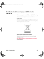
1
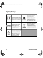
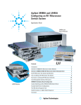
U2931A Operating Guide.book
Page 1
Tuesday, October 14, 2014
11:54 PM
Keysight U2121A-101 RF
Switch Driver Board
Operating
Guide
U2931A Operating Guide.book
Page 2
Tuesday, October 14, 2014
11:54 PM
U2931A Operating Guide.book
Page I
Tuesday, October 14, 2014
11:54 PM
U2931A Operating Guide.book
Page II
Tuesday, October 14, 2014
11:54 PM
Notices
® Keysight Technologies 2008 - 2014
Warranty
No part of this manual may be reproduced in
any form or by any means (including electronic storage and retrieval or translation
into a foreign language) without prior agreement and written consent from Keysight
Technologies as governed by United States
and international copyright laws.
The material contained in this document is provided “as is,” and is subject to being changed, without notice,
in future editions. Further, to the maximum extent permitted by applicable
law, Keysight disclaims all warranties, either express or implied, with
regard to this manual and any information contained herein, including
but not limited to the implied warranties of merchantability and fitness for
a particular purpose. Keysight shall
not be liable for errors or for incidental or consequential damages in connection with the furnishing, use, or
performance of this document or of
any information contained herein.
Should Keysight and the user have a
separate written agreement with
warranty terms covering the material
in this document that conflict with
these terms, the warranty terms in the
separate agreement shall control.
Manual Part Number
U2931-90001
Edition
Edition 3, November 2014
Keysight Technologies
1400 Fountaingrove Parkway
Santa Rosa, CA 95403
Trademark Acknowledgements
Pentium is a U.S. registered trademark of
Intel Corporation.
Microsoft, Visual Studio, Windows, and MS
Windows are trademarks of Microsoft Corporation in the United States and/or other
countries.
Technology Licenses
The hardware and/or software described in
this document are furnished under a license
and may be used or copied only in accordance with the terms of such license.
Restricted Rights Legend
U.S. Government Restricted Rights. Software and technical data rights granted to
the federal government include only those
rights customarily provided to end user customers. Keysight provides this customary
commercial license in Software and technical data pursuant to FAR 12.211 (Technical
Data) and 12.212 (Computer Software) and,
for the Department of Defense, DFARS
252.227-7015 (Technical Data - Commercial
Items) and DFARS 227.7202-3 (Rights in
Commercial Computer Software or Computer Software Documentation).
II
Safety Notices
CAUTION
A CAUTION notice denotes a hazard. It calls attention to an operating procedure, practice, or the like
that, if not correctly performed or
adhered to, could result in damage
to the product or loss of important
data. Do not proceed beyond a
CAUTION notice until the indicated
conditions are fully understood and
met.
WA R N I N G
A WARNING notice denotes a
hazard. It calls attention to an
operating procedure, practice, or
the like that, if not correctly performed or adhered to, could result
in personal injury or death. Do not
proceed beyond a WARNING
notice until the indicated conditions are fully understood and
met.
U2121A-101 Operating Guide
U2931A Operating Guide.book
Page III
Tuesday, October 14, 2014
11:54 PM
Safety Symbols
The following symbols on the instrument and in the documentation
indicate precautions, which must be taken to maintain safe operation of
the instrument.
Direct current (DC)
Equipment protected throughout by
double insulation or reinforced
insulation
Alternating current (AC)
Off (supply)
Both direct and alternating current
On (supply)
Three-phase alternating current
Caution, risk of electric shock
Earth (ground) terminal
Caution, risk of danger (refer to this
manual for specific Warning or Caution
information)
Protective conductor terminal
Caution, hot surface
Frame or chassis terminal
Out position of a bi-stable push control
Equipotentiality
In position of a bi-stable push control
U2121A-101 Operating Guide
III
U2931A Operating Guide.book
Page IV
Tuesday, October 14, 2014
11:54 PM
General Safety Information
WA R N I N G
• Do not load the output terminals above the specified current limits.
• Do not use the device if it appears damaged or defective.
• Observe all markings on the device before connecting any wiring to
the device.
• Do no operate the device in the presence of flammable gases or
fumes.
• Do no install substitute parts or perform any unauthorized
modification to the device.
CAUTION
• Applying excessive voltage or overloading the device will cause
irreversible damage to the circuitry.
• Use the device with the cables provided.
• Repair or service that is not covered in this manual should only be
performed by qualified personnels.
• To avoid ESD damage to the RF switch driver board, users are highly
recommended to comply with the following cautions:
• User are required to discharge themselves to any large metal object
(e.g. Shelf, desk, etc.) prior to operating the RF switch driver board.
• Operate the RF switch driver board under an ESD protected workstation,
with the minimum requirements of using wrist strap (connected to ground)
and ESD pad. The wrist strap can be grounded by connecting to the power
supply ground and/or circuit board ground.
• Avoid human body contact or a charged material to the on-board components
and circuitries. Always hold the board edges when carrying the RF switch driver
board.
IV
U2121A-101 Operating Guide
U2931A Operating Guide.book
Page V
Tuesday, October 14, 2014
11:54 PM
Environmental Conditions
This instrument is designed for indoor use and in an area with low
condensation. The table below shows the general environmental
requirements for this instrument.
CAUTION
Requirements
Operating temperature
0 °C to 40 °C
Storage temperature
–40 °C to 70 °C
Operating humidity
Up to 85% at 40 °C (non-condensing)
Storage humidity
5% to 90% RH (non-condensing)
The U2121A-101 RF switch driver board complies with the following safety
and EMC requirements.
•
•
•
•
U2121A-101 Operating Guide
Environmental conditions
IEC 61326-2002/EN 61326:1997+A1:1998+A2:2001+A3:2003
Canada: ICES-001:2004
Australia/New Zealand: AS/NZS CISPR11:2004
IEC 61010-1:2001/EN 61010-1:2001 (2nd edition)
V
U2931A Operating Guide.book
Page VI
Tuesday, October 14, 2014
11:54 PM
Regulatory Markings
The CE mark is a registered trademark
of the European Community. This CE
mark shows that the product complies
with all the relevant European Legal
Directives.
ICES/NMB-001 indicates that this
ISM device complies with the
Canadian ICES-001.
Cet appareil ISM est confomre a la
norme NMB-001 du Canada.
The C-tick mark is a registered
trademark of the Spectrum
Management Agency of Australia.
This signifies compliance with
the Australia EMC Framework
regulations under the terms of the
Radio Communication Act of 1992.
This instrument complies with the
WEEE Directive (2002/96/EC)
marking requirement. This affixed
product label indicates that you must
not discard this electrical/electronic
product in domestic household waste.
This symbod indicates that a device,
or part of a device, may be susceptible
to electrostatic discharges (ESD),
which can result in damage to the
product. Observe ESD precautions
given on the product, or its user
documentation, when handling
equipment bearing this mark.
VI
U2121A-101 Operating Guide
U2931A Operating Guide.book
Page VII
Tuesday, October 14, 2014
11:54 PM
Waste Electrical and Electronic Equipment (WEEE) Directive
2002/96/EC
This instrument complies with the WEEE Directive (2002/96/EC) marking
requirement. This affixed product label indicates that you must not discard
this electrical/electronic product in domestic household waste.
Product Category:
With reference to the equipment types in the WEEE directive Annex 1, this
instrument is classified as a “Monitoring and Control Instrument” product.
The affixed product label is shown as below.
Do not dispose in domestic household waste
To return this unwanted instrument, contact your nearest Keysight
Technologies, or visit:
http://about.keysight.com/en/companyinfo/environment/takeback.shtml
for more information.
U2121A-101 Operating Guide
VII
U2931A Operating Guide.book
Page VIII Tuesday, October 14, 2014
11:54 PM
DECLARATION OF CONFORMITY
According to EN ISO/IEC 17050-1:2004
Generic example
Manufacturer’s Name:
Manufacturer’s Address:
Agilent Technologies Microwave Products (M) Sdn. Bhd
Bayan Lepas Free Industrial Zone,
11900, Bayan Lepas, Penang, Malaysia
Declares under sole responsibility that the product as originally delivered
Product Name:
Models Number:
Product Options:
Agilent RF Switch Board
U2931A
This declaration covers all options of the above product(s)
complies with the essential requirements of the following applicable European Directives, and
carries the CE marking accordingly:
Low Voltage Directive (2006/95/EC)
EMC Directive (2004/108/EC)
and conforms with the following product standards:
EMC
IEC 61326:2002 / EN 61326:1997+A1:1998+A2:2001+A3:2003
CISPR 11:1990 / EN55011:1990
IEC 61000-4-2:1995 / EN 61000-4-2:1995
IEC 61000-4-3:1995 / EN 61000-4-3:1996
IEC 61000-4-4:1995 / EN 61000-4-4:1995
IEC 61000-4-5:1995 / EN 61000-4-5:1995
IEC 61000-4-6:1996 / EN 61000-4-6:1996
IEC 61000-4-11:1994 / EN 61000-4-11:1994
Class A Group 1
4 kV CD, 8 kV AD
3 V/m, 80-1000 MHz
0.5 kV signal lines, 1 kV power lines
0.5 kV line-line, 1 kV line-ground
3 V, 0.15-80 MHz
1 cycle / 100%
Canada: ICES-001:2004
Australia/New Zealand: AS/NZS CISPR11:2004
The product was tested in a typical configuration with Agilent Technologies test systems.
Safety
IEC 61010-1:2001 / EN 61010-1:2001
Additional Information:
The U2931A receives power from an AC/DC power supply model DSA-60W-20 1 24060.
This DoC applies to above-listed products placed on the EU market after:
31-March-2008
Tay Eng Su
Date
Quality Manager
For further information, please contact your local Agilent Technologies sales office, agent or distributor,
or Agilent Technologies Deutschland GmbH, Herrenberger Straße 130, 71034 Böblingen, Germany.
Template: A5971-5302-2, Rev. E
VIII
U2931A
DoC Revision 1.0
U2121A-101 Operating Guide
U2931A Operating Guide.book
Page IX
Tuesday, October 14, 2014
11:54 PM
Product Regulations
Performance Criteria
IEC 61326-1:2002 / EN 61326-1:1997+A1:1998+A2:2001+A3:2003
CISPR 11:1990 / EN 55011:1990 – Group 1 Class A
IEC 61000-4-2:1995 / EN 61000-4-2:1995 (ESD 4kV CD, 8kV AD)
IEC 61000-4-3:1995 / EN 61000-4-3:1996 (3V/m, 80% AM)
IEC 61000-4-4:1995 / EN 61000-4-4:1995 (EFT 0.5kV line-line, 1kV line-earth)
IEC 61000-4-5:1995 / EN 61000-4-5:1995 (Surge 0.5kV line-line, 1kV line-earth)
IEC 61000-4-6:1996 / EN 61000-4-6:1996 (3V, 0.15~80 MHz, 80% AM, power line)
IEC 61000-4-11:1994 / EN 61000-4-11:1994 (Dips 1 cycle, 100%)
A
A
A
A
A
A
Canada: ICES-001:2004
Australia/New Zealand: AS/NZS CISPR11:2004
IEC 61010-1:2001 / EN 61010-1:2001
Additional Information:
The product herewith complies with the essential requirements of the Low Voltage Directive 2006/95/EC and the
EMC Directive 2004/108/EC and carries the CE Marking accordingly (European Union).
1
Performance Criteria:
A Pass - Normal operation, no effect.
B Pass - Temporary degradation, self recoverable.
C Pass - Temporary degradation, operator intervention required.
D Fail - Not recoverable, component damage.
N/A – Not applicable
Notes:
Regulatory Information for Canada
ICES/NMB-001:2004
This ISM device complies with Canadian ICES-001.
Cet appareil ISM est confomre à la norme NMB-001 du Canada.
Regulatory Information for Australia/New Zealand
This ISM device complies with Australian/New Zealand AS/NZS CISPR11:2004
U2121A-101 Operating Guide
IX
U2931A Operating Guide.book
X
Page X
Tuesday, October 14, 2014
11:54 PM
U2121A-101 Operating Guide
U2931A Operating Guide.book
Page 1
Tuesday, October 14, 2014
11:54 PM
Contents
Introduction 2
Standard Purchase Items Checklist 4
Product at a Glance 5
Product outlook 5
Product dimensions 6
Connector Pins Configuration 7
Installation Guide 10
A. Check your system 11
B. Install prerequisites and software 12
C. Connect the hardware solution to your PC 14
D. Launch the Keysight U2121A-Based RF Switch Driver Software 15
Supported Switches 19
Product Characteristics and Specifications 21
Maintenance 23
Disassemble Procedure 24
Ordering Info 26
Optional accessory 26
Appendix A: Control Instructions 29
Appendix B: Y1157A Cable Assembly Instructions 31
U2121A-101 Operating Guide
1
U2931A Operating Guide.book
Page 2
Tuesday, October 14, 2014
11:54 PM
Introduction
The Keysight U2121A- 101 (also known as U2931A) RF switch driver
with cable is an adapter board designed for use with the Keysight
U2121A digital IO device. It enables you to control various types of
RF switches easily and has enhanced driving capability and consists
of different types of connectors to suit different switches.
The U2121A- 101 purchase consists of a driver interface module, an
interface cable (equipped with a 37- pin D- sub connector on one end
and four 10- way terminal block connectors on the other end), a
10- pin to D- sub adapter, and a 24 VDC, 2.5 A power adapter. This
module is connected to the U2121A using the provided interface
cable. You can also use the Y1157A[1] cable, which is a 10- pin ribbon
connector to 9- pin D- Sub cable kit for the Keysight N1810/11/12
coaxial switches.
This module is consists of five RF switch driver channels and one
general IO terminal. Each channel is pre- programmed to drive three
different types of Keysight RF switches. Only one type of RF switch
can be connected to a single channel during operation.
CAUTION
DO NOT connect different types of RF switches to the same channel during
operating time.
The U2121A- 101 module is designed to handle 24 VDC switches.
[1] Refer to Appendix B for Y1157A cable kit assembly.
2
U2121A-101 Operating Guide
U2931A Operating Guide.book
Page 3
Tuesday, October 14, 2014
11:54 PM
Power supply
The switches on this module are powered by the provided power
adapter. There is only one power supply voltage available for this
module, which is 24 VDC, 2.5 A.
Power consumption
The U2121A- 101 can drive up to 1500 mA continuously using the
provided power supply. For each channel, it is able to drive up to 300
mA load per switch. Precaution must be taken to ensure that the
total current consumption on all channels is not more than 1500 mA,
which is the maximum driving capability of the module.
U2121A-101 Operating Guide
3
U2931A Operating Guide.book
Page 4
Tuesday, October 14, 2014
11:54 PM
Standard Purchase Items Checklist
Verify that you have received the following items with your purchase.
U2121A- 101 RF switch driver board with cable purchase. If anything is
missing or damaged, please contact the nearest Keysight Sales Office.
✔ RF switch driver board
✔ RF switch driver board interface
✔ U2931- 60013 10 ways IDC to 9- pins D- Sub adapter
✔ U2931- 60012 power adapter
✔ Keysight U2121A- 101 RF Switch Driver Board Operating Guide
✔ Keysight U2931A RF Switch Driver Product Reference CD- ROM
4
U2121A-101 Operating Guide
U2931A Operating Guide.book
Page 5
Tuesday, October 14, 2014
11:54 PM
Product at a Glance
Product outlook
Top view (without casing)
Connector for
8765x-024 RF switches
Connector for 8762/3/4
8765x/324 RF switches
Connector for
general I/O
Connector for
general output
Connector for
general input
DC power jack
U2121A-101 Operating Guide
Power
rating
Digital IO
terminal
Connector for
N181x RF switches
5
U2931A Operating Guide.book
Page 6
Tuesday, October 14, 2014
11:54 PM
Product dimensions
Top view (without casing)
72.00 mm
150.00 mm
Top view (with casing)
85.00 mm
153.00 mm
Front view (with casing)
Side view (with casing)
38.00 mm
6
85.00 mm
U2121A-101 Operating Guide
U2931A Operating Guide.book
Page 7
Tuesday, October 14, 2014
11:54 PM
Connector Pins Configuration
Pin out configuration for all terminals
Table 1
Table 2
Table 3
U2121A-101 Operating Guide
8762/2/3 and 8765x-324 Series switches (X1 to X5)
Pin
Function
1
Position #1
2
Position #2
3
N.C.
4
+24 V
8765x-024 Series switches (SL1 to SL5)
Pin
Function
1
Position #2
2
N.C.
3
+24 V
4
+24 V
5
Position #1
N181X Series switches (SV1 to SV5)
Pin
Function
Pin
Function
1
GND
2
+5 V
3
N.C.
4
Indicator B
5
Position B
6
+5 V
7
Position A
8
Indicator A
9
+24 V
10
N.C.
7
U2931A Operating Guide.book
Page 8
Tuesday, October 14, 2014
11:54 PM
IO mapping
There are three main control bits used in the U2121A- 101 as shown
in tables below. These control bits also refers to the U2121A control
bit status.
Table 4
Output enable/disable control
Control Stage
Control Bit, DO14
Description
Output disabled
OFF (0)
To disable all outputs in U2121A- 101
Output enabled
ON (0)
To enable all outputs in U2121A- 101
Table 5
Position information read back control
RF Switches
WA R N I N G
8
Control Bit
Description
D16
D15
8765x and 8762/3/4
OFF (0)
ON (1)
Read position information from 8765x and
8762/3/4 series switches
N181x
ON (1)
OFF (0)
Read position information from N181x
series switches
DO NOT set both D15 and D16 control bits to ON stage!
U2121A-101 Operating Guide
U2931A Operating Guide.book
Page 9
Tuesday, October 14, 2014
11:54 PM
Each of the five RF switch channels uses two digital output pins and
two digital input pins during the operation.
Table 6a
IO mapping for 8762/3/4, 8765x-324 and N181x Series RF switches
Channel
Control Bit
State A
State B
State A
State B
1
O1
O2
I1
I2
2
O3
O4
I3
I4
3
O5
O6
I5
I6
4
O7
O8
I7
I8
5
O9
O10
I9
I10
General IO
Table 6b
O11, O12 & O13
I11, I12 & I13
IO mapping for 8765x-024 Series RF switches
Channel
Control Bit
Position Bit
State A
State B
State A
State B
1
O2
O1
I2
I1
2
O4
O3
I4
I3
3
O6
O5
I6
I5
4
O8
O7
I8
I7
5
O10
O9
I10
I9
General IO
Table 7
Position Bit
O11, O12 & O13
I11, I12 & I13
Position indicator stage definition
RF Switches Model
Activated
Deactivated
8732/3/4 Series and 875x Series
OFF (0)
ON (1)
N181x Series
ON (1)
OFF (0)
U2121A-101 Operating Guide
9
U2931A Operating Guide.book
Page 10
Tuesday, October 14, 2014
11:54 PM
Installation Guide
Follow the step- by- step instructions shown in the following flowchart
to get started with the preparations and installations of your Keysight
U2121A- Based RF Switch Driver Software.
NOTE
You need to install the IVI-COM driver if you are going to use the U2121A- 101
with Keysight VEE Pro, LabVIEW, or Microsoft® Visual Studio®.
A. Check your system
B. Install prerequisites and software
C. Connect the hardware solution to your PC
D. Launch the Keysight U2121A-Based RF
Switch Driver Software
10
U2121A-101 Operating Guide
U2931A Operating Guide.book
Page 11
Tuesday, October 14, 2014
11:54 PM
A. Check your system
Prior to any installation or configuration, please ensure that your PC
meets the following minimum system requirements.
Hardware requirements
Hardware required
Specification (minimum)
Processor
1.6 GHz Pentium® IV or higher
Operating System
Windows® XP Professional or Home Edition (Service Pack
1 or later), or Windows® 2000 Professional (Service Pack
4 or later)
Video
1024×768 recommended
Browser
Microsoft® Internet Explorer 5.01 or higher (6.0 or higher
recommended)
Available RAM
128 MB or higher (256 MB or higher recommended)
Hard Disk Space
1 GB required for installation
Software requirements
NOTE
Software required
Version (minimum)
Keysight VEE Pro Runtime
Version 8.5[1]
Keysight U2121 IVI Driver
Version 1.0.9.0[1]
Keysight IO Libraries Suite
Version 15.0[2] or higher
Microsoft® .NET Framework
Version 1.1 and 2.0[1]
Keysight IO Libraries Suite 15.0 is required if your PC is running on Microsoft®
Windows Vista™ 32-bit operating system.
[1] Bundled with Keysight U2121A-Based RF Switch Driver Software installer.
[2] Obtained from Keysight Automation-Ready CD.
U2121A-101 Operating Guide
11
U2931A Operating Guide.book
Page 12
Tuesday, October 14, 2014
11:54 PM
B. Install prerequisites and software
There are two options you may choose from to install the
prerequisites and Keysight U2121A- Based RF Switch Driver Software.
You may choose to install from the provided Product Reference
CD- ROM or obtain the installation software from Keysight's website to
install the software.
NOTE
Prior to installing the prerequisites and Keysight U2121-Based RF Switch
Driver Software, ensure that your PC meets the minimum system
requirements for installation and operation processes.
Installing the application software from CD
1 Disconnect any instrument that is connected to your PC and close
all other applications on your PC.
2 Insert the Product Reference CD- ROM into your CD- ROM drive.
3 The installer will automatically launch the Keysight U2121A- Based
Installation Menu. Click Application to begin installation of the
following items:
i Microsoft .NET Framework 2.0
ii Keysight VEE Pro 8.5 Runtime
iii Keysight U2121 IVI Driver
iv Keysight U2121A- Based RF Switch Driver Software
12
U2121A-101 Operating Guide
U2931A Operating Guide.book
Page 13
Tuesday, October 14, 2014
11:54 PM
4 If the installation menu does not appear after a few seconds, go to
Start > Run and type <drive>:\Application\setup.exe where
<drive> is your CD- ROM drive location.
5 Click OK to begin the installation of the following items.
6 If you do not have any of the prerequisites installed, the
InstallShield Wizard software prerequisite will appear.
7 Click OK to begin the installation of the listed missing
prerequisites.
8 Once the above installation has completed, installation of the
U2121A- Based RF Switch Driver Software will proceed as normal.
9 The Keysight RF Switch Driver InstallShield Wizard dialog will appear.
Click Next to begin.
10 Read the License Agreement and select I accept the terms in the License
Agreement to proceed. You may click Print to print a hardcopy of the
Keysight License Terms for your reference. Click Next to proceed.
11 Fill in the Customer Information Form accordingly, and click Next.
12 Click Next to install to the specified folder or click Change to install
to a different folder.
13 Click Install to begin the installation of the U2121A- Based RF
Switch Driver Software.
14 Click Finish when the installation has completed.
15 A shortcut to this software will be created to your desktop.
NOTE
USING THE LICENSED MATERIALS INDICATES YOUR ACCEPTANCE OF THE
LICENSE TERMS. IF YOU DO NOT AGREE TO ALL OF THESE TERMS, YOU
MAY RETURN ANY UNOPENED LICENSED MATERIAL FOR A FULL REFUND,
IF THE LICENSED MATERIALS ARE BUNDLED OR PRE-LOADED WITH
ANOTHER PRODUCT, YOU MAY RETURN THE ENTIRE UNUSED PRODUCT
FOR A FULL REFUND.
Downloading the application software from the Web
1 Go to http://www.keysight.com/find/DIOsolution/, and download the
Keysight U2121A- Based RF Switch Driver Software.
2 Save the file to any location on your hard disk.
U2121A-101 Operating Guide
13
U2931A Operating Guide.book
Page 14
Tuesday, October 14, 2014
11:54 PM
3 Disconnect any instrument that is connected to your PC and close
all other applications on your PC.
4 Double- click the saved installation file to begin installation.
5 If you do not have any of the prerequisites installed, the InstallShield
Wizard software prerequisite will appear.
6 Click OK to begin the installation of the listed missing
prerequisites.
7 Once the above installation has completed, installation of the
Keysight U21210A- BAsed RF Switch Driver Software will proceed
as normal.
8 Follow the instructions on your screen to begin the installation.
9 Click Finish once the installation has completed.
C. Connect the hardware solution to your PC
1 Connect the U2121A- 101 board digital IO terminal to the U2121A
terminal block using the interface cable.
2 Connect the power adapter to the RF switch driver board’s DC
power jack.
3 Connect the RF switches as below:
i For 8762/3/4 and 8765x- 324 RF switches, connect to any SL1[1]
to SL5[1] slot.
ii For 8765x- 024 RF switches, connect to any X1[2] to X5[2] slot.
iii For N181x RF switches, connect to any SV1[3] to SV5[3] slot.
NOTE
Connect only one type of the RF switch to one channel. Do not use multiple
switches simultaneously on one channel.
4 Connect other types of load to general IO, X7[4] or X8[5] and X9[6]
if required. The load voltage is 24 VDC. The maximum load should
not exceed 300 mA per output channel and 3 mA per input
channel.
14
U2121A-101 Operating Guide
U2931A Operating Guide.book
Page 15
WA R N I N G
Tuesday, October 14, 2014
11:54 PM
The total allowable current is 1500 mA. Please ensure that the total current
consumption is not more than 1500 mA.
[1] SL1 to SL5 refers to the 8762/3/4 and 8765x-324 RF switch connectors for Ch1 to Ch5.
[2] X1 to X5 refers to the 8765x-024 RF switch connectors for Ch1 to Ch5.
[3] SV1 to SV5 refers to the N181x RF switch connectors for Ch1 to Ch5.
[4] X7 refers to the connector for general I/O on the switch driver board.
[5] X8 refers to the connector for general output on the switch driver board.
[6] X9 refers to the connector for general input on the switch driver board.
D. Launch the Keysight U2121A-Based RF Switch Driver
Software
NOTE
Before you proceed, ensure that your system meets the minimum system
requirements.
1 Before attempting to start- up your U2121A- Based RF Switch Driver
Software, it is recommended to follow the step- by- steps
instructions below.
2 Plug in your instrument via the supported USB socket.
3 Go to Start > All Programs > Keysight IO Libraries Suite > Keysight
Connection Expert to launch the Connection Expert.
4 The detected U2121A will be visible on the Instrument I/O on this PC
explorer pane. Right- click on the U2121A instrument on the
explorer pane.
5 A context menu will appear as shown below. Select Send Commands
To This Instrument.
U2121A-101 Operating Guide
15
U2931A Operating Guide.book
Page 16
Tuesday, October 14, 2014
11:54 PM
6 The Keysight Interactive IO dialog box will appear. Click Send & Read
to send the *IDN? default command. The instrument’s response
should appear in the Instrument Session History panel.
7 If the Connection Expert can successfully communicate with the
U2121A, this indicates that the instrument has been installed
correctly.
NOTE
• The IO Control will launch automatically when you start your PC.
• Launching the VEE without the IO Control running will cause failure of the
VEE to detect or establish any connection with the U2121A connected to
your PC.
• To run the IO Control, go to Start > All Programs > Keysight IO Libraries
Suite > Utilities > IO Control.
16
U2121A-101 Operating Guide
U2931A Operating Guide.book
Page 17
Tuesday, October 14, 2014
11:54 PM
8 Double- click Keysight U2121A-Based RF Switch Driver Software icon on
your desktop or go to Start > All Programs > Keysight U2121A-Based RF
Switch Driver > U2121A-Based RF Switch Driver Software to launch the
software.
9 The U2121A- Based RF Switch Driver Software screen will appear.
10 To start the application, click on the Start button. The Select USB
Device dialog box will appear displaying the connected U2121A
devices. Select a U2121A device and click on it to establish the
connection.
11 Select the switch type corresponding to the connected switch on
each channel.
U2121A-101 Operating Guide
17
U2931A Operating Guide.book
Page 18
Tuesday, October 14, 2014
11:54 PM
12 Use the toggle paddle for each channel in the program to select
respective switch position.
13 Use the checkbox and the Send Output button in the General Output
section to control the output devices connected to the RF switches.
14 To view the General Input Status, click the Refresh Input Status Bits
button in the General Input section.
15 Click Exit to leave the program, all switches will be disabled upon
exiting the program.
NOTE
18
Refer to the Keysight U2121A-Based RF Switch Driver Software Help File for more
information.
U2121A-101 Operating Guide
U2931A Operating Guide.book
Page 19
Tuesday, October 14, 2014
11:54 PM
Supported Switches
The U2121A- 101A supports three types of Keysight RF switches as
shown in Table 9. User can choose to drive the same switches in all
five channels or a mixture of three switches for five channels.
However, only one type of switch can be used in a channel at a time.
Do not use multiple types of switches in the same channel.
Drive modes
The RF switch driver board drives the switches using the open
collector drive method. It provides a current path to the ground when
asserted.
H
DO
Channel
L
Drive activated
Continuous Drive
Continuous drive method controls the switches by activating the
control bit and holds it until it is disabled. This mode will have a
consistent current draw when the switch is activated.
Output
enable
Drive ChA
Drive active
Drive ChB
Drive active
U2121A-101 Operating Guide
19
U2931A Operating Guide.book
Page 20
Tuesday, October 14, 2014
11:54 PM
Pulse drive
Pulse drive method controls the switches using a ~30 ms pulse. As
shown in the figure below, the control signal is applied to one of the
control bit and held for the preset time.
Output
enable
Drive ChA
Drive active
Drive ChB
Drive active
General IO
There are three digital outputs and three digital inputs available in
the U2121A- 101 as an auxiliary port. These three output pins are
capable to drive up to 300 mA of load. The digital input pin has a
direct connection to the U2121A.
Controlled supply
Output
From U2121A DO
Input
To U2121A DI
Output circuit
20
Input circuit
U2121A-101 Operating Guide
U2931A Operating Guide.book
Page 21
Tuesday, October 14, 2014
11:54 PM
Product Characteristics and Specifications
Table 8
General characteristics of the U2121A-101 RF switch driver board
General Characteristics
Power consumption
• +24 VDC, 2.5 A
• Isolated ELV supply source
Operating environment
0 °C to 40 °C
Storage temperature
–40 °C to 70 °C
Operating humidity
Up to 85% at 40 °C (non-condensing)
Storage humidity
5% to 90% RH (non-condensing)
EMC
• IEC61326-2002/EN61326:1997+A1:1998+A2:2001+A3:2003
• Canada: ICES-001:2004
• Australia/New Zealand: AS/NZS CISPR11:2004
Safety
IEC 61010-1:2001/EN 61010-1:2001 (2nd edition)
Driving current per channel
300 mA (max)
Total current
1500 mA (max)
IO channels for RF switch
5 channels
Generic IO
3 digital inputs and 3 digital outputs
Board dimension (W x D)
150 mm x 72 mm
Casing dimension (W x D x H)
153 mm x 85 mm x 38 mm
Weight
• With casing: 146 g
• Without casing: 86 g
Warranty
One year
U2121A-101 Operating Guide
21
U2931A Operating Guide.book
Table 9
Page 22
Tuesday, October 14, 2014
11:54 PM
Type of switches supported by U2121A-101 RF switch driver board
Switch/Attenuator
Reference
Document No.
Coil Voltage
Connection Type
Drive Options
Option 124
24 VDC
Option 201
D-Sub 9-pin female
Option 402
Position Indicators
Option 024
24 VDC
Solder Lugs
STD
Direct coil for open drain
Keysight N1810/11/12 Coaxial Switches
N1810UL/TL
N1811TL
N1812TL
5968-9653E
Keysight 8762/63/64 Coaxial Switches
8762A/B/C/F
8763A/B/C
8764A/B/C
5952-1873E
Keysight Microwave SPDT Switches
8765A/B/C/D
5952-2231E
Option 324
24VDC
Solder Terminals
STD
Direct coil for open drain
8765A/B/C/D
5952-2231E
Option 024
24 VDC
Ribbon cable terminated
with single in-line
STD
Direct coil for open drain
22
U2121A-101 Operating Guide
U2931A Operating Guide.book
Page 23
Tuesday, October 14, 2014
11:54 PM
Maintenance
1 Power off your device, unplug the DC power jack and remove the
RF switch driver board interface cable from your device.
2 Remove your device from the plastic casing.
3 Shake out any dirt that may have accumulated on the RF switch
driver board.
4 Wipe your RF switch driver board with a dry cloth and install the
plastic casing back in place.
U2121A-101 Operating Guide
23
U2931A Operating Guide.book
Page 24
Tuesday, October 14, 2014
11:54 PM
Disassemble Procedure
The following steps shows the disassemble procedure of the RF switch
driver board from its casing.
1 Remove the two screws on either side of the board.
2 Remove the side panel from the casing.
24
U2121A-101 Operating Guide
U2931A Operating Guide.book
Page 25
Tuesday, October 14, 2014
11:54 PM
3 Remove the PCA from the casing.
4 The disassembled RF switch driver board is shown below.
U2121A-101 Operating Guide
25
U2931A Operating Guide.book
Page 26
Tuesday, October 14, 2014
11:54 PM
Ordering Info
To order the U2931A RF switch driver, please select the U2121A and
U2121A–101 ordering options. This will include the U2121A digital IO
device and U2121A–101 RF switch driver board and cable. You can
also order the U2931A RF switch driver board as a standalone unit
by choosing the U2931A–101 ordering option.
Table 10
RF switch driver board ordering options
Ordering Option
(with U2121A)
1
Ordering Option
(as standalone)
Description
U2931A–101
U2121A–101 RF switch driver board
U2931A–102
U2121A–101 RF switch driver board cable
U2121A-–01
2
Optional accessory
Table 11
1
26
RF switch driver board optional accessory
Ordering Options
Description
Y1157A
9-to-10 pin extension cable for N181x — supplies to build 4 cables
U2121A-101 Operating Guide
U2931A Operating Guide.book
Page 29
Tuesday, October 14, 2014
11:54 PM
Appendix A: Control Instructions
The COM driver minimum system requirements are as shown below.
Minimum System Requirements
PC hardware
450 MHz Pentium II or higher, 128 MB RAM, 40 GB hard disk
space, CD-ROM drive.
Operating system
Windows® XP Professional or Home Edition, Service Pack 1 or
later, Windows® 2000 Professional, Service Pack 4 or later.
Software driver
IVI-COM
Compatible with
programming
environments
•
Keysight VEE
•
Microsoft® Visual Studio.NET, C/C++
•
Microsoft® Visual Basic 6/7
•
LabVIEW
Please adhere to the following instructions strictly to create the COM
driver.
To read digital input information.
1 When reading digital input, set the desired channel to ON (1) and
then read the target bit. Set the channel back to OFF (0) when the
information has been read.
2 Do not activate both Ch15 and Ch16 at the same time because this
will cause an excessive current flow; which will result in a sudden
temperature increase in the buffer IC and regulator IC.
NOTE
Prolonged exposure to increased temperature will cause overheating in your buffer IC
and regulator IC.
U2121A-101 Operating Guide
29
U2931A Operating Guide.book
Page 30
Tuesday, October 14, 2014
11:54 PM
To set digital output.
1 To enable digital output control, set Ch14 to ON (1).
2 For channel 1 to channel 5, only activated one bit at a time. Do
not activate both bits together because this will damage your RF
switches.
3 Some RF switches will need pulse current control instead of
continuous current control. Please refer to the respective RF
switches' datasheets for more information. The wrong control
method will lead to RF switch damage.
NOTE
• Prolonged exposure to a continuous supplied current will cause overheating in
your RF switch. Please ensure your devices temperatures are constantly
monitored when supplying continuous current.
• Refer to the Keysight U2121A-Based RF Switch Driver COM Object Help File for
more information.
30
U2121A-101 Operating Guide
U2931A Operating Guide.book
Page 31
Tuesday, October 14, 2014
11:54 PM
Appendix B: Y1157A Cable Assembly Instructions
The Y1157A is a 10- pin ribbon connector to 9- pin D- Sub cable kit
which contains materials to build four cables.
The key to building the cables correctly is to understand the
orientation of the socket pins on the distribution boards and the pin
number orientation of the cable connectors. This orientation is shown
in Figure B- 1. When using the D- sub connector, always refer to the
pin orientation shown in Figure B- 1. Do not use the pin numbers
printed on the part.
Distribution board
connector (10-pin)
Ribbon connector (10-pin)
D-Sub connector (9-pin)
Figure B-1 Distribution board socket and Y1157A cable connector Orientation
The steps for building the cables are as follows:
1 Cut the ribbon cable slightly longer than the desired length.
2 Position the D- Sub connector and the ribbon cable connector as
shown in Figure B- 2. Route the cable through the connectors,
noting the location of cable pin 1. By convention, pin 1 is indicated
in red (the dark line in the drawing).
U2121A-101 Operating Guide
31
U2931A Operating Guide.book
Page 32
Tuesday, October 14, 2014
Strain relief
11:54 PM
Pin 1 of ribbon cable
Align connector contacts
over cable lines
“Press” until metal contacts are no longer
visible (same for D-Sub connector)
Figure B-2 Y1157A connector orientation and ribbon cable routing
3 Move the connectors to the ends of the cable, allowing for some
overlap on the D- Sub connector end and strain relief on the ribbon
cable connector end. Note the orientation of the connectors and
cable in Figure B- 2.
4 Align the metal contacts of the ribbon connector over cable pin 1
(Figure B- 2) and the other pins, press the ribbon cable connector
onto the cable using a vise or clamp to press the contacts evenly
through the cable insulation. Continue to press the connector until
the metal contacts are no longer visible.
5 Fasten the strain relief clamp over the cable and into the ribbon
cable connector as shown in Figure B- 2. Remove any excess cable
after the clamp is in place.
6 Align the metal contacts of the D- Sub connector over cable pin 1
and the other pins, press the D- Sub connector onto the cable using
a vise or clamp to press the contacts evenly through the cable
insulation. Continue to press the connector until the metal contacts
are no longer visible. Remove any excess cable after the connector
is in place.
32
U2121A-101 Operating Guide
U2931A Operating Guide.book
Page 33
Tuesday, October 14, 2014
11:54 PM
www.keysight.com
Contact us
To obtain service, warranty or technical assistance, contact us at the following phone or fax
numbers:
United States:
(tel) 800 829 4444
(fax) 800 829 4433
Canada:
(tel) 877 894 4414
(fax) 800 746 4866
China:
(tel) 800 810 0189
(fax) 800 820 2816
Europe:
(tel) 31 20 547 2111
Japan:
(tel) (81) 426 56 7832 (fax) (81) 426 56 7840
Korea:
(tel) (080) 769 0800
(fax) (080) 769 0900
Latin America:
(tel) (305) 269 7500
Taiwan:
(tel) 0800 047 866
(fax) 0800 286 331
Other Asia Pacific Countries:
(tel) (65) 6375 8100
(fax) (65) 6755 0042
Or visit Keysight World Wide Web at:
www.keysight.com/find/assist
Product specifications and descriptions in this
document are subject to change
without notice. Always refer to Keysight web
site for the latest revision.
U2931A Operating Guide.book
Page 1
Tuesday, October 14, 2014
11:54 PM
This information is subject to change without notice.
© Keysight Technologies 2008 - 2014
Edition 3, November 2014
*U2931-90001*
U2931-90001
www.keysight.com