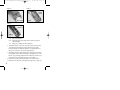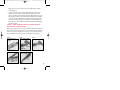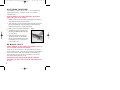
1
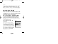
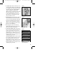
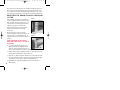
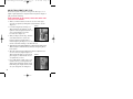
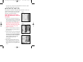
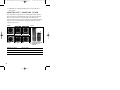
8/11/03
11:53 AM
The Best There Is
™
02-260-BFA_Revised BT99 OM_Cvr
BT-99
TRAP SHOTGUN
O W N E R ’ S
M A N U A L
Page 2
02-260-BFA_Revised BT99 OM
8/11/03
11:48 AM
Page 1
THANK YOU FOR CHOOSING A BROWNING
B T- 9 9 T R A P S H O T G U N .
We are pleased that you have chosen a Browning BT-99 Trap
shotgun. In every way it is a firearm you will be proud to shoot
for many years. Take time to follow this manual carefully, and
you will gain real advantages that will bring out the best in your
shooting ability.
With a reasonable amount of care, your BT-99 should give you
many years of dependable, enjoyable shooting. Please feel free
to write us immediately if you have any observations regarding
its performance and operation.
02-260-BFA_Revised BT99 OM
8/11/03
11:48 AM
Page 2
YOU ARE RESPONSIBLE FOR
F I R E A R M S S A F E T Y.
As a gun owner, you accept a set of demanding responsibilities. How
seriously you take these responsibilities can mean the difference
between life and death. Failure to follow any of these instructions can
cause extensive damage to your gun and/or possible serious injury or
death to yourself and others.
THERE IS NO EXCUSE FOR CARELESS OR ABUSIVE HANDLING OF ANY
FIREARM. AT ALL TIMES HANDLE ANY FIREARM WITH INTENSE RESPECT
FOR ITS POWER AND POTENTIAL DANGER.
READ AND UNDERSTAND ALL OF THE CAUTIONS AND PROPER HANDLING
PROCEDURES OUTLINED IN THIS BOOKLET BEFORE USING YOUR
NEW FIREARM.
1 ALWAYS KEEP THE MUZZLE OF ANY FIREARM POINTED IN A SAFE
DIRECTION. Do this even though you are certain it is unloaded.
Never point any firearm at anything you do not intend to shoot.
Be extremely alert and aware of all persons and property within
the range of your ammunition.
2 CAUTION: THE BT-99 SHOTGUN HAS NO MANUAL SAFETY. A trap
shooter does not load his or her gun until moments before a bird is
called for. For this reason, and because trapshooting demands intense
concentration on shooting technique, no manual safety is provided
on your BT-99. There is then no chance for a lost bird by reason of
the safety being inadvertently left “on safe.”
LOAD YOUR BT-99 TRAP GUN ONLY WHEN SHOOTING IS IMMINENT.
ONCE LOADED, THIS GUN IS READY TO FIRE AND SHOULD BE
RESPECTED AS SUCH.
NEVER TEST THE MECHANISM OF ANY FIREARM WHILE IT IS LOADED
OR POINTED IN AN UNSAFE DIRECTION.
3 WHENEVER YOU HANDLE ANY FIREARM, OR HAND IT TO SOMEONE,
MAKE SURE IT IS COMPLETELY UNLOADED. Always open the action
immediately, and visually check the chamber. Make certain that the
2
02-260-BFA_Revised BT99 OM
8/11/03
11:48 AM
Page 3
chamber does not inadvertently contain any ammunition. Always
keep the chamber empty and the safety in the “on safe” position
(remember, the BT-99 has no manual safety) unless shooting
is imminent.
4 DO NOT TRANSPORT ANY FIREARM LOADED. Keep all firearms
unloaded during transport, whether stored in a holster, gun case,
scabbard or other container.
5 BEWARE OF BARREL OBSTRUCTIONS. Do this for the safety of both
your gun and yourself. Mud, snow, and an infinite variety of other
objects may inadvertently lodge in a barrel bore. It takes only one
small obstruction to cause dangerously increased pressures that can
ruin (swell or rupture) the finest barrels.
BEFORE CHECKING FOR A BARREL OBSTRUCTION, BE CERTAIN YOUR
FIREARM IS FULLY UNLOADED. Make sure no live round is in the
chamber by breaking open the action. Look through the barrel to be
sure it is clear of any obstruction. If an obstruction is seen, no matter
how small it may be, clean the bore with a cleaning rod and patch as
described later in this manual. Before the first firing, clean the bore
with a cleaning rod and patch, and wipe away any anti-rust
compounds in the action/chamber areas.
6 ALWAYS COMPLETELY UNLOAD ALL FIREARMS WHEN NOT IN USE. As a
safety precaution, it is preferable to disassemble your gun for storage.
Store your gun and ammunition separately — well beyond the reach
of children. Your responsibility does not end when your firearm is
unattended. Store your firearm and ammunition separately and well
beyond the reach of children. Take all safeguards to ensure that any
firearm does not become available to untrained, inexperienced or
unwelcome hands.
7 USE THE PROPER AMMUNITION. The barrel and action of all Browning
firearms have been made with substantial safety margins over the
pressures developed by established American commercial loads.
Nevertheless, Browning assumes no liability for incidents which
occur through the use of cartridges of nonstandard dimensions
3
02-260-BFA_Revised BT99 OM
8/11/03
11:48 AM
Page 4
which develop pressures in excess of commercially available
ammunition which has been loaded in accordance with standards
established by the Sporting Arms and Ammunition Manufacturers’
Institute (SAAMI).
BE ALERT TO THE SIGNS OF AMMUNITION MALFUNCTION. IF YOU
DETECT AN OFF SOUND OR LIGHT RECOIL WHEN A SHELL IS FIRED, DO
NOT LOAD ANOTHER SHELL INTO THE CHAMBER.
Open the action and remove the shell from the chamber. With the
action open, glance down the barrel to make sure that a wad or other
obstruction does not remain in the barrel. Completely clear the barrel
before loading and firing again. Failure to follow these instructions
can cause extensive damage to your gun and possible serious injury
to yourself and others.
MAKE SURE OF ADEQUATE VENTILATION IN THE AREA THAT YOU
DISCHARGE A FIREARM. WASH HANDS THOROUGHLY AFTER EXPOSURE
TO AMMUNITION OR CLEANING A FIREARM.
Lead exposure can be obtained from discharging firearms in poorly
ventilated areas, cleaning firearms or handling ammunition. Lead is
a substance that has been known to cause birth defects, reproductive
harm and other serious injury.
8 NEVER INSERT A SHELL OF THE INCORRECT GAUGE IN ANY SHOTGUN.
The gauge of your shotgun is marked on the side of the barrel. Store
all shells of different gauges in completely separate and well-marked
containers. Never store shells of mixed gauges in a common container
or in your pockets.
EXAMINE EVERY SHELL YOU PUT IN YOUR GUN. NEVER PUT A 20
GAUGE SHELL IN A 12 GAUGE GUN.
The most common way to bulge or rupture a shotgun barrel is to
drop a 20 gauge shell into a 12 gauge chamber. The 20 gauge shell,
unfortunately, will not fall completely through the barrel; its rim is
caught by the front of a 12 gauge chamber. Your gun will misfire
(with the chamber appearing to be empty). It is then possible to load
a 12 gauge shell behind the 20 gauge shell. If the 12 gauge shell is then
4
02-260-BFA_Revised BT99 OM
8/11/03
11:48 AM
Page 5
fired, the result will be a so-called “12-20 burst” which can cause
extensive damage to your gun and possible serious injury to you
and others.
9 USE SHELLS OF THE CORRECT LENGTH. Do not use 31⁄2" shotgun shells
in a shotgun or barrel with a 23⁄4" chamber or 3" chamber. Do not use
3" shells in a shotgun chambered for a 23⁄4" shells. Doing so can result
in a build-up of dangerously high pressures that may damage your
gun and possibly cause serious injury to yourself or others.
The size of the chamber is inscribed, along with gauge and choke
designations, on the side of the barrel.
10 DO NOT SNAP THE FIRING PIN ON AN EMPTY CHAMBER —
THE CHAMBER MAY NOT BE EMPTY! Treat every gun with the respect
due a loaded gun, even though you are certain the gun is unloaded.
11 KEEP YOUR FINGERS AWAY FROM THE TRIGGER WHILE LOADING AND
UNLOADING, UNTIL YOU ARE READY TO SHOOT.
12 BE SURE OF YOUR TARGET AND BACKSTOP. Particularly during low
light periods. Know the range of your ammunition. Never shoot at
water or hard objects.
13 ALWAYS UNLOAD THE CHAMBER OF ANY FIREARM BEFORE CROSSING A
FENCE, CLIMBING A TREE, JUMPING A DITCH OR NEGOTIATING OTHER
OBSTACLES. Never lean or place any loaded firearm on or against a
fence, tree, car, or other similar object.
14 WEAR EYE AND EAR PROTECTION WHEN SHOOTING. Unprotected,
repeated exposure to gunfire can cause hearing damage. Wear ear
protectors (shooting earplugs or muffs) to guard against such damage.
Wear shooting glasses to protect your eyes from flying particles. Always
keep a safe distance between the muzzle of your firearm and any persons
nearby, as muzzle blast, debris and ejecting shells could inflict serious
injury. Also, wear eye protection when disassembling and cleaning all
firearms to prevent the possibility of springs, spring-tensioned parts,
solvents or other agents from contacting your eyes.
5
02-260-BFA_Revised BT99 OM
8/11/03
11:48 AM
Page 6
15 DROPPING A LOADED GUN CAN CAUSE AN ACCIDENTAL DISCHARGE.
This can occur even with a firearms “safety” in the “on safe” position
(remember, the BT-99 has no manual safety). Be extremely careful
while hunting or during any shooting activity, to avoid dropping
any firearm.
16 IF ANY FIREARM FAILS TO FIRE, KEEP THE MUZZLE POINTED IN A SAFE
DIRECTION. Hold this position for a minimum of 30 seconds.
Carefully open the action and remove the shell or cartridge. If the
primer is indented, the cartridge should be disposed of in a way that
cannot cause harm. If the primer is not indented, your firearm
should be examined by a qualified gunsmith and the cause of the
malfunction should be corrected before further use.
17 BE DEFENSIVE AND ON GUARD AGAINST UNSAFE GUN HANDLING
AROUND YOU AND OTHERS. Don’t be timid when it comes to gun
safety. If you observe other shooters violating any of these safety
precautions, politely suggest safer handling practices.
18 BE CERTAIN ANY FIREARM IS UNLOADED BEFORE CLEANING. Because
so many gun accidents occur when a firearm is being cleaned, special
and extreme care should be taken to be sure your gun is unloaded
before disassembly, cleaning and reassembly. Keep ammunition away
from the cleaning location. Never test the mechanical function of any
firearm with live ammunition.
19 SUPERVISE AND TEACH FIREARMS SAFETY TO ALL MEMBERS OF YOUR
FAMILY — ESPECIALLY TO CHILDREN AND NONSHOOTERS. Closely
supervise newcomers to the shooting sports. Encourage enrollment
in hunting/shooting safety courses.
20 NEVER DRINK ALCOHOLIC BEVERAGES OR TAKE ANY TYPE OF DRUGS
BEFORE OR DURING SHOOTING. Your vision and judgment could be
dangerously impaired, making your gun handling unsafe to you and
to others.
6
21 PERFORM PERIODIC MAINTENANCE — AVOID UNAUTHORIZED
SERVICING. Your new firearm is a mechanical device which will not
last forever, and as such, is subject to wear and requires periodic
inspection, adjustment, and service. Browning firearms should be
02-260-BFA_Revised BT99 OM
8/11/03
11:48 AM
Page 7
serviced by a Browning Recommended Service Center or by
Browning’s service facility in Arnold, Missouri. Browning
cannot assume any responsibility for injuries suffered or caused
by unauthorized servicing, alterations or modifications of
Browning firearms.
22 BROWNING RESERVES THE RIGHT TO REFUSE SERVICE ON FIREARMS
THAT HAVE BEEN ALTERED, ADDED TO OR SUBSTANTIALLY CHANGED.
Removal of metal from barrel(s), or modification of the firing
mechanism and/or operating parts may lead to Browning’s refusal
of service on such firearms. Browning will charge the owner for parts
and labor to return the firearm to original Browning specifications.
23 READ AND HEED ALL WARNINGS in this instruction book, on
ammunition boxes and with all accessories that you install on your
firearm. It is your responsibility to secure the most up-to-date
information on the safe handling procedures of your Browning gun.
Browning assumes no liability for incidents which occur when unsafe
or improper gun accessories or ammunition combinations are used.
DO NOT, UNDER ANY CIRCUMSTANCES, ALTER THE TRIGGER, SAFETY
(THE BT-99 SHOTGUN HAS NO MANUAL SAFETY) OR OTHER PARTS OF
THE FIRING MECHANISM OF THIS OR ANY OTHER FIREARM. FAILURE TO
OBEY THIS WARNING MAY RESULT IN INJURY OR DEATH TO YOURSELF
OR OTHERS.
BE CAREFUL!
7
02-260-BFA_Revised BT99 OM
8/11/03
11:48 AM
Page 8
N O M E N C L AT U R E
In conventional gun terminology, the position and movement of
gun parts are described as they occur with the gun horizontal and in
normal firing position; i.e., the muzzle is forward or front; butt stock
is rearward or rear; trigger is downward or underneath; the rib is
upward or on top. For general parts nomenclature refer to Figure 1.
For specific parts names related to disassembly see Figure 2.
FIGURE 1
Butt
Adjustable Comb
(optional)
Receiver
Stock
GraCoil System
(optional)
Rib
Top Lever
Forearm
Barrel
Muzzle
Barrel Ports
(optional)
Trigger
FIGURE 2
Top Lever
Barrel Lug
Hinge Pin
Forearm Bracket
Takedown Lever Latch
SERIAL NUMBER
The serial number of your BT-99 can be found on the top tang under
the top lever. Record this number for future reference.
8
02-260-BFA_Revised BT99 OM
8/11/03
11:48 AM
Page 9
AMMUNITION
All BT-99 Models are designed to shoot and function with 23⁄4"
12 gauge trap loads only. Browning can assume no responsibility for
incidents which occur through the use of cartridges of nonstandard
dimension or those developing pressures in excess of industry
standards established by the Sporting Arms and Ammunition
Manufacturer’s Institute (SAAMI).
CAUTION: DO NOT USE 3" OR 3 1⁄2" SHOTGUN SHELLS IN ANY SHOTGUN OR
BARREL WITH A 2 3⁄4" CHAMBER. THE SIZE OF THE CHAMBER IS INSCRIBED
ALONG WITH GAUGE AND CHOKE DESIGNATIONS, ON THE SIDE OF
THE BARREL.
INITIAL CLEANING
Various exposed metal parts of your new BT-99 have been coated
at the factory with a rust preventative compound. Before assembling
your BT-99, clean the anti-rust compound from the inside of the
barrel and chamber, and generally wipe clean the metal surfaces at
the rear of the forearm, on the barrel lug and the interior areas of
the receiver, as well as any other parts coated with this compound.
Browning Oil is ideal for wiping and cleaning these parts and for
giving your gun its first lubrication.
Clean the barrel using a cleaning rod and patch as explained under
“Cleaning Suggestions.” Read this entire manual before performing
the first cleaning, to learn necessary information on breaking open
the action, etc.
A S S E M B LY P R O C E D U R E S
BEFORE BEGINNING THE ASSEMBLY PROCESS, ALWAYS MAKE CERTAIN
THERE IS NO SHELL IN THE CHAMBER.
1 After wiping the mechanism clean, place one or two drops of a
quality oil, like Browning Oil, on the following surfaces (Figures 3-A,
3-B and 3-C):
9
02-260-BFA_Revised BT99 OM
FIGURE 3-A
8/11/03
11:48 AM
Page 10
FIGURE 3-B
Hinge Pin
Bearing
Surface
Forearm Bracket
Barrel Flats
Extractor
Extension
Barrel Lug
FIGURE 3-C
Locking Bolt
Cocking Lever
Hinge Pin
3-A)
The forearm bracket.
3-B)
Barrel lug, hinge pin bearing surface, extractor extension
and barrel flats.
3-C)
Hinge pin, cocking lever and locking bolt.
2 To attach the barrel to the action, grasp the stock’s pistol grip with
your right hand and anchor the butt stock between your right
forearm and right side. With the thumb of your right hand, move
the top lever sideways to the extreme right (Figure 4).
3 Grasping the barrel in the left hand, engage the barrel lug’s circular
recess with the action’s hinge pin (Figure 5). Keeping pressure on the
barrel to keep the hinge pin aligned in the barrel lug’s circular recess,
rotate the barrel upward, fully closing the action (Figure 6).
4 Release the top lever. It should snap back to its central position.
5 Place the butt of the gun’s stock against your upper leg to support it.
10
02-260-BFA_Revised BT99 OM
8/11/03
11:48 AM
Page 11
Engage the rear portion of the forearm (forearm bracket) with the
action (Figure 7).
6 Pivot the forearm up to the barrel tightly. This will cause the takedown lever latch to engage onto the barrel. It may be necessary to
depress the takedown lever latch. It should be flush with the wood on
the underside of the forearm. The forearm and latch can be installed
in one motion by positioning the forearm as shown and tapping the
forearm’s widest part sharply toward the barrel with the heel of your
hand (Figure 8). The takedown lever latch should then automatically
lock into position.
CAUTION — WHEN ASSEMBLING YOUR BT-99 SHOTGUN, DO NOT USE
UNDUE FORCE IN CLOSING THE ACTION.
If the action and barrel are not properly aligned, undue force will only
cause them to grind together and score or mar the finely fitted surface.
If there appears to be interference, start over at Step 2, being careful to
mate and align the barrel lug and the receiver hinge pin properly.
FIGURE 4
FIGURE 5
Move the top lever to
the right
Engage circular recess with
the hinge pin
FIGURE 6
Close the action
Hinge Pin
Circular Recess
FIGURE 7
FIGURE 8
Strike here with
palm of your hand
Engage the rear of
the forearm with
the action
11
02-260-BFA_Revised BT99 OM
8/11/03
11:48 AM
Page 12
D I S A S S E M B LY P R O C E D U R E S
Disassembling your BT-99 into two parts — the action/buttstock
and the barrel/forearm — is ideal for storage or for cleaning
and maintenance.
BEFORE BEGINNING ANY DISASSEMBLY PROCEDURES, MAKE CERTAIN
THERE IS NOT A SHELL IN THE CHAMBER.
1 With the action closed, anchor the buttstock against your upper leg
and pull the takedown lever latch outward.
2 At the same time, grasp the forearm with the other fingers of the left
hand and with the help of the right hand pivot the forearm away
from the barrel (Figure 9). Set the forearm aside.
3 Break open the action in the usual manner.
FIGURE 9
4 Carefully disengage the barrel lug from
the hinge pin and lift the barrel upward
out of the action.
5 Reattach the forearm to the barrels as
explained previously, except with the
barrels separated from the receiver. This
is an ideal way to store your shotgun —
in two separate pieces.
NO MANUAL SAFETY
Pivot the forearm away from
the barrel
CAUTION: REMEMBER, THE BT-99 SHOTGUN HAS NO MANUAL SAFETY. THE
BT-99 IS DESIGNED SOLELY FOR TRAP SHOOTING.
A trap shooter does not load his or her gun until moments before a
bird is called for. For this reason, and because trapshooting demands
intense concentration on shooting technique, no manual safety is
provided. There is then no chance for a lost bird by reason of the
safety being inadvertently left “on safe.”
LOAD YOUR BT-99 TRAP GUN ONLY WHEN SHOOTING IS IMMINENT.
ONCE LOADED, THIS GUN IS READY TO FIRE AND SHOULD BE RESPECTED
AS SUCH.
12
02-260-BFA_Revised BT99 OM
8/11/03
11:48 AM
Page 13
Always keep the muzzle of your shotgun pointed down range at all
times when on the shooting line. When leaving or moving along the
line always open the action. Never load the chamber until you are
ready to shoot. Never have the action of your BT-99 closed except
when you are on the line, ready to shoot, when your gun is cased, or
when it is set in a gun rack at the range. When you retrieve your gun
from its case or from a gun rack, always immediately open the action
and check to assure that no shell is in the chamber.
ALWAYS KEEP THE MUZZLE OF YOUR BT-99 POINTED IN A SAFE
DIRECTION. FAILURE TO FOLLOW THE ABOVE INSTRUCTIONS COULD
RESULT IN INJURY OR DEATH TO YOURSELF OR OTHERS.
G E N E R A L O P E R AT I N G P R O C E D U R E S
Highly skilled techniques of hand-fitting and polishing have been used
to accomplish the hairline fitting of metal parts on this gun. These
painstaking operations are necessary to prevent looseness, even after
long use. You may consider your new gun to be slightly stiff. This close
fitting, however, assures you of long lasting dependability.
OPERATION OF THE TOP LEVER —
The top lever operates the locking bolt, which is very closely handfitted to its barrel lugs. Provision is made for the gradual wear of
locking surfaces by allowing a slight excess of metal. This exacting
metal allowance keeps the breech of the gun tight for many years.
Upon closing your gun, let the top lever snap into position — do
not retard its action with your thumb. If closed in this manner, the
top lever spring will return the top lever mechanism to the locked
position. It is not necessary that the top lever return to a completely
central position; in fact, it usually will not do so in a new gun. Many
experienced shooters cultivate the habit of lightly pushing the top
lever to the left after the gun is closed. It becomes automatic and is
a quick method of assuring yourself that foreign matter has not
interfered with the complete closure of the breech.
The breech is so tightly hand-fitted that foreign matter, sand, etc.
may prohibit complete closing.
13
02-260-BFA_Revised BT99 OM
8/11/03
11:48 AM
Page 14
IF THE BREECH WILL NOT CLOSE COMPLETELY, UNDER NO CIRCUMSTANCES
SHOULD YOU ATTEMPT TO FIRE THE SHOTGUN.
Break the action of the gun and unload it. Carefully examine the
breech surfaces, and remove the foreign matter. Remember to always
keep the polished breech surfaces clean and lightly oiled.
LOADING —
CAUTION: REMEMBER, THE BT-99 SHOTGUN HAS NO MANUAL SAFETY.
LOAD YOUR BT-99 TRAP GUN ONLY WHEN SHOOTING IS IMMINENT.
ONCE LOADED, THIS GUN IS READY TO FIRE AND SHOULD BE RESPECTED
AS SUCH. AT ALL TIMES DURING THE LOADING AND UNLOADING
PROCEDURES BE SURE YOUR MUZZLE IS POINTING DOWN RANGE,
IN A SAFE DIRECTION.
1 Break the action as explained above.
2 Insert a shell fully into the chamber.
3 Close the action by lifting up on the forearm. The lever will snap back
to center when properly closed. Remember, keep your finger away
from the trigger until you are ready to shoot.
UNLOADING —
1 Open the action by pushing the top lever to the right, as explained
previously.
2 Pull down on the forearm. The BT-99 has an automatic extractor
extension. This means that a shell — fired or unfired — will lift from
the chamber of the shotgun when the action is broken open and be
conveniently lifted slightly out of the chamber for easy removal with
your fingers.
Remember, never have the action of your BT-99 closed except
when you are on the line ready to shoot, when your gun is cased,
or when it is set in a gun rack at the range. Also, never load the
chamber until you are ready to shoot. It is a courtesy to other
shooters, and a wise safety practice, to keep your action open and
unloaded at all other times.
14
02-260-BFA_Revised BT99 OM
8/11/03
11:48 AM
Page 15
FIRING —
With the chamber loaded, and the action closed, the BT-99 is fired by
simply pulling the trigger. Never pull the trigger unless the muzzle is
pointed down range, at the clay target. Make sure people — other
shooters, spectators, trap operators — are not down range. If there is
any doubt about down range safety, open the action immediately and
remove the shell until you are certain all conditions are safe.
OPTIONAL BARREL PORTING
Your BT-99 may or may not have optional barrel porting. The drilled
holes in the top of the barrel are desired by some shooters for their
tendency to reduce barrel jump and give a feeling of lower recoil
against the face. They require only an occasional cleaning as described
under “Cleaning Suggestions” later in this manual.
B T- 9 9 M O D E L S W I T H A D J U S TA B L E C O M B
Some BT-99 shotguns feature an adjustable comb on the stock
(Figure 10). The adjustable comb can be adjusted the achieve a
perfect, personalized fit for the shooter. When properly adjusted,
this feature will allow for a customized sight picture for faster target
acquisition and better accuracy.
ADJUSTING CAST ON AND
CAST OFF
This adjustment allows you to adjust for
cast on and cast off to achieve a perfect fit
of the stock against your face. This is a most
crucial adjustment, as it determines how
correctly and consistently your eye will line
up with the sight plane along the barrel rib.
A shotgun correctly adjusted for cast on and
cast off will have you looking directly down
the center of the rib with the front and
middle beads in alignment.
FIGURE 10
Adjustable Comb
15
02-260-BFA_Revised BT99 OM
8/11/03
11:48 AM
Page 16
The adjustable comb features an adjustment range of 1⁄4" for cast on
and cast off adjustment in 1⁄16" increments. Cast on and cast off angle
adjustments of a maximum of 1⁄8" are also possible. To adjust cast on
and cast off perform the following procedure:
BEFORE PERFORMING ANY ADJUSTMENTS, ALWAYS MAKE CERTAIN THERE IS
NO SHELL IN THE CHAMBER.
1 STANDARD MODEL: Loosen the comb by inserting a 7⁄64" Allen
wrench through the hole found on the upper left of the recoil pad
and into the Allen screw located within the recoil pad (Figure 11).
Turn wrench counterclockwise three full turns to loosen Allen screw.
This will sufficiently loosen the Adjustable Comb, allowing adjustments to be easily made. The cheek piece
FIGURE 11
comes set from the factory with cast in the
center position.
GRACOIL MODEL: Remove the butt
plate by inserting a 3⁄32" Allen wrench
into the single hole on the right side of
the butt plate and turn the set screw
counterclockwise two turns to loosen the
screw (Figure 12). Removing the butt
plate gives access to the the hole found
on the upper left of the stock plate. (Figure
13). Loosen the comb by inserting a 7⁄64"
Allen wrench through the hole found on
the upper left of the stock plate and into
the Allen screw located within the stock
plate (Figure 14). Turn wrench counterclockwise three full turns to loosen Allen
screw. This will sufficiently loosen the
Adjustable Comb, allowing adjustments to
be easily made. The cheek piece comes set
from the factory with cast in the center
position.
16
Standard Model
FIGURE 12
Insert Allen wrench here
GraCoil Equipped Model
02-260-BFA_Revised BT99 OM
8/11/03
2 Carefully adjust comb to desired cast on or
cast off position (Figure 15) by sliding each
post equally in the desired direction. CAST
ON AND CAST OFF ADJUSTMENTS
ARE A MATTER OF TRIAL AND
ERROR. Adjust in small increments until
the desired sight picture on the rib is
reached. Each increment represents 1⁄16".
Move the posts to the right for cast off
and to the left for cast on.
3 Right handed shooters may desire some cast
off, with left handed shooters preferring
some cast on. The terminology is the same
for right or left-handed shooters. The net
effect is to move the cheek piece to allow
the face to move farther over the stock for
better eye-to-rib alignment.
4 When properly set, the front and rear
sight beads should line up perfectly each
time you shoulder your shotgun.
5 STANDARD MODEL: Once desired cast
has been obtained, tighten the Allen screw
in the recoil pad. The screw needs to be
firmly tightened, but be careful not to over
tighten. If drop at comb has not been set,
leave the Allen screw loose and proceed to
“Adjusting Drop at Comb.”
GRACOIL MODEL: Once desired cast has
been obtained, tighten the Allen screw in
the stock plate. The screw needs to be
firmly tightened, but be careful not to over
tighten. If drop at comb has not been set,
leave the Allen screw loose and proceed to
“Adjusting Drop at Comb.”
11:48 AM
Page 17
FIGURE 13
Insert Allen wrench here
GraCoil Equipped Model
FIGURE 14
GraCoil Equipped Model
FIGURE 15
With Allen screw loose, adjust
comb to desired position
17
02-260-BFA_Revised BT99 OM
8/11/03
11:48 AM
Page 18
Unless adjusting drop at comb, reinstall the butt plate by sliding it
back into the stock and tighten the set screws using the 3⁄32" Allen
wrench. Do not over tighten.
A D J U S T I N G D R O P AT C O M B
Adjusting the drop at the comb allows you to align your eye perfectly
with the plane of the rib. A correct sight picture for most shooters
should have you looking down the rib with the bottom of the front
bead resting on the top of the middle bead. This forms a “figure eight”
or “stacked” configuration. Some of the rib will be showing as you
sight down, but no rib will show between the beads. The important
thing is to line up correctly each time you shoot.
The Adjustable Comb has an height adjustment range of 11 increments,
at 1⁄16" per increment, resulting in approximately 5⁄8" of height
adjustment. CAUTION: DO NOT GO BEYOND THE RANGE OF ADJUSTMENT
INCREMENTS. SHOULD THIS OCCUR, THE COMB WILL NOT BE PROPERLY
SECURED AND COULD RESULT IN DAMAGE TO THE FIREARM.
The drop measurement is determined by measuring the distance
between the plane formed by the top of the rib and the top of the
cheekpiece itself. The higher the cheekpiece, the lower the drop.
To set drop perform the following:
BEFORE PERFORMING ANY ADJUSTMENTS, ALWAYS MAKE CERTAIN THERE IS
NO SHELL IN THE CHAMBER.
1 STANDARD MODEL: Loosen the comb by inserting a 7⁄64" Allen
wrench through the hole found on the upper left of the recoil pad
and into the Allen screw located within the recoil pad (Figure 11).
Turn wrench counterclockwise three full turns to loosen Allen screw.
This will sufficiently loosen the Adjustable Comb, allowing
adjustments to be easily made. The cheekpiece comes set from the
factory with comb in the lowest position.
18
GRACOIL MODEL: Remove the butt plate by inserting a 3⁄32" Allen
wrench into the single hole on the right side of the butt plate and
turn the set screw counterclockwise two turns to loosen the screw
(Figure 12). Removing the butt plate gives access to the the hole
found on the upper left of the stock plate. (Figure 13). Loosen the
02-260-BFA_Revised BT99 OM
8/11/03
11:48 AM
Page 19
comb by inserting a 7⁄64" Allen wrench through the hole found on the
upper left of the stock plate and into the Allen screw located within
the stock plate (Figure 14). Turn wrench counterclockwise three full
turns to loosen Allen screw. This will sufficiently loosen the
Adjustable Comb, allowing adjustments to be easily made. The cheekpiece comes set from the factory with comb in the lowest position.
2 With Allen screw loose, carefully adjust comb to desired position
(Figure 16) by sliding each post equally in the desired direction.
DROP AT COMB ADJUSTMENTS ARE A MATTER OF TRIAL
AND ERROR. Adjust in small increments until the desired sight
picture on the rib is reached. Each increment represents 1⁄16".
3 To decrease drop at comb, carefully slide each post up equally. To
increase drop at comb, carefully slide each post down equally. Sliding
each post equally will reduce the chance of the comb binding.
4 STANDARD MODEL: Once your desired
drop at comb is obtained, tighten the
Allen screw in the recoil pad. The screw
needs to be firmly tightened, but be
careful not to over tighten. Drop is now
set on your shotgun.
GRACOIL MODEL: Once your desired
drop at comb is obtained, tighten the
Allen screw in the stock plate. The screw
needs to be firmly tightened, but be
careful not to over tighten. Drop is now
set on your shotgun.
FIGURE 16
With Allen screw loose, adjust
comb to desired position
Reinstall the butt plate by sliding it back into the stock and tighten
the set screws using the 3⁄32" Allen wrench. Do not over tighten.
THE GRACOIL SYSTEM
Some BT-99 shotguns feature the GraCoil system (Figure 17). This
highly adjustable unit allows you to tailor the gun to suit your specific
fit requirements. The GraCoil system features an adjustable
compression unit to reduce recoil, adjustable length of pull and an
adjustable butt plate.
19
02-260-BFA_Revised BT99 OM
8/11/03
11:48 AM
Page 20
The guide pins on the butt plate run on Teflon® bushings (Figure 18).
This ensures long life and smooth action of the GraCoil recoil reduction system. An occasional cleaning and light lubrication of the guide
pins will prevent premature wear. A light oil is suitable for lubrication.
ADJUSTING THE GRACOIL RECOIL REDUCTION
SYSTEM
When making adjustments to the GraCoil
system’s compression unit, be aware that the
unit should be adjusted to the shooter, not
to the shell size or loads being fired. When
adjusted properly, the recoil from the
shotgun will activate the GraCoil system,
effectively reducing the recoil felt by
the shooter.
The GraCoil recoil reduction system
features adjustable compression range from
14-70 lbs. with a 5⁄16" maximum stroke. To
adjust the GraCoil system, perform the following:
FIGURE 17
GraCoil System
FIGURE 18
BEFORE PERFORMING ANY ADJUSTMENTS,
ALWAYS MAKE CERTAIN THERE IS NO SHELL IN
THE CHAMBER.
1 Loosen the butt plate by inserting a 3⁄32"
Allen wrench into the single hole on the
Lubricate here
right side of the butt plate and turn the set
screw counterclockwise two turns to loosen the screw (Figure 19).
2 Remove the butt plate by pulling it straight out. This exposes the center shaft where adjustments are made (Figure 20).
3 Insert the 3⁄32" Allen wrench into the hole in the center shaft and turn
the wrench clockwise (light) to decrease the compression to the lightest setting. Do not force the compression adjustment screw.
20
4 Reinstall the recoil pad by tightening the two screws with the 3⁄32"
Allen wrench.
02-260-BFA_Revised BT99 OM
8/11/03
5 To personalize the GraCoil recoil
reduction system, bring the gun to your
shoulder as if you are ready to call for a
target. If the unit compresses when you
perform this action, the compression of
the unit is set too light. Remove the pad
again according to Step 2 and increase the
compression ONE TURN by inserting the
3⁄32" Allen wrench into the hole in the
center shaft and turning the wrench
counterclockwise (heavy) to increase
compression. COMPRESSION
ADJUSTMENTS ARE A MATTER OF
TRIAL AND ERROR. Adjust ONE
TURN at a time until the unit ceases to
compress when brought to the shoulder.
If the compression is set too light, there
will be excess motion from the gun when
shouldering, thus affecting accuracy. If
the compression is set too heavy, more
recoil will be felt.
11:48 AM
Page 21
FIGURE 19
Insert Allen wrench here
FIGURE 20
PROPER ADJUSTMENT OF THE GRACOIL SYSTEM IS ESSENTIAL. FAILURE TO
PROPERLY ADJUST THE COMPRESSION COULD RESULT IN PERSONAL
INJURY. IF THE TENSION IS SET TOO LIGHT, THE UNIT COULD COMPRESS
ENOUGH TO PINCH THE SHOOTER, RESULTING IN INJURY.
6 Once the gun can be shouldered without compressing the GraCoil
system, the system is properly set-up and will effectively absorb recoil
without affecting accuracy.
7 Reinstall the butt plate by sliding it back into the stock and tighten
the set screws using the 3⁄32" Allen wrench. Do not not to over tighten
the set screws.
21
02-260-BFA_Revised BT99 OM
8/11/03
11:48 AM
Page 22
ADJUSTING LENGTH OF PULL
The GraCoil system on your BT-99 shotgun also allows up to 1" of
length of pull adjustment. To adjust the GraCoil system for length of
pull, perform the following:
BEFORE PERFORMING ANY ADJUSTMENTS, ALWAYS MAKE CERTAIN THERE
IS NO SHELL IN THE CHAMBER.
1 With a 7⁄64" Allen wrench, loosen the two set screws on the right
side of the stock plate by turning them counterclockwise one turn
(Figure 21).
FIGURE 21
2 Loosen the butt plate by inserting a 3⁄32"
Allen wrench into the single hole on the
right side of the butt plate and turn the set
screw counterclockwise two turns to
loosen the screw (Figure 19).
3 With your fingers, turn the large, threaded
center shaft clockwise to decrease the
length of pull and counterclockwise to
increase length of pull (Figure 22). Do not use a wrench or pliers to
turn the center shaft. Damage to the shaft will occur.
4 LENGTH OF PULL ADJUSTMENT IS A MATTER OF TRIAL AND
ERROR. Adjust in small increments until desired length of pull has
been reached.
5 When the desired length of pull has been achieved, tighten the two
set screws on the stock plate using the 7⁄64"
Allen wrench and single set screw on butt
FIGURE 22
plate using the 3⁄32" Allen wrench. Do not
over tighten the set screws.
6 It is possible that the settings on the recoil
reduction unit of your shotgun may have
changed after adjusting the length of pull.
Before firing your shotgun, check to make
sure your settings have not changed. If
22
02-260-BFA_Revised BT99 OM
8/11/03
11:48 AM
Page 23
they have, refer to the last section and follow the directions to adjust
the recoil reduction unit to your needs.
A D J U S T I N G T H E PA D P L AT E
The pad plate on your BT-99 shotgun is fully adjustable to aid in your
comfort and the accuracy of your shotgun
FIGURE 23
(Figure 23). To adjust the GraCoil system
pad plate, perform the following:
BEFORE PERFORMING ANY ADJUSTMENTS,
ALWAYS MAKE CERTAIN THERE IS NO SHELL IN
THE CHAMBER.
1 Remove the recoil pad by inserting a 3⁄32"
Allen wrench into the two openings in the
recoil pad and removing the two screws in
the rear of the recoil pad (Figure 24). To
prevent damage to the recoil pad, place a
small amount of petroleum jelly on the
Allen wrench. This will prevent the Allen
wrench from grabbing and possibly
tearing the recoil pad.
2 With a 3⁄32" Allen wrench, loosen the two
set screws used to keep the cam locks in
place (Figure 25).
3 Both screws have a series of six holes that
can be used for a wide range of pad plate
adjustment. PAD PLATE ADJUSTMENT
IS A MATTER OF TRIAL AND ERROR.
Adjust in small increments until the
desired pad plate position has
been reached.
4 Once the desired pad plate location is
reached, tighten the two set screws that
keep the cam locks in place with the 3⁄32"
Allen wrench. Do not over tighten the set
screws.
Adjustable Pad Plate
FIGURE 24
Insert
Allen
wrench
here.
FIGURE 25
Cam lock
Set screw
23
02-260-BFA_Revised BT99 OM
8/11/03
11:48 AM
Page 24
5 Reinstall the recoil pad by tightening the two screws with the 3⁄32"
Allen wrench.
INVECTOR-PLUS™ CHOKE TUBE SYSTEM
New model BT-99 shotguns feature a barrel fitted with the InvectorPlus™ choke tube system. Older BT-99s may also have the Standard
Invector™ tube system or a conventionally choked barrel. The
Invector-Plus system is a screw in choke tube system with interchangeable tubes. You can confirm this by reading the inscription on the
right side of the barrel.
FIGURE 26
FIGURE 27
A
B
Cylinder
Full
Imp. Modified
Modified
Imp. Cylinder
Skeet
MARKING ON BARREL
24
A — Invector Plus™ choke tube
B — Standard Invector™
choke tube
TYPE OF CHOKE
Invector™
Standard Invector Choke Tube System
Invector-Plus™
Invector-Plus Back-Bored Choke Tube System
No Choke Marking on Barrel
Conventionally Choked Barrel
02-260-BFA_Revised BT99 OM
8/11/03
11:48 AM
Page 25
Available 12 Gauge Invector-Plus™ tubes:
RIM NOTCHES
C H O K E D E S I G N AT I O N
WITH LEAD
C H O K E D E S I G N AT I O N
WITH STEEL
X on side of tube
X-Full Special
I
Full
II
Improved Modified
*
**
III
Modified
IIII
Improved Cylinder
Modified
IIIII
Skeet
Improved Cylinder
No notches
Cylinder
Cylinder
Full
Improved Modified
The words INVECTOR-PLUS mean your shotgun uses the
Invector-Plus choke tube system designed for use in Browning
12 gauge shotguns with back-bored barrels. The extra length,
combined with special tube tapers, gives the finest possible patterns
for target shooters. Plus, you retain the same choke switching
convenience of the Standard Invector system. Invector choke tubes are
all fully steel and lead shot compatible. A special choke tube wrench is
provided to remove and tighten these tubes.
CAUTION: Invector-Plus tubes are for use in Browning shotguns
with Browning back-bored barrels only (.745” + 0 - .005), and are
not interchangeable with 12 gauge Standard Invector choke tubes.
Do not use Invector-Plus tubes in barrels threaded for Standard
Invector tubes. Do not use Standard Invector tubes in barrels threaded
for Invector-Plus tubes. Failure to follow these warnings may cause
damage to your gun and cause injury to yourself and others.
NOTE: If your BT-99 has Standard Invector or Invector-Plus choke
tubes, carefully adhere to the following instructions.
DO NOT FIRE THIS SHOTGUN WITHOUT HAVING AN INVECTOR CHOKE TUBE
INSTALLED. PERMANENT DAMAGE MAY RESULT TO THE THREADS INSIDE
THE BARREL.
25
02-260-BFA_Revised BT99 OM
8/11/03
11:48 AM
Page 26
DO NOT USE BROWNING INVECTOR CHOKE TUBES IN ANY SHOTGUN
BARRELS NOT SUPPLIED BY BROWNING. ALSO, DO NOT USE ANY OTHER
CHOKING DEVICE IN ANY SHOTGUN BARRELS SUPPLIED BY BROWNING.
USE ONLY THE APPROPRIATE GAUGE AND TYPE OF CHOKE TUBES MARKED
INVECTOR OR INVECTOR-PLUS.
CAUTION: WHENEVER HANDLING ANY SHOTGUN FOR THE PURPOSE OF
REMOVING OR INSTALLING A CHOKING DEVICE, MAKE ABSOLUTELY
CERTAIN THE GUN IS FULLY UNLOADED AND THE ACTION IS BROKEN
OPEN! NEVER ATTEMPT TO REMOVE OR INSTALL A SHOTGUN CHOKING
DEVICE ON A LOADED FIREARM!
TUBE REMOVAL—
1 Fully unload your BT-99.
ALWAYS UNLOAD YOUR SHOTGUN — FULLY. INSPECT THE CHAMBER TO
MAKE SURE IT DOES NOT CONTAIN ANY SHELLS.
2 Open the action using the top lever as explained previously.
3 Use the Invector wrench to loosen the tube, turning it counterclockwise. Finger twist the tube the rest of the way out of the barrel.
TUBE INSTALLATION—
1 Fully unload your BT-99.
ALWAYS UNLOAD YOUR BT-99 — FULLY. INSPECT THE CHAMBER TO MAKE
SURE IT DOES NOT CONTAIN ANY SHELLS.
2 Open the action.
3 Before installing a tube, check the internal choke tube threads in the
muzzle, as well as the threads on the Invector choke tube to be sure
they are clean. Lightly oil the threads with an oil like Browning Oil.
4 Using your fingers, screw the appropriate tube into the muzzle end of
the barrel, tapered end first, notched end outward. When it becomes
finger-tight, use the appropriate Invector choke tube wrench to firmly
seat the tube.
26
02-260-BFA_Revised BT99 OM
8/11/03
11:48 AM
Page 27
THE INVECTOR CHOKE TUBE SHOULD BE PERIODICALLY CHECKED TO
ASSURE THAT IT IS TIGHT AND FIRMLY SEATED. BEFORE CHECKING,
FOLLOW THE SAFETY GUIDELINES OUTLINED PREVIOUSLY.
Replacement and additional tubes and wrenches are available from
your Browning dealer, or by writing:
Browning Consumer Department
One Browning Place
Morgan, Utah 84050-9326
(801) 876-2711
Canadian customers please call or write:
Browning Canada Sports Ltd./Ltee
5617 Chemin St-Francois
St-Laurent, Quebec H4S 1W6
(514) 333-7261
INVECTOR TUBE IDENTIFICATION —
To identify individual Invector tubes, refer to the abbreviated
indications on the side of the tube, or use the identification notches
located on the top rim of each tube. (Figures 26 and 27).
SELECTING THE CORRECT INVECTOR CHOKE TUBE —
Although your BT-99 is designed solely for target use with lead shot
loads, the Invector choke system is fully compatible with factory steel
shot loads as well. For your information only, on the chart below we
have included steel shot information in addition to the lead shot
choke/pattern specifications you will need. Both lead and steel
designations have proven necessary for hunters using other Browning
guns with Standard Invector and Invector-Plus tubes because in any
given tube, steel shot gives a different pattern than lead shot. In fact,
even larger steel shot diameters result in different patterns than
smaller steel shot sizes. Each designation is inscribed on each choke
tube. Remember, you will only need to refer to the lead shot
27
02-260-BFA_Revised BT99 OM
8/11/03
11:48 AM
Page 28
designations when selecting a proper tube for your BT-99, as your
new shotgun is unsuitable for any hunting use.
C O N V E N T I O N A L LY C H O K E D B A R R E L S
If you have a BT-99 with a conventionally choked barrel it is also easy
to determine choke constriction. Constriction of conventionally
choked barrels is shown with a neat, clearly defined mark found at
the chamber end of the barrel, on the left side surface of the polished
barrel lug. The coding is as follows:
MARKING ON LEFT BARREL LUG OF A
C O N V E N T I O N A L LY C H O K E D B A R R E L
*
AMOUNT
OF CHOKE
Full Choke
*-
Improved Modified
**
Modified
To determine the choke of an Invector tube see the section titled
“Invector-Plus™ Choke Tube System” above.
CLEANING SUGGESTIONS
The BT-99 is a target gun, and as such will function better and more
reliably over a longer period of time if it is properly maintained and
kept clean.
BEFORE PERFORMING ANY CLEANING PROCEDURES, ALWAYS MAKE
CERTAIN THERE IS NO SHELL IN THE CHAMBER.
You should clean your BT-99 after every day of shooting, and more
often if it becomes excessively dirty. A minimum cleaning includes
wiping down the action and oiling key parts. Most regular maintenance will also include cleaning the barrel. If you encounter a function
problem (tight action when closing, etc.), be sure to give your gun a
thorough cleaning to see if it solves the problem before seeking the
services of a Browning Recommended Service Center or the Browning
Service Facility in Arnold, Missouri, or a competent gunsmith.
A light cleaning means oiling and wiping down. It can be accomplished with the barrel still attached. A full cleaning requires that you
remove the barrel and forearm. To clean your firearm follow the
28 general outline below:
02-260-BFA_Revised BT99 OM
8/11/03
11:48 AM
Page 29
CLEANING PROCEDURES —
BE CERTAIN YOUR GUN’S CHAMBER IS UNLOADED. ALWAYS WEAR
PROTECTIVE SAFETY GLASSES DURING ALL ASSEMBLY, DISASSEMBLY
AND CLEANING PROCEDURES. KEEP AMMUNITION AWAY FROM THE
CLEANING AREA. DO NOT TEST THE FUNCTION OF YOUR FIREARM WITH
LIVE AMMUNITION.
1 Remove the barrel and forearm from the receiver as explained
previously.
2 Using a shotgun cleaning rod, with tip and patch large enough for
a snug fit in the bore, insert the rod and lightly oiled patch in the
breech end of the barrel and run back and forth several times.
3 Inspect the bore from both ends for leading and plastic residue.
Plastic residue is often left in the bore from the shot cups in modern
shotshells. Leading and plastic residue will appear as longitudinal
streaks and are usually more predominant near the muzzle and just
forward of the chamber. A normal amount of either is common and
is not serious.
4 If leading or plastic residue seems excessive you can remove it by
brushing the bore with a brass brush. Soak the brush or spray the
bore with powder solvent first. Scrub until clean. To prevent bristles
from breaking off, push the brush fully through each time before
pulling it back through.
5 If your shotgun has barrel ports, carefully clean them with a rag
soaked in powder solvent. You may need to scrape residues from the
holes with a pipe cleaner or a small nylon brush. Be careful not to
mar the blueing on the barrel’s outer surface, or scratch the inside of
the barrel.
6 After all leading and residues have been removed run a clean dry
patch through the bore. Follow this with a final, lightly oiled patch.
7 Wipe all metal surfaces of the receiver, forearm and barrel with clean
rag. Then lightly oil your gun at the points described in step 1 under
“Assembly Procedures.” Regular, light oiling is extremely important to
the durability and reliable operation of your shotgun.
29
02-260-BFA_Revised BT99 OM
8/11/03
11:48 AM
Page 30
Remember, the broad, polished, finely fitted surfaces of the receiver an
forearm mechanisms (the ejector slide, the hinge pin, and on each side
of the barrel receiver walls), must always have a thin film of oil. Use a
quality oil like Browning Oil for this purpose.
8 Inspect the barrel and chamber TO BE CERTAIN NO PATCHES HAVE
INADVERTENTLY BEEN LEFT IN THEM. Remove any that remain.
9 Wipe all wood surfaces with Browning Oil or a quality furniture
polish, but not both.
OTHER CLEANING SUGGESTIONS —
• Never pour large quantities of oil into the receiver or other parts. It
can drain down to the wood and soften it — and cause permanent
damage and loosening of the stock.
• It is very important that the chamber of your shotgun be cleaned
thoroughly and promptly after shooting plastic shotshells. DO NOT
LEAVE A DISCHARGED (EMPTY) SHELL IN THE CHAMBER FOR ANY
LENGTH OF TIME. The chemical composition of many plastic shells
contains moisture which can “sweat” out of the shell and onto the
chamber surface, and possibly cause corrosion and rust.
NEVER ATTEMPT TO TAKE YOUR BT-99 APART FURTHER THAN EXPLAINED
IN THIS MANUAL.
This is a specialized, finely fitted mechanism. You may permanently
mar it by attempting to disassemble the inner mechanism assemblies.
If further disassembly for service or cleaning is required, take your
gun to a Browning Recommended Service Center, the Browning
Service Facility in Arnold, Missouri, or a competent gunsmith as
explained under “Service or Repair.”
30
02-260-BFA_Revised BT99 OM_Cvr
8/11/03
11:53 AM
SERVICE OR REPAIR
If your firearm should require service or repairs, we suggest you
first contact a local recommended Browning Firearms Service
Center. Contact your Browning sporting goods dealer or call our
Service Department for the address of the Service Center nearest
you. Otherwise, you may send your firearm directly to our own
Service Department. For technical questions about your firearm or
service, contact:
Browning Service Department
One Browning Place
Arnold, Missouri 63010-9406
Phone 1-800-322-4626
Canadian customers call or write:
Browning Canada Sports Ltd./Ltee,
5617 Chemin St-François
St-Laurent, Quebec H4S 1W6
Phone: (514) 333-7261
When returning your firearm for servicing, you must do the
following:
1. Be sure your firearm is completely unloaded.
2. Package your firearm securely in a cardboard container.
3. Enclose a letter with your firearm that clearly describes the
trouble experienced and the repairs desired.
4. If convenient, send a copy of the letter to us separately.
5. Never return ammunition with your firearm. It is against postal
and most commerce regulations.
If you have any questions about this manual or about any other
Browning products, call or write our Consumer Information
Department:
Browning Consumer Information
One Browning Place
Morgan Utah 84050
Phone: (801) 876-2711
Page 4
02-260-BFA_Revised BT99 OM_Cvr
8/11/03
11:53 AM
BROWNING.COM
BROWNING US: Morgan, Utah 84050-9326
BROWNING CANADA: Browning Canada Sports Ltd/Ltee,St-Laurent, Quebec, H4S 1W6
BROWNING INTL: Parc Industriel des Hauts-Sarts, B-4040 Herstal, Belgium
AO0212/ 02260
Page 1